replace this with cover pdf - greg smith equipment
TRANSCRIPT
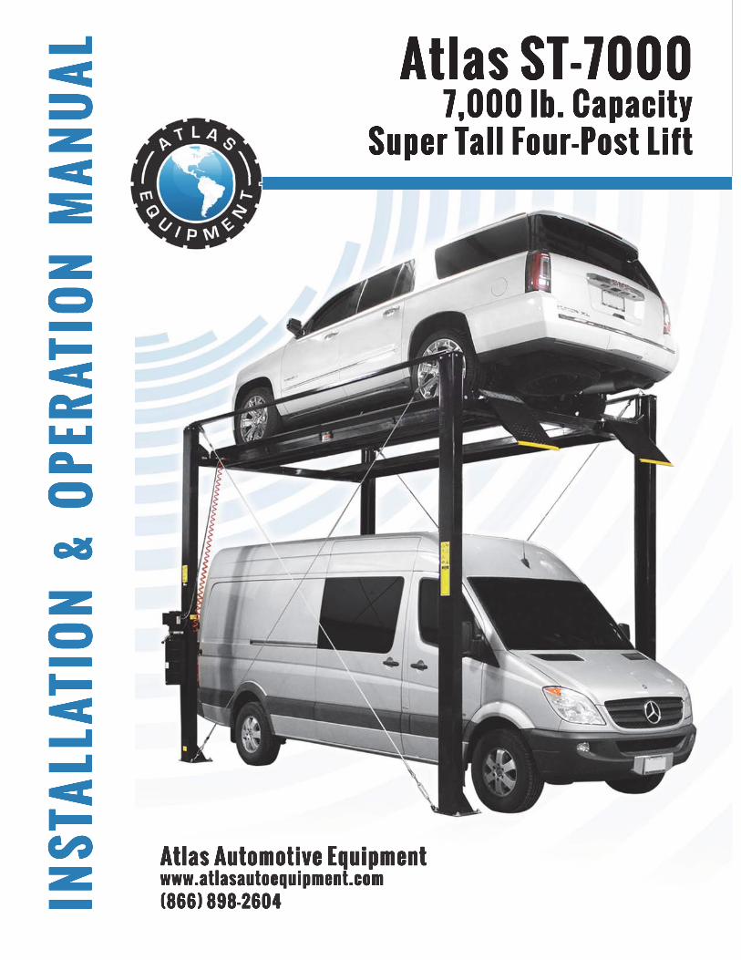
Replace This With Cover PDF
Read this entire manual before operation begins.
Record below the following information which is located on the serial number data plate.
Serial No. Model No. Date of Installation

ContentsImportant Information . . . . . . . . 4
Specifi cations . . . . . . . . . . . . . 5
Installation Requirements . . . . . . . 6
Installation Procedure . . . . . . . . . 9
Lift Lockout/Tagout Procedure . . . . . 22
Important Safety Instructions . . . . . 24
Operation Instructions. . . . . . . . . 26
Troubleshooting. . . . . . . . . . . . 30
Cable Inspection Guide . . . . . . . . 33
Illustrated Parts Breakdown . . . . . . 38
Parts List . . . . . . . . . . . . . . . 43
Warranty . . . . . . . . . . . . . . . 47

Important Information 4ST-7000
Important Information1. Always inspect the lift for damage and make note of any damage on the bill
of lading.
2. In case of freight damage, call the truck line immediately and report the damage as a freight claim.
3. Make sure you have extra help or heavy duty lifting equipment when unloading and assembling the lift.
4. Please read the safety procedures and operating instructions in this manual before operating lift. Keep this manual near lift at all times. Make sure all operators read this manual.
5. Never raise a car until you have double checked all bolts, nuts and hose fi ttings.
6. Always lower the lift to locks before going under the vehicle or storing another vehicle underneath lift. Never allow anyone to go under the lift when raising or lowering.
This is a vehicle lift installation/operation manual and no attempt is made or implied herein to instruct the user in lifting methods particular to an individual application. Rather, the contents of this manual are intended as a basis for operation and maintenance of the unit as it stands alone or as it is intended and anticipated to be used in conjunction with other equipment.
Proper application of the equipment described herein is limited to the parameters detailed in the specifi cations and the uses set forth in the descriptive passages. Any other proposed application of this equipment should be documented and submitted in writing to the factory for examination. The user assumes full responsibility for any equipment damage, personal injury, or alteration of the equipment described in this manual or any subsequent damages.
Read this manual thoroughly before installing, operating, or maintaining this lift. When done with installation, be sure to return documents to package and give all materials to lift owner/operator. When installation is complete be sure to run lift up and down a few cycles with and without “typical” vehicle loaded on lift.
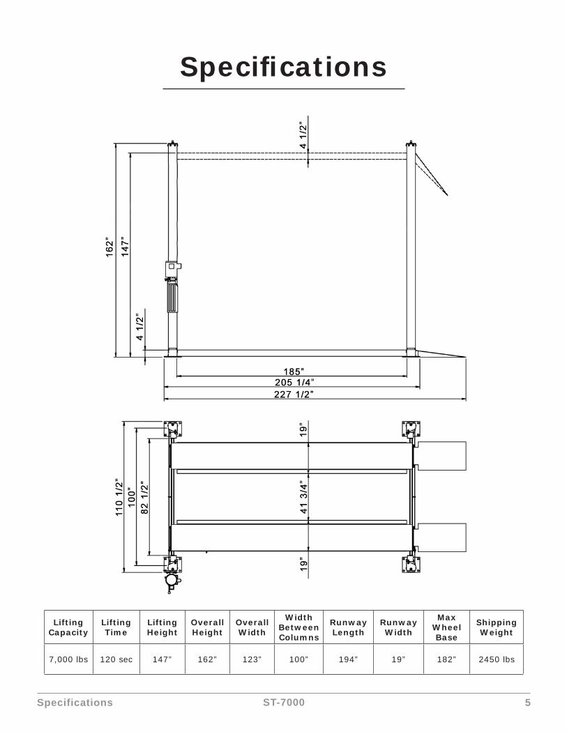
Specifications 5ST-7000
Specifi cations
Lifting Capacity
Lifting Time
Lifting Height
Overall Height
Overall Width
Width Between Columns
Runway Length
Runway Width
Max Wheel Base
Shipping Weight
7,000 lbs 120 sec 147” 162” 123” 100” 194” 19” 182” 2450 lbs
Installation Requirements 6ST-7000
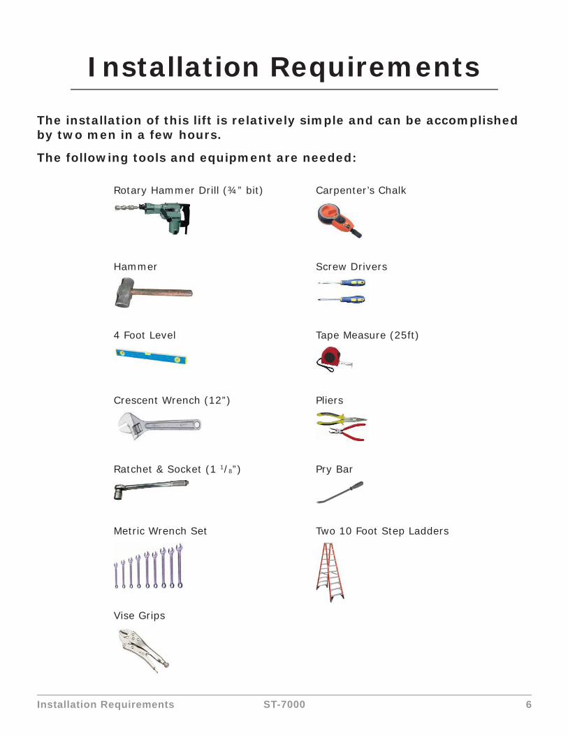
Installation Requirements
The installation of this lift is relatively simple and can be accomplished by two men in a few hours.
The following tools and equipment are needed:
Rotary Hammer Drill (¾” bit) Carpenter’s Chalk
Hammer Screw Drivers
4 Foot Level Tape Measure (25ft)
Crescent Wrench (12”) Pliers
Ratchet & Socket (1 1/8”) Pry Bar
Metric Wrench Set Two 10 Foot Step Ladders
Vise Grips
Installation Requirements 7ST-7000
Concrete Specifi cations
Concrete specifi cations must be followed accordingly.
Failure to do so may result in lift and/or vehicle falling.
CAUTION!! DO NOT use on asphalt or similar unstable surfaces.
1. Concrete must have 4 inches minimum and must be totally cured before lift installation.
2. Concrete must be in good condition and must have a test strength of 3,000psi minimum.
3. Floors must be level with no cracks or holes.
4. If the top of the anchor exceeds 2 ¼” above the fl oor grade,you DO NOT have enough embedment.
5. Maintain a 6” minimum distance from any slab edge or seam. Hole to hole spacing should be a minimum 6 ½” in any direction. Hole depth should be a minimum of 4”.
6. Shim each column base as required until each column is plumb. If one column has to be elevated to match the plane of the other column, full size base shim plates should be used. Shim thickness MUST NOT exceed ½” when using the 5 ½” long anchors with the lift. Adjust the column extensions plumb.
7. If anchors do not tighten to 110 ft-lbs. installation torque, replace the concrete under each column base with a 4’ x 4’ x 6” thick 3,000 PSI minimum concrete pad keyed under and fl ush with the top of existing fl oor. Allow concrete to cure before installing lifts and anchors (typically 2 to 3 weeks).
CAUTION!!
LUBRICATE ALL CABLE SHEAVES, BEARINGS, AND SHAFTS WITH GREASE PRIOR TO OPERATING THE
LIFT. LUBRICATE ALL ON AN ANNUAL BASIS.
Motors and all electrical components are not sealed against the weather and moisture. Install this lift in a protected indoor location. Failure by the owner to provide the recommended shelter could result in
unsatisfactory lift performance, property damage, or personal injury.

Installation Requirements 8ST-7000
Power Supply
220 volt single phase motor on a 30 amp breaker with minimum of 10 gauge wire. Operating voltage range is 208v-230v.
Air Supply
Air pressure requirement: 75-120 PSI.

Installation Procedure 9ST-7000
Installation Procedure
1. Open the outer packing carefully.
2. Remove plastic wrap from top runway and remove all hardware, safety lock rods, hoses and cables.

Installation Procedure 10ST-7000
3. Find the end of the hose that is already mounted to the cylinder and tighten the elbow that attaches the hose to the side of the runway using the jam nut. Also, check the fi tting at the cylinder end and make sure it is tight. Make sure air lines are connected to the air fi ttings under the runway.
Installation Procedure 11ST-7000
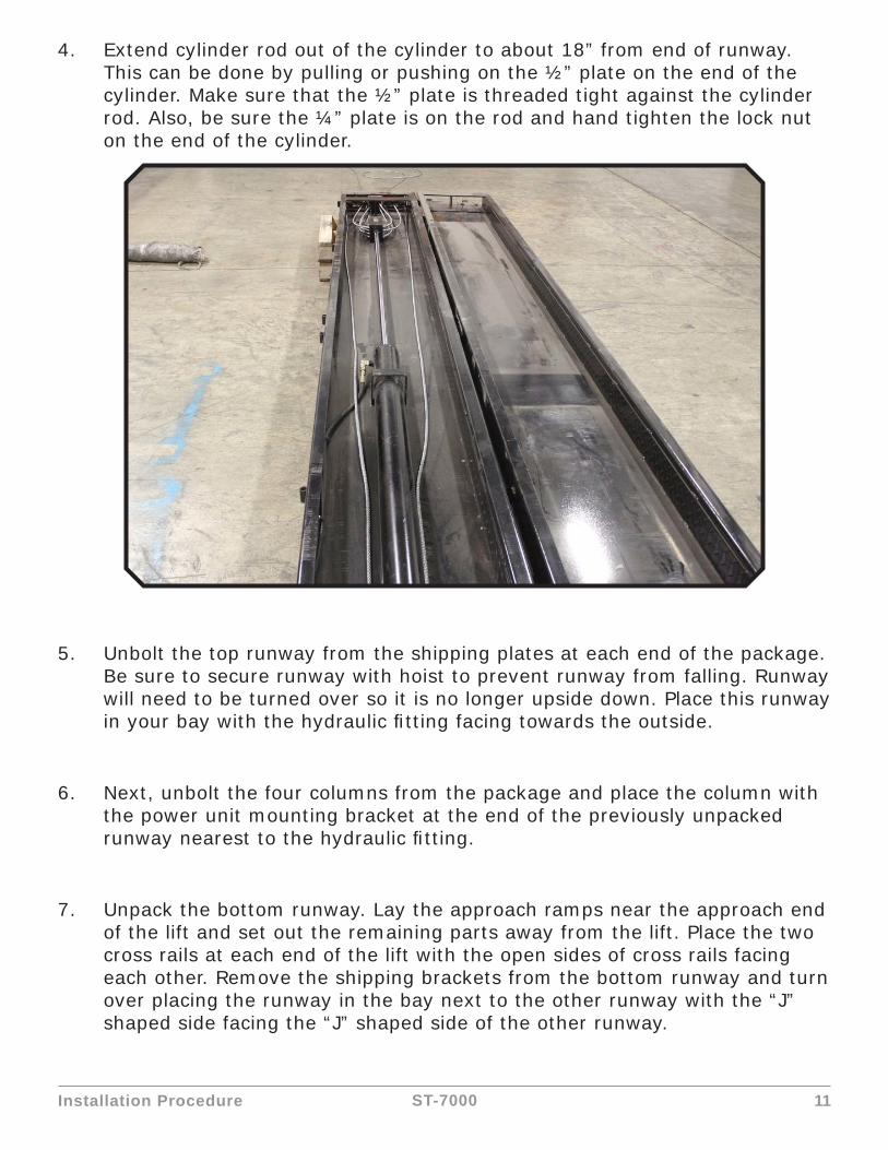
4. Extend cylinder rod out of the cylinder to about 18” from end of runway. This can be done by pulling or pushing on the ½” plate on the end of the cylinder. Make sure that the ½” plate is threaded tight against the cylinder rod. Also, be sure the ¼” plate is on the rod and hand tighten the lock nut on the end of the cylinder.
5. Unbolt the top runway from the shipping plates at each end of the package. Be sure to secure runway with hoist to prevent runway from falling. Runway will need to be turned over so it is no longer upside down. Place this runway in your bay with the hydraulic fi tting facing towards the outside.
6. Next, unbolt the four columns from the package and place the column with the power unit mounting bracket at the end of the previously unpacked runway nearest to the hydraulic fi tting.
7. Unpack the bottom runway. Lay the approach ramps near the approach end of the lift and set out the remaining parts away from the lift. Place the two cross rails at each end of the lift with the open sides of cross rails facing each other. Remove the shipping brackets from the bottom runway and turn over placing the runway in the bay next to the other runway with the “J” shaped side facing the “J” shaped side of the other runway.

Installation Procedure 12ST-7000
8. Lay the columns down and remove the top plates to allow the cross rails to be slid into the columns.
9. Slide each cross rail into the front or rear two columns. Repeat this step for the other cross rails.
10. Slide the locking ladders into the cross rail.

Installation Procedure 13ST-7000
11. Attach the top cap with the four bolts and tighten down the locking nuts on the lock ladders.
12. Stand the front columns up at 205 ¼” from the rear cross rail columns by measuring from the outsides of the columns. Square the lift by measuring diagonally between the left, front column to the same position on the right, rear column. Compare your measurement between the left, front column and the right, rear column. This should be within ½” to allow some forgiveness to bolt on runways.
13. Raise front and rear cross rails up to fi rst locking position.

Installation Procedure 14ST-7000
14. Lift the powerside runway up close to the cross rails. Then, route the cables through the cross rails and attach the air lines.
15. Position the runways and bolt them to the cross rails.
Installation Procedure 15ST-7000
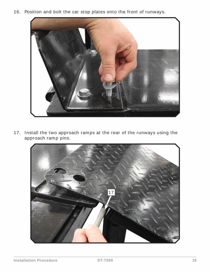
16. Position and bolt the car stop plates onto the front of runways.
17. Install the two approach ramps at the rear of the runways using the approach ramp pins.
17
Installation Procedure 16ST-7000
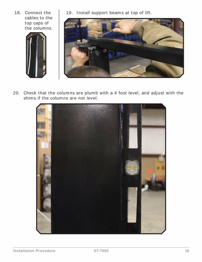
18. Connect the cables to the top caps of the columns.
19. Install support beams at top of lift.
20. Check that the columns are plumb with a 4 foot level, and adjust with the shims if the columns are not level.

Installation Procedure 17ST-7000
21. Prepare the Anchor Bolts.
22. Using a rotary hammer drill, drill all the anchor holes and install the anchor bolts. Do not tighten the bolts yet.
23. Install the support cable anchoring point bracket.
24. Tighten the anchor bolts. If the top of the anchor bolt exceeds 2 ¼” above the floor grade, you DO NOT have enough concrete (or a deep enough hole). Tighten the anchor bolts to 110 ft-lbs.
Lock washer
Washer
Nut
Drilling Cleaning Bolting
Installation Procedure 18ST-7000
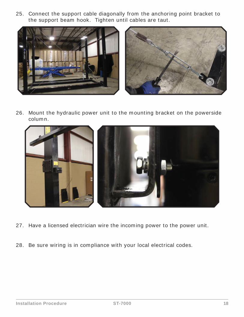
25. Connect the support cable diagonally from the anchoring point bracket to the support beam hook. Tighten until cables are taut.
26. Mount the hydraulic power unit to the mounting bracket on the powerside column.
27. Have a licensed electrician wire the incoming power to the power unit.
28. Be sure wiring is in compliance with your local electrical codes.

Installation Procedure 19ST-7000
29. Connect hydraulic lines from the runway to the power unit.
30. Install lock release valve.

Installation Procedure 20ST-7000
31. Connect the coiled air line from the runway to the lock release valve.
32. Install air regulator and connect the black 8mm air line from the air regulator to the lock release valve.
33. Pour 7 gallons of AW-32 hydraulic fl uid into the power unit reservoir.(Available at any auto supply store)
Installation Procedure 21ST-7000
34. Connect air supply to regulator. (Air pressure requirement: 75-120 PSI)
35. Check over cables and make sure they are all in their pulleys. Press the up switch on the power unit and the fl uid will start to pump into the cylinder. The lift will eventually raise after the cylinder fi lls up.
36. To lower the lift, press and hold the lock release valve while pressing and holding the lowering handle on the power unit. Keep holding the lowering handle on the power unit after the lift reaches the fl oor. You will hear all the air escape.
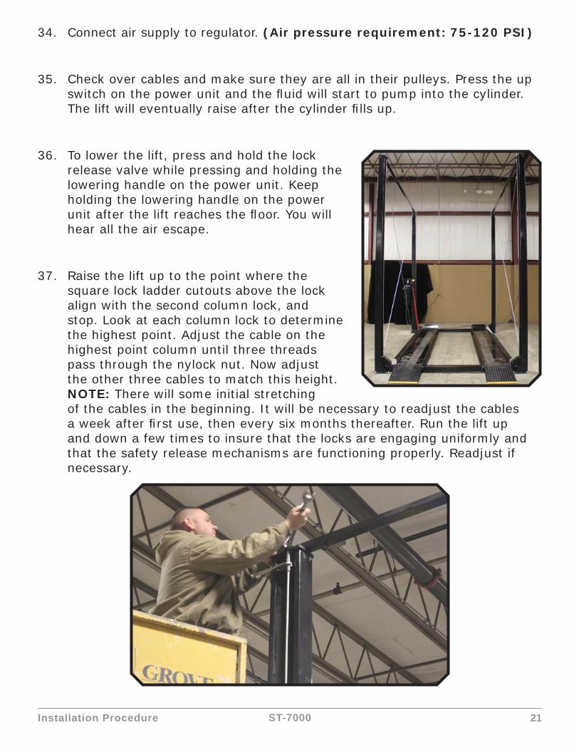
37. Raise the lift up to the point where the square lock ladder cutouts above the lock align with the second column lock, and stop. Look at each column lock to determine the highest point. Adjust the cable on the highest point column until three threads pass through the nylock nut. Now adjust the other three cables to match this height.NOTE: There will some initial stretching of the cables in the beginning. It will be necessary to readjust the cables a week after fi rst use, then every six months thereafter. Run the lift up and down a few times to insure that the locks are engaging uniformly and that the safety release mechanisms are functioning properly. Readjust if necessary.
Lift Lockout/Tagout Procedure 22ST-7000
Lift Lockout/Tagout Procedure
Purpose
This procedure establishes the minimum requirements for the lockout of energy that could cause injury to personnel by the operation of lifts in need of repair or being serviced. All employees shall comply with this procedure.
Responsibility
The responsibility for assuring that this procedure is followed is binding upon all employees and service personnel from outside service companies (i.e., Authorized Installers, contractors, etc.). All employees shall be instructed in the safety signifi cance of the lockout procedure by the facility owner/manager. Each new or transferred employee along with visiting outside service personnel shall be instructed by the owner/manager (or assigned designee) in the purpose and use of the lockout procedure.
Preparation
Employees authorized to perform lockout shall ensure that the appropriate energy isolating device (i.e., circuit breaker, fuse, disconnect, etc.) is identifi ed for the lift being locked out. Other such devices for other equipment may be located in close proximity of the appropriate energy isolating device. If the identity of the device is in question, see the shop supervisor for resolution. Assure that proper authorization is received prior to performing the lockout procedure.
Sequence of Lockout Procedure
1. Notify all affected employees that a lockout is being performed and the reason for it.
2. Unload the subject lift. Shut it down and assure the disconnect switch is “OFF” if one is provided on the lift.
Lift Lockout/Tagout Procedure 23ST-7000
3. The authorized lockout person operates the main energy isolation device removing power to the subject lift.
a. If this is a lockable device, the authorized lockout person places the assigned padlock on the device to prevent its unintentional reactivation. An appropriate tag is applied stating the person’s name, at least 3” x 6” in size, an easily noticeably color, and states not to operate device or remove tag.
b. If this device is a non-lockable circuit breaker or fuse, replace with a “dummy” device and tag it appropriately as mentioned above.
4. Attempt to operate lift to assure the lockout is working. Be sure to return any switches to the “OFF” position.
5. The equipment is now locked out and ready for the required maintenance or service.
Restoring Equipment to Service
1. Assure the work on the lift is complete and the area is clear of tools, vehicles, and personnel.
2. At this point, the authorized person can remove the lock (or dummy circuit breaker or fuse) and tag and activate the energy isolating device so that the lift may again be placed into operation.
Rules for Using Lockout Procedure
Use the Lockout Procedure whenever the lift is being repaired or serviced, waiting for repair when current operation could cause possible injury to personnel, or for any other situation when unintentional operation could injure personnel. No attempt shall be made to operate the lift when the energy isolating device is locked out.
Operating Conditions
Lift is not intended for outdoor use and has an operating ambient temperature range of 41º-104ºF (5º-40ºC).

Important Safety Instructions 24ST-7000
Important Safety Instructions
When using your garage equipment, basic safety precautions should always be followed, including the following:
1. Read all instructions
2. Care must be taken as burns can occur from touching hot parts.
3. Do not operate equipment with a damaged cord or if the equipment has been dropped or damaged - until it has been examined by a qualifi ed service person.
4. Do not let a cord hang over the edge of the table, bench, or counter or come in contact with hot manifolds or moving fan blades.
5. If an extension cord is necessary, a cord with a current rating equal to or more than that of the equipment should be used. Cords rated for less current than the equipment may overheat.
6. Always unplug equipment from electrical outlet when not in use. Never use the cord to pull the plug from the outlet. Grasp plug and pull to disconnect.
7. Let equipment cool completely before putting away. Loop cord loosely around equipment when storing.
8. To reduce the risk of fi re, do not operate equipment in the vicinity of open containers of fl ammable liquids (gasoline).
9. Adequate ventilation should be provided when working on operating internal combustion engines.
10. Keep hair, loose clothing, fi ngers, and all parts of body away from moving parts.
11. To reduce the risk of electric shock, do not use on wet surfaces or expose to rain.
12. Use only as described in this manual. Use only manufacturer’s recommended attachments.
13. ALWAYS WEAR SAFETY GLASSES. Everyday eyeglasses only have impact resistant lenses, they are not safety glasses.

Important Safety Instructions 25ST-7000
Save These Instructions
Safety Procedures
• Never allow unauthorized persons to operate lift. Thoroughly train new employees in the use and care of lift.
• Caution - the power unit operates at high pressure.• Remove passengers before raising vehicle.• Prohibit unauthorized persons from being in shop area while lift is in use.• Total lift capacity is 7,000 lbs. Do not exceed this capacity.• Prior to lifting vehicle, walk around the lift and check for any objects that
might interfere with the operation of lift and safety latches; tools, air hoses, shop equipment.
• When approaching the lift with a vehicle, make sure to center the vehicle between the columns. Slowly drive the vehicle up with someone outside the vehicle guiding the driver.
• Prior to lowering vehicle, walk around the lift and check for any objects that might interfere with the operation of lift and safety latches; tools, air hoses, shop equipment.
• Slowly drive the vehicle on and off of the lift. Have someone outside the vehicle guide the driver.
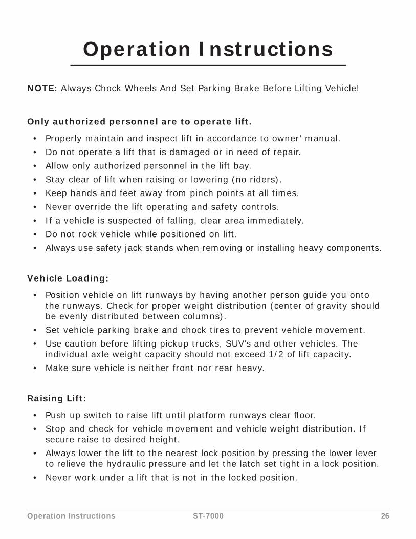
Operation Instructions 26ST-7000
Operation Instructions
NOTE: Always Chock Wheels And Set Parking Brake Before Lifting Vehicle!
Only authorized personnel are to operate lift.
• Properly maintain and inspect lift in accordance to owner’ manual.• Do not operate a lift that is damaged or in need of repair.• Allow only authorized personnel in the lift bay.• Stay clear of lift when raising or lowering (no riders).• Keep hands and feet away from pinch points at all times.• Never override the lift operating and safety controls.• If a vehicle is suspected of falling, clear area immediately.• Do not rock vehicle while positioned on lift.• Always use safety jack stands when removing or installing heavy components.
Vehicle Loading:
• Position vehicle on lift runways by having another person guide you onto the runways. Check for proper weight distribution (center of gravity should be evenly distributed between columns).
• Set vehicle parking brake and chock tires to prevent vehicle movement.• Use caution before lifting pickup trucks, SUV’s and other vehicles. The
individual axle weight capacity should not exceed 1/2 of lift capacity.• Make sure vehicle is neither front nor rear heavy.
Raising Lift:
• Push up switch to raise lift until platform runways clear fl oor.• Stop and check for vehicle movement and vehicle weight distribution. If
secure raise to desired height.• Always lower the lift to the nearest lock position by pressing the lower lever
to relieve the hydraulic pressure and let the latch set tight in a lock position.• Never work under a lift that is not in the locked position.

Operation Instructions 27ST-7000
Lowering Lift:
• Clear all obstacles from under lift and vehicle, and ensure only lift operator is in the lift area.
• Stay clear of lift and raise the lift off the safety locks.• Press the lock release valve and the lowering lever to begin descent.• Ensure lift is fully lowered, and having another person guide you, carefully
unload the lift by driving off of the lift runways.
CAUTION
PAY ATTENTION TO THE LOWERING SPEED OF ALL FOUR CORNERS. MAKE SURE THEY ARE MOVING DOWN AT THE SAME SPEED. STOP LOWERING THE LIFT BY RELEASING THE LOWERING LEVER ON THE POWER UNIT AND MOVING THE LOCK LEVER TO THE LOCK POSITION IF ANY CORNER STOPS MOVING OR IS SLOWER IN DESCENT. ALWAYS LOCK THE LIFT BEFORE GOING UNDER THE VEHICLE.
Preventive Maintenance Schedule
The periodic Preventive Maintenance Schedule given is the suggested minimum requirements and minimum intervals; accumulated hours or monthly period, which ever comes sooner.
Periodic maintenance is to be performed on a daily, weekly, and yearly basis as given in the following paragraphs.
WARNING!!
Occupational Safety and Health Administration (OSHA) and the American National Standards Institute (ANSI) requires users to inspect lifting equipment at the start of every shift. These and other periodic inspections are the responsibility of the user.
Failure to perform the daily pre-operational check can result in expensive property damage, lost production time, serious personal injury, and even death. The safety lock system must be checked and working properly before the lift is put to use.
Failure to heed this warning can result in death or serious injury, or damage to equipment. If you hear a noise not associated with normal lift operation, or, if there is any indications of impending lift failure - CEASE OPERATION IMMEDIATELY! - Inspect, correct and/or replace parts as required.

Operation Instructions 28ST-7000
Daily Pre-Operation Check (8-Hours)
• Check safety lock audibly and visually while in operation• Check hydraulic connections, and hoses for leakage.• Check cables connections bends, cracks-and for loose fi ttings.• Check for frayed cables in both raised and lowered position.• Check bolts, nuts, and screws and tighten if needed.• Check wiring & switches for damage.• Check fl oor for stress cracks near columns.• Check lubrications on cable sheaves and shafts.
Weekly Maintenance (every 40-Hours)
• Check anchor bolts torque to 110 ft-lbs for the ¾ in. anchor bolts. Do not use an impact wrench to tighten anchor bolts.
• Check fl oor for stress cracks near columns• Check hydraulic oil level.• Check and tighten bolts, nuts, and screws.• Check all cable sheaves/assembly for free movement or excessive wear on
cable sheave shaft.
Yearly Maintenance
• Lubricate the cable sheave shaft by using grease gun at least once a year after the lift is in service.
• Check for excessive wear of cable. Replace them if necessary.• Change the hydraulic fl uid - good maintenance procedure makes it
mandatory to keep hydraulic fl uid clean. No hard fast rules can be established; - operating temperature, type of service, contamination levels, fi ltration, and chemical composition of fl uid should be considered. If operating in dusty environment shorter interval may be required.
Special Maintenance Tasks
NOTE: The following items should only be performed by a trained maintenance expert:
• Replacement of hydraulic hoses.• Replacement of cables and sheaves.• Replacement or rebuilding air and hydraulic cylinders as required.• Replacement or rebuilding pumps / motors as required.• Checking of hydraulic cylinder rod and rod end (threads) for deformation or
damage.
Operation Instructions 29ST-7000
CAUTION
Relocating or changing components may cause problems. Each component in the system must be compatible; an undersized or restricted line will cause a drop in pressure. All valve, pump, and hose connections should be sealed and/or capped until just prior to use. Air hoses can be used to clean fi ttings and other components. However, the air supply must be fi ltered and dry to prevent contamination. Most important is cleanliness; Contamination is the most frequent cause of malfunction or failure of hydraulic equipment.

Troubleshooting 30ST-7000
Troubleshooting
The common problems that may be encountered and their probable causes are covered in the following paragraphs:
PROBLEM SOLUTION
Motor Does Not Operate
Failure of the motor to operate is normally caused by one of the following:
1. Breaker or fuse blown.
2. Faulty wiring connections; call electrician.
3. Defective up button; call electrician for service.
Motor Functions but Lift Will Not Rise
If the motor is functioning, but the lift will not rise do the following in the order given:
1. A piece of trash is under check valve. Push handle down and push the up button at the same time. Hold for 10-15 seconds. This should fl ush the system.
2. Check the clearance between the plunger valve of the lowering handle. There should be 1/16” clearance.
3. Remove the check valve cover and clean ball and seat.
WARNING!!Failure to properly relieve pressure in the following step can cause injury to personnel. This lift uses ISO Grade 32 or other good grade non-detergent hydraulic oil at a high hydraulic pressure. Be familiar with its toxicological properties, precautionary measures to take, and fi rst aid measures as stated in the Safety Summary before performing any maintenance with the hydraulic system.
4. Oil level too low. Oil level should be just under the vent cap port when the lift is down. Relieve all hydraulic pressure and add oil as required.
Troubleshooting 31ST-7000
Oil Blows out Breather of Power Unit
If oil blows out of the breather of the power unit, take the following actions:
1. Oil reservoir overfi lled. Relieve all pressure and siphon out hydraulic fl uid until at a proper level
2. Lift lowered too quickly while under a heavy load. Lower the lift slowly under heavy loads.
Motor Hums and Will Not Run
If the motor hums but fails to run, take the following actions:
1. Lift overloaded. Remove excessive weight from lift
WARNING!!The voltages used in the lift can cause death or injury to personnel. In the following steps, make sure that a qualifi ed electrician is used to perform maintenance
2. Faulty wiring Call electrician
3. Bad capacitor Call electrician
4. Low voltage Call electrician
Lift Jerks Going Up and Down
1. If the lift jerks while going up and down, it is usually a sign of air in the hydraulic system. Raise lift all the way to top and return to fl oor. Repeat 4-6 times. Do not let this overheat power unit.
Oil Leaks Oil leak causes at the power unit and cylinders are normally caused by the following:
1. Power unit: if the power unit leaks hydraulic oil around the tank-mounting fl ange check the oil level in the tank. The level should be two inches below the fl ange of the tank. A screwdriver can be used as a “dipstick”.
2. Cylinder - Piston Rod: the rod seal of the cylinder is out. Rebuild or replace the cylinder.
3. Cylinder - Vent: the piston seal of the cylinder is out. Rebuild or replace the cylinder.
Troubleshooting 32ST-7000
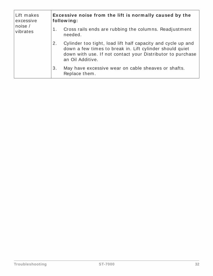
Lift makes excessive noise / vibrates
Excessive noise from the lift is normally caused by the following:
1. Cross rails ends are rubbing the columns. Readjustment needed.
2. Cylinder too tight, load lift half capacity and cycle up and down a few times to break in. Lift cylinder should quiet down with use. If not contact your Distributor to purchase an Oil Additive.
3. May have excessive wear on cable sheaves or shafts. Replace them.

Cable Inspection Guide 33ST-7000
Cable Inspection Guide
Maximum Allowable Cable Necking
Nom. Cable Diameters Max. Reduction in DiameterUp to 5/16” 1/64”3/8” to 1/2” 1/32”9/16” to 3/4” 3/64”7/8” to 1-1/8” 1/16”
1-1/4” to 1-1/2” 3/32”
Typical Good Cable Cable With Broken Wires
Cable With Severe Corrosion Cable With Necking

Cable Inspection Guide 34ST-7000
Daily Inspection & Maintenance
1. Cleanliness: Cables, Columns, Runways and other lift parts should be kept free of corrosive agents, solvents, and road salts. If such agents are spilled or splashed on any lift component, immediately rinse thoroughly with water and wipe down with a clean rag. Spray wire rope cables as required with Penetrating Oil and wipe down. Failure to keep lift free of corrosive agents and solvents will lead to reduced component service life, cable failure, etc., which could result in property damage and/or personal injury.
2. Fasteners: Check all the attaching bolts and nuts for tightness.
3. Cables: Check wire rope cables for wear or damage. Any cable with broken wires, severe corrosion, excessive stretch, deformed strands, variations in diameter (necking), or any change from its normal appearance, must be replaced. If any cable is found to be in need of replacement, the entire cable set must be replaced immediately. Refer to fi gures below.
4. Sheaves: Check sheaves (pulleys) for wear or damage, i.e. wobble (tilt), cracks, loose on pin, or excessive noise during operation.
5. Sheave Pins: Check for loose or missing sheave (pulley) pins.
6. Locking Latches and Slack Cable Devices: Watch locking latches and slack cable devices during lift operation to ensure that latches work properly and line up with slots in latch plate located in columns.
Monthly Inspection & Maintenance
1. Cables
a. Clean wire rope cables with lift in both lowered and raised position by spraying with Penetrating Oil and wiping the cable down.
b. Adjust cables using procedures on following pages.
2. Slack Cable Device: Inspect slack cable devices.
3. Column Anchor Bolts: Check column anchor bolts for tightness. Re-torque anchors bolts to 110 ft-lbs. If anchors do not tighten to the required installation torque, replace concrete under each column base per installation instructions. Let concrete cure before installing lifts and anchors.
4. Columns: Look for corrosion, giving special attention to the area at the base of the column. Check severely corroded areas by pecking with an awl or welder’s chipping hammer. If column is corroded through at any point it must be replaced immediately. If not corroded through, remove old paint and rust scale, then coat with a high quality corrosion resistant paint.
Cable Inspection Guide 35ST-7000
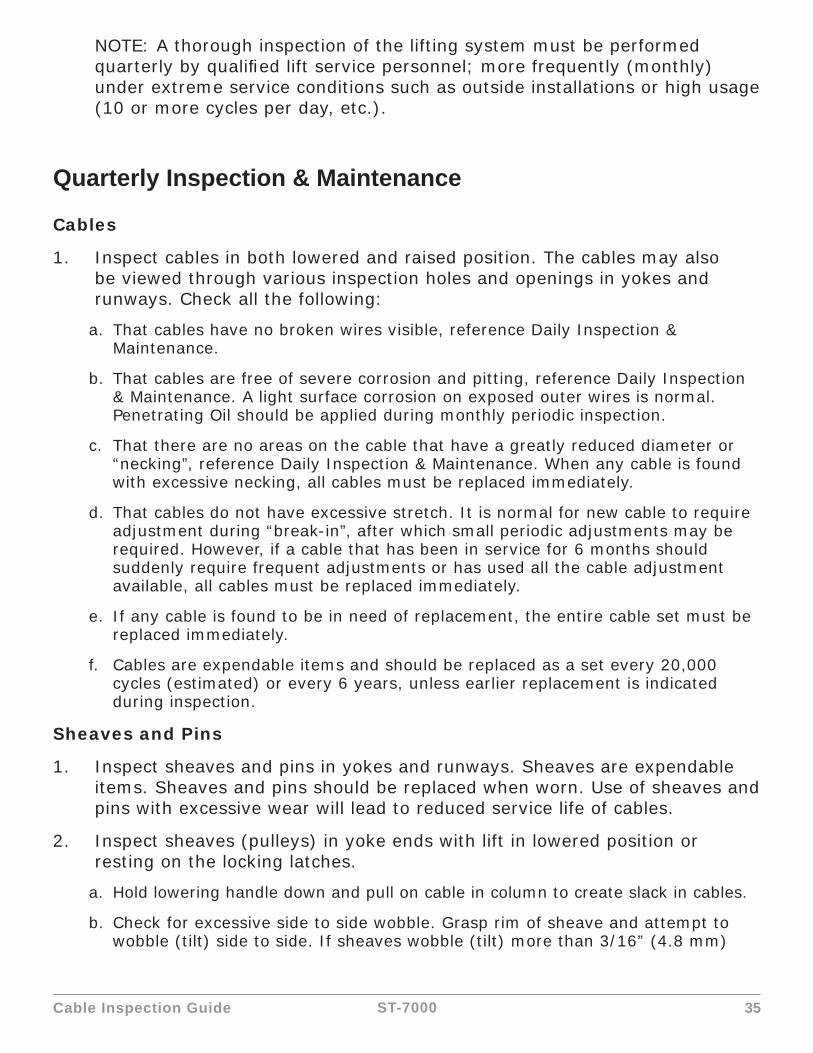
NOTE: A thorough inspection of the lifting system must be performed quarterly by qualifi ed lift service personnel; more frequently (monthly) under extreme service conditions such as outside installations or high usage (10 or more cycles per day, etc.).
Quarterly Inspection & Maintenance
Cables
1. Inspect cables in both lowered and raised position. The cables may also be viewed through various inspection holes and openings in yokes and runways. Check all the following:
a. That cables have no broken wires visible, reference Daily Inspection & Maintenance.
b. That cables are free of severe corrosion and pitting, reference Daily Inspection & Maintenance. A light surface corrosion on exposed outer wires is normal. Penetrating Oil should be applied during monthly periodic inspection.
c. That there are no areas on the cable that have a greatly reduced diameter or “necking”, reference Daily Inspection & Maintenance. When any cable is found with excessive necking, all cables must be replaced immediately.
d. That cables do not have excessive stretch. It is normal for new cable to require adjustment during “break-in”, after which small periodic adjustments may be required. However, if a cable that has been in service for 6 months should suddenly require frequent adjustments or has used all the cable adjustment available, all cables must be replaced immediately.
e. If any cable is found to be in need of replacement, the entire cable set must be replaced immediately.
f. Cables are expendable items and should be replaced as a set every 20,000 cycles (estimated) or every 6 years, unless earlier replacement is indicated during inspection.
Sheaves and Pins
1. Inspect sheaves and pins in yokes and runways. Sheaves are expendable items. Sheaves and pins should be replaced when worn. Use of sheaves and pins with excessive wear will lead to reduced service life of cables.
2. Inspect sheaves (pulleys) in yoke ends with lift in lowered position or resting on the locking latches.
a. Hold lowering handle down and pull on cable in column to create slack in cables.
b. Check for excessive side to side wobble. Grasp rim of sheave and attempt to wobble (tilt) side to side. If sheaves wobble (tilt) more than 3/16” (4.8 mm)

Cable Inspection Guide 36ST-7000
side to side or move up and down on shaft more than 1/32” (0.8 mm), the sheave and pin (shaft) should be replaced, refer fi gures below.
c. Check sheaves and replace if cracks are found.
d. Check for ease of rotation. If sheaves do not turn freely, the sheave and sheave pin should be removed, inspected, lubricated, and reinstalled or replaced.
3. Fully raise lift. Inspect sheaves (pulleys) in runway ends with lift in raised position.
a. Visually inspect alignment of sheaves, see fi gure above. Misalignment of sheave(s) indicates excessive wear; the sheave(s) and sheave pin should be removed and inspected. Replace as required.
b. Hold lowering handle down to lower lift onto latches. Pull on cables under runway to create cable slack.
c. Check for excessive side to side wobble. Grasp rim of sheave and attempt to wobble (tilt) side to side, refer to fi gures above. If sheaves wobble (tilt) more than 1/16” (1.6 mm) side to side, or move in and out more than 1/32” (0.8 mm), the sheave and sheave pin (shaft) should be replaced, refer to fi gures above.
Hydraulic Cylinder
1. Inspect the hydraulic cylinder mounting to the runway. Inspect cylinder and hydraulic hoses for leaks. Repair or replace as required.
a. Check and tighten the hydraulic cylinder rod nuts holding the cable pull bar.
TRACKS for Rolling Jack and Oil Drain Pan
1. Inspect rolling jack/oil drain pan tracks for cleanliness, corrosion, excessive wear or damage.
2. Clean dirty tracks.
3. Worn or damaged tracks must be repaired immediately. Failure to do so will lead to reduced service life which could result in property damage and/or personal injury.
Latch Inspection and Adjustment
1. Check locking latches for proper operation. Inspect for worn or missing parts. Replace worn or damaged parts and adjust as required.
2. Latches - Check latch operation on all four corners.
3. Latch and Latch Bar Line-Up - Observe locking latches during lift operation to ensure that all latches line up with slots in latch bar located in all four columns. If not, relocate and/or re-shim columns.
a. Check slack cable devices for proper operation. Inspect for worn or missing parts. Replace worn or damaged parts as required.
Cable Inspection Guide 37ST-7000
b. Observe both locking latches and slack cable devices during lift operation to ensure that all latches line up with slots in latch bar located in all four columns.
Cable Adjustment
1. Initial Adjustment
a. Adjust cable with lift fully lowered. Loosen jam nut and tighten nut on cable stud on top of column until yoke end is raised 1/4” (6.4 mm) and back off nut one turn. Re-tighten jam nut. Repeat for all four cables.
2. Final Adjustment
a. Load a typical vehicle on lift.
b. Raise lift as high as it will travel (full height). You should hear the locking latches click through all latch slots simultaneously.
c. Lower lift onto top latch position.
d. Check clearance:
i. Starting with the right front column, use a straight edge to mark the position of the yoke bottom on the column.
ii. Raise lift to full height again. Mark second position. If gap between two marks is less than 2”, adjust locking latch bar to reach clearance of 2”. Repeat for the other three columns.
iii. Adjust locking latch bar adjusting nut so that the bottom of the topmost latch bar slot is at least 2” below locking latch. After adjustment, tighten jam nut underneath column top plate, Fig. 11.
iv. If entire 2” clearance cannot be attained by adjusting the locking latch bar, adjust the cable. Turn cable adjusting nut to raise the locking latch 2” above bottom of latch bar slot. Tighten cable jam nut.
v. Lower lift and remove vehicle.
vi. Raise the lift to full height. LISTEN and WATCH as the fi rst locking latch clicks into place. Synchronize the other three columns with this column by adjusting their cables so all four latches click at same time. Tighten jam nuts. When making changes to adjustment nuts on cable end or latch bar stud, always leave at least two threads showing between nut and stud end. Latches may not click in at the same time when vehicle is being raised. They should be close. Be sure all four corners have passed the locking latch bar slot before lowering lift on locking latches

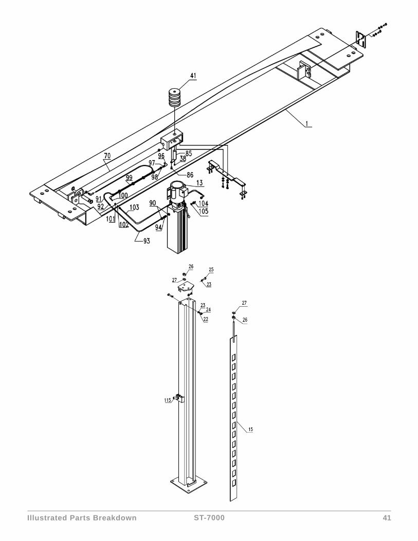
Illustrated Parts Breakdown 38ST-7000
Illustrated Parts Breakdown
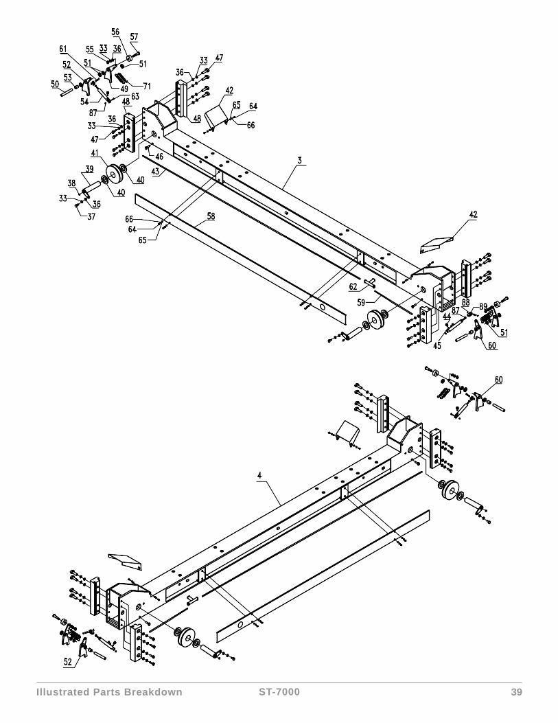
Illustrated Parts Breakdown 39ST-7000

Illustrated Parts Breakdown 40ST-7000
Illustrated Parts Breakdown 41ST-7000

Illustrated Parts Breakdown 42ST-7000
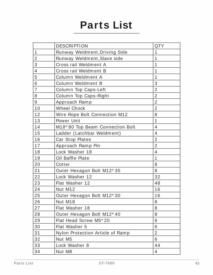
Parts List 43ST-7000
Parts List
DESCRIPTION QTY1 Runway Weldment,Driving Side 12 Runway Weldment,Slave side 13 Cross rail Weldment A 14 Cross rail Weldment B 15 Column Weldment A 16 Column Weldment B 37 Column Top Caps-Left 28 Column Top Caps-Right 29 Approach Ramp 210 Wheel Chock 212 Wire Rope Bolt Connection M12 813 Power Unit 114 M18*80 Top Beam Connection Bolt 415 Ladder (Latchbar Weldment) 416 Car Stop Plates 217 Approach Ramp Pin 218 Lock Washer 18 419 Oil Baffl e Plate 120 Cotter 821 Outer Hexagon Bolt M12*35 822 Lock Washer 12 3223 Flat Washer 12 4824 Nut M12 1625 Outer Hexagon Bolt M12*30 1626 Nut M18 827 Flat Washer 18 828 Outer Hexagon Bolt M12*40 829 Flat Head Screw M5*20 630 Flat Washer 5 631 Nylon Protection Article of Ramp 232 Nut M5 633 Lock Washer 8 4434 Nut M8 4

Parts List 44ST-7000
35 Outer Hexagon Bolt M8*20 436 Flat Washer 8 4837 Outer Hexagon Bolt M8*15 838 Grease Fitting 839 Cable Pulley Pin of Cross Rail 440 Flat Washer 36 2441 Pulley 1042 Pulley Cover 243 Hose 8mm 244 Quick Coupling for Cylinder 445 Seal Gasket for Cylinder 446 Outer Hexagon Bolt M8*50 447 Outer Hexagon Bolt M8*35 3248 Slider 849 Safety Lock 450 Safety Lock Pin 451 Flat Washer 20 2852 Safety Lock-Right 253 Spring Spacer 454 Air Lock Cylinder 455 Lock Nut M8 456 Small Cable Pulley 457 Small Cable Pulley Pin 458 The Beam Plate 459 Hose 8mm 260 Safety Lock-Left 261 Air Cylinder Pin 462 T Fast Connection 363 Outer Hexagon Bolt M6*25 464 Flat Head Screw M6*15 1665 Flat Washer 6 1666 Lock Washer 6 1667 Nut M20 868 Outside Calipers 269 Hydraulic Cylinder Pin 170 Hydraulic Cylinder 171 Flat Washer 20 872 Wire Rope Lock Plate 173 The Slider Bracket for Cylinder 1

Parts List 45ST-7000
74 Small Slider for Cylinder 275 Flat Head Screw M6*15 476 Cable 12527mm 177 Cable 7615mm 178 Cable 6063mm 179 Cable 10975mm 180 Pulley Shaft Under Runway 281 Spacer 482 Spacer 283 Pulley Shaft Under Runway 284 Spacer 285 Cylinder Head Pulley Shaft 186 Flat Head Screw M8*15 187 Nut M6 888 Jump Ring for Air Cylinder 889 Y Fitting for Air Cylinder 490 Oil Return Quick Nut 291 Oil Return Pipe 8 192 Quick Head Directly 293 Oil Return Pipe 8 194 Oil Return Quick Fitting 195 Oil Baffl e Plate 196 Fitting ZG3/8 197 Gasket 16 198 Anti-Explosion Valve(9/16-2G3/8) 199 Hydraulic Hose 1100 Fitting 9/16 1101 Flat Washer 14 1102 Nut 9/16 1103 Hydraulic Hose 1104 Fitting 9/16 1105 Gasket 14 1106 Platform Protection Board 4107 Support Beam 2108 Fixed Rope 4109 Wire Rope Fixed Plate 4110 Anchor Bolt M19 16111 Flat Washer 19 16112 Lock Washer 20 16

Parts List 46ST-7000
113 Nut M19 16114 The Core Pin for Anchor Bolt 16115 Hand Control Valve 1116 Hose 8mm 1117 Hose 8mm 1118 Hose 8mm 1119 Hose 8mm 1120 Quick Fitting 2121 Silencer 2122 Oil-Water Separator 1123 Anchoring Point Bracket 4124 1/4 Oil Return Quick Fitting 1

Warranty 47ST-7000
WarrantyThis item is warranted for two (2) years on structural components and one (1) year on air or electric hydraulic power units, pneumatic power units, cylinders and major components from date of invoice. Wear items are covered by a 90 day warranty.
This LIMITED warranty policy does not include a labor warranty.
NOTE: ALL WARRANTY CLAIMS MUST BE PRE-APPROVED BY THE MANUFACTURER TO BE VALID.
The Manufacturer shall repair or replace at their option for this period those parts returned to the factory freight prepaid, which prove after inspection to be defective. This warranty will not apply unless the product is installed, used and maintained in accordance with the Manufacturers installation, operation and maintenance instructions.
This warranty applies to the ORIGINAL purchaser only, and is non-transferable. The warranty covers the products to be free of defects in material and workmanship but, does not cover normal maintenance or adjustments, damage or malfunction caused by: improper handling, installation, abuse, misuse, negligence, carelessness of operation or normal wear and tear. In addition, this warranty does not cover equipment when repairs or alterations have been made or attempted to the Manufacturer’s products.
THIS WARRANTY IS EXCLUSIVE AND IS LIEU OF ALL OTHER WARRANTIES EXPRESSED OR IMPLIED INCLUDING ANY IMPLIED WARRANTY OR MERCHANTABILITY OR ANY IMPLIED WARRANTY OF FITNESS FROM A PARTICULAR PURPOSE, AND ALL SUCH IMPLIED WARRANTIES ARE EXPRESSLY EXCLUDED.
THE REMEDIES DESCRIBED ARE EXCLUSIVE AND IN NO EVENT SHALL THE MANUFACTURER, NOR ANY SALES AGENT OR OTHER COMPANY AFFILIATED WITH IT OR THEM, BE LIABLE FOR SPECIAL CONSEQUENTIAL OR INCIDENTAL DAMAGES FOR THE BREACH OF OR DELAY IN PERFORMANCE OF THIS WARRANTY. THIS INCLUDES, BUT IS NOT LIMITED TO, LOSS OF PROFIT, RENTAL OR SUBSTITUTE EQUIPMENT OR OTHER COMMERCIAL LOSS.
PRICES: Prices and specifi cations are subject to change without notice. All orders will be invoiced at prices prevailing at time of shipment. Prices do not include any local, state or federal taxes.
RETURNS: Products may not be returned without prior written approval from the Manufacturer.
DUE TO THE COMPETITIVENESS OF THE SELLING PRICE OF THESE LIFTS, THIS WARRANTY POLICY WILL BE STRICTLY ADMINISTERED AND ADHERED TO.