repeating jansky’s experiment - sciencefghigo/janskyantenna/... · repeating jansky’s...
TRANSCRIPT

Repeating Jansky’s Experiment
NRAO - Green Bank, 1995-1996
With ringleaders :
Darrel Emerson, Sue Ann Heatherly, Frank Ghigo , Glen Langston,Ron Maddalena, Dana Balser
and special assistance byGrote Reber
Participation and help from
Naomi BatesHarley CarpenterCarl ChestnutRamon Creager
David GordonDon GordonRon GordonWes Grammer
Mike HolstineJay LockmanBob SimmonsTom Wilson
Jansky Memo Series No.10June 2008
Repeating Jansky’s Experiment
NRAO - Green Bank, 1995-1996
With ringleaders :
Darrel Emerson, Sue Ann Heatherly, Frank Ghigo , Glen Langston,Ron Maddalena, Dana Balser
and special assistance byGrote Reber
Participation and help from
Naomi BatesHarley CarpenterCarl ChestnutRamon Creager
David GordonDon GordonRon GordonWes Grammer
Mike HolstineJay LockmanBob SimmonsTom Wilson

Abstract of the presentation at the 188th Meeting of the American AstronomicalSociety. Madison, Wisconsin, June 1996.
A replica of Karl Jansky's "merry-go-round" antenna at the National Radio AstronomyObservatory* in Green Bank, West Virginia is being refurbished to make it a usable radiotelescope. Although receiver and data acquisition systems have been added which are moremodern than Jansky's, the antenna itself, including the feed and drive system, are very similar tothose used by Jansky.
The antenna is capable of mapping the whole accessible sky every day with a 25 degree beam at20 MHz. Since very little wide field mapping has been done at this frequency since Jansky's day,it is potentially interesting to look for possible changes that may have happened in the past 60+years to the flux densities of the brightest sources and the galactic emission.
These observations take advantage of the current solar minimum, during which 20 MHzobserving is often possible. When the refurbishment project is complete, the antenna may beused on a continuing basis for student projects in the teacher enhancement institutes that NRAOhosts. The progress to date on this project will be summarized, and preliminary observations willbe presented.
* The National Radio Astronomy Observatory is a facility of the National Science Foundation operated undercooperative agreement by Associated Universities, Inc.

Jansky at Bell Labs, ca. 1932

Our favorite pictures of Karl

Replicating Jansky's Antenna
It was Grote Reber's idea to build a copy of Jansky's antenna and locate itat the entrance to the National Radio Astronomy Observatory in GreenBank, West Virginia, as an historical monument.
His insistence that it be an accurate replica resulted in a usable antennawith similar properties to the original. The replica was completed inSeptember of 1964.

Reber’s Account:
Intermission. Many years later, when supervising thereconstruction of my dish (see Act 2) at Green Bank on theleft side of the front entrance, it occurred to me that itwould be appropriate to have a full-size reproduction ofJansky's merry-go-round on the right side.
I contacted George Southworth, who was a contemporaryof Jansky at Holmdel. He brought the idea to the attentionof people at Bell Laboratories. They concurred and startedthings in motion. Peculiarly enough, the same man was stillin charge of the carpenter shop that built the original nearlythirty years earlier, and all the drawings were still available.
By 1960, more experience had been gained and the headof the shop wanted to make the reconstruction differentand better than the original. After some persuasion, hefinally agreed to make it the same as the original.
From Grote Reber, J.Roy.Astron.Soc.Canada 1988, vol.82, 110.3, p.93,“A Play Called the Beginning of Radio Astronomy”

Reber's account, continued
The only piece of the original which could be found was the speed-reducing gearbox (now installed at Green Bank).
The original merry-go-round was mounted on front wheels and axles of FordModel-T cars. Such were plentiful in car junkyards during the 1930s. By 1960they were long gone.I decided to advertise in the Marlinton, West Virginia. newspaper because somemight still be lying around farm barnyards. Much to my surprise, an ample supplywas readily available. What to do about tires and tubes? Consultation with aSears catalogue produced the needed items.
Later I learned from A.C. Beck that the original used hard rubber tires fromModel-T trucks. Unfortunately, such went out of style many years ago.Accordingly, the reconstructed merry-go-round has pneumatic instead of solidtires, a relatively minor departure from authenticity.

Copies of the Drawings from Bell Labs, and Reber’s Correspondence, are stored inthe NRAO Archives in Charlottesville, VA
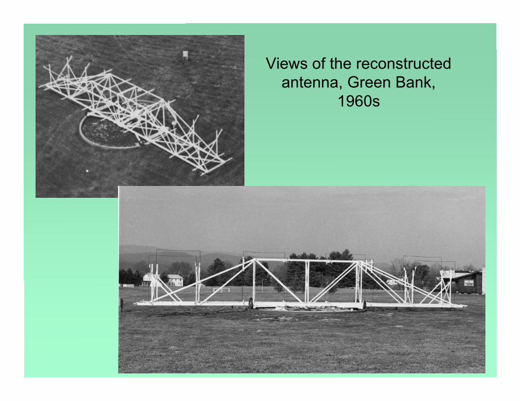
Views of the reconstructedantenna, Green Bank,
1960s

Renovation: 1995-1996
The replica of Jansky's antenna, after 30 years, wasdeteriorating. Some of the wooden structure wasrotting, and some of the brass conductors hadbroken. At the urging of one of us (D.Emerson), it wasdecided to put it back into working order.
Due to the solar minimum, now [1995-6] is the besttime for several years to come for a clear view of thesky at 20 MHz.
The renovation effort began in the summer of 1995.

Structure
The first job in the renovation was to repair the woodenstructure. Some of the wooden beams were replaced and thewhole structure was painted.
Broken brass pipes were replaced, and a half-wave copperpipe was added below the lower central part of the antenna tobe part of the matching network.
--thanks to Harley Carpenter and the Gordons of the NRAOcarpentry and mechanical shops.

Drive chainThe chain drive had not beenused for years, and the chaincould not be located. It wasfound that a Harley-Davidsonmotorcycle chain was the rightsize.
Three motorcycle chains joinedend-to end were used. Thesame motor and gear systemused by Jansky is still beingused. A gear tensioning idlerwas added.

Tires and Wheels
Surprisingly enough, itis still possible to ordertires for a model T !
A set of new tires wasbought to replaced theold ones.
Replacing some of thebroken wooden spokesin the wheels was doneby the observatorycarpenter, who madenew ones on a lathe.

Grote Reber VisitsGrote Reber visited Green Bank in the summers of 1995 and 1996. Some aspects of that visit were described by Sue Ann Heatherly in
"Travels With Grote", which was published in The Green Bank Tattler of September 1996,and also reprinted in "But It Was Fun: the first forty years of radio astronomy at Green Bank",
page 500, published by NRAO, 2007.
Grote's contributions to the Jansky antenna refurbishment are described in theseexcerpts from Heatherly's "Travels with Grote"
``In 1995 a bunch of us at NRAO decided it would be fun to re-doJansky's experiment. Since then, the ``Jansky Fellers,'' as we callourselves, have been using the antenna more-or-less as is. Theantenna was refurbished somewhat so that it could rotate under motorcontrol, but Fellers had to be present to bang the chain back on thegear every few minutes! Even worse, every two rotations, the antennahad to be stopped so that the Fellers could untangle coax cables whichgot wrapped around the center post. "

``The Fellers had hoped to interestGrote in making someobservations with the antenna thissummer. But he took one look atour set-up and said it was a mess!And it was. Under Grote'ssupervision, a coaxial slip joint wasinstalled which allows the antennato be rotated while connected to areceiver without tangled coax lines.This was no easy feat since itrequired drilling through about 18inches of concrete (special thanksto Harley Carpenter). "
Grote advises *
* From "Travels with Grote" by S.A.Heatherly

The Rotating Coaxial Joint

``Grote Reber instigated reconstruction of the gear box which was absolutely necessaryin order to keep the chain on the gears and not tear the motor up. The shop guys andmechanics did a beautiful piece of work there, by the way.
Grote accomplished in 3 weeks what the Jansky Fellers had not thought possible at all. Itmight have something to do with having the name Grote Reber, but I think his tactics hadsomething to do with it.
If Grote decided something had to be done, then we did it. Now! If he needed a partmachined he might just wait in the machine shop till it was ready. Or he would sit on theJansky Antenna and wait while I (or Carl Chestnut, or Dave Vandevender or H. A. Tayloror whoever) went to do his bidding.
You can't just sneak off to coffee while Grote Reber is sitting in the hot sun waiting foryour return."
Grote gets results
* From "Travels with Grote" by S.A.Heatherly

The Gearbox and chain drive
``For Grote, there was always an experiment waiting to be done, even in idlemoments.
While sitting out on the Jansky Antenna waiting for me to come back with awrench, or in his office waiting for a letter to be typed, Grote would conductexperiments with whatever was at hand.
Example: for several days while out at the Jansky Antenna, Grote counted thecars that went north and south on Route 92. He noticed that more cars wentnorth than south, and thought that was odd. By expanding his observations toother times during the day, Grote was able to report that it ``evened out"!
Another example: Grote made numerous tests on Sue Shears' [the electronicsdepartment secretary] calculator. He found out that an average timeof 28 seconds elapses between the last entry you make and the time itautomatically shuts off."
Always an experiment to be done *
* From "Travels with Grote" by S.A.Heatherly

The Matching Network
The counterpoise and matching network used by Jansky weremissing. We added a half-wave counterpoise 5 inches belowthe central element, as shown in Jansky's paper.
Jansky used a matching network of two tuned circuitsmagnetically coupled. Darrell Emerson measured about 30ohms at the feed point and recommended that we use themuch simpler approach of connecting a 50 ohm coax directlyto the driven element with the shield to the counterpoise,providing a good, although not perfect, match.

Jansky’s Matching Network

Our simplified matching network

AdditionsAmplifiers and a recording system ofsomewhat more recent vintage than theoriginal were added.
PreamplifierA preamplifier with switchable noisecalibration generator was built in-house andinstalled at the antenna to overcome losses inthe cable leading into the control room.
ReceiverA WWII surplus Signal Corps.Hallicraftersreceiver was used for the observationsrecorded here.
Recording systemA square-law detector and 8-bit digitizer werebuilt by summer students, A data acquisitionprogram runs on an IBM-type PC which cansample data at intervals from 55 ms to 60seconds, with option to do median filtering inorder to surpress interference spikes fromvehicles.

In the GB Lounge
New Receiver and DataRecording

Original Control Room,at Bell Labs, ca.1932

New control room
The closest building to theJansky antenna is theobservatory residence hall/cafeteria building. Thereceiver and data recordingsystem were placed in theupstairs lounge. The loungehas a fireplace, comfortablechairs, couches, and liquorcabinet, making it quite amore congenial controlroom than the ratherSpartan building Janskyused.

New Back end, and some of the Jansky "Fellers"
Left to right: Glen Langston, Frank Ghigo, Dana Balser, Sue Ann Heatherly, 1996
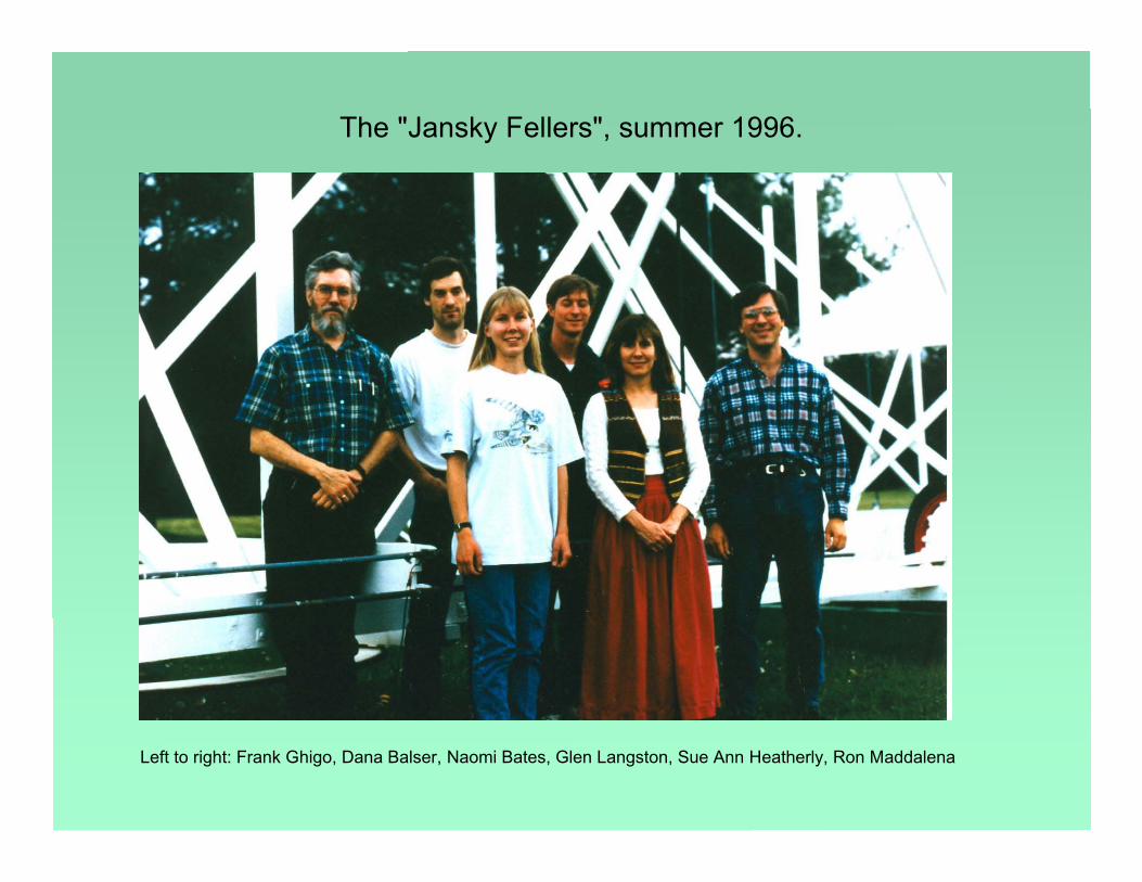
The "Jansky Fellers", summer 1996.
Left to right: Frank Ghigo, Dana Balser, Naomi Bates, Glen Langston, Sue Ann Heatherly, Ron Maddalena

End View

The Beam Pattern
Darrel Emerson calculated the beam profiles forthis antenna, which is a two-wavelength longBruce-type array. Each 12-foot segment is aquarter wavelength.
The rear element is a reflector producinga uni-directional beam. The beamsweeps the horizon as the antennarotates, at an elevation of 25 degrees.

Measuring the Azimuthal pattern
To measure the beam pattern, a small hand-held 20 MHz transmitter was thetest source, positioned about 300 meters from the antenna while the antennarotated through 360 degrees, resulting in this plot. The sidelobes showconsiderable asymmetry.

A scan through the plane
Another way to see the azimuthal beam pattern is to observe a scanthrough the galactic plane. The asymmetric sidelobes are seenhere as well as in the previous slide.
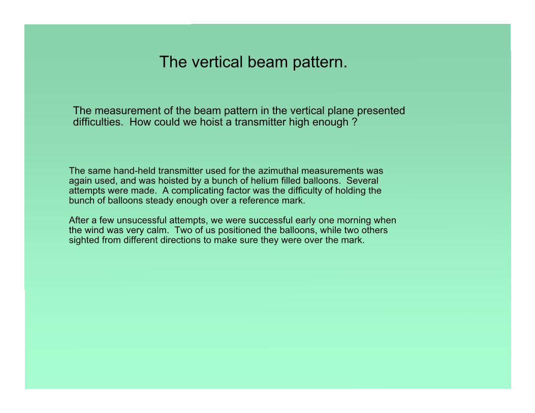
The vertical beam pattern.
The measurement of the beam pattern in the vertical plane presenteddifficulties. How could we hoist a transmitter high enough ?
The same hand-held transmitter used for the azimuthal measurements wasagain used, and was hoisted by a bunch of helium filled balloons. Severalattempts were made. A complicating factor was the difficulty of holding thebunch of balloons steady enough over a reference mark.
After a few unsucessful attempts, we were successful early one morning whenthe wind was very calm. Two of us positioned the balloons, while two otherssighted from different directions to make sure they were over the mark.

Left to right: Frank Ghigo (behind balloons), Grote Reber, Sandy Heatherly, Patrick Heatherly, Bob Vance,unidentified (behind Bob).
Preparing for the vertical beam measurement
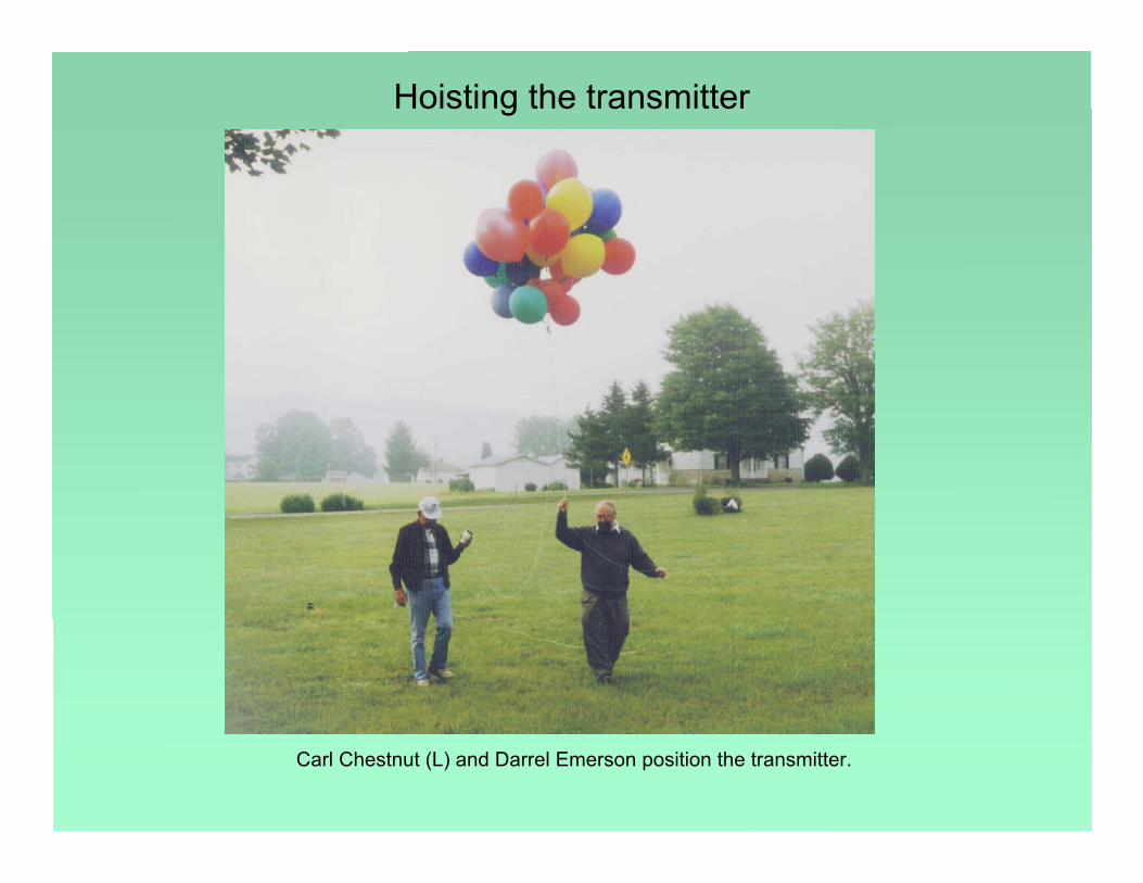
Hoisting the transmitter
Carl Chestnut (L) and Darrel Emerson position the transmitter.

Vertical beampattern:
calculated andmeasured.
Considering thedifficulties in positioningthe bunch of balloons,the measurements areprobably in sufficientlygood agreement with thecalculations.

Observing Method
The antenna makes a complete rotation every 20 minutes. Theobserving method that Jansky used, and that we also tried to use, wasto collect data continuously as the antenna rotated for several hours.
Rotations in azimuth producetracks in Right Ascension(RA) and Declination (Dec),similar to those shown here.

Sky sweeps, Galactic
Each 360 degree sweep in azimuth produces curves inGalactic Longitude and Latitude such as are shownhere.

Observing Session
Test observations were made on April 4-5, 1996. Theionospheric MUF was below about 8 MHz for thewhole session. Observing was very operator intensivebecause the chain had a tendency to slip off the gear,so had to be pushed into alignment frequently.
After two 20-minute rotations the feed cable had to bedisconnected and unwound. The dedicated grouptended the antenna over a 10 hour period, obtainingdata from 12 complete rotations of the antenna.
[This was before the mechanical improvementsdirected later in the summer by Reber.]
These plots show Amplitude vs Azimuth for twelverotations (2 per plot).
Possible interference, noted by arrows, comesalways at constant azimuth.
Strong variable interference at az=255 deg is fromthe direction of the Observatory kitchen, perhaps acycling refrigerator.
A more steady source at az=55 deg is from thedirection of the Director's residence.

Sky Image in RA/DEC coordinates
The all-sky image is madeby gridding the individualscans. The Galactic Planeshows clearly. Probableinterference sources areindicated below.

Contour Map in Galactic Coordinates

Comparison with Sullivan's analysis of Jansky's 1933 Observations
W. T. Sullivan has re-analyzed Jansky's 1933 data, estimated the brightness temperaturescale, and presented it as a contour diagram in Galactic Coordinates.
(see Sky&Telescope, Aug.1978, p.101; and "Classics in Radio Astronomy", Reidel 1982.)
This map shows Cass A as adistinct peak above the galacticbackground.
Our map shows no peak at theposition of Cass A, consistent withits flux decreasing with time.
Contours labelled in units of 1000 Kelvins.

Conclusions *The galaxy can be observed and mapped using the Jansky antenna replica. The observations are consistent with a significant decline in flux density of CAS-A over 60 years.
Future Work *With a goal of accurately mapping the sky at 20.5 MHz, we plan tomake several improvements.
Improvements to the chain drive alignment and addition of arotating coaxial joint will permit operation of the antenna withoutconstant operator attention.
Calibration procedures will be developed so that sky brightnesscan be measured accurately.
Correction for ionospheric refraction and absorption will beincluded in post-processing.
Additional observing sessions over the next year will help todistinguish interference from celestial sources.
* From the AAS poster presentation of June 1996.

So, what happened?
What can be said from a perspective 12 years later?
Nothing more happened after the summer of 1996. Why? Several reasons come to mind.
The only one of the items under "Future Work" that was accomplished was the installation of therotating coaxial joint and the improvements to the alignment of the chain and drive system. But evenwith those improvements, the chain slipped off the gear after a few hours. The alignment was neverimproved enough to allow continuous long-term trouble-free operation.
The goals of proper calibration and data processing procedures were never realized.
The end of the solar minimum meant that surveys of the galaxy were no longer possiblein the years following 1996.
It became clear that it was going to take a lot more effort to make the Jansky antenna easy touse and reliable. Combined with the problems with properly distinguishing the galaxy fromionosphere and local interference, the Janksy "Fellers" just ran out of steam and returned towork on more pressing matters.

References
By Karl G. Jansky . . . .
1932: "Directional Studies of Atmospherics at High Frequencies," Proc.IRE., vol.20, p.1920.1933: "Electrical Disturbances Apparently of Extraterrestrial Origin," Proc.IRE, vol.21, p.1387.1933: "Radio waves from outside the solar system", Nature, v132, p66.1933: "Electrical phenomena that apparently are of interstellar origin",
Popular Astronomy, v41, p.548, Dec.1933.1935: "A note on the source of interstellar interference", Proc.IRE, 23, p.1158.1937: "Minimum noise levels obtained on short-wave radio receiving systems", Proc.IRE, 25, p1517.
By Grote Reber ….
1988: "A play entitled the beginning of radio astronomy". J.Roy.Astron.Soc.Canada, v82, no.3, p.93.
By W. T. Sullivan:
1978: "A New Look at Karl Jansky's Original Data", Sky and Telescope. Aug.1978, p.101.
1982: "Classics in Radio Astronomy" Reidel. (Selection of historical radio astronomy papers.)