repairing and replacing evaporators ...applianceassistant.com/servicemanuals/4321963_r-83...2...
TRANSCRIPT
I
JOB AIDPart No. 4321963
CONSUMER SERVICES TECHNICAL
EDUCATION GROUP PRESENTS R-83
REPAIRING AND REPLACINGREPAIRING AND REPLACINGREPAIRING AND REPLACINGREPAIRING AND REPLACINGREPAIRING AND REPLACINGEVAPORATORSEVAPORATORSEVAPORATORSEVAPORATORSEVAPORATORS

II

III
INTRODUCTIONINTRODUCTIONINTRODUCTIONINTRODUCTIONINTRODUCTION“REPAIRING AND REPLACING EVAPORATORS”, Part No. 4321963, presents specific procedures
for repairing and replacing evaporators in Whirlpool top-mount, bottom-mount and side-by-side
refrigerator freezers with foamed-in-place heat exchangers.
GOALS AND OBJECTIVESGOALS AND OBJECTIVESGOALS AND OBJECTIVESGOALS AND OBJECTIVESGOALS AND OBJECTIVESThe goal of this Job Aid is to provide detailed instructions that will enable the service technician to
successfully perform repairs or replacement of evaporators with foamed-in-place heat exchangers.
The objectives of this Job Aid are:
The Service Technician will -
• Understand the proper safety precautions.
• Understand how to effectively protect the plastic freezer compartment liner from damage during
the repair process.
• Follow proper service procedures.
• Successfully return the refrigerator/freezer to proper operational status.
TO THE INSTRUCTOR/INDEPENDENTSTUDENT
This Job Aid is designed to be used with the video tape, “REPAIRING AND REPLACING
EVAPORATORS", Part No. 4321962. As you use this Job Aid you will see a symbol that looks like
this:
It instructs you to view certain sections of the video tape. The section numbers will appear in the
lower left corner of the screen.
This Job Aid contains “Confirmation of Learning Exercises” at the end of various sections. A symbol
that looks like this: ( ✎ ) indicates that a pencil or pen will be necessary to complete the exercise.
WHIRLPOOL CORPORATION ASSUMES NO RESPONSIBILITY
FOR ANY REPAIRS MADE ON OUR PRODUCTS BY ANYONE
OTHER THAN AUTHORIZED SERVICE TECHNICIANS.
© 1996 Whirlpool Corporation, Benton Harbor, Michigan
!!
IV
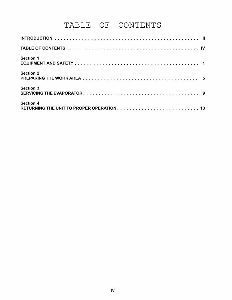
TABLE OF CONTENTSINTRODUCTION III
TABLE OF CONTENTS IV
Section 1
EQUIPMENT AND SAFETY 1
Section 2
PREPARING THE WORK AREA 5
Section 3
SERVICING THE EVAPORATOR 9
Section 4
RETURNING THE UNIT TO PROPER OPERATION 13○ ○ ○ ○ ○ ○ ○ ○ ○ ○ ○ ○ ○ ○ ○ ○ ○ ○ ○ ○ ○ ○ ○ ○ ○ ○ ○
○ ○ ○ ○ ○ ○ ○ ○ ○ ○ ○ ○ ○ ○ ○ ○ ○ ○ ○ ○ ○ ○ ○ ○ ○ ○ ○ ○ ○ ○ ○ ○ ○ ○ ○ ○ ○ ○
○ ○ ○ ○ ○ ○ ○ ○ ○ ○ ○ ○ ○ ○ ○ ○ ○ ○ ○ ○ ○ ○ ○ ○ ○ ○ ○ ○ ○ ○ ○ ○ ○ ○ ○ ○ ○ ○
○ ○ ○ ○ ○ ○ ○ ○ ○ ○ ○ ○ ○ ○ ○ ○ ○ ○ ○ ○ ○ ○ ○ ○ ○ ○ ○ ○ ○ ○ ○ ○ ○ ○ ○ ○ ○ ○ ○ ○ ○
○ ○ ○ ○ ○ ○ ○ ○ ○ ○ ○ ○ ○ ○ ○ ○ ○ ○ ○ ○ ○ ○ ○ ○ ○ ○ ○ ○ ○ ○ ○ ○ ○ ○ ○ ○ ○ ○ ○ ○ ○ ○ ○ ○
○ ○ ○ ○ ○ ○ ○ ○ ○ ○ ○ ○ ○ ○ ○ ○ ○ ○ ○ ○ ○ ○ ○ ○ ○ ○ ○ ○ ○ ○ ○ ○ ○ ○ ○ ○ ○ ○ ○ ○ ○ ○ ○ ○ ○ ○ ○ ○
1
!! View Section 1 of the Video Tape
Section One
EQUIPMENT AND SAFETYEQUIPMENT AND SAFETYEQUIPMENT AND SAFETYEQUIPMENT AND SAFETYEQUIPMENT AND SAFETYSAFETY
Electrical Shock HazardDisconnect power before servicing.
Failure to do so could result in serious injury or death.
▲! WARNING
Sealed System ServicingRepairing and replacing the evaporator in a refrigerator/freezer with a foamed-in-place heat exchanger
should be approached like any other typical sealed system repair. All equipment necessary to purge
refrigerant from the sealed system, recovering the refrigerant and performing sweep and final charge
procedures should be available.
Before any attempt is made to purge the sealed system, check the model/serial number plate located
inside the refrigerator for correct refrigerant and system charge.
EQUIPMENT
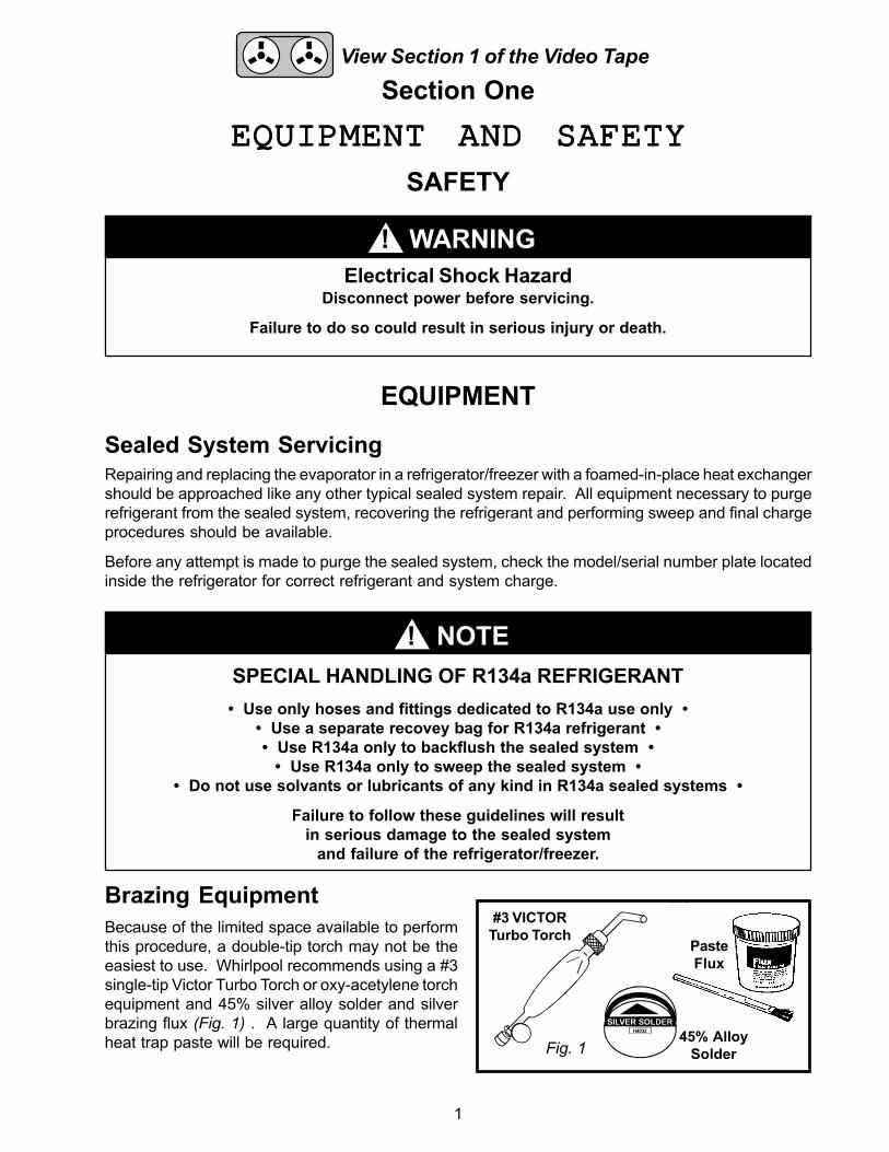
Because of the limited space available to perform
this procedure, a double-tip torch may not be the
easiest to use. Whirlpool recommends using a #3
single-tip Victor Turbo Torch or oxy-acetylene torch
equipment and 45% silver alloy solder and silver
brazing flux (Fig. 1) . A large quantity of thermal
heat trap paste will be required.
Brazing Equipment
▲! NOTE
#3 VICTOR
Turbo Torch
45% Alloy
Solder
Paste
Flux
Fig. 1
SPECIAL HANDLING OF R134a REFRIGERANT
• Use only hoses and fittings dedicated to R134a use only •
• Use a separate recovey bag for R134a refrigerant •
• Use R134a only to backflush the sealed system •
• Use R134a only to sweep the sealed system •
• Do not use solvants or lubricants of any kind in R134a sealed systems •
Failure to follow these guidelines will result
in serious damage to the sealed system
and failure of the refrigerator/freezer.
2
Evaporator Repair KitWhirlpool has developed a special Evaporator Repair Kit, Part No. 4387444, containing items unique
to this service procedure. This kit is available separately and should be ordered in addition to any
order for replacement component hook-up evaporators.
Fig. 2
Fig. 3
Heat Resistant Cardboard Shield - This specially designed corrugated cardboard shield is resistant
to radiated heat up to 350°F and will aid in protecting the plastic freezer compartment liner from
melting from the radiated heat of a torch. When properly installed, this material will create a tent that
will allow radiated heat to flow away from the brazing site. As the heat moves outward toward the
front of the compartment it will both cool and dissipate. THIS MATERIAL IS NOT FLAME RESISTANT.
It will burn if it comes in contact with an open torch flame.
Aluminum Adhesive Tape - Aluminum adhesive tape is provided to secure the heat resistant cardboard
shield inside the freezer compartment.
Flame Gard™ - A 9"x12" flame resistant shield consisting of a metal heat reflecting guard covered by
a non-asbestos flameproof backing will protect the plastic freezer compartment liner from burning or
melting from an open torch flame. When installed properly, the metal side of the shield will be placed
directly against the plastic freezer compartment liner and will act to reflect the heat from the torch
flame away from the plastic. The flame proof backing acts an insulator and will not burn. Extensive
field tests indicate that this shield will provide protection for a significant period of time. However,
periods of extremely long brazing times could cause the plastic freezer compartment liner to melt.
This damage will not be noticeable until the Flame Gard™ is removed. Similar circumstances could
cause the foam insulation surrounding the heat exchanger to vaporize or burn with an open flame.
Therefore, be as brief and efficient as possible whenever unbrazing or brazing any joint.
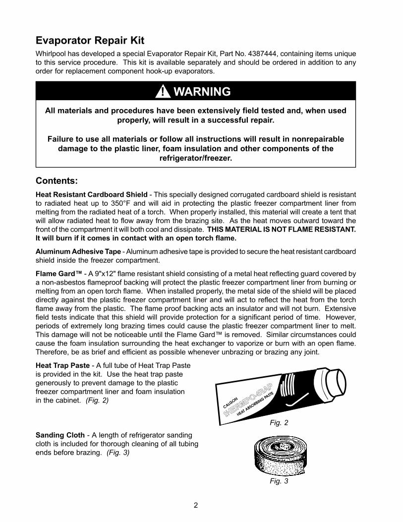
Heat Trap Paste - A full tube of Heat Trap Paste
is provided in the kit. Use the heat trap paste
generously to prevent damage to the plastic
freezer compartment liner and foam insulation
in the cabinet. (Fig. 2)
Sanding Cloth - A length of refrigerator sanding
cloth is included for thorough cleaning of all tubing
ends before brazing. (Fig. 3)
Contents:
▲! WARNING
All materials and procedures have been extensively field tested and, when used
properly, will result in a successful repair.
Failure to use all materials or follow all instructions will result in nonrepairable
damage to the plastic liner, foam insulation and other components of the
refrigerator/freezer.
3
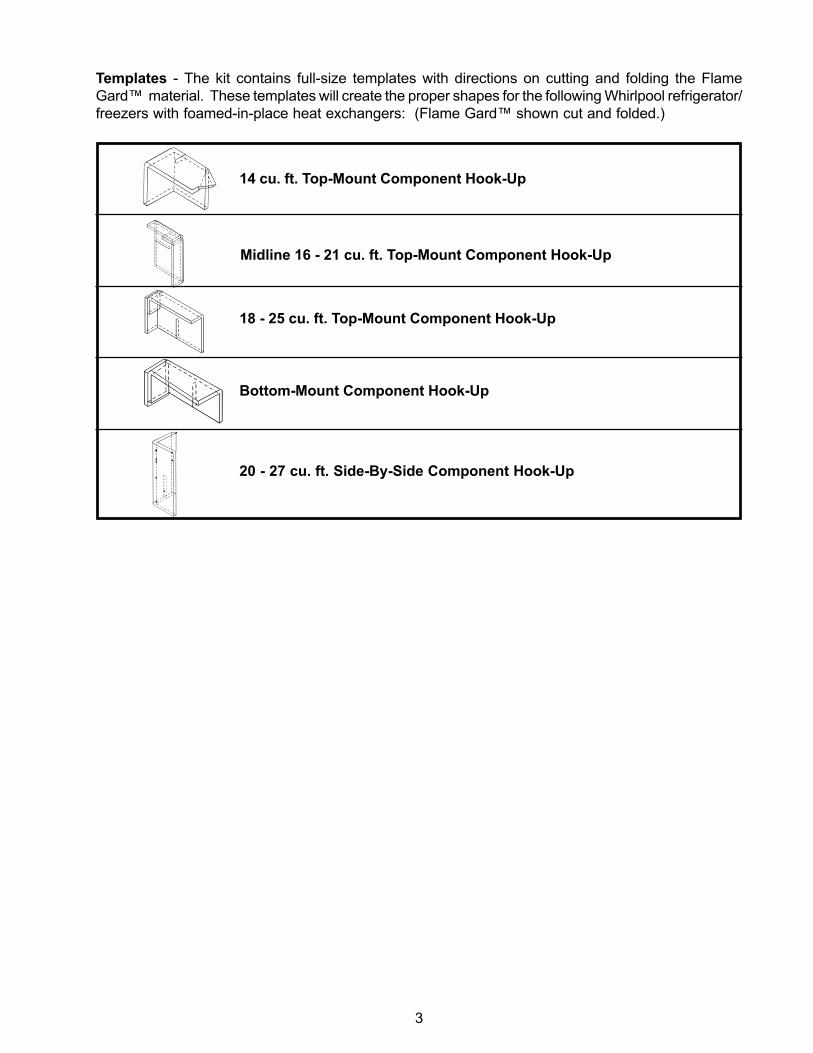
Templates - The kit contains full-size templates with directions on cutting and folding the Flame
Gard™ material. These templates will create the proper shapes for the following Whirlpool refrigerator/
freezers with foamed-in-place heat exchangers: (Flame Gard™ shown cut and folded.)
14 cu. ft. Top-Mount Component Hook-Up
20 - 27 cu. ft. Side-By-Side Component Hook-Up
Bottom-Mount Component Hook-Up
Midline 16 - 21 cu. ft. Top-Mount Component Hook-Up
18 - 25 cu. ft. Top-Mount Component Hook-Up

4
NOTESNOTESNOTESNOTESNOTES

5
!! View Section 2 of the Video Tape
Section Two
1. Purge and recover refrigerant from the sealed system.
2. Unplug the unit from the wall receptacle.
3. Remove all contents of the freezer and the automatic ice maker, if present. Remove the fill tube extension
from inside the freezer compartment.
4. If not foamed-in-place, remove the screws securing the water inlet tube to the rear of the unit and pull the
tube out from the back.
5. Remove freezer sub-floor on top mount units.
6. On 14 cu. ft. models: Remove the air tower.
7. Remove the screw securing the ice maker access cover to the evaporator wall and remove the ground wire
clipped to the evaporator cover.
8. Remove the two screws securing the evaporator cover to the fan assembly.
9. Remove the screws securing the evaporator cover to the back of the freezer.
10. Remove the evaporator cover.
11. Remove screws securing the evaporator fan assembly to the back of the freezer.
12. Disconnect the main wiring harness plug from the cabinet connector.
13. Remove the evaporator fan assembly from the freezer section.
14. Unwrap the sound deadening material from the evaporator inlet. Keep it in one piece. It will need to be
reinstalled later.
15. Cut away the foam stop material even with the plastic freezer compartment liner where the heat
exchanger emerges from the cabinet. (Fig. 4)
PREPARING THE WORK AREAPREPARING THE WORK AREAPREPARING THE WORK AREAPREPARING THE WORK AREAPREPARING THE WORK AREAThe following instructions for preparing the worksite are very important. Careful attention to details at
this point in the procedure will help insure a successful job. Illustration in this section are based on 14
cu. ft. top-mount component hook-up refrigerator/freezers.
Fig. 4
6
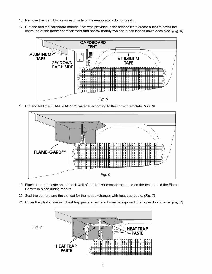
16. Remove the foam blocks on each side of the evaporator - do not break.
17. Cut and fold the cardboard material that was provided in the service kit to create a tent to cover the
entire top of the freezer compartment and approximately two and a half inches down each side. (Fig. 5)
18. Cut and fold the FLAME-GARD™ material according to the correct template. (Fig. 6)
19. Place heat trap paste on the back wall of the freezer compartment and on the tent to hold the Flame
Gard™ in place during repairs.
20. Seal the corners and the slot cut for the heat exchanger with heat trap paste. (Fig. 7)
21. Cover the plastic liner with heat trap paste anywhere it may be exposed to an open torch flame. (Fig. 7)
Fig. 5
Fig. 6
Fig. 7
7
(((((✎✎ ✎✎ ✎ ) CONFIRMATION OF LEARNING) CONFIRMATION OF LEARNING) CONFIRMATION OF LEARNING) CONFIRMATION OF LEARNING) CONFIRMATION OF LEARNING
The following list contains the 21 step to PREPARING THE WORK SITE. Number them in the correct
order.
__ Cover the plastic liner with heat trap paste anywhere it may be exposed to an open torch
flame.
__ If not foamed-in-place, remove the screws securing the water inlet tube to the rear of the unit and
pull the tube out from the back.
__ Cut away the foam stop material even with the plastic freezer compartment liner where the heat
exchanger emerges from the cabinet.
__ Remove the evaporator cover.
__ Remove freezer sub-floor on top mount units.
__ Remove the screw securing the ice maker access cover to the evaporator wall and remove the
ground wire clipped to the evaporator cover.
__ Unplug the unit from the wall receptacle.
__ Disconnect the main wiring harness plug from the cabinet connector.
__ Remove the screws securing the evaporator cover to the back of the freezer.
__ Cut and fold the cardboard material that was provided in service kit to create a tent to cover the
entire top of the freezer compartment and approximately two and a half inches down each side.
__ Remove the two screws securing the evaporator cover to the fan assembly.
__ On 14 cu. ft. models: Remove the air tower.
__ Seal the corners and the slot cut for the heat exchanger with heat trap paste.
__ Place heat trap paste on the back wall of the freezer compartment and on the tent to hold the
Flame Gard™ in place during repairs.
__ Unwrap the sound deadening material from the evaporator inlet. Keep it in one piece. It will need
to be reinstalled later.
__ Remove screws securing the evaporator fan assembly to the back of the freezer.
__ Remove the evaporator fan assembly from the freezer section.
__ Purge and recover refrigerant from the sealed system.
__ Remove all contents of the freezer and the automatic ice maker, if present. Remove the fill tube
extension from inside the freezer compartment.
__ Remove the foam blocks on each side of the evaporator - do not break.
__ Cut and fold the FLAME-GARD™ material according to the correct template.

8
NOTESNOTESNOTESNOTESNOTES
9
!! View Section 3 of the Video Tape
Section Three
SERVICING THE EVAPORATORSERVICING THE EVAPORATORSERVICING THE EVAPORATORSERVICING THE EVAPORATORSERVICING THE EVAPORATORRepairs
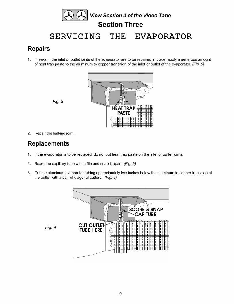
1. If leaks in the inlet or outlet joints of the evaporator are to be repaired in place, apply a generous amount
of heat trap paste to the aluminum to copper transition of the inlet or outlet of the evaporator. (Fig. 8)
2. Repair the leaking joint.
Replacements
1. If the evaporator is to be replaced, do not put heat trap paste on the inlet or outlet joints.
2. Score the capillary tube with a file and snap it apart. (Fig. 9)
3. Cut the aluminum evaporator tubing approximately two inches below the aluminum to copper transition at
the outlet with a pair of diagonal cutters. (Fig. 9)
Fig. 8
Fig. 9

10
4. Remove the evaporator from the freezer compartment.
5. Carefully unbraze the transition from the suction line.
6. Take the time to repack fresh heat trap paste on any areas where it may have dried out. Heat trap paste
is only effective when moist.
7. Insert the copper suction line tubing into the outlet of the new evaporator approximately one half inch.
8. Insert the capillary tube approximately one inch into the inlet of the new evaporator.
9. Hang the new evaporator on the flanges in the back wall of the freezer compartment.
10. Apply a generous amount of heat trap paste to the aluminum to copper transition of the inlet and
outlet of the evaporator. (Fig. 10)
11. Braze the outlet joint first.
12. Braze the inlet joint next.
13. Inspect the newly brazed joints for black spots indicating potential leaks. Rebraze if necessary.
14. Do not remove the FLAME-GARD™ or cardboard tent at this time.
Fig. 10
11
(((((✎✎ ✎✎ ✎ ) CONFIRMATION OF LEARNING) CONFIRMATION OF LEARNING) CONFIRMATION OF LEARNING) CONFIRMATION OF LEARNING) CONFIRMATION OF LEARNINGPlace the letter in the blank to the left of the number that best completes the following statements.
__ 1. When repairing a leak in the inlet or outlet of the evaporator:
a) Cut the transition out of the line and replace it.
b) Apply a generous amount of heat trap paste around the transition.
c) Do not install the Flame Gard™ heat shield.
d) b and c are correct.
__ 2. Whirlpool recommends the use of the following tools to repair or replace an evaporator:
a) A double-tip acetylene torch
b) A #3 single-tip Victor Turbo Torch
c) Oxy-acetylene torch equipment
d) b and c are correct
__ 3. The recommended brazing material(s) for this procedure is:
a) 15% Silver Alloy
b) 45% Silver Alloy with Silver Brazing Flux
c) 45% Silver Alloy
d) 5% Silver Alloy
__ 4. The recommended order for brazing the joints when replacing the evaporator is:
a) There is not specific order.
b) Braze the inlet first, then the outlet.
c) Braze the outlet first then the inlet.
d) Braze the joint closest to you.
__ 5. When brazing is complete:
a) Remove the Flame Gard™ heat shield and cardboard tent.
b) Check for leaks with a mirror and rebraze if necessary.
c) Proceed to Sweep Procedure.
d) Check for leaks with a mirror and rebraze if necessary, then proceed to Sweep Procedure.

12
NOTESNOTESNOTESNOTESNOTES
13
!! View Section 4 of the Video Tape
Section Four
RETURNING THE UNIT TORETURNING THE UNIT TORETURNING THE UNIT TORETURNING THE UNIT TORETURNING THE UNIT TOPROPER OPERATIONPROPER OPERATIONPROPER OPERATIONPROPER OPERATIONPROPER OPERATION
1. Perform Sweep Charge Procedure.
2. Before circulating the sweep charge, thoroughly leak check the newly brazed joints with bubble solution
and correct any leaks.
3. Final charge the sealed system and check that refrigerator/freezer is operating properly.
4. Remove the FLAME-GARD™ and cardboard tent.
5. Remove all heat trap paste from the freezer compartment.
6. Reassemble the components in the freezer compartment.
14
ANSWERS TO CONFIRMATIONANSWERS TO CONFIRMATIONANSWERS TO CONFIRMATIONANSWERS TO CONFIRMATIONANSWERS TO CONFIRMATIONOF LEARNINGOF LEARNINGOF LEARNINGOF LEARNINGOF LEARNING
Section Two
21. Cover the plastic liner with heat trap paste anywhere it may be exposed to an open torch flame.
4. If not foamed-in-place, remove the screws securing the water inlet tube to the rear of the unit and
pull the tube out from the back.
15. Cut away the foam stop material even with the plastic freezer compartment liner where the heat
exchanger emerges from the cabinet.
10. Remove the evaporator cover
5. Remove freezer sub-floor on top mount units.
7. Remove the screw securing the ice maker access cover to the evaporator wall and remove the
ground wire clipped to the evaporator cover.
2. Unplug the unit from the wall receptacle.
12. Disconnect the main wiring harness plug from the cabinet connector.
9. Remove the screws securing the evaporator cover to the back of the freezer.
17. Cut and fold the cardboard material that was provided in service kit to create a tent to cover the
entire top of the freezer compartment and approximately two and a half inches down each side.
8. Remove the two screws securing the evaporator cover to the fan assembly.
6. On 14 cu. ft. models: Remove the air tower.
20. Seal the corners and the slot cut for the heat exchanger with heat trap paste.
19. Place heat trap paste on the back wall of the freezer compartment and on the tent to hold the
Flame Gard™ in place during repairs.
14. Unwrap the sound deadening material from the evaporator inlet. Keep it in one piece. It will need
to be reinstalled later.
11. Remove the screws securing the evaporator fan assembly to the back of the freezer.
13. Remove the evaporator fan assembly from the freezer section.
1. Purge and recover refrigerant from the sealed system.
3. Remove all contents of the freezer and the automatic ice maker, if present. Remove the fill tube
extension from inside the freezer compartment.
16. Remove the foam blocks on each side of the evaporator - do not break.
18. Cut and fold the FLAME-GARD™ material according to the correct template.
1. b 2. d 3. b 4. c 5. d
Section Three
15
PRODUCT SPECIFICATIONSPRODUCT SPECIFICATIONSPRODUCT SPECIFICATIONSPRODUCT SPECIFICATIONSPRODUCT SPECIFICATIONSA N DA N DA N DA N DA N D
WARRANTY INFORMATION SOURCESWARRANTY INFORMATION SOURCESWARRANTY INFORMATION SOURCESWARRANTY INFORMATION SOURCESWARRANTY INFORMATION SOURCESFOR PRODUCT SPECIFICATIONS AND WARRANTY INFORMATION CALL:
FOR ROPER PRODUCTS: 1-800-447-6737
FOR WHIRLPOOL PRODUCTS: 1-800-253-1301
FOR KITCHENAID PRODUCTS: 1-800-422-1230
FOR TECHNICAL ASSISTANCE WHILE AT THE CUSTOMER'S HOME CALL:
THE TECHNICAL ASSISTANCE LINE: 1-800-253-2870Have your store number ready to identify you as an Authorized Servicer

1
INSTRUCTION SHEETfor Repairing and Replacing
Evaporators
▲! WARNINGElectrical Shock Hazard
Disconnect power before servicing.
Failure to do so could result in
serious injury or death.
7. Remove the screw securing ice maker access
cover to evaporator wall and remove the ground
wire clipped to the evaporator cover.
8. Remove the two screws securing the evaporator
cover to the fan assembly.
9. Remove the screws securing the evaporator
cover to the back of the freezer.
10. Remove the evaporator cover.
11. Remove screws securing the evaporator fan
assembly to the back of the freezer.
12. Disconnect the main wiring harness plug from the
cabinet connector.
13. Remove the evaporator fan assembly from the
freezer section.
14. Unwrap the sound deadening material from the
evaporator inlet. Keep it in one piece. It will
need to be reinstalled later.
15. Cut away the foam stop material even with the
plastic freezer compartment liner where the heat
exchanger emerges from the cabinet. (Fig. 1)
CONTENTS OF REPAIR KIT
1. One (1) Heat resistant cardboard to protect
plastic freezer liner from radiant heat.
2. One (1) 9"x12" FLAME-GARD™ flame resistant
pad to protect plastic freezer liner from open
flame.
3. One (1) Tube of heat trap paste.
4. One (1) Strip of adhesive backed aluminum tape
to attach heat resistant cardboard to inside of
freezer compartment.
5. One (1) Strip of refrigeration sanding cloth.
6. Five (5) Templates to custom cut and fold the
FLAME-GARD™ flame resistant pad to fit
various refrigerator/freezer models.
7. One (1) Instruction Sheet.
PREPARING THE WORKSITE
1. Purge and recover refrigerant from the system.
2. Unplug the unit from the wall receptacle
3. Remove screws securing water inlet tube to the
rear of the unit and pull tube out from the back.
4. Remove all contents of the freezer and the
automatic ice maker, if present.
5. Remove freezer sub-floor on top mount units.
6. On 14 cu. ft. models: Remove the air tower.Fig. 1
Instruction Sheet 4387443 1/96© Whpl. Corporation 1996
(All Rights Reserved)
This repair kit can be used on all Top-Mount, Bottom-Mount, Side-By-Side and Mid-Line Refrigerator/Freezers.
All figures on this Instruction Sheet are based on a 14 cu. ft. Top-Mount model.
NOTE: It may be helpful to remove the freezer door if it is hinged on the same side as the evaporator heat
exchanger entrance.
2
16. Remove the foam blocks on each side of the
evaporator - do not break.
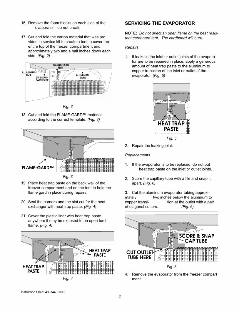
17. Cut and fold the carton material that was pro
vided in service kit to create a tent to cover the
entire top of the freezer compartment and
approximately two and a half inches down each
side. (Fig. 2)
18. Cut and fold the FLAME-GARD™ material
according to the correct template. (Fig. 3)
Fig. 3
Fig. 3
19. Place heat trap paste on the back wall of the
freezer compartment and on the tent to hold the
flame gard in place during repairs.
20. Seal the corners and the slot cut for the heat
exchanger with heat trap paste. (Fig. 4)
21. Cover the plastic liner with heat trap paste
anywhere it may be exposed to an open torch
flame. (Fig. 4)
Fig. 4
SERVICING THE EVAPORATOR
NOTE: Do not direct an open flame on the heat resis-
tant cardboard tent. The cardboard will burn.
Repairs
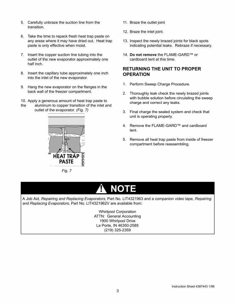
1. If leaks in the inlet or outlet joints of the evapora-
tor are to be repaired in place, apply a generous
amount of heat trap paste to the aluminum to
copper transition of the inlet or outlet of the
evaporator. (Fig. 5)
Fig. 5
2. Repair the leaking joint.
Replacements
1. If the evaporator is to be replaced, do not put
heat trap paste on the inlet or outlet joints.
2. Score the capillary tube with a file and snap it
apart. (Fig. 6)
3. Cut the aluminum evaporator tubing approxi-
mately two inches below the aluminum to
copper transi- tion at the outlet with a pair
of diagonal cutters. (Fig. 6)
Fig. 6
4. Remove the evaporator from the freezer compart
ment.
Instruction Sheet 4387443 1/96
3
5. Carefully unbraze the suction line from the
transition.
6. Take the time to repack fresh heat trap paste on
any areas where it may have dried out. Heat trap
paste is only effective when moist.
7. Insert the copper suction line tubing into the
outlet of the new evaporator approximately one
half inch.
8. Insert the capillary tube approximately one inch
into the inlet of the new evaporator.
9. Hang the new evaporator on the flanges in the
back wall of the freezer compartment.
10. Apply a generous amount of heat trap paste to
the aluminum to copper transition of the inlet and
outlet of the evaporator. (Fig. 7)
11. Braze the outlet joint
12. Braze the inlet joint.
13. Inspect the newly brazed joints for black spots
indicating potential leaks. Rebraze if necessary.
14. Do not remove the FLAME-GARD™ or
cardboard tent at this time.
RETURNING THE UNIT TO PROPER
OPERATION
1. Perform Sweep Charge Procedure.
2. Thoroughly leak check the newly brazed joints
with bubble solution before circulating the sweep
charge and correct any leaks.
3. Final charge the sealed system and check that
unit is operating properly.
4. Remove the FLAME-GARD™ and cardboard
tent.
5. Remove all heat trap paste from inside of freezer
compartment before reassembling.
Instruction Sheet 4387443 1/96
Fig. 7
A Job Aid, Repairing and Replacing Evaporators, Part No. LIT4321963 and a companion video tape, Repairing
and Replacing Evaporators, Part No. LIT4321962V are available from:
Whirlpool Corporation
ATTN: General Accounting
1900 Whirlpool Drive
La Porte, IN 46350-2585
(219) 325-2359
▲! NOTE

V