repair instructions rotina 35 / 35 r - ozark biomedical · • 12 v dc supply for the cb (only...
TRANSCRIPT

09.05 Andreas Hettich GmbH & Co. KG AR026GB
Repair instructions
ROTINA 35 / 35 R

2/51
Andreas Hettich GmbH & Co. KG Föhrenstraße 12, D-78532 Tuttlingen / Germany Phone (07461) 705-0 Fax (07461) 705-125 [email protected], [email protected] www.hettichlab.com
© 1999 by Andreas Hettich GmbH & Co. KG
All rights reserved. No part of this publication may be reproduced without the written prior permission of the copyright owner.
Modifications reserved!
AR026GB / 09.05

3/51
Contents
1. Introduction ............................................................................................................7
2. Description of the new Hettich centrifuges .........................................................8
2.1 Functional structure of the ROTINA 35 / 35 R...................................................8
2.2 Control panel (CP) ............................................................................................8
2.3 Supply board (SB).............................................................................................9
2.4 Frequency converter (FC) .................................................................................9
2.5 Special features ..............................................................................................10
2.6 Motor / Tacho system......................................................................................10
2.7 Imbalance switch.............................................................................................11
2.8 Interlocking......................................................................................................11
2.9 Cooling............................................................................................................11 2.9.1 Temperature sensor B1, in the centrifuge chamber .................................11 2.9.2 Function of the cooling board (CB) A3 .....................................................11
2.10 Fan..................................................................................................................11
2.11 Offset calibration .............................................................................................12
2.12 Protection........................................................................................................12
3. Troubleshooting procedures ..............................................................................13
4. Error messages ....................................................................................................14
4.1 Brief description ..............................................................................................14
4.2 Description and elimination of errors...............................................................16
5. Settings and interrogations.................................................................................24
5.1 Control panel...................................................................................................24
5.2 Procedure for initialization...............................................................................24
5.3 Imbalance Mode..............................................................................................25
5.4 OFFSET alignment .........................................................................................25 5.4.1 OFFSET value .........................................................................................26 5.4.2 Procedure for performing an OFFSET alignment.....................................26 5.4.3 Note for temperature sensor in centrifuge chamber.................................26
5.5 Parameter interrogation ..................................................................................27
5.6 Acoustic signal ................................................................................................27
5.7 Hours of operation...........................................................................................27
5.8 Checking the motor slippage...........................................................................28

4/51
5.9 Setting display contrast on control panel ........................................................ 28
5.10 Imbalance switch-off ....................................................................................... 29
6. Functional check after a repair........................................................................... 30
7. Assembling and disassembling components ................................................... 30
7.1 Speed sensor B3 (speedometer) .................................................................... 33
7.2 Motor M1 / Vibration damper .......................................................................... 33
7.3 FC (frequency converter) ................................................................................ 33
7.4 SB (supply board) ........................................................................................... 33
7.5 CB A3 (cooling board) only ROTINA 35 R...................................................... 33
7.6 CP A4 (control panel) ..................................................................................... 34
7.7 EPROM at CP................................................................................................. 34
7.8 CC (control cables) ......................................................................................... 34
7.9 LL (Y1) (lid locking)......................................................................................... 34
7.10 BR R1 (brake resistor) .................................................................................... 34
7.11 Radio interference suppression filter Z1 ......................................................... 34
7.12 Mains choke coil (L1)...................................................................................... 35 7.12.1 Assembly and disassembly ..................................................................... 35 7.12.2 Short the mains choke coil....................................................................... 35
7.13 Mains switch Q1 ............................................................................................. 35
7.14 Appliance plug B1, overvoltage protection F1................................................. 36
7.15 Imbalance switch ............................................................................................ 36
7.16 Fan M5 for the motor (only ROTINA 35 R) ..................................................... 36
7.17 Temperature sensor B1 in centrifuge chamber............................................... 36
7.18 Temperature sensor B2 at condenser ............................................................ 36
7.19 Fan M3 and M4............................................................................................... 36
7.20 Compressor (M2)............................................................................................ 37
7.21 Gas filled damper............................................................................................ 37
8. Speedometer-code-position of the rotors ......................................................... 38

5/51
9. Circuit diagrams...................................................................................................40
9.1 Mains supply with supply board (SB) 230 V....................................................40
9.2 Mains supply with supply board (SB) 115 V....................................................41
9.3 Circuit diagram supply board (SB) ..................................................................42
9.4 Connecting diagram and component layout supply board (SB) ......................43
9.5 Signals at control cable (between CP-SB) ......................................................44
9.6 Block diagram control panel (CP)....................................................................45
9.7 Connecting diagram Control board (CP) .........................................................46
9.8 Block diagram and control panel signals at FC ...............................................47
9.9 Connecting diagram frequency converter (FC) ...............................................48
9.10 Circuit diagram cooling board .........................................................................49
9.11 Connecting diagram and component layout cooling board .............................50
10. Technical specifications ..................................................................................51

6/51
Abbreviations
CP Control panel FC Frequency converter SB Supply board CB Cooling board CC Control cable LL Lid locking BC Braking chopper BR Brake resistor MR Mains reset,
mains switch OFF - ON EC Error cause ES Error consequence ER Error remedy M Measurements
ECR Error-code reset

7/51
1. Introduction • Repairs must only be carried out by personnel authorised to do so by the
manufacturer.
Interventions and modifications at centrifuges, which have been conducted by persons not authorized by the HETTICH company, are at their own risk and entail the loss off all guarantee and liability claims. In such an event any guarantee claim or liability claim against the HETTICH company expire.
• Only original spare parts and original accessories licensed by the Hettich company are allowed to be utilised.
If no original spare parts or no original accessories are used, any guarantee claim or liability claim against the HETTICH company ceases to exist.
• Information about the operation of the centrifuge please see operating instructions. • We reserve all rights for these technical documents.

CP : control panel, FC : frequency converter, SB : supply board, CB : cooling board, CC : control cable, LL : lid locking, BC : braking chopper, BR : brake resistor, MR : mains reset, EC : error cause, ES : error consequence, ER : error remedy, M : measurements, ECR : error-code reset
8/51
2. Description of the new Hettich centrifuges 2.1 Functional structure of the ROTINA 35 / 35 R These microprocessor-controlled centrifuges are comprised of the following electrical components:
• Control panel (CP), microprocessor-controlled
• Supply board (SB)
• Frequency converter (FC, motor control), microprocessor-controlled
• Motor with speed sensor (speedometer)
• Braking chopper (BC) with brake resistor (BR)
• Lid locking (LL)
• Cooling board (CB), only Rotina 35 R 2.2 Control panel (CP) The CP is the ”brain” or ”master” of the centrifuge. Via a serial data bus system, the MASTER controls its SLAVE, the component:
− frequency converter (FC) The individual tasks of the CP are:
• Management of operator inputs and control of LCD display. • Storage of 3 run programs. • Control of components:
− FC via the enabling circuit and via the serial interface. − cooling and fan.
• Evaluation of the speed sensor (speedometer). • Evaluation of the imbalance switch. • Evaluation of the FC fault alarm circuit. • Evaluation of the LL open/closed signalling circuit. • Control of the relay for the LL solenoid at rotor standstill • Temperature measurement and sensor evaluation of the temperature sensor in
centrifuge chamber (only refrigerated centrifuge). • Routine for input, storage and transfer of temperature offset values. • Format of the serial interface: - 5 Volt interface with 3 conductors. - (16-pole control cable, pole 6, 8 and 11).
• The CP is powered from the SB via the control cable: + 10...15 Volt pole 1,2 GND pole 15,16

CP : control panel, FC : frequency converter, SB : supply board, CB : cooling board, CC : control cable, LL : lid locking, BC : braking chopper, BR : brake resistor, MR : mains reset, EC : error cause, ES : error consequence, ER : error remedy, M : measurements, ECR : error-code reset
9/51
2.3 Supply board (SB) The SB performs the following individual functions: • 12 V DC and 5 V DC supply for the SB. • 12 V DC supply for the CP. • 12 V DC supply for the CB (only Rotina 35 R). • Plugging station X5 for mains power supply, LL magnet and transmission of the
signalling circuit for LL-switch (open/closed over opto-coupler to the CP). • Power supply for speed sensor (speedometer). • Plugging station X4 for speed sensor cable an0d transmission to the CP and FC. • Control of the relay for the LL solenoid at rotor standstill • Plugging station X3 for the imbalance switch and direct transmission of the
imbalance signal to the CP. • The 5 Volt interface with 3 conductors is converted to an RS 485 interface with 2
conductors: - Interface to FC: RS 485-interface via 2 conductors. • Transfer of primary enabling (=Hardware STOP) CP ⇒ FC • Transfer of fault circuit (FC-ERROR) FC ⇒ CP 2.4 Frequency converter (FC) The FC performs the following individual functions: • Generation of the motor power supply.
(3-phase AC current of variable frequency and voltage) Mode of operation: The mains supply is rectified, smoothed and chopped in three
bridge elements to give a pulse-duration modulated supply. • Monitoring of the motor current. • Evaluation of the overtemperature switch in the motor (only version 115V, AC). • Slave behaviour (handling of interrogations and commands from the CP via the serial
interface): RS 485-interface with 2 conductors (10-pole control cable, pole 3 and 5).
• Evaluation of the primary enabling (Hardware STOP) for the FC (10-pole control cable, pole 7).
• Evaluation of potential faults and monitoring of the fault circuit (FC-ERROR) (10-pole control cable, pole 4).
• The electrical power, which resulted from braking, will be conducted to the BR. The braking chopper switches at a voltage:
− from approximately 390V (230V series). − from approximately 200V (115V series).
• The BR is protected by an overtemperature switch. At a short circuit on the BC, which is located on the FC, the BR overheats because of high current. The overtemperature switch cuts off the voltage supply from the FC. After cooling down at the BR the voltage supply is switched on again.

CP : control panel, FC : frequency converter, SB : supply board, CB : cooling board, CC : control cable, LL : lid locking, BC : braking chopper, BR : brake resistor, MR : mains reset, EC : error cause, ES : error consequence, ER : error remedy, M : measurements, ECR : error-code reset
10/51
• The CP issues the following via the serial interface:
− Speed − Starting and braking levels − Control commands START, BRAKE, STOP
• State display by LED´s: In standby mode the green LED is on In running mode the green LED is on In fault mode the green LED flashes If the FC processor detects a fault, it shuts down itself automatically and triggers the fault circuit (FC-ERROR). The CP then interrogates the type of fault via the serial interface. 2.5 Special features • Multiprocessor concept:
Although one microprocessor will fail, the other one will continue to monitor its assigned area. If the CP fails, the drive will be shut down automatically by the FC when no inter-rogations have been received via the interface for more than 30 seconds.
• Interface concept: Transmission of data is monitored by an extra check sum.
• Hardware concept: All switches with a safety relevant function are of the NC-contact type, which means that loose contacts and open-circuit faults can also be detected.
2.6 Motor / Tacho system • The motor is a 3 phase asynchronous motor with 2 pairs of poles. • A speed sensor (speedometer) attached to the motor receives the following from the
transmitter attached to the rotor, − rotor code information (see section "8") and − speed data (6 pulses per revolution)
• The ACTUAL speed is monitored and controlled via the CP
− Double safety: The FC is also programmed that no value of speed in excess of the maximum permitted rotor speed can be selected. The FC monitors the speed and switches off at excess speed with error code “ERROR 84”.
• Rotor standstill is monitored via the CP. − The lid can only be opened when the CP has detected standstill.

CP : control panel, FC : frequency converter, SB : supply board, CB : cooling board, CC : control cable, LL : lid locking, BC : braking chopper, BR : brake resistor, MR : mains reset, EC : error cause, ES : error consequence, ER : error remedy, M : measurements, ECR : error-code reset
11/51
2.7 Imbalance switch • A switch detects any imbalance. • Imbalance can only be detected in running mode (starting, centrifuging and braking). • If any imbalance is detected, the drive is changed over to braking. 2.8 Interlocking • Opening of the LL is prevented by a latch. The LL can only be opened when the relay
on the SB is energized by the CP. This occurs when the rotor is at standstill and mains power is applied. A solenoid is energized and releases the latch.
• The centrifuge can only be started when the lid is closed. A microswitch on the LL detects the position of the LL.
2.9 Cooling • Temperature behaviour:
− When rotor is at standstill and the lid is locked, the cooling is operating. − When rotor is at standstill and the lid is unlocked, there is no cooling.
2.9.1 Temperature sensor B1, in the centrifuge chamber • This temperature is processed in the CP. • The housing of the temperature sensor B1 also contains an overtemperature switch.
In refrigerated centrifuges this switch cuts off the drive at > 60°C. 2.9.2 Function of the cooling board (CB) A3 • Plugging station (X3) for the temperature sensor and the overtemperature switch in
the centrifuge chamber. • The voltage of the temperature sensor in the centrifuge chamber plug X4 being
transmitted over a 10-pole CC to the CP plug X101. • The signal of the overtemperature switch in the centrifuge chamber plug X4 being
onward transmitted over a 10-pole CC to the CP plug X101. • Plugging station (X2) for the overheating protection B2 at the condenser. • Relay circuit for the compressor and the fan. The overheating protection B2 at the
condenser is series connected to the relay voltage. • Plugging station (X1) for the compressor and the fan. 2.10 Fan • The fans cool down the refrigerant flowing through the condenser. • The fans are parallel-connected to the compressor.

CP : control panel, FC : frequency converter, SB : supply board, CB : cooling board, CC : control cable, LL : lid locking, BC : braking chopper, BR : brake resistor, MR : mains reset, EC : error cause, ES : error consequence, ER : error remedy, M : measurements, ECR : error-code reset
12/51
2.11 Offset calibration • Offset calibration is performed in order to equalize the tolerances of the temperature
sensor and the electronics.
Perform Offset calibration when replacing:
Where/How
− the temperature sensor calibrate the temperature sensor. − the CP calibrate temperature sensor and read out the old
offset values and put them in the new CP. − the CP-EPROM Read out the old offset values and put them in the
new CP. 2.12 Protection Mains power input ⇒ Mains input with overvoltage protection Mains switch ⇒ Thermal overload protection (fuse) FC ⇒ Electronic protection Motor ⇒ Overtemperature cutout > 135°C (only 115 V
version). Cooling ⇒ Overtemperature switch in centrifuge chamber and
at condenser.

CP : control panel, FC : frequency converter, SB : supply board, CB : cooling board, CC : control cable, LL : lid locking, BC : braking chopper, BR : brake resistor, MR : mains reset, EC : error cause, ES : error consequence, ER : error remedy, M : measurements, ECR : error-code reset
13/51
3. Troubleshooting procedures • Fuses in installation in which centrifuge is installed are intact. • Supply voltage present at (see circuit diagram): − Connecting cable − Appliance plug − Overvoltage protection (F1) − Mains switch (Q1) − Supply board, plug X5 (PIN 1, PIN 5). • Look for the displayed error code in the chapter "Error messages". • Remedy the error according to the instructions. • Carry out a functional check after every repair and whenever a component is
replaced, see chapter "Functional check after a repair".

CP : control panel, FC : frequency converter, SB : supply board, CB : cooling board, CC : control cable, LL : lid locking, BC : braking chopper, BR : brake resistor, MR : mains reset, EC : error cause, ES : error consequence, ER : error remedy, M : measurements, ECR : error-code reset
14/51
4. Error messages 4.1 Brief description • Error messages in: ROTINA 35 ROTINA 35 R
Error designation No. Brief description Page
TACHO-ERROR 01 Speedometer pulses break down during rotation 16 TACHO-ERROR 02 No speedometer pulses after start command 16
IMBALANCE Imbalance on motor axle 17 CONTROL-ERROR 04 LL error, lid opened without recognizing that
motor had stopped 17
N > MAX 05 Excessive speed error, 250 RPM above n-max of rotor
17
ROTORCODE 10 Invalid rotor code 18 MAINS INTERRUPT Mains interruption 18 VERSION-ERROR 12 Error in initialization 18
N < MIN 13 Speed error, slippage is too great 19
CONTROL-ERROR 21 CP - error: speed 19 CONTROL-ERROR 22 CP - error: I²C bus 19 CONTROL-ERROR 23 CP - error: display memory 19 CONTROL-ERROR 24 CP - error: clock timeout 19 CONTROL-ERROR 25 CP - error: EEPROM 19 CONTROL-ERROR 26 CP - error: driver defective 19 N > ROTOR MAX --- CP - error: nominal speed is higher
than permitted rotor speed or nominal RCF is higher than permitted rotor RCF
19
SER I/O-ERROR 30 No connection between CP and serial interface 19 SER I/O-ERROR 31 No connection between FC and serial interface 19 SER I/O-ERROR 33 Subassembly data incorrectly transmitted 20 SER I/O-ERROR 34 Data incorrectly transmitted between CP and FC 20 SER I/O-ERROR 36 No acknowledgement (NAK) from FC to CP 20

CP : control panel, FC : frequency converter, SB : supply board, CB : cooling board, CC : control cable, LL : lid locking, BC : braking chopper, BR : brake resistor, MR : mains reset, EC : error cause, ES : error consequence, ER : error remedy, M : measurements, ECR : error-code reset
15/51
Error designation No. Brief description Page
No cooling (No error displayed)
Overtemperature at condenser 20
°C / *-ERROR 52 Overtemperature in centrifuge chamber 21 °C / *-ERROR 53 Temperature sensor in centrifuge chamber is
defective 21
FU/CCI-ERROR 60 Faulty release signal to FC 21 FU/CCI-ERROR 61 FC - error: computing section 22 FU/CCI-ERROR 62 FC - error: undervoltage 22 FU/CCI-ERROR 63 FC - error: overcurrent 22 FU/CCI-ERROR 64 FC - error: overvoltage 22 FU/CCI-ERROR 67 FC - error: overtemperature in motor
(only 115V) 23
FU/CCI-ERROR 68 FC - error: overtemperature in FC 23 FU/CCI-ERROR 69 FC - error: EEPROM 23 FU/CCI-ERROR 84 FC - error: FC recognizes excess speed 23 FU/CCI-ERROR 85 FC - error: “Watchdog” in FC had
triggered 23

CP : control panel, FC : frequency converter, SB : supply board, CB : cooling board, CC : control cable, LL : lid locking, BC : braking chopper, BR : brake resistor, MR : mains reset, EC : error cause, ES : error consequence, ER : error remedy, M : measurements, ECR : error-code reset
16/51
4.2 Description and elimination of errors TACHO - ERROR 01
EC During centrifugation the speedometer pulses are interrupted. ES The rotor slows down until it stops.
After the rotor stops, there is a DC braking for 30 sec. An MR during slowing-down causes a DC braking for 3 min. After the DC braking, the ”open the lid” release takes place. Further cooling to NOMINAL temperature.
ER • Speed sensor (speedometer) defective or loose contact on plug. Measure speedometer pulses on plug X4 / SB (pin 4 - pin 2).
• CC to CP, or CC to FC is defective. • SB or CP or FC is defective.
M Also see at SB-X4 and CP-X1 (PIN 14) and FC S501 (PIN 8) ECR Open the lid. Turn the rotor by hand and perform an MR while the rotor
is turning. TACHO - ERROR 02
EC There are no speedometer pulses on the CP after startup. ES The rotor slows down until it stops.
After the rotor stops, there is a DC braking for 30 sec. An MR during slowing-down causes a DC braking for 3 min. After the DC braking, the ”open the lid” release takes place. Further cooling to NOMINAL temperature.
ER • Startup took place without the rotor. • Motor not connected. • Motor is defective. • Speed sensor (speedometer) defective, or loose contact on plug.
Measure speedometer pulses on plug X4 / SB (pin 4 - pin 2). • CC to CP, or CC to FC is defective. • No release signal to FC. • SB or CP or FC is defective.
M Also see at SB-X4 and CP-X1 (PIN 14) and FC S501 (PIN 8) ECR Open the lid. Turn the rotor by hand and perform an MR while the rotor
is turning.

CP : control panel, FC : frequency converter, SB : supply board, CB : cooling board, CC : control cable, LL : lid locking, BC : braking chopper, BR : brake resistor, MR : mains reset, EC : error cause, ES : error consequence, ER : error remedy, M : measurements, ECR : error-code reset
17/51
IMBALANCE
EC Imbalance on motor axle. ES The centrifuge slows down until the “open the lid” release occurs.
Further cooling until NOMINAL temperature is reached. ER • Weight difference in rotor components.
• Supporting lugs not lubricated. • False IMBALANCE MODE is set (see chapter "Imbalance Mode"). • Imbalance switch not connencted. • Imbalance switch is defective. • Loose contact in cable or plug. • CC to CP is defective. • CP or SB is defective.
M Also see at SB-X3 and CP-X1 (PIN 12) ECR Perform an MR.
CONTROL - ERROR 04
EC LL is open during centrifugation. ES Slowing down until the ”open the lid” release occurs.
Further cooling until NOMINAL temperature is reached. ER • LL is defective and can be opened during centrifugation.
• Loose contact in cable or in plug. • CC to CP is defective. • CP or SB is defective.
M Also see at SB-X5 (PIN 2 and PIN 6) and CP-X1 (PIN 5) ECR Perform an MR.
N > MAX 05
EC Excess speed. The speed recognized by the speed sensor (speedometer) is 250 RPM greater than the n-max speed of the rotor.
ES The centrifuge slows down until the ”open the lid” release occurs. Further cooling until NOMINAL temperature is reached.
ER • Insulation of speed sensor (speedometer) cable is defective. • Loose contact on speed sensor (speedometer) cable. • Speed sensor (speedometer) is defective. • CC to CP is defective. • CP or FC or SB is defective.
ECR Perform an MR.

CP : control panel, FC : frequency converter, SB : supply board, CB : cooling board, CC : control cable, LL : lid locking, BC : braking chopper, BR : brake resistor, MR : mains reset, EC : error cause, ES : error consequence, ER : error remedy, M : measurements, ECR : error-code reset
18/51
ROTORCODE 10
EC An invalid rotor code was read during startup. ES The centrifuge slows down until the ”open the lid” release occurs.
Further cooling until NOMINAL temperature is reached. ER • Magnetic coding on rotor is defective.
• Speedometer system is defective. • Loose contact on speed sensor (speedometer) plug • The rotation of the rotor (direction) is incorrect.
M Also see section 10. ECR Open the lid or perform an MR.
MAINS INTERRUPT
EC Interruption of mains supply during centrifugation. ES The centrifuge slows down until the ”open the lid” release occurs.
− Switching on at the mains during centrifugation causes slowing-down until the ”open the lid” release occurs.
− Switching on at the mains when the rotor has stopped brings about the ”open the lid” release.
ER • Power supply has failed. • Loose contact in electrical connections. • CC to CP is defective.
ECR Open the lid and press the . key.
This error cannot be reset by an MR
VERSION - ERROR 12
EC Differences in the initialization from CP (EPROM) or FC. ES No further user operation is possible. ER • An incorrect EPROM has been plugged into CP. M Also see initialization section 5.2
ECR Perform an MR.

CP : control panel, FC : frequency converter, SB : supply board, CB : cooling board, CC : control cable, LL : lid locking, BC : braking chopper, BR : brake resistor, MR : mains reset, EC : error cause, ES : error consequence, ER : error remedy, M : measurements, ECR : error-code reset
19/51
N < MIN 13
EC Insufficient speed; the slippage of the motor is too great. The centrifuge regulation can adjust the speed by 5% max (the limit of adjustment). The error is indicated if the ACTUAL speed is lower than the NOMINAL speed minus 5%.
ES The centrifuge slows down until the ”open the lid” release occurs. Further cooling until NOMINAL temperature is reached
ER • Motor is labouring (damage to bearings). • Motor has a short-circuited coil (coil is defective). • Loose contact in the electrical connections. • FC is defective.
Release signal to FC was interrupted during centrifugation. ECR Open the LL. Perform an MR.
CONTROL - ERROR 21 - 26
EC Internal error in CP. ES The centrifuge slows down until the ”open the lid” release occurs. ER • CP is defective.
ECR Perform an MR. N > ROTOR MAX
EC Error in the entered program ES Further operation is not possible. ER SET speed or SET RCF is higher than the permissible rotor speed or
permissible rotor RCF. ECR Open the lid.
Reduce the speed or RCF in the entered program to the permissible rotor speed or permissible rotor RCF.
SER I/O - ERROR 30 and ERROR 31
EC CP has no connection to the component FC via serial interface. ES The centrifuge slows down until the ”open the lid” release occurs. ER • CC to FC is defective.
• There is no voltage on FC. • F2 overtemperature switch on brake resistor has opened or is not
connected. • CP or FC is defective. • Cable on plug S102 is not or wrong plugged
ECR Perform an MR.

CP : control panel, FC : frequency converter, SB : supply board, CB : cooling board, CC : control cable, LL : lid locking, BC : braking chopper, BR : brake resistor, MR : mains reset, EC : error cause, ES : error consequence, ER : error remedy, M : measurements, ECR : error-code reset
20/51
SER I/O - ERROR 33
EC CP is not receiving correct data from FC. ES The centrifuge slows down until the ”open the lid” release occurs. ER • CC to FC is defective.
• CP or FC is defective. ECR Perform an MR.
SER I/O - ERROR 34
EC CP is not receiving correct data from FC. ES The centrifuge slows down until the ”open the lid” release occurs.
Further cooling until NOMINAL temperature is reached. ER • CC to FC is defective.
• CP or FC is defective. ECR Perform an MR.
SER I/O - ERROR 36
EC FC sends signal NAK to the CP after receiving an unknown command. NAK (not acknowledged).
ES The centrifuge slows down until the ”open the lid” release occurs. Further cooling until NOMINAL temperature is reached.
ER • CC to FC is defective. • FC is defective. • CP is defective.
ECR Perform an MR. °C / * - NO COOLING
EC No cooling in centrifuge chamber. Overtemperature at condenser, temperature > 60°C.
ES Cooling switches off. Continuance of centrifugation until temperature switch in the centrifuge chamber triggers and “ERROR 52” appears. The centrifuge slows down until the “open the lid” release occurs.
ER • Condenser soiled. • Loose contact in plug. • SB is defective. • Fan is defective. • Sensor cable B2 is defective.
M Also see at CB-X2 ECR Perform an MR.

CP : control panel, FC : frequency converter, SB : supply board, CB : cooling board, CC : control cable, LL : lid locking, BC : braking chopper, BR : brake resistor, MR : mains reset, EC : error cause, ES : error consequence, ER : error remedy, M : measurements, ECR : error-code reset
21/51
°C / * - ERROR 52
EC Overtemperature in centrifuge chamber. ES The centrifuge slows down until the ”open the lid” release occurs. ER • Sensor cable B1 is defective.
• Loose contact in plug. • CP is defective. • CB is defective.
M Also see at CB-X3 (PIN 1 and PIN 2) and CP-X101 (PIN 4) ECR Perform an MR.
°C / * - ERROR 53
EC Temperature sensor in centrifuge chamber has a short circuit or a dis-continuity.
ES The centrifuge slows down until the ”open the lid” release occurs. Cooling switches off.
ER • Temperature sensor is defective. • Sensor cable B1 is defective. • Loose contact in plug. • CP is defective. • CB is defective.
M Also see at CB-X3 (PIN 5 and PIN 4), CP-X101 (PIN 8) ECR Perform an MR.
FU / CCI - ERROR 60
EC The release signal was not correctly transmitted to FC. The evaluation of the release signal only occurs once after MR.
ES No further user operation is possible. ER • CC to FC is defective.
• CC to CP is defective. • SB is defective.
M Also see at CP-X1 (PIN 4) and FC-S501 (PIN 7).

CP : control panel, FC : frequency converter, SB : supply board, CB : cooling board, CC : control cable, LL : lid locking, BC : braking chopper, BR : brake resistor, MR : mains reset, EC : error cause, ES : error consequence, ER : error remedy, M : measurements, ECR : error-code reset
22/51
General Notice for FU / CCI - ERROR 61 to FU / CCI - ERROR 69
ES ECR M
• FC switches independently. • The rotor freewheels, coasting. • No further user operation is possible. • Cooling continues until nominal value is attained • Mains switch is OFF. • Switch mains switch to ON after 1 min. • Also see at FC-S501 (PIN 4) and CP-X1 (PIN 13).
FU / CCI - ERROR 61
EC Error in computing section. ER • CC is defective.
• FC is defective. FU / CCI - ERROR 62
EC Undervoltage. Mains voltage less than 20% as nominal voltage. ER • Supply voltage too low, see chapter "Short the mains choke coil".
• CC is defective. • FC is defective.
M Also see at FC, UDC. FU / CCI - ERROR 63
EC Overcurrent. ER • Short circuit in motor.
• Motor impedance is too low. • CC is defective. • FC is defective.
FU / CCI - ERROR 64
EC Voltage in intermediate circuit: >410 V DC at 230 V >205 V DC at 115 V This error normally only occurs when the drive is being braked.
ER • BR is defective. • CC is defective. • FC is defective.
M Also see at FC, UDC.

CP : control panel, FC : frequency converter, SB : supply board, CB : cooling board, CC : control cable, LL : lid locking, BC : braking chopper, BR : brake resistor, MR : mains reset, EC : error cause, ES : error consequence, ER : error remedy, M : measurements, ECR : error-code reset
23/51
FU / CCI - ERROR 67
EC Only centrifuges with 115 V. Overtemperature in the motor. The cable “overtemperature” in the motor has high impedance.
ER • Overtemperature switch opens because of overtemperature in the motor
• CC is defective. • FC is defective. • Motor is defective
M Also see at FC, remove plug S2 and measure at the plug Switch closed: ≈ 0 Ω • opened: ∞ Ω
FU / CCI - ERROR 68
EC Overtemperature in FC. ER • Insufficient heat abduction from FC to centrifuge housing. There is
no, or not enough, heat-conducting paste between FC and housing.• Full-load operation and an ambient temperature > 45°C. • CC is defective. • FC is defective.
FU / CCI - ERROR 69
EC EEPROM in FC is defective. ER • CC is defective.
• FC is defective FU / CCI - ERROR 84
EC FC recognizes excess speed. During rotation the speedometer pulses (6 per revolution) are controlled by the FC. The FC switches the centrifuge off, when the maximum speed of the rotor is exeeded more than 500 rpm.
ER • CCis defective. • FC is defective.
M Also see at SB-X4 and FC S501 (PIN 8). FU / CCI - ERROR 85
EC “Watchdog” in FC Discrepancy in program procedure
ER • CC is defective. • FC is defective.

CP : control panel, FC : frequency converter, SB : supply board, CB : cooling board, CC : control cable, LL : lid locking, BC : braking chopper, BR : brake resistor, MR : mains reset, EC : error cause, ES : error consequence, ER : error remedy, M : measurements, ECR : error-code reset
24/51
5. Settings and interrogations 5.1 Control panel
START
RCF
IMPULS
STOP
T / °C >RCF< RPM t / min:s
PROG
T / °CT / °CT / °CPROG
The EPROM of the CP must, in all circumstances, correspond to the machine version and the cooling version.
5.2 Procedure for initialization An initialization must be carried out:
• after replacing the FC.
The frequency converter must be adjusted to the centrifuge. Requirement: 1. Rotor has stopped. 2. LL is open. 3. Mains switch is OFF. 4. Plug on coding strip X3 on the CP has a a jumper in slot 3 and
in slot 4 (initialization position). • Mains switch is ON → Display: INIT - MODE
• Press key → Display: VERS 15 °C / * 01 ↑ ↑
machine version Cooling version (01 = with cooling, 00 = without cooling)
• Press the key → Display: IMBALANCE MODE 2
• Press the or key to set IMBALANCE MODE 1 or IMBALANCE MODE 2. Now press the START key to save this setting. Information about IMBALANCE MODE see chapter "Imbalance Mode".
• Press key → Display: PARAM - INIT 0000 ↑ ↑
machine version Number of initializations

CP : control panel, FC : frequency converter, SB : supply board, CB : cooling board, CC : control cable, LL : lid locking, BC : braking chopper, BR : brake resistor, MR : mains reset, EC : error cause, ES : error consequence, ER : error remedy, M : measurements, ECR : error-code reset
25/51
• Press START key → Display: *** OK *** and then: PARAM - INIT F001
↑ ↑machine version
Number of initializations
• Mains switch is OFF. • Remove both jumpers from slot 3 and slot 4 on coding strip X3 on the CP.
Put a jumper on slot zero at the plug on coding strip X3 on the CP. (Service position, “Watchdog”)
An initialization is always necessary after a replacement of the FC. 5.3 Imbalance Mode From programme version 3.00 it is necessary to set the imbalance mode during the initialization. Depending on the SB version IMBALANCE MODE 1 or IMBALANCE MODE 2 must be selected.
If the incorrect imbalance mode is selected, the display shows error "IMBALANCE" permanently !
5.4 OFFSET alignment An OFFSET alignment is performed to align the temperature sensor and the CP electro-nics with one another. An alignment must be performed in any event:
− 1. Replacement of the temperature sensor at the centrifuge chamber. − 2. Replacement of the CP or the EPROM at the CP.
The OFFSET alignment for the temperature sensor is carried out in the CP. To carry out an offset compensation, measure the temperature directly on the temperature sensor with a temperature measuring device. Then enter the measured value in the display and save it.
Each correction must be confirmed by the START key.
Requirements: 1. Rotor has stopped. 2. LL is open. 3. Mains switch is OFF. 4. Plug on coding strip X3 at the CP the jumper from slot 0 to slot 3
(OFFSET position).

CP : control panel, FC : frequency converter, SB : supply board, CB : cooling board, CC : control cable, LL : lid locking, BC : braking chopper, BR : brake resistor, MR : mains reset, EC : error cause, ES : error consequence, ER : error remedy, M : measurements, ECR : error-code reset
26/51
5.4.1 OFFSET value The OFFSET value is the difference between the actual temperature and the sensor temperature. Example: Actual temperature - Sensor temperature = OFFSET value
25.5 °C - 27.0 °C = -1.5 °C 5.4.2 Procedure for performing an OFFSET alignment
1. Mains switch is ON → Display: * OFFSET – MODE * 2. Press key → Display: T1: 27,0 °C → 25,5 °C
↑ ↑
Sensor temperature Actual temperature
3. The sensor temperature measured is to be adjusted with the keys to make it agree with the actual temperature.
4. Press the START key → Display: *** OK *** If the temperature settings are not confirmed by pressing the START key, the old settings will be maintained.
5. Mains switch is OFF. 6. Remove jumper from slot 3 on coding strip X3 on the CP.
Put the jumper on slot zero at the plug on coding strip X3 on the CP (Service position, “Watchdog”).
5.4.3 Note for temperature sensor in centrifuge chamber If the temperature in the sample deviates from the nominal value (Display), the offset alignment can be altered as follows:
− Actual temperature is lower than nominal temperature: Set the offset temperature of T1 lower by the amount of the deviation (the cor-rected value is lower).
− Actual temperature is higher than nominal temperature: Set the offset temperature of T1 higher by the amount of the deviation.

CP : control panel, FC : frequency converter, SB : supply board, CB : cooling board, CC : control cable, LL : lid locking, BC : braking chopper, BR : brake resistor, MR : mains reset, EC : error cause, ES : error consequence, ER : error remedy, M : measurements, ECR : error-code reset
27/51
5.5 Parameter interrogation Requirements: 1. Rotor is stopped. 2. Mains switch is ON. Keep key pressed down until (after about 8 sec) the following appears in the display:
1. SOUND / BELL ON1 or OFF (acoustic signal) Press key. Every time the key is pressed, the display alters as follows:
2. CONTROL XXXXX h Hours of operation 3. VERS XX °C / * XX Machine version, cooling version 4. FU / CCI - 1000 FC type 5. FU / CCI - S. 00.XX FC software
If nothing more is keyed in for 8 sec, the CP switches over to normal mode. Only Nos. 1. and 2. of the function retrievals listed here can be altered. 5.6 Acoustic signal The acoustic signal sounds: • Upon the appearance of a disturbance in 2 second intervals. • After completion of a centrifugation run and rotor standstill in 30 second intervals. The acoustic signal is stopped by opening the lid or pressing any key. The signal can be activated or deactivated after completion of the centrifugation run (if the rotor is at standstill) in the following manner: • Hold down the key for 8 seconds.
After 8 seconds, SOUND / BELL XXX appears in the display. • Set OFF or ON1 with the key or . • Press the key START in order to store the setting.
As confirmation, ∗∗∗ ok ∗∗∗ will be displayed for a short period. 5.7 Hours of operation You can check and change the working hours only if the rotor is at standstill.
• Keep the key pressed for 8 seconds. After 8 seconds, SOUND / BELL XXX will be displayed.
• Press the key again. The working hours (CONTROL: ) of the centrifuge will be displayed.
• To exit the working hours check screen, press the or key. Press the RCF key to set the working hours.
• Set the working hours with the and keys. • Press the START key to save the setting.
∗∗∗ ok ∗∗∗ is displayed for a short time to confirm that the setting has been saved.

CP : control panel, FC : frequency converter, SB : supply board, CB : cooling board, CC : control cable, LL : lid locking, BC : braking chopper, BR : brake resistor, MR : mains reset, EC : error cause, ES : error consequence, ER : error remedy, M : measurements, ECR : error-code reset
28/51
5.8 Checking the motor slippage The centrifuge control can readjust the speed depending on the rotor. The error (N < MIN 13) is displayed if the rotor speed (ACTUAL speed) is lower than the permitted range of control. It is only possible to check the slippage during a centrifugation run. • Start a centrifugation run and wait until the set speed is achieved. • Keep the key pressed for 8 seconds. After 8 seconds the following appears in the
display:
PROG >RCF< RPM t/minT/°C
Rotor speed Field speed Slippage = (field speed) - (rotor speed)
• Press the key to exit the slippage display. 5.9 Setting display contrast on control panel The display contrast has been preset at the factory, but can be readjusted. Requirements: The control panel is at room temperature (20 ... 25°C). The contrast must be adjusted so that the background pixels are not visible. Adjustment: Using a screwdriver, adjust the contrast on the trimming potentiometer on the rear side of the control section (see diagram). Rear side of control panel:
4000 4100

CP : control panel, FC : frequency converter, SB : supply board, CB : cooling board, CC : control cable, LL : lid locking, BC : braking chopper, BR : brake resistor, MR : mains reset, EC : error cause, ES : error consequence, ER : error remedy, M : measurements, ECR : error-code reset
29/51
5.10 Imbalance switch-off The permissible imbalance is specified for rotor 1724 by the indication of the difference in weight of opposite rotor positions. When having a difference in weight within the range of 15g to 30g during run-up, the drive has to switch off before reaching 1500 RPM. The imbalance switch-off is adjusted by changing the distance of the imbalance switch. With a test run with the indicated differences in weight the imbalance switch-off will be checked. Adjusting the imbalance switch:
• Loosen both screws at the angle bracket of the imbalance switch on the outer part of the housing floor until you can shift it.
• Set the permissible imbalance by shifting the angle bracket. • Tighten both screws at the angle bracket of the imbalance switch again. • Check the imbalance switch-off with a test run.

CP : control panel, FC : frequency converter, SB : supply board, CB : cooling board, CC : control cable, LL : lid locking, BC : braking chopper, BR : brake resistor, MR : mains reset, EC : error cause, ES : error consequence, ER : error remedy, M : measurements, ECR : error-code reset
30/51
6. Functional check after a repair After a repair a functional check of the unit must be carried out. For functional check a test run with the loaded rotor must be performed. During the test run the followings must be checked:
• Function of the keys, the display and the LEDs. • Run-up and slow-down time, max. speed of the rotor. Values see operating
instructions chapter "Anhang/Appendix, Rotoren und Zubehör/Rotors and accessories".
• Sample temperature. Values see operating instructions chapter "Anhang/Appendix, Rotoren und Zubehör/Rotors and accessories".
• Imbalance switch-off. Values see repair instructions chapter "Imbalance switch-off". • Current consumption. Values see repair instructions chapter "Technical
specifications". After the test run a safety test must be carried out. Check the following values:
• Insulation resistance > 2 MΩ • Protective conductor resistance < 0.2 Ω • Leakage current < 3.5 mA * * limit according to EN 61010 A laboratory centrifuge do not belong to those medical appliances which may be tested according to the regulation IEC 601 or corresponding national medical electronic standards. Laboratory centrifuges are classified as laboratory equipment. The regulations applying to laboratory equipment are IEC 1010 or European standard EN 61010. 7. Assembling and disassembling components Before assembling or disassembling components, the working processes in Tabelle 7-B for ROTINA 35 and ROTINA 35 R must first be carried out to reach the components and make a note of the plug numbers. The components are assembled in reverse order ! The further procedure is described on the following pages.

CP : control panel, FC : frequency converter, SB : supply board, CB : cooling board, CC : control cable, LL : lid locking, BC : braking chopper, BR : brake resistor, MR : mains reset, EC : error cause, ES : error consequence, ER : error remedy, M : measurements, ECR : error-code reset
31/51
In Tabelle 7-A the components are ordered in the following sequence:
Column 1: Abreviation Column 2: Components Column 3: Abreviations in the circuit diagrams Column 4: Plug connections Column 5: Connections at the electronic-panels Column 6: Described in capture.
Tabelle 7-A
1 2 3 4 5 6 A Speed sensor (speedometer) B3 X4 A1 7.1 B Motor M1 S101 A2 7.2 C Vibration damper 7.2 D FC (frequency converter) A2 7.3 E EPROM (on FC) A2 7.3 F SB (supply board) A1 7.4 G CB (cooling board) A3 7.5 H CP (control panel) A4 7.6 I EPROM (on CP) A4 7.7 J Mains choke coil - 7.12 K CC (control cables) - 16 conductors A4-A1 7.8 - 10 conductors A1-A2 - 10 conductors A4-A3
L LL (lid locking) Y1 X5 A1 7.9 M BR (brake resistor) R1 P10-P1 A2 7.10 N Radio interference suppression filter Z1 X5-Q1 A1 7.11 O Mains switch ON / OFF Q1 Z1-F1 7.13 P Appliance plug B4 F1 7.14 Q Overvoltage protection F1 B4-Q1 7.14 R Imbalance switch S1 X3 A1 7.15 S Fan for motor M5 X6 A1 7.16 T Temperature sensor (centrifuge chamber) B1 X3 A3 7.17 U Temperature sensor (condenser) B2 X2 A3 7.18 V Fan (compressor) M3 X1 A3 7.19 W Compressor M2 X1 A3 7.20 X Gas-filled damper 7.21

CP : control panel, FC : frequency converter, SB : supply board, CB : cooling board, CC : control cable, LL : lid locking, BC : braking chopper, BR : brake resistor, MR : mains reset, EC : error cause, ES : error consequence, ER : error remedy, M : measurements, ECR : error-code reset
32/51
Tabelle 7-B
Working processes A B C D E F G H I K L M N O P Q R S T U V W X1. Open lid X X X X X X X X2. Set mains switch to
OFF X X X X X X X X X X X X X X X X X X X X X
3. Disconnect centrifuge from mains voltage
X X X X X X X X X X X X X X X X X X X X X
4. Disassemble rotor X X X X X X 5. Remove motor
covering in centrifuge chamber
X X X X X X
6. Take rubber sleeve under motor covering out
X X X X X
7. Detach front screen X X X X X X X X X X X X X X X X X X X 8. Pull of theControl
cable from the CP X X X X X X X X X X X X X X X X X X X
9. Remove front screen
X X X X X X X X X X X X X X X X X X
10. Detach rear covering
X X X X
Example: Disassembling appliance plug 1. Definite the abreviaton of the appliance plug in Tabelle 7-A, column 1. Appliance plug = P 2. See Tabelle 7-B column P and carry out the working processes in numeric order. 3. Definite in Tabelle 7-A the corresponding abreviaton, for the example line P and pick out in column 6 the especially capture (9.13), where the disassembly is discribed.

CP : control panel, FC : frequency converter, SB : supply board, CB : cooling board, CC : control cable, LL : lid locking, BC : braking chopper, BR : brake resistor, MR : mains reset, EC : error cause, ES : error consequence, ER : error remedy, M : measurements, ECR : error-code reset
33/51
7.1 Speed sensor B3 (speedometer) • Unscrew speed sensor (speedometer) from upper end plate of motor. • Unplug plug number X4 from Supply board A1. • Replace speed sensor (speedometer). 7.2 Motor M1 / Vibration damper • Unscrew speed sensor (speedometer) from upper end plate of motor, and place it in
centrifuge chamber. • Pull out the 3 cables from plug S101 at the FC (BU/BN/BK). • Use a socket spanner to loosen and remove the three fastening nuts on lower end
plate of motor. • Lift motor upwards out of centrifuge. Unplug the earth lead. • Before motor is installed, the three vibration dampers must be checked for possible
wear or cracks, and if necessary replaced. • Replace the motor. • Care must be taken of the anti-twist device when the vibration dampers are being
installed. 7.3 FC (frequency converter) • Pull all plugs out of FC. • Unscrew from below the four fastening screws of FC. • Unscrew the screws on the connecting clips and pull the cables out. • Replace FC • Before installation, it must be noted that there is a heat-conducting paste between FC
and centrifuge housing floor.
Heat conducting from FC to centrifuge housing floor must be ensured.
7.4 SB (supply board) • All plugs on the SB must be pulled out. • Unscrew the four screws, and take SB out of centrifuge. • Replace SB 7.5 CB A3 (cooling board) only ROTINA 35 R • All plugs on the CB must be pulled out. • Unplug the two cables (RD and BK) at the SB. • Unscrew the four fastening screws at the CB. • Replace the CB.

CP : control panel, FC : frequency converter, SB : supply board, CB : cooling board, CC : control cable, LL : lid locking, BC : braking chopper, BR : brake resistor, MR : mains reset, EC : error cause, ES : error consequence, ER : error remedy, M : measurements, ECR : error-code reset
34/51
7.6 CP A4 (control panel) • Detach the two holding frames at the CP. • Lift out the CP on the opening at the front screen. • Replace the CP. 7.7 EPROM at CP • Pull the EPROM carefully out of IC-socket. • Pay attention to the polarity of the EPROM when installing. • Do not bend the IC-pins.
Before touching the EPROM ensure that your own static electricity is discharged.
• Replace the EPROM. 7.8 CC (control cables) • Unplug the corresponding control cable from the boards. • Replace the control cable. 7.9 LL (Y1) (lid locking) • Remove the front panel. • Unplug all cable from the lid lock. • Loosen the to fastening screws on the to of the housing. • Exchange the lid lock. 7.10 BR R1 (brake resistor) • From below loosen the two fastening screws of the BR at the floor. • Unplug the cables at the BR and the FC. • Loosen cable of overtemperature switch on the BR at FC (clip S102, position U1). • Replace BR. 7.11 Radio interference suppression filter Z1 • From below unscrew the two fastening screws of the radio interference suppression
filter. • Remove the plugs from the radio interference suppression filter. • Replace the radio interference suppression filter.

CP : control panel, FC : frequency converter, SB : supply board, CB : cooling board, CC : control cable, LL : lid locking, BC : braking chopper, BR : brake resistor, MR : mains reset, EC : error cause, ES : error consequence, ER : error remedy, M : measurements, ECR : error-code reset
35/51
7.12 Mains choke coil (L1) 7.12.1 Assembly and disassembly • Pull both plugs from the mains choke coil. • Undo the fastening screws of the mains choke coil. • Replace the mains choke coil. 7.12.2 Short the mains choke coil
In countries, in which the European standard EN 61000-3-2 applies it is not allowed to short the mains choke coil. The mains choke coil reduces the mains input current below the limit values stated in the above mentioned European standard.
If the centrifuge is run with undervoltage, that is mains frequency 50 Hz with a voltage < 205 V or mains frequency 60 Hz with a voltage < 210 V the voltage drop of the mains choke coil can cause the error FU / CCI - ERROR 62. The short of the mains choke coil will increase the supply voltage of the frequency converter.
• Pull both plugs (A) from the mains choke coil, see Figure 1. • Cut off both plugs and connect the ends of both cables together with a luster terminal
(B), see Figure 2.
Figure 1 Figure 2 7.13 Mains switch Q1 • Press mains switch out of lower part of housing. • Remove all plugs at mains switch. • Replace mains switch.
AB

CP : control panel, FC : frequency converter, SB : supply board, CB : cooling board, CC : control cable, LL : lid locking, BC : braking chopper, BR : brake resistor, MR : mains reset, EC : error cause, ES : error consequence, ER : error remedy, M : measurements, ECR : error-code reset
36/51
7.14 Appliance plug B1, overvoltage protection F1 • Remove mains switch, see chapter 7.13. • Unscrew the two fastening screws at the appliance plug. • Pull the appliance plug out of the opening. • Remove the overvoltage protection from the appliance plug. • Replace appliance plug. • Unplug the cables at the overvoltage protection. • Replace overvoltage protection. 7.15 Imbalance switch • Remove plug from position X3 at the SB. • From below loosen the two fastening screws of the imbalance switch. • Loosen the fastening nuts from the motor. Lift up the motor and pick up the
imbalance switch through the opening at the centrifuge chamber. • Replace imbalance switch. • To mount the imbalance switch, carry out these steps in opposite order.
After the installation the imbalance cutoff must be checked, see chapter "Imbalance switch-off".
7.16 Fan M5 for the motor (only ROTINA 35 R) • Remove the FC (see chapter 7.3). • Remove plug number X6 from the SB. • From below loosen the two fastening screws of the fan. • Replace fan. 7.17 Temperature sensor B1 in centrifuge chamber • Remove plug from position X3 at the CB. • Remove the four bushes in the plug (unlock the bushes with appropiate tools at the
front of the plug). Then press out the four bushes. • Press out the temperature sensor in the centrifuge chamber. • Replace temperature sensor. 7.18 Temperature sensor B2 at condenser • Remove plug number X2 at the CB. • Unscrew the temperature sensor (one screw). • Replace temperature sensor. 7.19 Fan M3 and M4 • Remove both plugs at the defective ventilator. • Unscrew the two fastening screws of the defective fan (through the ventilating
louvres). • Detach fan. • Replace fan.

CP : control panel, FC : frequency converter, SB : supply board, CB : cooling board, CC : control cable, LL : lid locking, BC : braking chopper, BR : brake resistor, MR : mains reset, EC : error cause, ES : error consequence, ER : error remedy, M : measurements, ECR : error-code reset
37/51
7.20 Compressor (M2) • Loosen the fastening screws at the two hinge blocks. • Lift up the lid with the hinge blocks out of the upper housing part. • Remove both lockings from the upper housing part. • Loosen the fastening screws of the upper housing part (8 screws) through the
housing floor of the centrifuge and place them aside. • Unscrew both fans through the ventilating louvres at the upper housing part. • Pull the upper housing part to the front until the compressor is accesible. • Repair or replace the compressor. 7.21 Gas filled damper • Loosen gas filled damper at the lid. • Press out both retaining rings at the damper. • Press the bolt out of the fixing strap. • Remove gas filled damper with appropiate tools (turn off the damper from the fork-
head). • Remove bolt-spring from damper-rod. • Replace the gas filled damper. If it`s not possible to turn off the damper from the fork-head:
• Remove the fan first (see chapter 7.19)

38/51
8. Speedometer-code-position of the rotors
ROTINA 35 / 35 R Speedo- meter-
code-No.
Position occupied
Rotor
0 1001 0000 1111 1 1001 0001 0111 1722, 1725, 1726, 1740, 17482 1001 0001 1011 1717, 1724 3 1001 0001 1101 1720, 1720A 4 1001 0001 1110 1718 5 1001 0100 0111 6 1001 0101 0101 1714 7 1001 0101 0110 8 1001 0101 1010 9 1001 0110 0011 10 1001 0111 0001 E1094 11 1001 1000 0111 12 1001 1000 1011 1711 13 10011000 1101 14 1001 1010 0011 15 1001 1100 0011
Example: tachometer code no. 1
tachometer code determines: 1. maximum speed of rotor2. run up and braking ramps3. control response of electronics
START-STOPcombination
Information
START
North Pole
Rotor viewed from underneath.

39/51
Used cable colours and their abbreviations: Abbreviation Colour BK black BN brown BU blue GD gold GN green GNYE green-yellow GY grey OG orange PK pink RD red SR silver TQ turquoise Transp. transparent VT violet WH white YE yellow

40/51
9. Circuit diagrams 9.1 Mains supply with supply board (SB) 230 V
1234 X6
GNYE
Z1
Funkentstörfilterradio interferencesuppression filter
nur bei Zentrifuge mit Kühlungonly in centrifuge with cooling
BK
WH
WHBK
+Ub
WH
BK
WH WHWHWH
BK
654321 X5
1 2 3 41 2 3 4
1 2 3 4
RD RD
Unwuchtschalterimbalance switch
S1
B3
Drehzahlsensorspeed sensor
1 2 3 4
Versorgungsplatinesupply board
A1
+5V X4
+Ub
X3
+Ub
Optokoppleroptocoupler
Verschlußrelaislid-locking relais
M5Lüfter am MotorFan at the motorBK
BK
BK BU
10...15VU
X9
P1P2
34
Zur Kühlungsplatine A3 / X1to cooling board A3 / X1
3 2
zum
Ste
uerte
il A
4 / X
1to
con
trol p
anel
A4
/ X1
X2
+Ub10...15V
X8
+Ub
zur Kühlungs-platine A3to coolingboard A3
BK
RDX7
zum Frequenzumrichterto frequency converter
A2 / S501
zum Übertemperatur-schalter F3to overtemperatureswitch F3
ROTINA 35:zur Netzdrossel L1to mains coke coil L1
WH
BK
B4F1
Überspannungsschutzovervoltage protection
Gerätesteckerappliance plug
Netz/mains230V/50Hz
Deckelver-riegelunglid lockingY1
Q1Netzschaltermains switchBKWH
BK
G ND
6 Impulse pro Umdrehung (siehe Tachocode)6 pulses per revolution (see tacho code)
Tachosignal / tacho signalPin 4 GND (Pin 2)
+8V ... +15V
+5V
GNDOK
Unwuchtim balance
Unwucht / Imba lanceX3 Pin 4 GND (Pin 1)
12
34
56
78
910
1112
1314
1516
1 2 3 4 5 6 7 8 9 10
ROTINA 35R:zum Frequenzum-richter A2 / S102 / Nto frequency converterA2 / S102 / N

41/51
9.2 Mains supply with supply board (SB) 115 V
1234 X6
B4F1
Q1
Netz/mains115V/60Hz
Überspannungsschutzovervoltage protection
Netzschaltermains switch
GNYE
Z1
Funkentstörfilterradio interferencesuppression filter
Y1
nur bei Zentrifuge mit Kühlungonly in centrifuge with cooling
BK
WH
WH
BK
+Ub
WH
BK
BKWH WHWHWH
BK
654321 X5
1 2 3 41 2 3 4
1 2 3 4
RD RD
Unwuchtschalterimbalance switch
S1
B3
Drehzahlsensorspeed sensor
1 2 3 4
Versorgungsplatinesupply board
A1
+5V X4
+Ub
X3
+Ub
Optokoppleroptocoupler
Verschlußrelaislid-locking relais
M5Lüfter am MotorFan at the motorBK
BK
BK BU
10...15VU
X9
P1P2
34
Gerätesteckerappliance plug
Zur Kühlungsplatine A3 / X1to cooling board A3 / X1
2 3
zum
Ste
uerte
il A
4 / X
1to
con
trol p
anel
A4
/ X1
X2
+Ub10...15V
X8
+Ub
zur Kühlungs-platine A3to coolingboard A3
BK
RDX7
zum Frequenzumrichterto frequency converter
A2 / S501
zum Übertemperatur-schalter F3to overtemperatureswitch F3
WH
BK
X10
BK
WHBK WH
LOA
D
LIN
E
Deckelver-riegelunglid locking
GND
6 Impulse pro Umdrehung (siehe Tachocode)6 pulses per revolution (see tacho code)
Tachosignal / tacho signalPin 4 GND (Pin 2)
+8V ... +15V
+5V
GNDOK
Unwuchtim balance
Unwucht / Imba lanceX3 Pin 4 GND (Pin 1)
12
34
56
78
910
1112
1314
1516
1 2 3 4 5 6 7 8 9 10
zum Frequenzum-richter A2 / S102 / Nto frequency converterA2 / S102 / N

42/51
9.3 Circuit diagram supply board (SB)
Fehlermeldung von FCerror message from FC
+5V
GND
(-)485-Bus
(+)485-Bus
Hardware-stop
Tacho
Net
zein
gang
mai
ns in
put
Vers
chlu
ßlid
lock
Mot
or-L
üfte
rm
otor
-fan Netz
mainsStillstandstandstillDeckel
lid
115V VersionTR1R16
115V/12VBrücke/bridge
Tacho
Zur Kühlplatineto cooling board
Unwuchtimbalance
Unwucht GNDimbalance GND
Verschlußrelaislid lock relay
Deckel offen-Meldunglid open-message
Hardware-stop
TxD
listen/talk
RxD
FC-FehlerFC-ERROR

43/51
9.4 Connecting diagram and component layout supply board (SB)
6
23
5
14
X5
n.c.
12
34
X4B3
Drehzahlsensorspeed sensor
TranspBUBK
10...14VGND
VV
X3
12
34
S1
UnwuchtschalterImbalance switch
RD
RD
1
3
DiagrammPin 14
GND
V
DiagrammPin 12
RD
zum Steuerteil A4 / X1to control panel A4 / X1
zum Frequenzumrichter A2 / S501to frequency converter A2 / S501
BK
zur Kühlungsplatine A3to cooling board A3
zur Kühlungsplatineto cooling board
Y1VerschlußLid lock
BKWH
WHWH
X8
X7
zur Kühlungsplatine A3 / X1to cooling board A3 / X1
zum Netzschalter Q1to mains switch Q1
BK
34
Funk
ents
törfi
lter
radi
o su
ppre
ssio
n fil
ter
BKWH
BKWH
Z1
zur Netzdrossel L1to mains coke coil L1
zum Übertemperaturschalter F3to overtemperature switch F3
32
WH
WH
BK
230 V Ausführung230 V modelZ1
LOAD
LINE
zum Netzschalter Q1to mains switch Q1
Funk
ents
törfi
lter
radi
o su
ppre
ssio
n fil
ter
BKWH zum Frequenzumrichter A2 / S102 / N
to frequency converter A2 / S102 / N
zum Übertemperaturschalter F3to overtemperature switch F3
115 V Ausführung115 V model
X10
zur Kühlungsplatine A3 / X1to cooling board A3 / X1
34
32
WH
BK
WH
BK
WHBK
BK
WH
44/51
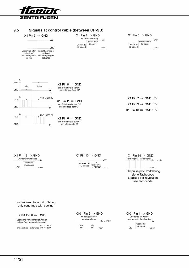
9.5 Signals at control cable (between CP-SB)
+UB
GNDDeckel zulid closed
Deckel offenlid open
X1 Pin 4 GNDFC Hardware Stop
+5V
GNDDeckel zulid closed
Deckel offenlid open
X1 Pin 5 GND
X1 Pin 7 GND : 0V
X1 Pin 9 GND : 0V
X1 Pin 10 GND : 0V
+5V
GNDOK
Unwuchtimbalance
X1 Pin 12 GNDUnwucht / Imbalance
+5V
GND
X1 Pin 13 GND
FC-ERRORFC-Fehler
OKkein Fehlerno ERROR
+8V ... +15V
GND
X101 Pin 2 GND
ausoff
einon
Kühlung aus / eincooling off / on
+5V
GNDOK
Übertemp.overtemp.
X101 Pin 4 GNDÜbertemp. im Kessel
overtemp. in the chamber
+UB
GNDVerschluß offen
oder Lauflid locking open
or run
Verschlußmagnetaktiviert
lid locking magnetactivated
X1 Pin 3 GND
+8V ... +15V
GND
Tachosignal / tacho signalX1 Pin 14 GND
6 Impulse pro Umdrehung
6 pulses per revolutionsee tachocode
siehe Tachocode
X101 Pin 8 GNDSpannung vom Temperaturfühlervoltage from temperature sensor
25°C = 2.98VUnterschied / difference 1°K = 10mV
nur bei Zentrifuge mit Kühlungonly centrifuge with cooling
X1 Pin 6 GNDser. Schnittstelle zum CP
ser. interface to CP
+5V
GNDt
RxD (4800 B)
X1 Pin 11 GNDser. Schnittstelle vom CP
ser. interface from CP
TxD (4800 B)+5V
GNDt
X1 Pin 8 GNDser. Schnittstelle vom CP
ser. interface from CP
+5V
GND
talk
t
listen

45/51
9.6 Block diagram control panel (CP)
+Ub
23
45
67
89
1011
1214
1315
161
zur V
erso
rgun
gspl
atin
e (S
B)
A1 /
X2
to s
uppl
y bo
ard
(SB
) A1
/ X2
X1
GND&
&EE
PRO
M
EPR
OM
Steuerteil A4control panel A4
+5V
+5V
+5V
Tast
atur
/ ke
yboa
rdLC
D -
Dis
play
LED
- A
nzei
geLE
D in
dica
tors
µP
U (5.00V)r e f
Reset
Verschluss / lid locking
FC Stop
Deckel offen / lid open
RxD
empfangen / sendenlisten / talk
TxD
Unwucht / imbalance
FC - ERROR
Tacho in
Temp.-fühlertemp. sensor
Kühlung aus / eincooling off / on
Übertemp.-erkennungovertemp. detection
23
45
67
89
101
zur K
ühlu
ngsp
latin
e(C
B) A
3 / X
4(n
ur g
eküh
lte V
ersi
on)
to c
oolin
g bo
ard
(CB)
A3
/ X4
(onl
y re
frige
rate
d ve
rsio
n)
+Ub
GND
X101
24
1
X100

46/51
9.7 Connecting diagram Control board (CP)
41
11
1610
43210
zur Kühlungspaltinenur gekühlte Version
to cooling boardonly refigerated Version
zur Versorgungsplatineto supply board
Steuerteil A4control panel A4
A4/X101 A4/X1
A3/X4 A1/X2
110
116
1110 16
X3
X101 X1
X10
0

47/51
9.8 Block diagram and control panel signals at FC
UU
DC
+5V
GND
Pin 3 = A GND+5V
GND
Pin 5 = B GND
+5V
GND
FC- FehlerFC- ERROR kein Fehler
no ERROR
Pin 4 GND+5V
GND
Deckel zuLid closed Deckel offen
Lid open
Pin 7 GNDFC Hardware Stop
+8V ... +15V
GND
Tachosignal / tacho signalPin 8 GND
Signale an S501:signals at S501:
Übertemperaturschalter F3 für R1overtemperature switch F3 for R1
F3>
>
1 2
L1
Netzdrossel L1mains choke coil L1

48/51
9.9 Connecting diagram frequency converter (FC)
W2
V2
U2
S101
Bremswiderstandbrake resistor
S501S2
P10 ++
-
P1-
S10
2
UUDC BU
BN
BKN
U1
PE
UUAC
U = Netzspannung / mains voltage
AC
U = U x 2DC ACA2 Frequenzumrichter/
frequency converter
M13
Motor / motor
R1
Übertemperaturschalter für R1overtemperature switch for R1
F3
vom Funkentstörfilter Z1/4 from radio interferencesuppression filter Z1/4
vom Funkentstörfilter Z1/3 from radio interferencesuppression filter Z1/3
Netzdrossel L1(nur bei ROTINA 35, 230 V Ausführung;
)mains choke coil L1(only with ROTINA 35, 230 V model;from serial no. XXXX-06-00)
ab Werk Nr. XXXX-06-00
zur Versorgungsplatine A1 / X9to supply board A1 / X9
S501
12
S2
>
1 2
L1
Bremswiderstand 230 V Ausführung: 160 Ω Brake resistor 115 V Version: 70 Ω Motorwiderstand (kalter Motor, zwischen je 2 Leitungen) Motor resistance value (cold motor, between 2 wires) 230 V Ausführung: 4,3 Ω 115 V Version: 0.7 Ω

49/51
9.10 Circuit diagram cooling board
1 2 4 5 6
1 2 3 4 5 6
1 2 4 5 6
C5
100n
F
100n
F
100
F/35
V
C2
C3
21 3 4 5 6 7 8 9 10
X4
R2
R4
R3
1k7
2k2
10kD1
1N4148
C4 100n
F
C6
100n
F
12
12
GN (YE)
BN (GN)
WH (BN)
YE (GY)
YE
YE
X3X2
D2
1N41
48
RE
L1R
P33
0012 C6
100n
F
+Ub
T1BC327
21 3 4 5 6X1
654321
R1
VDR1
220n
F/25
0VC1
10R
/250
V
M4
M3
BK WH
Küh
lung
plat
ine
A3
cool
ing
boar
d A
3
B2B
1
WH
WH
BK
BK
+Ub
X8X7
von
Vers
orgu
ngsp
latin
e A1
from
sup
ply
boar
d A
1
2 3 4 5 6 7 8 9 101
zum Steuerteil A4 / X101to control panel A4 / X101
1011
1213
14
Anla
uf-
kond
ensa
tor
star
tup
cond
ense
r
Wic
klun
gssc
hutz
scha
lter
win
ding
pro
tect
ion
switc
hM
2
vom
Fun
kent
stör
filte
r Z1
(230
V
)vo
n Kl
emm
e X
10 (1
15 V
)
from
radi
o in
fere
nce
supp
ress
ion
filte
r Z1
(230
V m
odel
)fro
m te
rmin
al s
trip
X10
(115
V m
odel
)
Aus
führ
ung
Aus
führ
ung
Z1 /
2X
10Z1
/ 1
X10

50/51
9.11 Connecting diagram and component layout cooling board
BNWH
GN YE
1 2 3 4 5 6
Temperaturfühler und Über-temperaturschalter im Kessel
temperature sensor and overtemperature switch in centrifuge chamber
B1
1 2
Übe
rtem
pera
turs
chal
ter i
m K
ühls
yste
mov
erte
mpe
ratu
re s
witc
h in
coo
ling
syst
em
WH
or G
N o
r GY
BN
or Y
E o
r PK
6
2 3
5
14
vom
Fun
kent
stör
filte
r Z1
(230
V
)vo
n K
lem
me
X10
(115
V
)fro
m ra
dio
infe
renc
e su
ppre
ssio
n fil
ter Z
1 (2
30 V
mod
el)
from
ter
min
al s
trip
X10
(115
V m
odel
)
Aus
führ
ung
Aus
führ
ung
zur Versorgungsplatine A1to supply board A1
zum Steuerteil A4to control panel A4
A4 / X101
A3 / X4
X8X7
X3
WH
BK
Z1 /
1X1
0Z1
/ 2
X10
X1
BK WH
14 5 6
2 3 C1
VDR1
R1
C6 C4 C5
X1
C3
X4
R2R3R4D1
C2
+1
1
C7
T1
REL
1
D2
1
10 11
12 1314
Anlauf-kondensator
startup condenser
Wicklungsschutzschalterwinding protection switch
M2
B2
M4 M3
BKWH

51/51
10. Technical specifications
Manufacturer
Hettich Zentrifugen D-78532 Tuttlingen
Model ROTINA 35 ROTINA 35 R Product no. 1705 1705-01 1710,
1710-20 1710-01
Mains voltage (± 10%) 220-240 V 1∼ 110-127 V 1∼ 208-240 V 1∼ 110-127 V 1∼Mains frequency 50-60 Hz 50-60 Hz 50 Hz 60 Hz Connected load 880 VA 760 VA 1300 VA 1500 VA Current consumption 4.2 A 7.8 A 6.5 A 13.5 A Power consumption 600 W 620 W 1100 W 1200 W Refrigerant ----- R 404A Max. capacity 52 x 15 ml Max. density 1.2 kg/dm3 Speed RPM 15000 Force RCF 23 646 Kinetic energy 18500 Nm 22000 Nm Obligatory inspection yes Environment − Ambient temperature 5°C up to 40°C − Relative humidity max. 80% up to 31°C,
descending in a linear pattern down to 50% at 40°C
Sample overtemp. ≤ 15 K ----- Class of protection Ι EMC ISM (Industrial Science Medicine) − Emission
(Radio interference suppression)
EN 55011 Class B
FCC Class B
EN 55011 Class B
FCC Class B
− Immunity according to EN 50082-2 Noise level (dependent on rotor) 52 bis 66 dB(A) 46 bis 66 dB(A)
Dimensions • Width 468 mm 468 mm • Depth 540 mm 695 mm • Height 380 mm 380 mm Weight approx. 43,1 kg 70 kg