re~ort bv martin liddament. head of air infiltration and
TRANSCRIPT

International Energy Agency - AlVC Vol. 18, No.4, September 1997
Re~or t bv Martin W. Liddament. Head of Air Infiltration and Ventilation Centre
The impact of urban particulate pollution on indoor air quality is becoming a growing concern, with new re- search highlighting the risks to building occupants. Results show that such contaminants can be detri- mental to human health and comfort and are an im- portant factor in maintaining acceptable indoor air quality. Current information and research was re- viewed at a Seminar.
William Wilson of the United States Environmental Protection Agency presented an overview of particu- late contamination and its impact on health. He also reported that new proposed standards were shortly to be published covering particulate concentrations. Early evidence was taken from the London (England) smogs of 1962, which showed a distinct correlation between periods of smog and subsequent peaks in
@ death rate. Since then much more detailed studies . have revealed similar correlations between particu-
late intensity and increased incidences of death.
The significance of particle size on health was stressed. Essentially, particles vary in size from frac- tions of a micron (ym) up to clearly visible material of 100pm or more. Two size ranges have been intro-
duced, in part reflecting the severity of impact on hu- mans. These ranges are:
'fine mode' particle range (i.e. particle sizes up to 2.5ym); 'course mode particle range (i.e. greater than 2.5ym).
Fine mode particles penetrate the deepest levels of the lung (thoracic region). They are difficult for the body to expel and are thought to cause most dam- age. Hitherto, much reseaah and many standards have been based on 'PMio's', 'respirable' particles of size up penetrate the lung). These show strong correlation with health but more recent research suggest that it is the 'PM2.5' (i.e. up to 2.5pm) component that has the greatest adverse health effect. Existing research, including that of tQe 'Harvard Six City Study' shows that each 10yglm of PMio results in a measurable increment in death rate (present standards for PMqo's are set at 50yglm3).
A study in Riverside, California, has focused on the sources of particulates in the home (Figure 1). This shows that approximately 76% of PM2.53 are derived from the outside air whereas the figure for PMio's is 66%. 'Other' indoor sources include insect frag- ments, especially in the PMlo range. The ambient in-
In this issue
.......................... New Products - MSP Cleanroom FoggerTM and Portable Cleanroom FoggerTM Page 5
AlVC Website Update .................................................................................................................... Page 6
Passive Sfack Ventilation with Heat Recovery ............................................................................... Page 7
Publications Catalogue ................................................................................................................. age I I
Forthcoming Conferences. ...................................................................................................... page 15
Air In.ltration Review, Vol18, No 4, September 1997 1

door to outdoor ratio is shown to depend on the air change and deposition rates. More PM2.5 gets into the building than PMlo. At about 2 air changeslhour PM2.5 concentrations approaches about three quar- ters or more of the outdoor value.
sure to fine particulate matter. By using personal ex- posure monitors and observing the movements of vol- unteers, she is assessing the contributing sources of particles to individuais. Personal exposure (X) is evaluated from:
Sources of Indoor Particles (Based on 178 homes in the US. Wilson EPAI
where xi = exposure over time ti
--
outdoor a smoking cooking !E4 other sources
Following this presentation, Eileen Abt of the Harvard School of Public Health in Boston talked about an on- going study on the characterisation of particulate sources in four urban (non-smoking) homes. Cur- rently, monitoring of the indoor environment has taken place in each home, for 6 day periods in Winter and Spring. Measurements have included:
o particles 0.02-1 Opm, PM2.5 and PMio (continuous and integrated, indoor and outdoor) particles PM2.5 and PMio air change rate (SF6 Tracer Gas) temperature relative humidity wind speed and direction
An initial analysis of diurnal results shows that in the early morning (3 a.m.), the indoor and outdoor con- centration of particles is similar. During the day, the indoor concentration becomes influenced by house- hold activities, especially cooking (by gas) and vac- uum cleaning.
Barbara Turpin of Rutgers Cook College described her current research into monitoring personal expo-
Results show that between 50-80% of inhaled fine particles are from outdoor sources.
Also while the average exposure to PMio's to a com- munity depends on the ambient pollution, individual exposure is highly variable, depending very much on the micro climate and the individuais' activities. Bar- bara Turpin further expressed a need to chemically characterise individual exposure, for example to spe- cific pollutants such as:
o metals (chromium, cadmium, lead, arsenic, vanadium) hydrocarbons
a o other materials including sulphates, ammonium
compounds, Teflon, silicates, amides.
She stressed that the techniques being developed in this study would have important applications in future pollutant health effect and personnel monitoring stud- ies.
David Pui of the University of Minnesota went on to characterise oarticulate'sdurces based on indoor and outdoor measurements. Ty cluded organic carbon, sulp coarse materials included soil, minerals, nitrates and road dust.
ew Research Topics
Various new ASHRAE research topics have been proposed. Those for which outline Work Statements have been prepared include:
Editor: Janet Blacknell
Air lnfilfration Review has a quarterly circulation of 3,500 copies and is currently distributed to organisations in 40 countries. Short articles or correspondence of a general technical nature related to the subject of air infiltration and ventilation are welcome for possible inclusion in AIR. Articles intended for publication must be written in English and should not exceed 1,500 words in lenath. If vou wish to contribute to AIR, please contact the Air lnfiitration and Ventilation Centre. Please note fhat all submitted papers should use SI units.
Air InJitration Review, Yo1 18, No 4, September I997

Integrating Current AS RAE Results on Air Flow Around Buildings into Practical Design Guide- lines
Air flow around buildings has many important implica- tions, for example in terms of pollutant transport, air infiltration, and natural ventilation design. An update was covered by a seminar on what designers need to account for. Currently, many design procedures for incorporating knowledge about outdoor air flow are in- adequate. To address this a proposal has been pre- pared aimed at the translation of research results and existing knowledge into practical calculation tech- niques that can be used by building designers. The intention is to:
summarise current (ASHRAE) research; produce updated simplified design tools; identify areas of building air flow requiring further research.
Exhaust Contamination of Hidden Vs. Visible Air Intakes
It has become common for designers to place air in- @ takes on the walls of buildings, just below the roof,
rather than on the roof itself. One of the aims is to 'hide' the intake from roof level exhausts. Although there is a perception, among designers, that inlet air is likely to be less contaminated, more systematic in- formation is needed. The intention of this project is to:
analyse the characteristics of 'diluted' plumes; determine the performance of a 'hidden' intake in relation to a roof exhaust and an identical exhaust on an adjacent wall; evaluate the significance of the building shape and size.
Heat Transfer During Residential infiltration and Exfiltration
The purpose of this proposal is to evaluate the im- pact of thermal coupling between infiltrating air and in- sulating layers (i.e. assessing the impact of any infiltration 'heat recovery' under normal conditions of @ air infiltration). The objective is to measure the en- ergy impact of infiltrationlexfiltration in real yet typical dwelling units. A reliable technique needs to be devel- oped for measuring the heat transfer between infiltrat- ing and exfiltrating air and conduction heat flows through residential building envelopes. Based on the experimental results, the impact of air infiltration on load calculations will be provided.
Simplified Models for Room Air and Air Contami- nant Distribution
Understanding the air and air contaminant in rooms is important for the design and operation of room air distribution systems. While computational fluid dy- namic models provide comprehensive detail they are generally too complicated to be used directly for de- sign. This seminar reviewed simplified models for pre- dicting air flow. Per Heiselberg of Aalborg university, Denmark considered air movement in terms of indi-
vidual flow elements. These included:
air jets described by semi empirical equations based on laboratory measurements;
o plumes above heat sources;
In 'normal' size enclosures flow throughout the space is dominated by each flow element. In 'large' enclo- sures flow elements tend only to affect flow locally. Examples were illustrated in which elements could be treated as non-interacting (e.g. displacement flow) and in which simple zonal models could be used to combine flow elements.
Qingyan Chen of MIT described a simplified zero equation turbulence model, based on a 'local' mixing length. Computational time was reduced to 111 00th of that needed for a conventional k-E approach. This resulted in a typical three dimensional CFD problem being solved within 10 minutes on a PC with a mini- mum loss of performance.
Alexander Zhivov of the University of Illinois de- scribed the use of multi-zone heat and mass balance equations for practical applications while John Shaw of the NRC in Canada presented a review of simpli- fied models.
Seminar on Sensory Panels and the Assessment of Indoor Air Quality
Developments in odour perception were reviewed by Ole Fanger (Technical University, Denmark), James Woods (Virginia Tech, USA), Jarrel Wenger (Johnson Controls, USA) and Diotimi von Kempski (DVK, Germany). Discussion covered the need for sensory panels, the significance of odour as a pollut- ant and the difficulties assoc with defining the perception of comfort. Jarrel ger described pro- gress with an 'electronic' nose which was tested against a 'trained panel'. Various complexities of sen- sory arrays were used covering the simultaneous measurement of common gases and vapours, par- ticulates, VOC's, humidity, noise, light intensity, tem- perature, radiation, air velocity and turbulence. In many instances, panel judgements were found to be concurrent with sensor readings but, in price, the equipment was prohibitively expensive. The best sin- gle instrument was found to be an infra-red detector optimised for methyl methacrylate. Correlation be- tween carbon dioxide concentration and the sensory panel was found not to be good. A reduced 'optimal' set of eleven sensors was found to be a fairly reliable indicator of odour and it was thought that this could be further reduced to seven sensors.
Air related Technical Sessions and Symposia for which papers are published, (and referenced in AIR- BASE) included:
demand controlled ventilation and IAQ; fire in atria and other large spaces;
Air InJiltration Review, Vol18, No 4, September 1997

IAQ control strategies and Con monitoring (poster session).
Developments to AS Standard 62 - Call for Members
There is still much on-going activity continuing with the updating of Standard 62 on Ventilation for Ac- ceptable lndoor Air Quality. Sessions included fo- rums entitled 'should ASHRAE Standards relevant to IAQ be based on health or comfort', 'ASHRAE's role in IAQ' and ASHRAE Standard 62 compliance: cen- tral vs local ventilation control.
The Standards Committee approved separating the proposed revision of ANSIIASHRAE standard 62- 1989 Ventilation for Acceptable lndoor Air Quality into two separate proposed standards. SSPC 62 was redesignated as SSPC 62.1 with the charge of revising portions of Standard 62-1989 that relate to all buildings except low-rise residential buildings. The Standards Committee authorised a new project committee, SPC 62.2P, to revise portions of Stand- ard 62-1 989 that relate to low-rise residential build- ings. A call for members is announced for this project committee as described below. Experts who are interested in serving on SPC 62.2P are asked to indicate their interest and obtain the necessary forms from the Manager of Standards, ASH RAE, 1791 Tul- lie Circle N.E., Atlanta, GA 30329-2305.
SPC 62.2P
Ventilation and Acceptable lndoor Air Quality in Low-Rise Residential
Buildings
1 Purpose.
This standard defines the roles of and minimum re- quirements for mechanical and natural ventilation sys- tems and the building envelope intended to provide acceptable indoor air quality in low-rise residential buildings.
2 Scope
2.1 This standard applies to spaces intended for hu- man occupancy within single-family houses and multi- family structures of three stories or fewer above grade, including manufactured and modular houses. This standard does not apply to transient housing such as hotels, motels, nursing homes, dormitories or jails.
2.2 This standard applies to new buildings, additions to existing buildings, and some changes to existing buildings.
2.3 This standard considers chemical, physical and biological contaminants that can affect air quality. Thermal comfort requirements are not included in this standard (see ASHRAE Standard 55).
2.4 While acceptable indoor air quality is the goal of this standard, it will not necessarily be achieved even if all requirements are met:
a) because of the diversity of sources and contami- nants in indoor air and the range of susceptibility in the population;
b) because of the many other factors that may af- fect occupant perception and acceptance of indoor air quality, such as air temperature, humidity, noise, lighting and psychological stress;
c) if the ambient air is unacceptable and this air is brought into the building without first being cleaned. (Cleaning of ambient outdoor air is not required by this standard.); or
d) if the system(s) are not operated and maintained as designed.
E Symposium "Ventilation in Light Commercial Buildings" -
Call for Papers I
It is proposed to hold a symposium on ventilation in light commercial buildings at the Chicago ASHRAE Meeting in January 1999.
The purpose of this symposium is to focus on recent activities covering air change rate, airtightness and air quality relating to such buildings. Building types in- clude:
w shopping malls and retail outlets warehouses - .
w small factory units w other similar structurea-
Abstracts of papers are required now and should be sent to Martin Liddament at the AIVC.
Don Colliver - Former AIVC Visiting Specialist becomes ASHRAE Vice
President
Professor Don Colliver, visiting specialist to the AIVC in 1995 was elected as a Vice President to ASHRAE. During his time at the AIVC Don undertook work on the effect of climate on the, energy impact of ventila- tion. This work (documented in AIVC Technical Note 47) involved the analysis of long-term hourly weather data from a number of European and American loca- tions. The intent was to determine the psychrometric process theoretical heating, cooling and moisture re- moval energy requirements for a constant mass of airflow per hour. This was performed for a range of temperature and humidity setpoints.
For further Information:
For further information about any of these ASHRAE activities, please contact Martin Liddament at the AIVC
Air InJitration Review, Vol18, No 4, September 1997
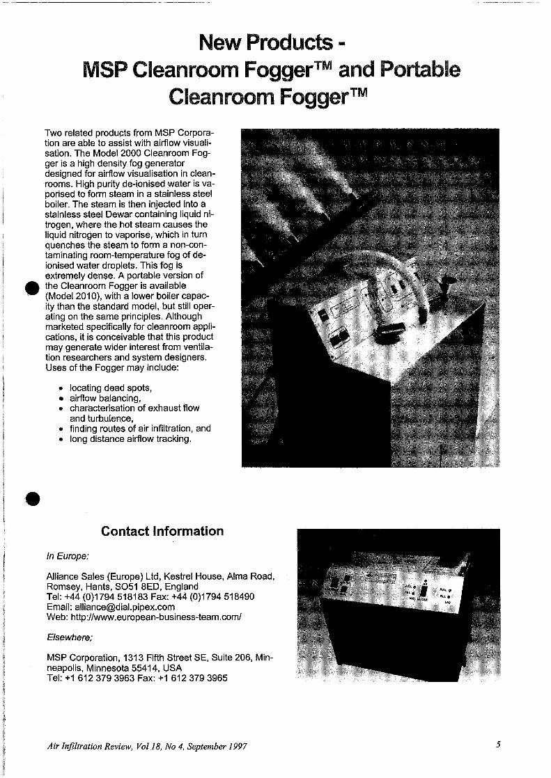
Two related products from MSP Corpora- tion are able to assist with airflow visuali- sation. The Model 2000 Cleanroom Fog- ger is a high density fog generator designed for airflow visualisation in clean- rooms. High purity de-ionised water is va- porised to form steam in a stainless steel boiler. The steam is then injected into a stainless steel Dewar containing liquid ni- trogen, where the hot steam causes the liquid nitrogen to vaporise, which in turn quenches the steam to form a non-con- taminating room-temperature fog of de- ionised water droplets. This fog is extremely dense. A portable version of the Cleanroom Fogger is available
@ (Model 201 0). with a lower boiler capac- ity than the standard model, but still oper- ating on the same principles. Although marketed specifically for cleanroom appli- cations, it is conceivable that this product may generate wider interest from ventila- tion researchers and system designers. Uses of the Fogger may include:
e locating dead spots, airflow balancing,
e characterisation of exhaust flow and turbulence, finding routes of air infiltration, and
e long distance airflow tracking.
@
In Europe:
Alliance Sales (Europe) Ltd, Kestrel House, Alma Road, Romsey, Hants, SO51 8ED, England Tel: +44 (0)1794 51 81 83 Fax: +44 (0)1794 51 8490 Email: [email protected] Web: http:llwww.european-business-team.com/
Else where:
MSP Corporation, 131 3 Fifth Street SE, Suite 206, Min- neapolis, Minnesota 5541 4, USA Tel: + I 612 379 3963 Fax: + I 612 379 3965
Air Infitration Review, Vol18, No 4, September 1997

This summer has seen a dramatic transformation of the AIVC's World Wide Web site, thanks to the efforts of Juliet Owen, a Design Studies student from Nottingham Trent University in the UK. She has spent eight weeks at the Centre this summer applying her artistic and design skills to the existing Web site, as part of a student project. As a result, the site has been improved considerably in its layout and design. In particular, 'frames' have been added, to allow easier navigation around the site, whilst still retaining a 'no-frames' option for users without frames-enabled Web browsers. (For those considering upgrading to frames-enabled browsers, exam- ples include Netscape Navigator, obtainable from http://ww.netscape.com/and Microsoft Internet Explorer, which can be found at http://www.microsoff.com/.) Navigation buttons have been added in fixed toolbars to make it easier to find Danes. Another maior addition to the Web site, also desianed bv Juliet, is an on-line or- der form for all AlVC pub~ications.
-
The inch
The AlVC staff would like to thank Juliet for her hard work and wish her every success in her future studies.
Please visit us at http://www. aivc. org/.
Air InJiltration Review, Vol18, No 4, September 1997

by S B Riffat and G Gan
Institute of Building Technology, Department of Architecture and Building Technology, University of Noffingham, UK
Ventilation accounts for 30% or more of space condi- tioning energy demand but as much as 70% of this energy can be recovered by the use of ventilation heat recovery systems [I]. Until now, effort has mainly been devoted to the design and development of heat recovery systems for mechanically-ventilated buildings. However, most domestic buildings are naturally ventilated and little consideration has been given to heat recovery from these buildings. A crucial parameter limiting the use of heat recovery with natu- ral ventilation is pressure loss. The total pressure loss through a natural ventilation system so that suffi- cient air pipes would have the potential to provide substantial heat recovery without significant pressure loss.
A heat-pipe heat recovery unit is a heat exchanger consisting of externally-finned sealed pipes using a working fluid such as methanol or water. The unit is divided into two sections, i.e., the evaporator and the condenser, for heat exchange between exhaust and supply air (see Figure 1). In addition to low flow resis- tance, a heat-pipe heat exchanger has a number of other advantages over conventional heat exchangers such as high reliability, no cross-contamination, com- pactness and suitability for both heating and cooling.
were determined by computational fluid dynamics (CFD).
Four types of heat-pipe heat recovery units were con- structed and tested. Figure 2 shows the cross-sec- tion of the heat pies. The working fluid in the pipes was methanol with an operating temperature range from -40°C to 100" C.
Type I (plain fins) - x Type II (spine fins)
@ Cold outdoor air Exhaust air
Type JII Oouvred fins) Type N (wire fins)
Figure 2: Cross-section of heat pipes.
Figure 1: Schematic diagram of heat-pipe heat recovery.
The objective of this work is to assess the perform- ance of heat-pipe heat recovery units for naturally- ventilated buildings. The effectiveness of four heat-pipe units was measured in a two-zone cham- ber. The pressure loss characteristics of the units
The first heat recovery unit (Type I) consisted of a bank of seven externally finned heat pipes. Each pipe was 0.0127 m in outside diameter and 0.45 m in length with 72 continuous plain fins (0.21 5 m long, 0.048 m high and 0.45 mm thick) on both the con- denser and evaporator sections. The cross-sectional area of both the consender and evaporator sections was 0.21 5 x 0.21 5 m. The total surface area of each finned pi e including fins and exposed pipe was P 0.196 m . The whole unit was made of copper.
Air Infitration Review, Vol18, No 4, September I997

The second type heat pipe had cylindrical spine fins. The fins were made of copper wire. The unit with this type of fin consisted of three heat pipes of the same size and material as for Type I. There were eight con- tinuous rows of fins on each of these pipes. Each row had about 300 spine fins and each spine fin was 0.7 mm in diameter and 30 mm long. The estimated total surface rea of the spine fins of each heat pipe was 3 0.1 58 m , which is about 19% less than that of the continuous plain fins.
The third type of heat recovery unit was made of two rows of staggered heat pipes. Each row consisted of three heat pipes. Each pipe was 18 mm in diameter and 365 mm in length with 70 continuous louvred alu- minium fins on both the condenser and evaporator sections. Each fin was I80 mm long and 60 mm high and had 96 louvres with 2 mm spacing and 0.65 mm gap. The cross-sectional areas of the condenser and evaporator sections were 180 x 180 mm and 175 x 180 mm, respectively. The total surface area for heat transfer to the evaporator section was 1.541 8 m2; this is about 8% more than that for Type I heat pipes.
The fourth type of heat recovery unit was made of five in-line heat pipes with wire fins. Each pipe was 19.05 mm in diameter and 450 mm long with 34.5 turns of copper wire fins on both the condenser and evaporator sections. Each turn of fins had 65 loops of wire 0.65 mm in diameter and 12 mm high. The cross-sectional area of the unit is the same as that of the first type of heat pipe. The total surface area for heat transfer of the evaporator or condenser section was 0.6035 m2; this is less than half of the first type.
ffectiveness of Heat Recovery
The effectiveness of a heat-pipe heat recovery unit for sensible heat exchange between supply and ex- haust air of the same flow rate,& (%), is defined as:
where Ti and Ts are the temperatures of inlet air be- fore and supply air after the condenser section of heat exchanger in the supply duct (" C) respectively, and Tr is the temperature of return air before the evaporator section of heat exchanger in the exhaust duct ("C) (see Figure 1).
Measurements of the effectiveness were carried out in a vertical two-zone test chamber with a heat-pipe heat recovery unit [2]. The two-zone test chamber was designed to allow good mixing of supply air with room air in the lower zone and maintain a uniform temperature and concentration of return air in the up- per zone and so to ensure the reliability of tempera- ture and air flow measurements. Thermocouples were used to measure temperatures. The air flow rate was measured using the constant-injection tracer-gas method.
Figure 3 shows a comparison of the measured effec- tiveness for the four types of heat pipes. It can be seen that the rate of heat recovery increases with de- creasing air velocity. However, for a given heat recov- ery unit this does not necessarily increase the total amount of heat recovery (proportional to velocity).
0 2 4 6 8 1 0
Mean air velocity (m/s)
Figure 3: Comparison of effectiveness for four types of heat pipes.
The effectiveness for the spine-fin heat pipes pre- sented in Figure 3 was for seven equivalent heat pipes. The effectiveness for this type of heat recov- ery unit was much lower than that of plain-fin heat pipes. The main reason for the ineffectiveness of spine-fin heat pipes is the poor thermal contact be- tween fins and pipes, resulting in a high contact resis- tance.
For the same cross-sectional area, the staggered heat pipes with louvred fins were more effective than plain fins, particularly at lower velocities. This may be attributed mainly to the increa d external surface area available for heat transfer per unit cross section (55% more).
The effectiveness of the unit with wire fins was lower than that with plain fins. This is due to the lower exter- nal surface area for the wire-fin heat pipes. If the sur- face area was increased by say 50%, which would still be less than that of the plain-fin heat pipes, the ef- @I fectiveness would be higher than that of the plain-fin heat pipe unit.
The effectiveness of heat pipes could be increased by employing more than one bank. For example, for Type I heat pipes, the measured heat recovery was between 16% and 17% more efficient using two banks than using one bank. Employing multiple banks of heat pipes would however increase flow re- sistance and cost of installation. For natural ventila- tion the resulting pressure loss must be smaller than the driving force so that adequate air flow rates can still be achieved.
ressure Loss Across
The pressure loss across a heat-pipe unit is repre- sented by the pressure loss coefficient (k) as follows:
Air Infiltration Review, Vol18, No 4, September 1997

where A Ps is the static pressure loss across the unit (Pa), V is the mean velocity of air flowin over the 9 unit (rnls) and p is the air density (kglm ).
The pressure loss coefficient for Type I and Ill heat- pipe units was predicted by means of CFD modelling. The predictions were carried out using the CFD pack- age FLUENT [3]. In the predictions, each row of heat pipes was modelled as one bank of rectangular cylin- ders such that it had the same free-area ratio and thickness as the real heat pipes. The fins were mod- elled as uniformly distributed rectangular studs on both sides of heat pipes such that the total cross-sec- tional area of the studs was the same as the sum of that of the fins.
The pressure loss coefficient was found to decrease with increasing mean air velocity. The pressure loss coefficient for Type I heat pipes can be correlated to velocity between 0.25 and 10 rnls as follows:
where n is the number of heat-pipe banks.
The pressure loss at a given velocity can be obt~ined from the pressure loss coefficient (= 1 / 2kpV ). For example, at a velocity of 0.5 mls, the pressure loss through a section of one bank of heat pipes is about 0.57 Pa and total pressure loss through the whole unit (both condenser and evaporator sections) is just over 1 Pa. Thus, if the driving pressure avail- able for ventilation is, say, 1 Pa, the mean velocity through the heat-pipe unit should not be more than 0.5 rnls. At a velocity of 1 mls, the pressure loss through both sections of the unit is 4.5 Pa. Without the wind effect, this would require a stack height of about 10 m at a temperature difference between inlet and exhaust openings of 10 K, or 4 m height at 25 K temperature difference. In naturally-ventilated low- rise buildings, the average driving pressures are un- likely to exceed this value. Therefore, in designing ventilation ducts for housing this type of heat recov- ery unit, the mean air velocity should be less than 1 mls.
Figure 4 shows a comparison of pressure loss coeffi- cient for Type I and Type Ill heat pipes. The pre- dicted loss coefficient for the six staggered 18 mm heat pipes was higher than that for one bank of seven heat pipes of 12.7 mm in diameter despite the porosity (free-area ratio) of the former being higher than that of the latter. When the six pipes were ar- ranged as a two-row in-line bank, the predicted loss
coefficient became lower than that of one bank of seven smaller heat pipes. For example, at a velocity 1 mls, the predicted loss coefficient for the two-row in- line six pipes was 3.3, compared with 4.2 for the stag- gered pipes and 3.7 for the in-line seven smaller heat pipes.
4 0 1 2 3 4 5 6
Air elocity ( d s ) Figure 4: Effect of pipe arrangement on the pressure loss coefficient.
It is shown that air velocity has a significant effect on the effectiveness of heat-pipe heat recovery. The ef- fectiveness decreases with increasing air velocity. For heat pipes with plain fins, at the same velocity the heat recovery is between 16% and 17% more effi- cient using two banks than using one bank. Poor ther- mal contact between fins and pipes can drastically reduce the effectiveness of heat pipes.
. * At low velocities the pressure loss coefficient de- creases with increasing air v tocity but the total pres- sure loss still increases with the velocity. It is recommended that in naturally-ventilated low-rise building, without the wind effect or solar energy, the design mean air velocity should be less than 1 rnls in order for a heat recovery system to function properly.
This project is funded in part by the Commission of European Union under the "JOULE Ill" Programme.
1. Liddament M W, "A Guide to Energy Efficient Ventilation", AIVC, Coventry, UK, 1996.
2. Riffat S B and Gan G, "Determination of effectiveness of heat-pipe heat recovery for naturally-ventilated buildings", Applied Thermal Engineering (in press).
3. FLUENT User's Guide, Fluent Inc. USA, 1993.
Air Infiltration Review, Vol18, No 4, September 1997

In ion e .
Preliminary Announcement
Air distribution in buildings is generally carried out by ducted systems. To achieve a good performance, various requirements have to be met, including, among others, low friction losses, durability, clean systems, and effective airtightness. Over the last few years closer attention has been paid to the performance of these
various aspects.
The international seminar on 10 and 11 June 1998 in Brussels will focus mainly on the aspect of airtightness. Airtightness classes for ductwork have been developed by EUROVENT for many years and several countries
have airtightness requirements for ducted air distribution systems. But what is the status in practice? What improvements are possible in the future? What is the impact of poor airtightness on system performances:
indoor air quality, energy use, etc.? Is it technically possible and useful to increase the requirements? What is the status at CEN level?
It can be seen from the preliminary programme that all key aspects of the issue will be discussed:
Ductwork in the overall context of ventilation, Preliminary outcome of the survey among IAQ and energy manufacturers and installers
o Overview of standards and regulations Results of field measurements in the SAVE-DUCT project
Activities in the context of CEN TC 156 WG3 "Ductwork" Progress in duct design of the last 25 years
o Overview of practices in various countries Economic aspects of improved airtightness
and more ...
Leading experts in the field have been contacted to give presentations, and more presentations are planned.
Those interested in contributing or receiving more information should contact P Wo (telephone +32 2 655 77 11, Fax +32 2 653 07 29 or email [email protected])
The initiative for setting up this seminar is taken in the framework of the EC programme SAVE (Specific Actions for Vigorous Energy efficiency measures).
ew Technical
Ventilation Technology in Large Non-Domestic Buildings, by Don Dickson
Energy Impact of Ventilation - Estimates for the Service and Residential Building Sectors, by Malcolm Orme
Air InJiltration Review, Vol18, No 4, September 1997

JOURNALS *Air Infiltration Review. Quarterly newsletter containing topical and informative articles on air infltration research and application. Annual subscription £25.00 "Recent Additions to AIRBASE. Quarterly bulletin of abstracts added to AIRBASE, AIVC's bibliographic database.
AIRBASE The AIVC's bibliographical database, containing over 10,000 records on air infiltration, ventilation and related areas, is available on CD or as a diskette package for your personal computer. AIRBASE £ 150.00 plus VAT where applicable
WORLD WIDE WEB The AIVC's home page holds Air Infiltration Review, publications and conference details and a list of papers based on the current edition of Recent Additions. The address is http://www.aivc.org/
GUIDES Guide to Energy Efficient Ventilation, Liddament M W, 1996 GV £50.00 Air Infiltration Calculation Techniques: an Applications Guide, 1986, CT £15.00 Air infiltration control in housing: Handbook, 1983 HNBK £15.00
TECHNICAL NOTES Validation and comparison of mathematical models, 1983 TN 11 £15.00 Wind pressure data requirements, 1984, TN 13 £15.00 Wind Pressure Workshop Proceedings, 1984, TN 13.1 £15.00 Leakage Distribution in Buildings, 1985, TN 16 £15.00 Ventilation Strategy - A Selected Bibliography, 1985, TN 17 £ 15.00
Airborne moisture transfer: workshop proceedings, 1987, TN 20 £15.00 Review and bibliography of ventilation effectiveness, 1987, TN 21 £15.00 Inhabitants' behaviour with regard to ventilation, 1988, TN 23 £15.00 AIVC Measurement Techniques Workshop, 1988, TN 24 £15.00 Minimum ventilation rates, IEA Annex IX 1989, TN 26 £15.00 Infiltration and leakage paths in single family houses, 1990, TN 27 £15.00 A guide to air change efficiency, 1990, TN 28 £15.00 A guide to contaminant removal effectiveness, 199 1,
A Strategy for Future Ventilation Research and Applications, Liddament M W, 1992, TN 37 £15.00 *A Review of Ventilation Efficiency, Liddament M W, 1993, TN 39 *An Overview of Combined Modelling of Heat *Transport and Air Movement, Kendrick J F, .1993, TN 40 "Infiltration Data from the Alberta Home Heating Research Facility, Wilson D and Walker I, 1993, TN 41 *Current Ventilation and Air Conditioning Systems and Strategies, Limb M J, .1994, TN 42 *Ventilation and Building Airtightness: an International Comparison of Standards, Codes of
Practice and Regulations, Limb M J, 1994, TN 43 *An Analysis and
Irnl!!m,L About the 1,
Enerw Conservation mw
I Community Systems ~rogra&rne I 0
Reporting
guidelines for airflows in buildings, 1991, TN 32 £15.00 A review of building air flow simulation, 1991, TN33 £15.00 Air flow patterns: measurement techniques.', 1991, TN 34 £1 5.00 Advanced ventilation systems, 1992, TN35 £15.00 Airgloss Air Infiltration Glossary, Limb M J, 1992, TN 36 £15.00
Data Summary of the AIVC's Numerical Database, Orme M S, 1994, TN 44 *Air-to-Air Heat Recovery in Ventilation, Irving S, 1994, TN45 "1994 Survey of Current Research, Limb M J, 1995, TN 46 *Energy Requirements for Conditioning of Ventilation Air, Colliver D, 1995, TN 47 *The Role of Ventilation in Cooling Non-Domestic Buildings, Irving S J, 1997, TN 48
Air Infiltration Review, Vol18, No 4, September 1997

ANNOTATED BIBLIOG- RAPHIES (Participants only) Ventilation and infiltration characteristics of lift shafts and stair wells, 1993, BIB1 £15.00 Garage Ventilation, 1994, BIB2 £15.00 Natural ventilation, 1994, BIB3 £15.00
Air intake positioning to avoid contamination of ventilation air, 1995, BIB4 £15.00 Heat pumps for ventilation exhaust air heat recovery, 1996, BIB5 £15.00 Ventilation in Schools, 1997, BIB 6 £15.00 Ventilation and Acoustics in Buildings, 1997, BIB 7 £15.00 (available soon)
IEA ENERGY CONSERVATION IN BUILDINGS BOOKSHOP IEA Energy Conservation News Twice yearly newsletter of the IEA Energy Conservation in Buildings Programme IEA NEWS Subscription free of charge Energy Conservation Bookshop Publications Catalogue A list of over 100 bookshop publications is available free of charge.
AIVC CONFERENCE PRO- CEEDINGS Papers from earlier AIVC Confer-
ence Proceedings are also avail-
able. Contents pages can be
forwarded on request.
'Ventilation System Performance' Belgirate, Italy, 1990, CP 1 1 £35.00 'Air Movement and Ventilation Control within Buildings', Ottawa, Canada, 199 1,3 volumes, CP 12 £50.00 'Ventilation for Energy Efficiency and Optimum Indoor Air Quality', France, 1992, CP 13 £50.00 'Energy Impact of Air Infiltration and Ventilation', Denmark, 1993, CP 14 £50.00 'The Role of Ventilation', Buxton, UK, 1994, CP 15 £50.00 'Implementing the Results of Ventilation Research', Palm Springs, USA, 1995, CP 16 £50.00 'Optimum Ventilation and Air Flow Control in Buildings', Gothenburg, Sweden, 1996, CP 17 £50.00 'Ventilation and Cooling', Athens, Greece, 1997, CP 18 - Forward orders only
LITERATURE LISTS (*Participants only)
Pressurisation - infiltration correlation: 1. Models, LL 1 Pressurisation - infiltration correlation: 2. Measurements, LL 2 Weatherstripping windows and doors, LL 3 Caulks and sealants, LL 4 Domestic air-to-air heat exchangers, LL 5 Air infiltration in industrial buildings, LL 6 Air flow through building entrances, LL 7 Air infiltration in commercial buildings, LL 8 Air infiltration in public buildings, LL 9 Carbon dioxide controlled ventdation, LL 10 @ Occupancy effects on air infiltration, LL 1 1 Windbreaks and shelterbelts, LL 12
Air infiltration measurement techniques, LL 13
' Roofs and attics, LL 14 Identific~tion of air leakage paths, LL 15
Flow through large openings, LL 17
Systems - BOOKSHOP
*These items are free of c h m to enquirers in participating countries - Belgium, Canada, Denmark, Finland, France, Germany, Netherlands,
New Zealand, Noway, Sweden, UK and USA
Air Infiltration Review, Vol18, No 4, September 1997

Ordering Your AlVC Publications
- %
* Total
I enclose a Sterling cheque to Oscar Faber Group Ltd - AIVC ORPlease debit my MasterNisa card (delete as
e appropriate) (PREPAYMENT REQUIRED PLEASE):
Price Order Code --
for the sum of: & ............................................. Signed. .............................................. Date. .................................................
................................................................................................. MasterNisa Card No Expiry Date ......................................
Name .............................................................. Organisation ...............................................................................................
Address (including country) ................................................................................................................................................
-7 Title and Author
.............................................................................................................................................................................................
................................................ ................................................. Telephone ....................................................... Fax e l
Air Infiltration Review, Vo118, No 4, September 1997

Please cut out page and fold along lines to return to AlVC

Healthy BuildingsllAQ '97 Global Issues and Regional Solutions September 28-October 2, 1997 Washington DC, USA Prof James E Woods, Virginia Polytechnic Institute and State University, 2990 Telestar Court, Falls Church, VA 22042, USA
ISBE lnternational Conference Volatile Organic Compounds in the Environment, Risk Assessment and Neurotoxicity October 5-7, 1997 Pavia, ltaly PRAGMA, VOC Conference, Via S. Giovanni in Borgo, 4 - 27100 Pavia, ltaly Tel: +39 382 302 859 Fax: +39 382 27 697 Conference Themes: Experimental and clinical aspects of neurotoxicity
and VOCs. Monitoring human exposure. Mechanistic approaches to neurotoxic risk assessment. Specific studies and state of the art reviews are solicited.
lnternational Conference on Energy and the Environment: Efficient Utilisation of Energy and Water Resources October 12-1 4, 1997 Limassol. Cyprus Dr Savvas Tassou, Department of Mechanical Engineering, Brunel University, Uxbridge, Middlesex UB8 3PH. UK
Programme lndustry - Energy Generation The Asia-Pacific Initiative for Renewable Energy & Energy Efficiency Conference 14-1 6 October 1997 Jakarta Convention Center, Indonesia Alternative Development Asia Ltd, 1406 Leader Commercial Buildings, 54-56 Hillwood Road, TST, Kowloon, Hong Kong, Fax +852 2574 1997, email [email protected], Tel: +852 2574 91 33
ESS97 9th European Simulation Symposium & Exhibition Simulation in lndustry 19-23 October 1 997 Passau, Germany Philippe Geril, The Society for Computer Simulation International, European Simulation Office, University of Ghent, Coupure Links 653, B-9000 Ghent, Belgium Tel: +32 59 800 804 Fax: +32 9 2234941 email [email protected]
Workplace Comfort Forum lnternational Conference - Creating the productive workplace 29-30 October 1997 Westminster Central Hall, London Peter Russell, Abacus Communications, FREEPOST SEAl285, Tunbridge Wells, TNI 1 BR, UK, Tel: 01892 531830, Fax: 01 892 546385 Themes are: designing for productivity; people, concentration and work; best practice and gaining
a competitive edge; the future for environmental design.
PLEA 1998 Lisbon Passive and Low Ener Architecture 15th lnternational Conference Passive and Low Energy Architecture Environmentally Friendly Cities 1-3 June 1998 Lisbon, Portugal Conference Secretariat, Portuguese Solar Energy SocietylSPEC-RN, Apartado 4076,4004 Porto Codex, Portugal Tel: +351 2 2007455 Fax: +351 2 312476 email [email protected]
CIB World Building Congress 1998 Construction and the Environment 7-12 June I998 Gavle, Sweden Executive Secretariat CIB 1998, Division of Materials Technology, Centre of Built Environment, Royal Institute of Technology, PO Box 88, S-801 02 Gavle, Sweden, Fax: +46 26 14 78 01, Home Page http://www.bmg.kth.se/cib98.htm
Roomvent '98 6th lnternational Conference on Air Distribution in Rooms June 15-17,1998 KTH, Stockholm, Sweden Conference Secretariat, Roomvent '98, KTH, Building Services Engineering, Birnellvagen 34, S-100 44 Stockholm, Sweden Fax: +46 8 41 1 84 32 email [email protected]
World Renewable Ene Renewable energy climate change and the environment 20-25 September 1998 Florence, ltaly Prof A A M Sayigh, World Renewable Energy Network, 147 Hilmanton, Lower Earley, Reading RG6 4 HN, UK, Tel: +44 01 18 961 1 364, Fax:+44 01189611365 Topics: solar and low energy architecture; photovoltaic technologies; solar thermal applications; wind energy generation; biomass conversion; energy resources; wave and tidal energy; hydrogen and storage; economics and financing; institutional issues; geothermal and ocean thermal; climatic and environmental issues; renewable energy: manufacturing.
GBC '98 Green Building Challenge '98 26-28 October 1998 Hyatt Regency Hotel, Vancouver, Canada Darinka Tolot, GBC '98 Conference Secretariat, CANMET Energy Technology Centre, NRCan 13/F, 580 Booth Street, Ottawa ON KIA OE4, Canada, Fax: 61 3 996 9909, email [email protected]
Air Infiltration Review, Vol18, No 4, September 1997

Belgium *P. Wouters, Belgian Building Research Institute (WTCBICSTC), rue de la Violette,21-23, 1000 Brussels, Belgium. Tel: +32 2-655-771 1 Fax: +32 2-653-0729
P. Nusgens, UniversitC? de Liege, Laboratoire de Physique du Batiment, Avenue des Tilleuls 15-Dl, B-4000 Li&ge,Belgium. Tel: +32 41 66 56 74 Fax: +32 41 66 57 00
Canada *M. Riley, Buildings Group, Energy Efficiency Division, Efficiency and Alternative Energy Branch, Energy, Mines and Resources Canada, Ottawa, Ontario, KIA 0E4 Canada Tel: + I 61 3-996-8151 Fax: + I 61 3-996-9416
J. Shaw, Inst. for Research in Construction, National Research Council, Ottawa, Ontario, Canada KIA OR6 Tel:+l 613-993-1421 Fax: + I 613 954 3733
Duncan Hill, Research Division, Canada Mortgage and Housing Corporation, Montreal Road, National Office, Ottawa, Ontario, Canada KIA 0P7 Tel: + I 613-748-2309 Fax:+l 613 748 2402
Denmark *O. Jensen, Danish Building Research Institute, P.O. Box 119, DK 2970 Hmsholm, Denmark. Tel: +45-42-865533 Fax: +45-42-867535, email: [email protected]
P.F. Collet, Technological Institute, Byggeteknik, Post Box 141, Gregersensvej, DK 2639 Tastrup, Denmark. Tel: +45 4350 41 59 Fax: +45-4350 4069
Finland *J Sateri,Group Manager, VlT Building Technology, lndoor Climate, PO Box 1804, FIN-02044 V l T (Espoo), Finland Tel: +358 9 4564710, Fax: +358 9 455 2408, email: [email protected]
FiSIAQ, Finnish Society of lndoor Air Quality and Climate, PO Box 87, FIN-02151 Espoo, Finland, Tel: +358 9 451 3606, Fax: +358 9 451 361 1, email [email protected]
France *Marie-Claude Lemaire, ADEME - Departement Batiment et Collectivites, 500 Route des Lucioles, Sophia Antipolis, F- 06560 Valbonne, France Tel: +33 4 93 95 79 56 Fax: +33 4 93 65 31 96, email [email protected]
Ph. Duchgne-Marullaz, CSTB, 84 Ave. Jean Jaures, BP 02 Champs sur Marne, 77421 Marne la VallBe, Cedex 2, France Tel: +33-1 64 68 83 13 Fax: +33.-1 64 68 83 50
Germany *Prof. Dr.-lng. F. Steimle, Universiut Essen, Universiutsstr. 15,45141 Essen, Germany, Tel: +49 201 183 2600, Fax: +49201 1832584
J. Gehrmann, Projekttrager BE0 - Biologie, Energie, Okologie, KFA Julich, Postfach 19 13,52425 Julich, Germany Tel: +49 2461 614852, Fax: +49 2461 613131
G Mertz, Fachinstitut Gebaude Klima e.V., Danziger Strasse 20,74321 Bietigheim-Bissingen, Germany Tel: +49 714254498Fax:+49714261298
Netherlands *W.F. de Gids, TNO Building and Construction Research, Dept of lndoor Environment, Building Physics and Systems, P.O. Box 29,2600 AA Delft, Netherlands, Tel: +31 15 260 8427 (Direct: +31 15 2608472 ) Fax: +31 15 260 8432, email: [email protected]
New Zealand *M. Bassett, Building Research Association of New Zealand Inc (BRANZ), Private Bag, Porirua, New Zealand. Tel: +64-4-2357600 Fax: +64 4 2356070
Norway *J.T. Brunsell, Norwegian Building Research Institute, Forskningsveien 3b, PO Box 123, Blindern, N-0314 Oslo 3, Norway. Tel: +47 22-96-55-00 Fax: +47-22-965725. e-mail [email protected]
H.M. Mathisen. SINTEF,Division of App Thermodynamics, N-7034 Trondheim, Norway. Tel: +47 73-593000 Telex: 056-55620
Sweden *J. Kronvall, J&W Consulting Engineers AB, Slagthuset, S-21120 Malmo, Sweden, Tel: +46 401 08200, Fax: +46 40108201
J Lagerstrijm, Swedish Council for Building Research, Sankt Goransgatan 66.5-112 33, Stockholm, Sweden Tel: +46 8-6177300 Fax: +46 8-537462
UK "MDAES Perera. Environmental Systems Division, Building Research Establishment, Garston, Watford, WD2 7JR , UK Tel:+44(0)1923 664486, Fax: +44(O)l923 664796, e-mail [email protected]
M W Liddament (Operating Agent), Oscar Faber Group UK Ltd, Marlborough House, Upper Marlborough Road, St. Albans, Herts, ALI 3UT, Great Britain. Tel: +44(0)181-7845784, Fax: +44(0)181-7845700
USA *M. Sherman, lndoor Air Quality Division, Building 90, Room 3074, Lawrence Berkeley Laboratory, Berkeley. California 94720, USA. Tel: + I 51 01486-4022 Telex: 91 0-366-2037 Fax: + I 510 486 6658 e-maii:~h~herman@lbl.~ov
A. Persily, BBlilding Environment Division, Center for Building Technology, Building 226, Room A313, National lnstitute for Standards and Technology, Gaithersburg MD 20899, USA. Tel: + I 3011975-6418 Fax: + I 301 975 5433, email [email protected]
J. Talbott, Department of Energy, Buildings Division, Mail Stop Ce-131, 1000 Independence Avenue S.W., Washington D.C. 20585, USA. Tel: + I 2021586 9445 Fax: + I 202 586 452918134
*Steering Group Member
Published bv Air lnfiltratiok and Ventilation Centre ISSN 0143 6643 University of Warwick Science Park Tel: +44(0)1203 692050 Sovereign Court Fax: +44(0)1203 416306 Sir William Lyons Road email: [email protected] Coventry CV4 7EZ, UK http:llvvww.aivc.orgI
Head of Centre Martin W Liddament, BA, PhD. Operating agent for IEA is Oscar Faber Group Ltd
Air InJiltration Review, Vol. 18, No. 4, September 1997