renovation of st. john neumann high school rocco d’uva introduction/project review architectural...
TRANSCRIPT

Renovation of St. John Neumann High School
Rocco D’UvaRocco D’Uva Introduction/Project Review Architectural Analysis & Design HVAC Analysis & Design
Miguel ArmijosMiguel Armijos Structural Analysis & Design
Rick HowleyRick Howley Environmental Analysis & Design Budget

Project Review
Location:2600 Moore St. Philadelphia, Pa
Size:3 story building
Age:Built in 1955
Aerial PhotoAerial Photo
Existing FootprintExisting Footprint
Problem Statement
Owner wants to change use from private school to residential apartments
Specific problems to solve:– What building systems are affected– How are they affected– What is their current state– How should they be redesigned

ARCHITECTURALSYSTEM
OUTLINE:OUTLINE:Existing Site & Floor PlansNew Site PlanNew Floor Plans
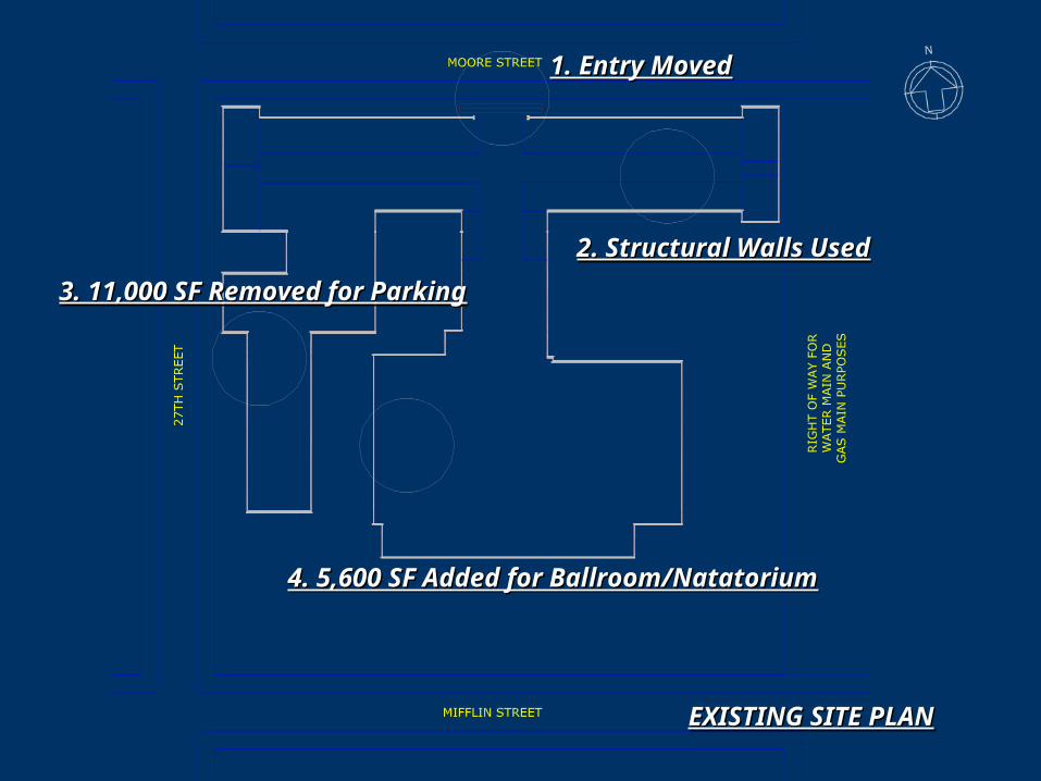
EXISTING SITE PLANEXISTING SITE PLAN
1. Entry Moved1. Entry Moved
2. Structural Walls Used2. Structural Walls Used
3. 11,000 SF Removed for Parking3. 11,000 SF Removed for Parking
4. 5,600 SF Added for Ballroom/Natatorium4. 5,600 SF Added for Ballroom/Natatorium

NEW SITE PLANNEW SITE PLAN

RESIDENTIAL SECTION – FLOOR PLANS 1, 2, 3RESIDENTIAL SECTION – FLOOR PLANS 1, 2, 3

COMMERCIAL SECTION COMMERCIAL SECTION 11STST FLOOR PLAN – BALLROOM FLOOR PLAN – BALLROOM

COMMERCIAL SECTION COMMERCIAL SECTION 22NDND FLOOR PLAN – NATATORIUM FLOOR PLAN – NATATORIUM

Architectural Program
Building Approx Ceiling WindowSection Floor Space Quantity Area (sf) Height (ft) Area (sf) Comments
Residential 1, 2, 3 Apartment Units 78 47,640 10 5,616 Assume an average of 4 windows
Residential 1, 2, 3 Studio Apartment 27 460 10 1,944 per apartment.
Residential 1, 2, 3 One Bedroom Apartment 30 600 10 2,160Residential 1, 2, 3 Deluxe One Bedroom Apartment 21 820 10 1,512 Assume each window = 18 sf
Residential 1, 2, 3 Common Areas n/a 47,343 10 648 Total Residential Space 94,983 6,264 See floor plans for window locations
Commercial 1, 2 Common Areas n/a 24,144 13 2,556 Assume each window = 18 sf
Commercial 1 Ballroom 1 22,746 16 n/aCommercial 2 Indoor Pool 1 9,490 13 n/a Max Pool Depth = 6'-0"
Commercial 2 Pool Deck 1 13,310 13 828 Assume each window = 18 sf
Total Commercial Space 69,690 3,384 See floor plans for window locations
Total Building Space 164,673 9,648

HVACSYSTEM
OUTLINE:OUTLINE:Specific Design FocusResidential Area Problems/SolutionsNatatorium Design Problems/Solutions Optimal SolutionsEquipment Example

Design Focus – What To Design?
Residential vs. Commercial Areas
Wide Array of Problems
Residential = More Common
Focus will be on the Natatorium

Residential Areas
Design Parameters include:– Heating & Cooling during winter/summer– Low initial cost– Low operating cost– High efficiency
Assumptions: Basic options include: Split VAV Rooftop units or
PTAC Units Alternative with the highest efficiency and lowest
cost is the best solution
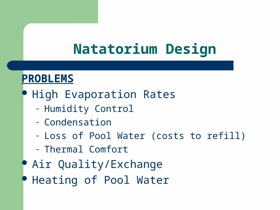
Natatorium Design
PROBLEMS High Evaporation Rates
– Humidity Control– Condensation– Loss of Pool Water (costs to refill)– Thermal Comfort
Air Quality/Exchange Heating of Pool Water
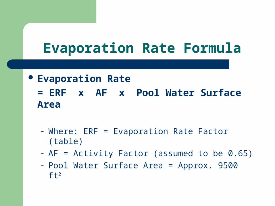
Evaporation Rate Formula
Evaporation Rate
= ERF x AF x Pool Water Surface Area
– Where: ERF = Evaporation Rate Factor (table)– AF = Activity Factor (assumed to be 0.65)– Pool Water Surface Area = Approx. 9500 ft2

Evaporation Rate Factor Table
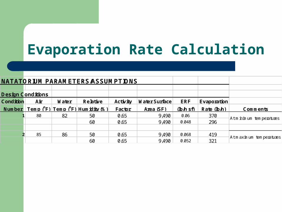
Evaporation Rate Calculation
NATATORIUM PARAMETERS/ASSUMPTIONS
Design ConditionsCondition Air Water Relative Activity Water Surface ERF Evaporation
Number Temp (oF) Temp (oF) Humidity (%) Factor Area (SF) (lb/h sf) Rate (lb/h) Comments1 80 82 50 0.65 9,490 0.06 370
60 0.65 9,490 0.048 296
2 85 86 50 0.65 9,490 0.068 41960 0.65 9,490 0.052 321
At minimum temperatures
At maximum temperatures
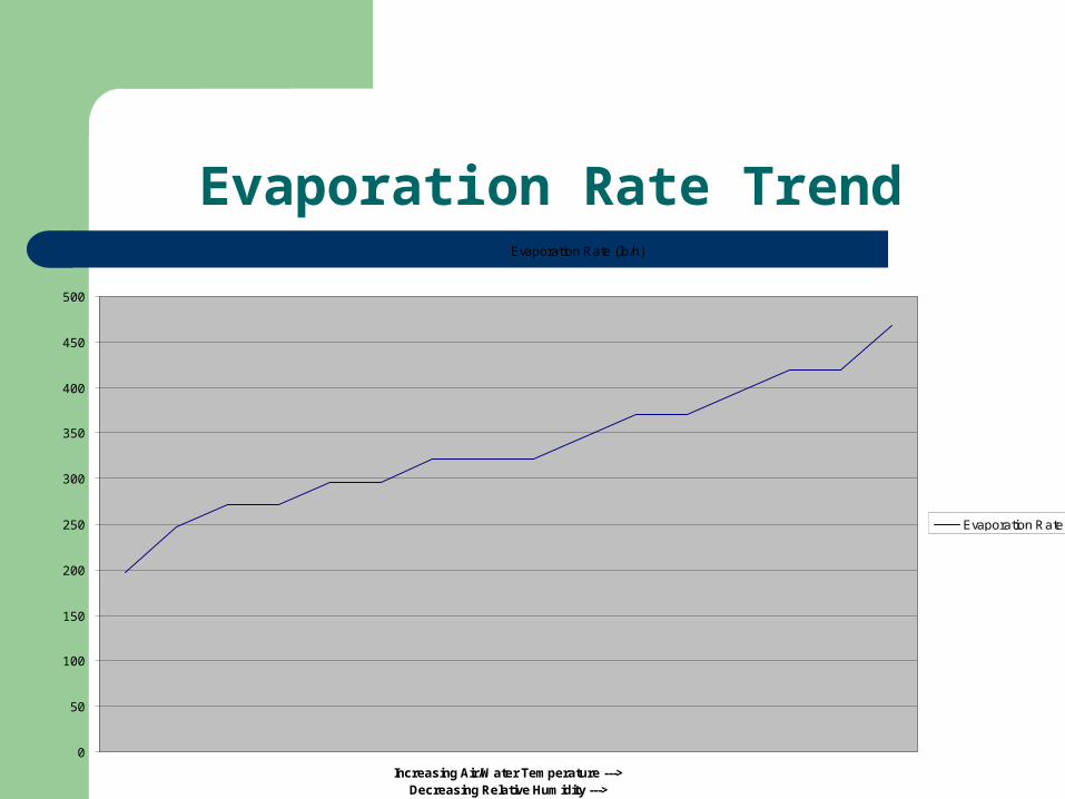
Evaporation Rate TrendEvaporation Rate (lb/h)
0
50
100
150
200
250
300
350
400
450
500
Increasing Air/Water Temperature --->Decreasing Relative Humidity --->
Evaporation Rate (lb/h)

Condensation
Windows– Recommended 3-5 CFM per SF of exterior glass– Therefore, natatorium requires 2,400-4,200 CFM
Walls, Ceilings, Other Thermal Bridges– Vapor Retarder
Proper Air Distribution is Key to Minimizing Damage– Minimize Eddy Effects Over Window (Mullions)– Minimize Air Flow Over Pool Surface

Loss of Pool Water The amount of condensate recovered in a year
by the HVAC system is approximately equal to one entire pool fill.
Condensate Calculations
Design ConditionsActive Inactive Active Inactive Total Total
Condition Evaporation Evaporation Active Inactive Evaporation Evaporation Evaporation Evaporation
Number Rate (gal/h) Rate (gal/h) Hours/day Hours/day Rate (gal/day) Rate (gal/day) Rate (gal/day) (gal/year)1 44 20 10 14 444 287 730 266,482
35 16 10 14 355 229 584 213,1862 50 23 10 14 503 325 827 302,013
38 18 10 14 384 248 633 230,951Average = 694 253,158
Pool DimensionsApprox Avg Pool Approx Approx
Space Area (sf) Depth (ft) Volume (cf) Volume (gal)
Pool Water 9,490 4 37,960 283,979

Air Quality & Air Exchange
ASHRAE Recommendations:
– 0.5 CFM of Outside air per FT2 of pool and wet deck Area… (For us, approx 4,800 CFM)
– 15 CFM of Outside air per spectator/user… (For us, assume above is larger)
– 4-6 Air Changes per Hour… (vs. 6-8 for spectator facilities)
– 13 – 37 Pa of Negative Pressure (We will use multiple exhaust fans)
– Must be able to purge if necessary
Pool Water Heating
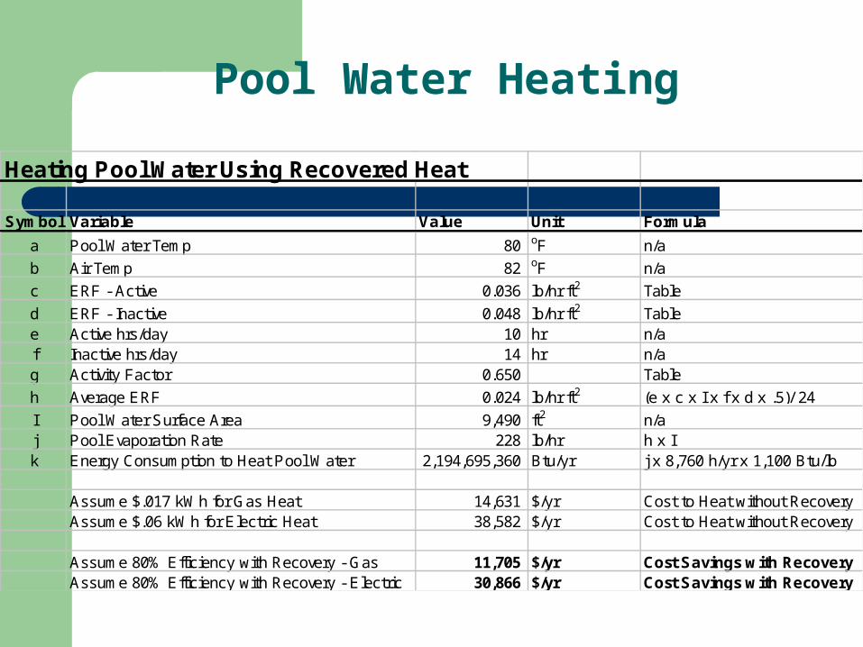
Heating Pool Water Using Recovered Heat
Symbol Variable Value Unit Formula
a Pool Water Temp 80 oF n/a
b Air Temp 82 oF n/a
c ERF - Active 0.036 lb/hr ft2 Table
d ERF - Inactive 0.048 lb/hr ft2 Tablee Active hrs/day 10 hr n/af Inactive hrs/day 14 hr n/ag Activity Factor 0.650 Table
h Average ERF 0.024 lb/hr ft2 (e x c x I x f x d x .5)/ 24
I Pool Water Surface Area 9,490 ft2 n/aj Pool Evaporation Rate 228 lb/hr h x Ik Energy Consumption to Heat Pool Water 2,194,695,360 Btu/yr j x 8,760 h/yr x 1,100 Btu/lb
Assume $.017 kWh for Gas Heat 14,631 $/yr Cost to Heat without RecoveryAssume $.06 kWh for Electric Heat 38,582 $/yr Cost to Heat without Recovery
Assume 80% Efficiency with Recovery - Gas 11,705 $/yr Cost Savings with RecoveryAssume 80% Efficiency with Recovery - Electric 30,866 $/yr Cost Savings with Recovery

Basic Equipment Example

Pool Design

Design of a Swimming Pool
Swimming pool on the 2nd floor Dimensions:
- 30ft by 90ft
- 6ft deep

Considerations
Water in pool become heavy loads
62.4 lb/ft x 30ft wide x 90ft long x 6ft deep =
A total of 1,010,880 lbs
Architectural Considerations
- Sizes of structural members- Column spacing

Structural System
- Pick a system that can handle heavy loads
and is efficient:

Structural System : Option 1
One-way Joist Slab- Joists act as t- beams to distribute the loads to the
girders- Span 15 to 36 ft- Economical system for heavy
loads or long spans

Structural System : Option 2
1. Concrete Waffle Slab - Because there are joists in both directions, this
floor system is the strongest and will have the least deflection
- 20 to 50 ft spans- Good for high gravity loads- High stiffness- Small deflections- Expensive due to formwork
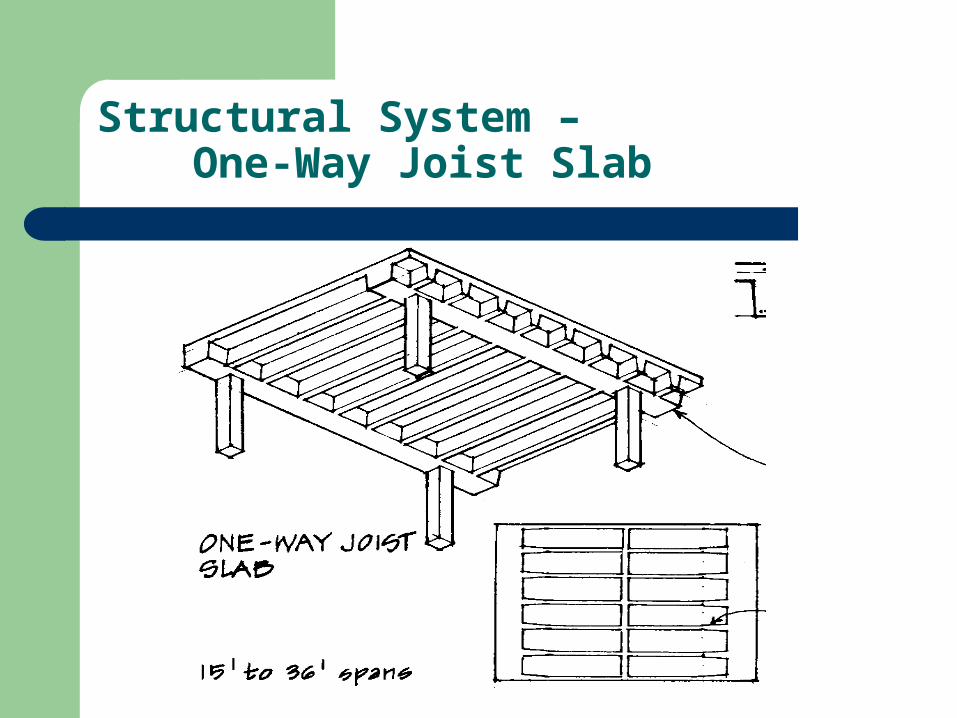
Structural System – One-Way Joist Slab

Slab Design
ACI requires for the height of slab to be at leastHeight = (Length of span)/20
In our case ----- Minimum Height = 3.6 “
*But Code requires a 6” slab for in our design for fire requirements*

Slab Design
Live Loads: Water Dead Load: Weight of concrete slab 6” slab Reinforcement
- # 4 @ 12” O.C ACI Requirement –
Ends of slab (length of span)/4 & Interior Spans (length of span)*(.3)
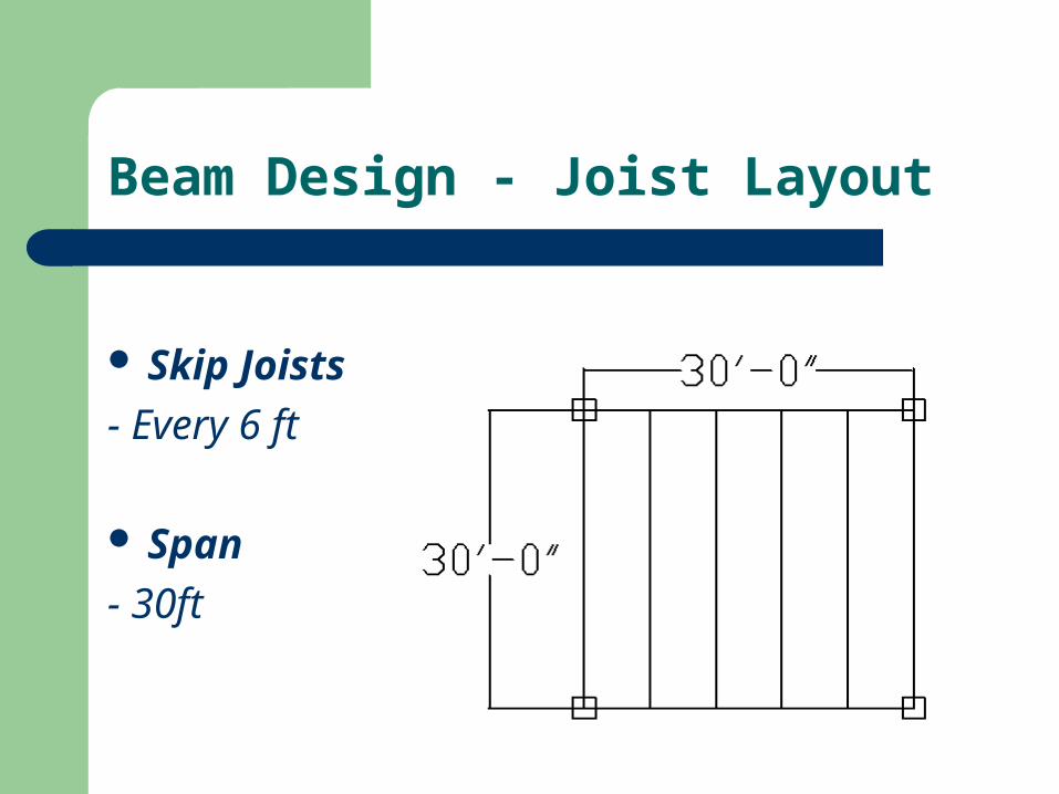
Beam Design - Joist Layout
Skip Joists
- Every 6 ft
Span
- 30ft

Trial Structural System Sizing
Joists
Width Depth Weight/ft
11 38 0.43
10 36 0.37
10 34 0.35
11 32 0.367
12 30 0.375
14 28 0.408
Girders
Width Depth Weight/ft
16 38 0.61
18 36 0.675
20 34 0.7
22 32 0.73
26 30 0.81
30 28 0.875
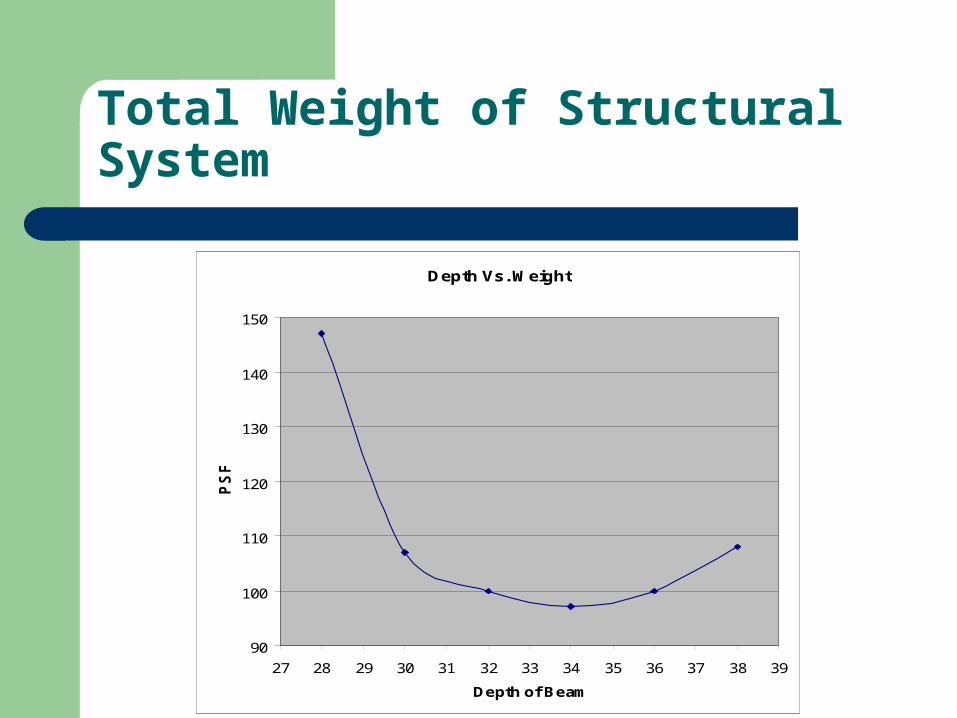
Total Weight of Structural System
Depth Vs. Weight
90
100
110
120
130
140
150
27 28 29 30 31 32 33 34 35 36 37 38 39
Depth of Beam
PS
F

Joists
Mu = 515.7 ft-kips Span = 30 ft Dimensions
B = 11”
D = 32” Reinforcement
- 6 #7’s
- # 3 Stirrups
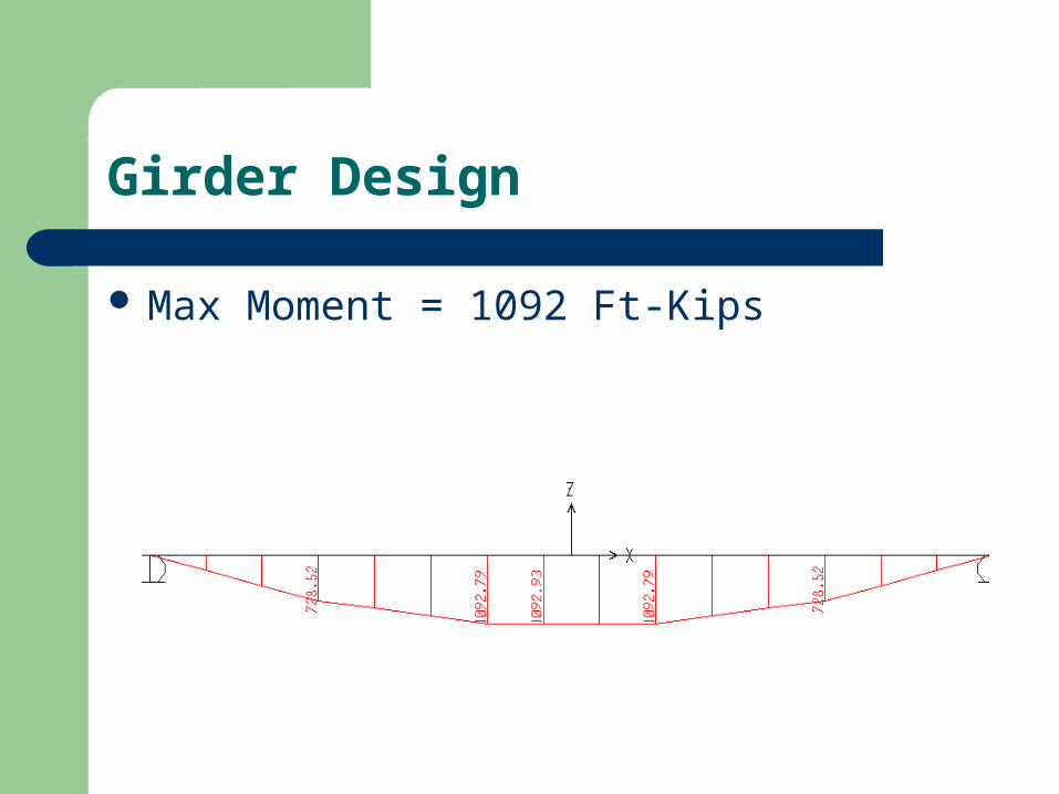
Girder Design
Max Moment = 1092 Ft-Kips
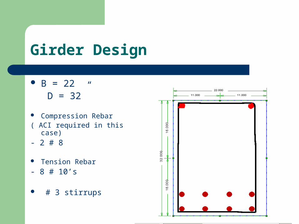
Girder Design
B = 22” D = 32”
Compression Rebar( ACI required in this case)
- 2 # 8
Tension Rebar
- 8 # 10’s
# 3 stirrups

Column Design
Column layout

Column Design
Dimension
18” x 18”
11 ft high Reinforcement
8 # 9’s
# 3 Ties According to code
Spacing = 18”

Column Interaction Diagram
Evaluation of the strength of the column subjected to combined bending and axial loads
Balanced Failure limit @
P = 400 kips
M = 250 ft-kips
Interaction Diagram
-600
-400
-200
0
200
400
600
800
1000
0 50 100 150 200 250 300
Phi M
Ph
i Lo
ad

Stormwater Detention/Retention

Why retain stormwater?
Impervious surfaces High runoff flow High river flow Erosion of stream banks Altered groundwater
tables Contamination of streams
– Carried from streets– Turbidity Schuylkill River bank on Kelly Drive

Drainage
Crest of the field Roof and lot
drainage to site storm drains
Swales direct current around field to basin

Regulations
Philadelphia City Codes 1 inch must be infiltrated Detention design for 100 year storm Only storm water may enter drainage pipes Design so that post-development infiltration
equals pre-development infiltration

Specs
Reference: 100 year storm with duration of 1 hour (duration assumption based on size and slope of parcel)
Area=379146.24ft2
-Half of the area is the impervious parking lot and roof, the other half is the football and baseball fields
Soil Class C-Soils having slow infiltration rates if thoroughly wetted and consisting chiefly of soils with a layer that impedes the downward movement of water, or soils with moderately fine to fine texture. They have a slow rate of water transmission.

Storm Analysis Design for 100 year storm Duration 1 hour (based on size and slope of parcel) Rainfall Depth 3.25 inches from chart
RETURN PERIODS OF EXTREME RAINFALLS @ PHILADELPHIA, PA(data from NWS Tech Paper #40, analysis by J. Richard Weggel, Ph.D., P.E.)
0.0
2.0
4.0
6.0
8.0
10.0
12.0
14.0
1 10 100 1000 10000
RETURN PERIOD (years)
24 HOUR RAINFALL12 HOUR RAINFALL6 HOUR RAINFALL3 HOUR RAINFALL2 HOUR RAINFALL1 HOUR RAINFALL1/2 HOUR RAINFALL
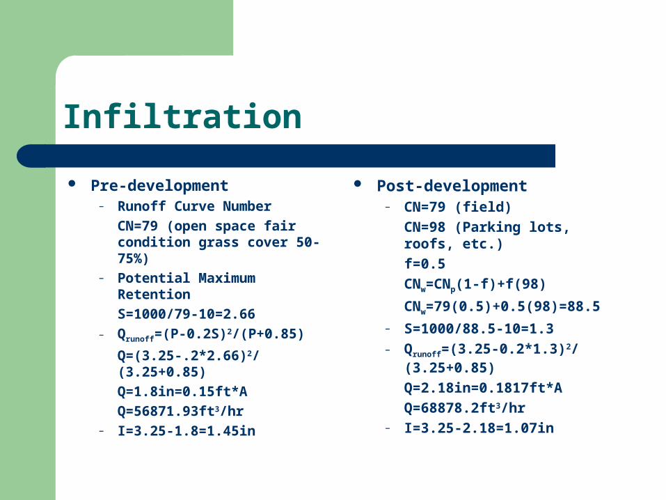
Infiltration
Pre-development– Runoff Curve Number
CN=79 (open space fair condition grass cover 50-75%)
– Potential Maximum Retention
S=1000/79-10=2.66– Qrunoff=(P-0.2S)2/(P+0.85)
Q=(3.25-.2*2.66)2/(3.25+0.85)
Q=1.8in=0.15ft*A
Q=56871.93ft3/hr– I=3.25-1.8=1.45in
Post-development– CN=79 (field)
CN=98 (Parking lots, roofs, etc.)
f=0.5
CNw=CNp(1-f)+f(98)
CNw=79(0.5)+0.5(98)=88.5
– S=1000/88.5-10=1.3– Qrunoff=(3.25-0.2*1.3)2/
(3.25+0.85)
Q=2.18in=0.1817ft*A
Q=68878.2ft3/hr– I=3.25-2.18=1.07in

Underground Basin Design
Qpost-Qpre=68878.2-56871.9=12006.3ft3/hr Must re-infiltrate this volume. Design a detention basin with two tanks with weir flow from storage
tank to discharge tank Weir 1ft wide by 10ft tall by 60ft long=600ft3
Storage Tank 20ft wide by 10ft tall by 60ft long=12000ft3
Entire Tank 77ft wide by 15ft tall by 60ft long=69300ft3
Maximum volume of basin=69300-600=68700ft3
Storage Tank will supply sprinkler system Discharge to storm sewer at Mifflin Street

Underground Basin
57ft 20ft
60ft
10ft
5ft
Re-infiltration
Storage tank supplies sprinkler system when it contains water Rotary sprinklers will apply about 0.7in/hr to fields over a radius
of 50ft The area of the field divided by the area covered by sprinklers
indicates that 25 rotary head sprinklers will be needed to sufficiently reapply the contained storm water
Sprinklers run for a very short time so that runoff is minimized during operation
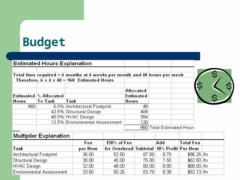
Budget

Budget