renovation of spectronic-20 by integrating a raspberry pi...
TRANSCRIPT

H-SC Journal of Sciences (2017) Vol. VI McGaughey and Anderson
http://sciencejournal.hsc.edu/
Renovation of Spectronic-20 by Integrating a Raspberry Pi Computing System Tyler A. McGaughey ’18 and C. William Anderson
Department of Chemistry, Hampden-Sydney College, Hampden-Sydney, VA 23943
INTRODUCTION
The purpose of this project was to renovate a Spectronic 20. The Spectronic-20 when it originally came out in the 1950’s was a revolutionary instrument. It opened many doors because of its low cost. Over the course of production approximately 600,000 were made.1 Due to the low cost and relatively large production numbers many high schools and college were able to acquire one. However, as technologies advanced they fell by the wayside. The Spectronic 20 relies primarily on vacuum tubes, which can take up to half an hour to warm up. This caused them to be put in storage closets and forgot about. The instrument also takes a lot of skill to use. This project’s goal was to turn a functioning antiquated instrument into a user friendly, modern instrument.
HARDWARE
The first portion of this project focused on the
hardware or the actual instrument its self. The Spectronic 20 is a spectrophotometer. Which means it uses light to analyze a sample. The optics inside the instrument are still viable. Figure 1 explains the light’s path through the instrument.
Figure 1 - Optics Diagram2
Light is first emitted from the light source. It
then passes through a lens for focusing then a prism for grating. The technician has a dial to adjust the wavelength of light that goes to the sample. This is useful because samples absorb different wavelengths of light based on color. After the light passes through the sample it hits the photo detector. The signal then goes from the photo detector to the electronics, which translate it into a percent absorbance. That information is then displayed on a needle display. Figure 2 shows the current exterior of the instrument.
Figure 2 – Exterior
First the instrument was completely
eviscerated except the optics. Figure 3 shows the internal components prior to overhaul.
Figure 3 - Internal Mechanisms
After overhaul, new components were put
into the shell of the instrument starting with the photo detector. It is responsible for quantifying the photons of photons its sees and transferring that information to a computing system. Figure 4 shows the old photo detector.

H-SC Journal of Sciences (2017) Vol. VI McGaughey and Anderson
http://sciencejournal.hsc.edu/
Figure 4 – Old Photo Detector
This project utilized the TSL2591 high
dynamic range digital light sensor. This sensor is rated for both infrared and visible light spectra. The sensor is rated for light from 420nm to 1050nm.3 This sensor is perfect for the project for a number of reasons. The first is its low cost, under ten dollars.4 Second are its wide spectra abilities. Lastly, is the easy interface via i2c with the Raspberry Pi. Figure 5 shows the TSL2591 sensor.
Figure 5 – TSL2591 Sensor 4
This sensor was mounted in the light beam
path behind the sample and connected with wires to the general-purpose input/output (GPIO) pins on the Raspberry Pi. A Raspberry Pi 3 was utilized in this project for a number of reasons. The first is the low cost, under forty dollars.5 Keeping in line with the goal of the project to get these instruments back into the classroom easily and most importantly at a low cost. The next reason is the great versatility of the system. There are endless programing opportunities since the Pi comes from the manufacturer blank. It is up to the consumer to write and program an operating system or code. The third reason is the number of input types. The Raspberry Pi 3 comes with built in Bluetooth, Wi-Fi, HDMI port, four USB ports, Ethernet port, and forty GPIO. It also comes with a 1.2 GHz Quad Core Broadcom BCM2837 64-bit ARMv8 processor giving it a respectable amount of processing power.5
Figure 6 – Raspberry Pi 3 5
The aforementioned features of the Raspberry Pi allow for easy use of the instrument. The Wi-Fi capabilities provide the technician operating the renovated instrument with a number of new capabilities, for instance the ability to email data to a professor or wireless interfacing for diagnostics. The Bluetooth capabilities allow for the use of a wireless mouse and keyboard. Lastly, the HDMI port allows for the incorporation of a LCD (liquid crystal display). After the hardware was in place the software was developed. SOFTWARE
As stated earlier all Raspberry Pi’s come from the manufacturer blank. It is up to the user install their own operating system. The Raspberry Pi foundation has several open source operating systems designed specifically for the Raspberry Pi. The most commonly used one is called Raspbian.6 This software is downloaded onto a micro-SD card and then loaded into the slot on the Raspberry Pi. Raspbian provides a simple desktop and a terminal for python coding. All coding for this project was done using the python language. The initial python code to run the TSL2591 sensor was derived from an open source repository.7 That code is listed in the code appendices. That code was then transformed and reworked to make it more user-friendly. The original script only outputs one lux value. This project developed a code that is much easier for the technician to use. The python script opens a blank document then creates a header consisting of Hampden Sydney College, the current time, and the wavelength of the current test in progress. The script then prompts the researcher to remove all cuvettes so it can take a background light reading. It then prompts the researcher to insert a cuvette filled with deionized water. This allows the
H-SC Journal of Sciences (2017) Vol. VI McGaughey and Anderson
http://sciencejournal.hsc.edu/
instrument to take a max light reading. The instrument then prompts the researcher to insert the cuvette with the sample. It then outputs three light values in Lux. See the second entry in the code appendices for the full code. After both the hardware and software were in place it was time to test the newly renovated instrument. TESTING
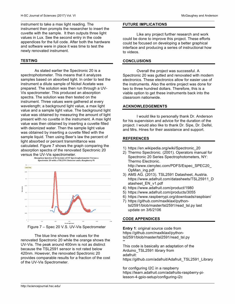
As stated earlier the Spectronic 20 is a spectrophotometer. This means that it analyzes samples based on absorbed light. In order to test the instrument a dilute sample of Nickel Acetate was prepared. The solution was then run through a UV-Vis spectrometer. This produced an absorption spectra. The solution was then tested on the instrument. Three values were gathered at every wavelength; a background light value, a max light value and a sample light value. The background light value was obtained by measuring the amount of light present with no cuvette in the instrument. A max light value was then obtained by inserting a cuvette filled with deionized water. Then the sample light value was obtained by inserting a cuvette filled with the sample liquid. Then using Beer’s law the percent of light absorbed or percent transmittance was calculated. Figure 7 shows the graph comparing the absorption spectra of the renovated Spectronic 20 versus the UV-Vis spectrometer.
Figure 7 – Spec 20 V.S. UV-Vis Spectrometer
The blue line shows the values for the
renovated Spectronic 20 while the orange shows the UV-Vis. The peak around 400nm is not as distinct because the TSL2591 sensor is not rated below 420nm. However, the renovated Spectronic 20 provides comparable results for a fraction of the cost of the UV-Vis Spectrometer.
FUTURE IMPLICATIONS Like any project further research and work
could be done to improve this project. These efforts could be focused on developing a better graphical interface and producing a series of instructional how to videos.
CONCLUSIONS
Overall the project was successful. A
Spectronic 20 was gutted and renovated with modern electronics. These electronics allow for easier use of the instruments. Also the entire project was done for two to three hundred dollars. Therefore, this is a viable option to get these instruments back into the classroom nationwide.
ACKNOWLEDGEMENTS
I would like to personally thank Dr. Anderson for his supervision and advice for the duration of the project. I would also like to thank Dr. Sipe, Dr. Deifel, and Mrs. Hines for their assistance and support.
REFERENCES 1) https://en.wikipedia.org/wiki/Spectronic_20 2) Thermo Spectronic. (2001). Operators manual for
Spectronic 20 Series Spectrophotometers, NY: Thermo Electronic. http://www.cienytec.com/PDFS/Espec_SPEC20_OpMan_ing.pdf
3) AMS AG. (2013). TSL2591 Datasheet, Austria. https://www.adafruit.com/datasheets/TSL25911_Datasheet_EN_v1.pdf
4) https://www.adafruit.com/product/1980 5) https://www.adafruit.com/products/3055 6) https://www.raspberrypi.org/downloads/raspbian/ 7) https://github.com/maxlklaxl/python-
tsl2591/blob/master/tsl2591/read_tsl.py last update on 3/6/2106
CODE APPENDICES Entry 1: original source code from https://github.com/maxlklaxl/python-tsl2591/blob/master/tsl2591/read_tsl.py ''' This code is basically an adaptation of the Arduino_TSL2591 library from adafruit: https://github.com/adafruit/Adafruit_TSL2591_Library for configuring I2C in a raspberry https://learn.adafruit.com/adafruits-raspberry-pi-lesson-4-gpio-setup/configuring-i2c
H-SC Journal of Sciences (2017) Vol. VI McGaughey and Anderson
http://sciencejournal.hsc.edu/
datasheet: http://ams.com/eng/Products/Light-Sensors/Light-to-Digital-Sensors/TSL25911 ''' import smbus import time VISIBLE = 2 # channel 0 - channel 1 INFRARED = 1 # channel 1 FULLSPECTRUM = 0 # channel 0 ADDR = 0x29 READBIT = 0x01 COMMAND_BIT = 0xA0 # bits 7 and 5 for 'command normal' CLEAR_BIT = 0x40 # Clears any pending interrupt (write 1 to clear) WORD_BIT = 0x20 # 1 = read/write word (rather than byte) BLOCK_BIT = 0x10 # 1 = using block read/write ENABLE_POWERON = 0x01 ENABLE_POWEROFF = 0x00 ENABLE_AEN = 0x02 ENABLE_AIEN = 0x10 CONTROL_RESET = 0x80 LUX_DF = 408.0 LUX_COEFB = 1.64 # CH0 coefficient LUX_COEFC = 0.59 # CH1 coefficient A LUX_COEFD = 0.86 # CH2 coefficient B REGISTER_ENABLE = 0x00 REGISTER_CONTROL = 0x01 REGISTER_THRESHHOLDL_LOW = 0x02 REGISTER_THRESHHOLDL_HIGH = 0x03 REGISTER_THRESHHOLDH_LOW = 0x04 REGISTER_THRESHHOLDH_HIGH = 0x05 REGISTER_INTERRUPT = 0x06 REGISTER_CRC = 0x08 REGISTER_ID = 0x0A REGISTER_CHAN0_LOW = 0x14 REGISTER_CHAN0_HIGH = 0x15 REGISTER_CHAN1_LOW = 0x16 REGISTER_CHAN1_HIGH = 0x17 INTEGRATIONTIME_100MS = 0x00 INTEGRATIONTIME_200MS = 0x01 INTEGRATIONTIME_300MS = 0x02 INTEGRATIONTIME_400MS = 0x03 INTEGRATIONTIME_500MS = 0x04 INTEGRATIONTIME_600MS = 0x05 GAIN_LOW = 0x00 # low gain (1x) GAIN_MED = 0x10 # medium gain (25x) GAIN_HIGH = 0x20 # medium gain (428x)
GAIN_MAX = 0x30 # max gain (9876x) class Tsl2591(object): def __init__( self, i2c_bus=1, sensor_address=0x29, integration=INTEGRATIONTIME_100MS, gain=GAIN_LOW ): self.bus = smbus.SMBus(i2c_bus) self.sendor_address = sensor_address self.integration_time = integration self.gain = gain self.set_timing(self.integration_time) self.set_gain(self.gain) self.disable() # to be sure def set_timing(self, integration): self.enable() self.integration_time = integration self.bus.write_byte_data( self.sendor_address, COMMAND_BIT | REGISTER_CONTROL, self.integration_time | self.gain ) self.disable() def get_timing(self): return self.integration_time def set_gain(self, gain): self.enable() self.gain = gain self.bus.write_byte_data( self.sendor_address, COMMAND_BIT | REGISTER_CONTROL, self.integration_time | self.gain ) self.disable() def get_gain(self): return self.gain def calculate_lux(self, full, ir): # Check for overflow conditions first if (full == 0xFFFF) | (ir == 0xFFFF): return 0 case_integ = { INTEGRATIONTIME_100MS: 100., INTEGRATIONTIME_200MS: 200.,

H-SC Journal of Sciences (2017) Vol. VI McGaughey and Anderson
http://sciencejournal.hsc.edu/
INTEGRATIONTIME_300MS: 300., INTEGRATIONTIME_400MS: 400., INTEGRATIONTIME_500MS: 500., INTEGRATIONTIME_600MS: 600., } if self.integration_time in case_integ.keys(): atime = case_integ[self.integration_time] else: atime = 100. case_gain = { GAIN_LOW: 1., GAIN_MED: 25., GAIN_HIGH: 428., GAIN_MAX: 9876., } if self.gain in case_gain.keys(): again = case_gain[self.gain] else: again = 1. # cpl = (ATIME * AGAIN) / DF cpl = (atime * again) / LUX_DF lux1 = (full - (LUX_COEFB * ir)) / cpl lux2 = ((LUX_COEFC * full) - (LUX_COEFD * ir)) / cpl # The highest value is the approximate lux equivalent return max([lux1, lux2]) def enable(self): self.bus.write_byte_data( self.sendor_address, COMMAND_BIT | REGISTER_ENABLE, ENABLE_POWERON | ENABLE_AEN | ENABLE_AIEN ) # Enable def disable(self): self.bus.write_byte_data( self.sendor_address, COMMAND_BIT | REGISTER_ENABLE, ENABLE_POWEROFF ) def get_full_luminosity(self): self.enable() time.sleep(0.120*self.integration_time+1) # not sure if we need it "// Wait x ms for ADC to complete" full = self.bus.read_word_data( self.sendor_address, COMMAND_BIT | REGISTER_CHAN0_LOW ) ir = self.bus.read_word_data( self.sendor_address, COMMAND_BIT | REGISTER_CHAN1_LOW
) self.disable() return full, ir def get_luminosity(self, channel): full, ir = self.get_full_luminosity() if channel == FULLSPECTRUM: # Reads two byte value from channel 0 (visible + infrared) return full elif channel == INFRARED: # Reads two byte value from channel 1 (infrared) return ir elif channel == VISIBLE: # Reads all and subtracts out ir to give just the visible! return full - ir else: # unknown channel! return 0 if __name__ == '__main__': tsl = Tsl2591() # initialize full, ir = tsl.get_full_luminosity() # read raw values (full spectrum and ir spectrum) lux = tsl.calculate_lux(full, ir) # convert raw values to lux print (lux, full, ir) print () def test(int_time=INTEGRATIONTIME_100MS, gain=GAIN_LOW): tsl.set_gain(gain) tsl.set_timing(int_time) full_test, ir_test = tsl.get_full_luminosity() lux_test = tsl.calculate_lux(full_test, ir_test) print ('Lux = %f full = %i ir = %i' % (lux_test, full_test, ir_test)) print("integration time = %i" % tsl.get_timing()) print("gain = %i \n" % tsl.get_gain()) for i in [INTEGRATIONTIME_100MS, INTEGRATIONTIME_200MS, INTEGRATIONTIME_300MS, INTEGRATIONTIME_400MS, INTEGRATIONTIME_500MS, INTEGRATIONTIME_600MS]: test(i, GAIN_LOW) for i in [GAIN_LOW, GAIN_MED, GAIN_HIGH, GAIN_MAX]: test(INTEGRATIONTIME_100MS, i) Entry 2: This projects python code print "Hampden Sydney College" import datetime

H-SC Journal of Sciences (2017) Vol. VI McGaughey and Anderson
http://sciencejournal.hsc.edu/
now = datetime.datetime.now() print now.strftime("%Y-%m-%d %H:%M") fob=open('/home/pi/data.txt','a') fob.write(" \n") fob.write(" \n") fob.write('Hampden Sydney College\n') fob.write(now.strftime("%Y-%m-%d %H:%M\n")) wavelength = raw_input("What wavelength is this test preformed at? ") print "Wavelength = %r" % (wavelength) fob.write("Wavelength = %r" % (wavelength)) fob.write(" \n") fob.close() ################blank################################ blank = raw_input("Remove cuvette to run background, press ENTER to continue.") print 'Measuring Background Readings, Please wait.' import smbus import time VISIBLE = 2 # channel 0 - channel 1 INFRARED = 1 # channel 1 FULLSPECTRUM = 0 # channel 0 ADDR = 0x29 READBIT = 0x01 COMMAND_BIT = 0xA0 # bits 7 and 5 for 'command normal' CLEAR_BIT = 0x40 # Clears any pending interrupt (write 1 to clear) WORD_BIT = 0x20 # 1 = read/write word (rather than byte) BLOCK_BIT = 0x10 # 1 = using block read/write ENABLE_POWERON = 0x01 ENABLE_POWEROFF = 0x00 ENABLE_AEN = 0x02 ENABLE_AIEN = 0x10 CONTROL_RESET = 0x80 LUX_DF = 408.0 LUX_COEFB = 1.64 # CH0 coefficient LUX_COEFC = 0.59 # CH1 coefficient A LUX_COEFD = 0.86 # CH2 coefficient B REGISTER_ENABLE = 0x00 REGISTER_CONTROL = 0x01 REGISTER_THRESHHOLDL_LOW = 0x02 REGISTER_THRESHHOLDL_HIGH = 0x03 REGISTER_THRESHHOLDH_LOW = 0x04 REGISTER_THRESHHOLDH_HIGH = 0x05 REGISTER_INTERRUPT = 0x06
REGISTER_CRC = 0x08 REGISTER_ID = 0x0A REGISTER_CHAN0_LOW = 0x14 REGISTER_CHAN0_HIGH = 0x15 REGISTER_CHAN1_LOW = 0x16 REGISTER_CHAN1_HIGH = 0x17 INTEGRATIONTIME_100MS = 0x00 INTEGRATIONTIME_200MS = 0x01 INTEGRATIONTIME_300MS = 0x02 INTEGRATIONTIME_400MS = 0x03 INTEGRATIONTIME_500MS = 0x04 INTEGRATIONTIME_600MS = 0x05 GAIN_HIGH = 0x20 # medium gain (428x) class Tsl2591(object): def __init__( self, i2c_bus=1, sensor_address=0x29, integration=INTEGRATIONTIME_100MS, gain=GAIN_HIGH ): self.bus = smbus.SMBus(i2c_bus) self.sendor_address = sensor_address self.integration_time = integration self.gain = gain self.set_timing(self.integration_time) self.set_gain(self.gain) self.disable() # to be sure def set_timing(self, integration): self.enable() self.integration_time = integration self.bus.write_byte_data( self.sendor_address, COMMAND_BIT | REGISTER_CONTROL, self.integration_time | self.gain ) self.disable() def get_timing(self): return self.integration_time def set_gain(self, gain): self.enable() self.gain = gain self.bus.write_byte_data( self.sendor_address, COMMAND_BIT | REGISTER_CONTROL, self.integration_time | self.gain ) self.disable()
H-SC Journal of Sciences (2017) Vol. VI McGaughey and Anderson
http://sciencejournal.hsc.edu/
def get_gain(self): return self.gain def calculate_lux(self, full, ir): # Check for overflow conditions first if (full == 0xFFFF) | (ir == 0xFFFF): return 0 case_integ = { INTEGRATIONTIME_100MS: 100., INTEGRATIONTIME_200MS: 200., INTEGRATIONTIME_300MS: 300., INTEGRATIONTIME_400MS: 400., INTEGRATIONTIME_500MS: 500., INTEGRATIONTIME_600MS: 600., } if self.integration_time in case_integ.keys(): atime = case_integ[self.integration_time] else: atime = 100. case_gain = {GAIN_HIGH: 428.} if self.gain in case_gain.keys(): again = case_gain[self.gain] else: again = 1. # cpl = (ATIME * AGAIN) / DF cpl = (atime * again) / LUX_DF lux1 = (full - (LUX_COEFB * ir)) / cpl lux2 = ((LUX_COEFC * full) - (LUX_COEFD * ir)) / cpl # The highest value is the approximate lux equivalent return max([lux1, lux2]) def enable(self): self.bus.write_byte_data( self.sendor_address, COMMAND_BIT | REGISTER_ENABLE, ENABLE_POWERON | ENABLE_AEN | ENABLE_AIEN ) # Enable def disable(self): self.bus.write_byte_data( self.sendor_address, COMMAND_BIT | REGISTER_ENABLE, ENABLE_POWEROFF ) def get_full_luminosity(self): self.enable() time.sleep(0.120*self.integration_time+1) # not sure if we need it "// Wait x ms for ADC to complete"
full = self.bus.read_word_data( self.sendor_address, COMMAND_BIT | REGISTER_CHAN0_LOW ) ir = self.bus.read_word_data( self.sendor_address, COMMAND_BIT | REGISTER_CHAN1_LOW ) self.disable() return full, ir def get_luminosity(self, channel): full, ir = self.get_full_luminosity() if channel == FULLSPECTRUM: # Reads two byte value from channel 0 (visible + infrared) return full elif channel == INFRARED: # Reads two byte value from channel 1 (infrared) return ir elif channel == VISIBLE: # Reads all and subtracts out ir to give just the visible! return full - ir else: # unknown channel! return 0 if __name__ == '__main__': tsl = Tsl2591() # initialize full, ir = tsl.get_full_luminosity() # read raw values (full spectrum and ir spectrum) lux = tsl.calculate_lux(full, ir) # convert raw values to lux def test(int_time=INTEGRATIONTIME_100MS, gain=GAIN_HIGH): tsl.set_gain(gain) tsl.set_timing(int_time) full_test, ir_test = tsl.get_full_luminosity() lux_test = tsl.calculate_lux(full_test, ir_test) fob=open('/home/pi/data.txt','a') fob.write(" \n") fob.write('Background Reading\n') fob.write('full = %i\n' % (full_test)) fob.write("integration time = %i\n" % tsl.get_timing()) fob.write("gain = %i \n" % tsl.get_gain()) fob.close() print ('full = %i' % (full_test)) print("integration time = %i" % tsl.get_timing()) print("gain = %i \n" % tsl.get_gain()) for i in [INTEGRATIONTIME_200MS]: test(i, GAIN_HIGH) ##############Max############################
H-SC Journal of Sciences (2017) Vol. VI McGaughey and Anderson
http://sciencejournal.hsc.edu/
upper = raw_input("Insert cuvette with DiH2O to establish max light value, press ENTER to continue.") print 'Measuring Upper Bound Readings, Please wait.' import smbus import time VISIBLE = 2 # channel 0 - channel 1 INFRARED = 1 # channel 1 FULLSPECTRUM = 0 # channel 0 ADDR = 0x29 READBIT = 0x01 COMMAND_BIT = 0xA0 # bits 7 and 5 for 'command normal' CLEAR_BIT = 0x40 # Clears any pending interrupt (write 1 to clear) WORD_BIT = 0x20 # 1 = read/write word (rather than byte) BLOCK_BIT = 0x10 # 1 = using block read/write ENABLE_POWERON = 0x01 ENABLE_POWEROFF = 0x00 ENABLE_AEN = 0x02 ENABLE_AIEN = 0x10 CONTROL_RESET = 0x80 LUX_DF = 408.0 LUX_COEFB = 1.64 # CH0 coefficient LUX_COEFC = 0.59 # CH1 coefficient A LUX_COEFD = 0.86 # CH2 coefficient B REGISTER_ENABLE = 0x00 REGISTER_CONTROL = 0x01 REGISTER_THRESHHOLDL_LOW = 0x02 REGISTER_THRESHHOLDL_HIGH = 0x03 REGISTER_THRESHHOLDH_LOW = 0x04 REGISTER_THRESHHOLDH_HIGH = 0x05 REGISTER_INTERRUPT = 0x06 REGISTER_CRC = 0x08 REGISTER_ID = 0x0A REGISTER_CHAN0_LOW = 0x14 REGISTER_CHAN0_HIGH = 0x15 REGISTER_CHAN1_LOW = 0x16 REGISTER_CHAN1_HIGH = 0x17 INTEGRATIONTIME_100MS = 0x00 INTEGRATIONTIME_200MS = 0x01 INTEGRATIONTIME_300MS = 0x02 INTEGRATIONTIME_400MS = 0x03 INTEGRATIONTIME_500MS = 0x04 INTEGRATIONTIME_600MS = 0x05 GAIN_HIGH = 0x20 # medium gain (428x) class Tsl2591(object): def __init__( self,
i2c_bus=1, sensor_address=0x29, integration=INTEGRATIONTIME_100MS, gain=GAIN_HIGH ): self.bus = smbus.SMBus(i2c_bus) self.sendor_address = sensor_address self.integration_time = integration self.gain = gain self.set_timing(self.integration_time) self.set_gain(self.gain) self.disable() # to be sure def set_timing(self, integration): self.enable() self.integration_time = integration self.bus.write_byte_data( self.sendor_address, COMMAND_BIT | REGISTER_CONTROL, self.integration_time | self.gain ) self.disable() def get_timing(self): return self.integration_time def set_gain(self, gain): self.enable() self.gain = gain self.bus.write_byte_data( self.sendor_address, COMMAND_BIT | REGISTER_CONTROL, self.integration_time | self.gain ) self.disable() def get_gain(self): return self.gain def calculate_lux(self, full, ir): # Check for overflow conditions first if (full == 0xFFFF) | (ir == 0xFFFF): return 0 case_integ = { INTEGRATIONTIME_100MS: 100., INTEGRATIONTIME_200MS: 200., INTEGRATIONTIME_300MS: 300., INTEGRATIONTIME_400MS: 400., INTEGRATIONTIME_500MS: 500., INTEGRATIONTIME_600MS: 600., } if self.integration_time in case_integ.keys():

H-SC Journal of Sciences (2017) Vol. VI McGaughey and Anderson
http://sciencejournal.hsc.edu/
atime = case_integ[self.integration_time] else: atime = 100. case_gain = {GAIN_HIGH: 428.} if self.gain in case_gain.keys(): again = case_gain[self.gain] else: again = 1. # cpl = (ATIME * AGAIN) / DF cpl = (atime * again) / LUX_DF lux1 = (full - (LUX_COEFB * ir)) / cpl lux2 = ((LUX_COEFC * full) - (LUX_COEFD * ir)) / cpl # The highest value is the approximate lux equivalent return max([lux1, lux2]) def enable(self): self.bus.write_byte_data( self.sendor_address, COMMAND_BIT | REGISTER_ENABLE, ENABLE_POWERON | ENABLE_AEN | ENABLE_AIEN ) # Enable def disable(self): self.bus.write_byte_data( self.sendor_address, COMMAND_BIT | REGISTER_ENABLE, ENABLE_POWEROFF ) def get_full_luminosity(self): self.enable() time.sleep(0.120*self.integration_time+1) # not sure if we need it "// Wait x ms for ADC to complete" full = self.bus.read_word_data( self.sendor_address, COMMAND_BIT | REGISTER_CHAN0_LOW ) ir = self.bus.read_word_data( self.sendor_address, COMMAND_BIT | REGISTER_CHAN1_LOW ) self.disable() return full, ir def get_luminosity(self, channel): full, ir = self.get_full_luminosity() if channel == FULLSPECTRUM: # Reads two byte value from channel 0 (visible + infrared) return full elif channel == INFRARED:
# Reads two byte value from channel 1 (infrared) return ir elif channel == VISIBLE: # Reads all and subtracts out ir to give just the visible! return full - ir else: # unknown channel! return 0 if __name__ == '__main__': tsl = Tsl2591() # initialize full, ir = tsl.get_full_luminosity() # read raw values (full spectrum and ir spectrum) lux = tsl.calculate_lux(full, ir) # convert raw values to lux def test(int_time=INTEGRATIONTIME_100MS, gain=GAIN_HIGH): tsl.set_gain(gain) tsl.set_timing(int_time) full_test, ir_test = tsl.get_full_luminosity() lux_test = tsl.calculate_lux(full_test, ir_test) fob=open('/home/pi/data.txt','a') fob.write(" \n") fob.write('Max Reading\n') fob.write('full = %i\n' % (full_test)) fob.write("integration time = %i\n" % tsl.get_timing()) fob.write("gain = %i \n" % tsl.get_gain()) fob.close() print ('full = %i' % (full_test)) print("integration time = %i" % tsl.get_timing()) print("gain = %i \n" % tsl.get_gain()) for i in [INTEGRATIONTIME_200MS]: test(i, GAIN_HIGH) ##################Sample############################### sample = raw_input("Insert cuvette with sample to run sample, press ENTER to continue.") print 'Measuring Sample Readings, Please wait.' import smbus import time VISIBLE = 2 # channel 0 - channel 1 INFRARED = 1 # channel 1 FULLSPECTRUM = 0 # channel 0 ADDR = 0x29 READBIT = 0x01 COMMAND_BIT = 0xA0 # bits 7 and 5 for 'command normal' CLEAR_BIT = 0x40 # Clears any pending interrupt (write 1 to clear)

H-SC Journal of Sciences (2017) Vol. VI McGaughey and Anderson
http://sciencejournal.hsc.edu/
WORD_BIT = 0x20 # 1 = read/write word (rather than byte) BLOCK_BIT = 0x10 # 1 = using block read/write ENABLE_POWERON = 0x01 ENABLE_POWEROFF = 0x00 ENABLE_AEN = 0x02 ENABLE_AIEN = 0x10 CONTROL_RESET = 0x80 LUX_DF = 408.0 LUX_COEFB = 1.64 # CH0 coefficient LUX_COEFC = 0.59 # CH1 coefficient A LUX_COEFD = 0.86 # CH2 coefficient B REGISTER_ENABLE = 0x00 REGISTER_CONTROL = 0x01 REGISTER_THRESHHOLDL_LOW = 0x02 REGISTER_THRESHHOLDL_HIGH = 0x03 REGISTER_THRESHHOLDH_LOW = 0x04 REGISTER_THRESHHOLDH_HIGH = 0x05 REGISTER_INTERRUPT = 0x06 REGISTER_CRC = 0x08 REGISTER_ID = 0x0A REGISTER_CHAN0_LOW = 0x14 REGISTER_CHAN0_HIGH = 0x15 REGISTER_CHAN1_LOW = 0x16 REGISTER_CHAN1_HIGH = 0x17 INTEGRATIONTIME_100MS = 0x00 INTEGRATIONTIME_200MS = 0x01 INTEGRATIONTIME_300MS = 0x02 INTEGRATIONTIME_400MS = 0x03 INTEGRATIONTIME_500MS = 0x04 INTEGRATIONTIME_600MS = 0x05 GAIN_HIGH = 0x20 # medium gain (428x) class Tsl2591(object): def __init__( self, i2c_bus=1, sensor_address=0x29, integration=INTEGRATIONTIME_100MS, gain=GAIN_HIGH ): self.bus = smbus.SMBus(i2c_bus) self.sendor_address = sensor_address self.integration_time = integration self.gain = gain self.set_timing(self.integration_time) self.set_gain(self.gain) self.disable() # to be sure def set_timing(self, integration): self.enable() self.integration_time = integration self.bus.write_byte_data(
self.sendor_address, COMMAND_BIT | REGISTER_CONTROL, self.integration_time | self.gain ) self.disable() def get_timing(self): return self.integration_time def set_gain(self, gain): self.enable() self.gain = gain self.bus.write_byte_data( self.sendor_address, COMMAND_BIT | REGISTER_CONTROL, self.integration_time | self.gain ) self.disable() def get_gain(self): return self.gain def calculate_lux(self, full, ir): # Check for overflow conditions first if (full == 0xFFFF) | (ir == 0xFFFF): return 0 case_integ = { INTEGRATIONTIME_100MS: 100., INTEGRATIONTIME_200MS: 200., INTEGRATIONTIME_300MS: 300., INTEGRATIONTIME_400MS: 400., INTEGRATIONTIME_500MS: 500., INTEGRATIONTIME_600MS: 600., } if self.integration_time in case_integ.keys(): atime = case_integ[self.integration_time] else: atime = 100. case_gain = {GAIN_HIGH: 428.} if self.gain in case_gain.keys(): again = case_gain[self.gain] else: again = 1. # cpl = (ATIME * AGAIN) / DF cpl = (atime * again) / LUX_DF lux1 = (full - (LUX_COEFB * ir)) / cpl lux2 = ((LUX_COEFC * full) - (LUX_COEFD * ir)) / cpl

H-SC Journal of Sciences (2017) Vol. VI McGaughey and Anderson
http://sciencejournal.hsc.edu/
# The highest value is the approximate lux equivalent return max([lux1, lux2]) def enable(self): self.bus.write_byte_data( self.sendor_address, COMMAND_BIT | REGISTER_ENABLE, ENABLE_POWERON | ENABLE_AEN | ENABLE_AIEN ) # Enable def disable(self): self.bus.write_byte_data( self.sendor_address, COMMAND_BIT | REGISTER_ENABLE, ENABLE_POWEROFF ) def get_full_luminosity(self): self.enable() time.sleep(0.120*self.integration_time+1) # not sure if we need it "// Wait x ms for ADC to complete" full = self.bus.read_word_data( self.sendor_address, COMMAND_BIT | REGISTER_CHAN0_LOW ) ir = self.bus.read_word_data( self.sendor_address, COMMAND_BIT | REGISTER_CHAN1_LOW ) self.disable() return full, ir def get_luminosity(self, channel): full, ir = self.get_full_luminosity() if channel == FULLSPECTRUM: # Reads two byte value from channel 0 (visible + infrared) return full elif channel == INFRARED: # Reads two byte value from channel 1 (infrared) return ir elif channel == VISIBLE: # Reads all and subtracts out ir to give just the visible! return full - ir else: # unknown channel! return 0 if __name__ == '__main__': tsl = Tsl2591() # initialize full, ir = tsl.get_full_luminosity() # read raw values (full spectrum and ir spectrum) lux = tsl.calculate_lux(full, ir) # convert raw values to lux
def test(int_time=INTEGRATIONTIME_100MS, gain=GAIN_HIGH): tsl.set_gain(gain) tsl.set_timing(int_time) full_test, ir_test = tsl.get_full_luminosity() lux_test = tsl.calculate_lux(full_test, ir_test) fob=open('/home/pi/data.txt','a') fob.write(" \n") fob.write('Sample Reading\n') fob.write('full = %i\n' % (full_test)) fob.write("integration time = %i\n" % tsl.get_timing()) fob.write("gain = %i \n" % tsl.get_gain()) fob.close() print ('full = %i' % (full_test)) print("integration time = %i" % tsl.get_timing()) print("gain = %i \n" % tsl.get_gain()) y for i in [INTEGRATIONTIME_200MS]: test(i, GAIN_HIGH)