renewal part - parts super center
TRANSCRIPT
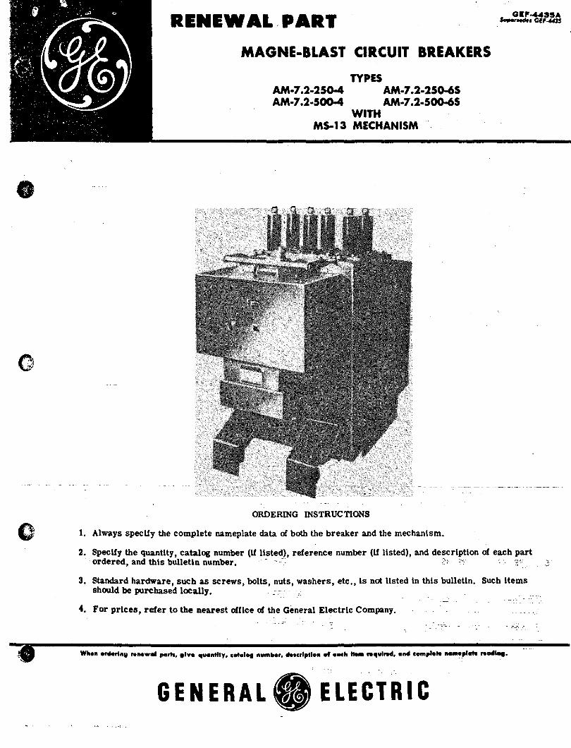
RENEWAL PART
MAGNE-BLAST CIRCUIT BREAKERS
AM·7.2·250-4 AM·7.2·500-4
TYPES AM·7.2·250-65 AM·7.2·500-65
WITH M5-13 MECHANISM
ORDERING INSTRUCTIONS o 1. Always specify the complete nameplate data of both the breaker and the mechanism.
2. Specify the quantity, catalog number (if listed), reference number (if listed), and description of each part - ordered, and this bulletln number. - ?~ C:: '.~. ,'.:,.
3. Standard hardware, such as screws, bolts, nuts, washers, etc., is not Hsted in this bulletin. Such items should be purchased locally. . :::: ,. .
4. For prices, refer to the nearest office of the General Electric Company.
GENERAL. ELECTRIC
,GEF-4435A
16
13
2
TYPE AM·7.2 MAGNE·BLAST CIRCUIT BREAKERS
(1200 Amp.)
1-----------9
11---#------ 6
15
7 4
5
18
19
A. Breaker, Type AM-7. 2-4
~ -- -- I - -
0tiT 22 I. Barrier suppcMt
25
31 (((fE~~~~~~_26
32 33 /
27
(2000 Amps)
C. Hinge assembly (see Section A-A)
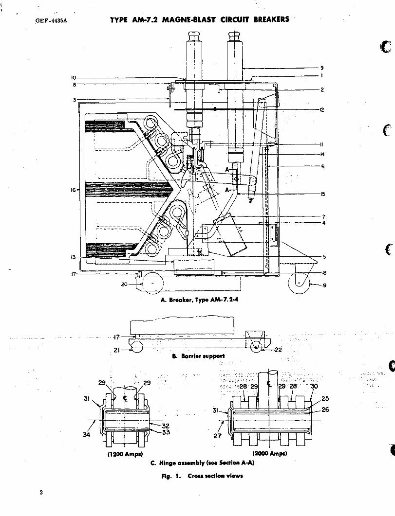
Fig. 1. Crosa sectloa views
(
)

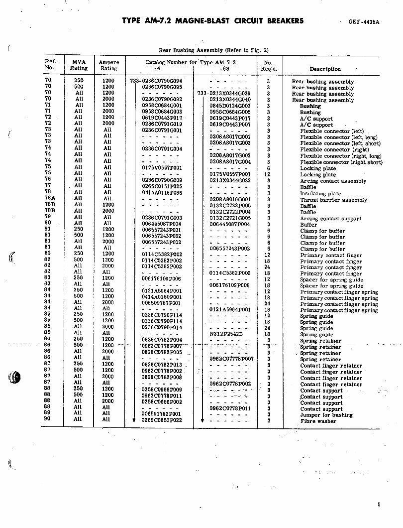
TYPE AM·7.2 MAGNE·BLAST CIRCUIT BREAKERS , .GEF-4435A
Type AM-7. 2 Breaker (Refer to Fig. 1)
Ref. Catalog Number for Type AM-7. 2 No. No. MVA Amps Type -4 -6S Req'd. Description
1 All 2000 All 733-0258C0680PIO 733-0258C0680PI0 1 Top plate 2 All 2000 All 0958 C0682 P009 0958C0682P009 1 Angle 3 All All All 0265C0151 P028 0265C0151 P028 3 Box barrier clip 4 All All All 0836C0180P012 - - - - - - 3 Arc chute support (right) 4 All All All 0836C0180P013 - - - - - - 3 Arc chute support (left) 4 All All All - - - - - - 0836C0180P014 6 Ar c chute support 5 All All All 0258C0619G012 0258C0619G012 3 Arc chute clamp 6 All All All 0802B0764GOOI 0802B0764GOOI 3 Vertical barrier 7 All All All 0236B0292P002 0236 B0292 P002 3 Booster cylinder 8 All All All 0265C0151P030 0265C0151 P030 ** Shim
e
9 All 1200 All 0845D0123G003 0845D0123G003 3 Bushing, long 9 All 2000 All 0958C0683G003 0958C0683G003 3 Bushing, long
10 All All All 0958 C0628 POO 5 0958C0628P005 ** Shim, 0.004 in. thick 10 All All All 0958C0628P006 0958 C06 28 P006 ** Shim, 0.010 in. thick 11 250 1200 A. H 0688 C0586 P020 - - - - - - 6 Horizontal barrier (lower) 11 500 1200 A. H 0688C0586P021 - - - - - - 6 Horizontal barrier (lower) 11 All 1200 All - - - - - - 0132C2738 P004 6 Horizontal barrier (lower) 11 All 2000 All 0688C0586P013 ,0132C2738P005 6 Horizontal barrier (lower I 12 All 1200 All 0137A6047G003 - - - - - - 3 Horizontal barrier (upper) 12 All 1200 All - - - - - - 0258C0614P031 6 Horizontal barrier (upper I 12 All 2000 All 0137A6047G005 - - - - - - 3 Horizontal barrier (upper) . 12 All 2000 All - - - - - - 0258C0614P032 6 Horizontal barrier (upperJ 13 All All All 0265C0162P017 0265C0162P017 2 Side ,barrier 14 I All All All 0281B0708GOOI 0281 B0708GOOI 3 I Operating rod assembly 15 All All All 0688C0589P017 0688C0589P017 3 i Connection bar 16 I 250 All All 0265C0176G002 - - - - - - 3 Box barrier assembly 16 I 500 All All 0265C0176GOOI - - - - - - 3 Box barrier assembly 16 All All All - - - - - - 0265C0176G005 3 Box barrier assembly 17 All All All 0107B9348P007 0107B9348P007 1 Box barrier support 17 <3 0 0 01 07B9348 P005 0107B9348P005 1 Box barrier support 18 All All
I
All 0107B9348P002 0107B9348P002 1 Box barrier support 19 All All All 0456A0862P008 0456A0862P008 2 Front wheel and caster 20 All All All 0456A0862POOI 0456A0862POOI 2 Wheel and spanner bushing 21 <3 0 0 006597296P007 006597296P007 2 Wheel 22 <3 (5 <3 0236C0768G007 0236 C0768G007 2 Front wheel and caster
*23 All 2000 All 0898B0282G007 0898B0282G007 3 Hinge point assembly *23 All 2000 RA, RH 0898B0282G002 0898B0282G002 3 Hinge point assembly *24 All 1200 _.AJ_ H -- 0898B0282G006 -- - --.- 0898B0282G006 3 _ Hinge _po in! _~_f!~mbly .- . .-
- 0898B028-2GOOI 0a98B028-2GOoi - . 3----*24 All 1200 RA, RH Hinge point assembly 25 All 2000 All- 006442257POOI 006442257POOI .. 3 Bearing 26 All 2000 All 0369A0407POOI 0369A040'7POoi 3 Spring
,
27 All 2000 All 0414AOI06P007 0414AOI06P007 3 Bolt 28 All 2000 All 006442246POOI 0064422~POOl 6- ,. Spacer 29 All All A,H Ol04A2495POOl 0104A2495pOOl 6 Hinge washer 29 All All· .
.-
RA, RH 0456A0884POOl 0456A0884POOI r-~~~ Hinge washer
::.. 30 All 2000 All 006441630POOl 006441620POoo .' Washer ..
31 All All ,006441617POOl 0064416f'lPOOI .... . Wasner, _ , . _ ' ,. All ..
32 All 1200 A, H._ 0137A9186POOl 0137A9fUPOOr 3 Bearing , 33 All 1200 A,H 0421A0239POOI 0421A0239FOOI 3 Spring 34 All 1200 A,H 0414AOI 06 P004 0414AOI06P004 3 Bearing screw
<3 Breaker model list with ·W" suffix. ** As required. - -
• This assembly includes parts 25 to 34 inclusive.
. ;
3

CEF-4435A
71---
72----I!!!I
81---
74---
75---
77---
78----
A. Rearvlew
4
TYPE AM·7.2 MAGNE-BLAST CIRCUIT BREAKERS
2::· ... ..
I. Side view
88
87
85
84
83
2
81 80
Fig. 2. Rear bushing assembly (Ref. No. 70)
'0 •
78A
~--71 "
~--88
1----87
~--85
::.1---- 84 .~_
~---83
---82
c .. Front view
(
{
«
r(j
Ref. No.
70 70 70 70 71 71 72 72 73 73 73 74 74 74 75 75 76 77 78 78A 78B 78B 79 80 81 81 81 81 82 82 82 82 83 83 84 84 84 84 85 85 85 85 86 86 86 86 87 87 87 87 88 88 88 88 89 90
MVA Ampere Rating Rating
250 1200 500 1200 All 1200 All 2000 All 1200 All 2000 All 1200 All 2000 All All All All All All All All All All All All All All All All All All All All All All All All All 1200 All 2000 All All All All 250 1200 500 1200 All 2000 All All 250 1200 500 I 1200 All 2000 All i All 250 I 1200 All All 250 I 1200 500 ! 1200
I,' All i 2000 All , All I 250 i 1200
I 500 " 1200
I iliJt~~-All 2000 All All 250 1200 500 1200 All 2000 All All 250 1200 500 1200 All 2000 All All All All All All
TYPE AM·7.2 MAGNE-BLAST CIRCUIT BREAKERS GEF-4435A
Rear Bushing Assembly (Refer to Fig. 2)
Catalog Number for Type AM-7. 2 -4 -6S
733-0236C0790G094 0236C0790G095
0236C0790G092 0958C0684GOOI 0958 C0684G003 0619C0443P017 0236C0791G019 0236 C0791 GOOI
0236 C0791 G004
0175V0557POOI
0236 C0790G009 0265C0151P025 0414A01l6P086
0236 C079l G003 006445087P004 006557243POOI 006557243P002 006557243P002
Ct114C5382P002 01l4C5382P002 01l4C5382P002
006176l09P006
0121A5964POOI 0414A0180POOI 006509787POOI
0236 C0790P114 0236 C0790Pl14 0236C0790P014
0828C0782P004 0962 C0778P007' 0828C0782P005
0828C0782P013 0962C0778P002 0828 C0782POoil
• 0258C0666P009 0962C0778POll 0258C0666P002
006591783POOI 0269C0853P022
733-0213X0344OO39 0213X0344OO40 0845001240003 0958C0684OO05 0619C0443P017 0619C0443P007
0208A8017OOOl 0208A80l7OO03
0208A80l7OO02 0208A80l7OO04
Ol75V0557POOl 0213X0344OO32
0208A80l6OOOl 0132C2722P005 0132C2722P004 Ol32C272lOO05 006445087P004
006557243P002
0114C5382P002
006176l09P006
Ol21A5964POOl
N312P2542B
0962CO'1778P007
0962C0778P002 --:~.-.- ,.- .-. -
0962C0778POl1
No. Req'd.
3 3 3 3 3 3 3 3 3 3 3 3 3 3 6
12 3 3 3 3 3 3 3 3 6 6 6 6
12 18 24 18 12 18 12 18 24 18 12 18 24 18
3 ~'
3 3 3 3 3 3 3 3 3 3 3 3
Description
Rear bushing assembly Rear bushing assembly Rear bUShing assembly Rear bushing assembly
Busbing Busbing A/C support A/c support Flexible connector (left) Flexible connector (left, long) Flexible connector (left, short) Flexible connector (right) Flexible connector (right, long) Flexible connector (right, short) Locking plate Locking plate Arcing contact assembly Baffle Insulating plate Throat barrier assembly Baffle Baffle Arcing contact support Buffer Clamp for buffer Clamp for buffer Clamp for buffer Clamp for buffer Primary contact finger Primary contact finger Primary contact finger
"Primary contact finger Spacer for spring guide Spacer for spring guide Primary contact finger spring Primary contact finger spring Primary contact finger spring Primary contact finger spring Spring guide Spring guide Spring guide Spring guide Spring retainer
: --sprfug ·retiiiii~r -- --," Spring retainer
Spring retainer Contact finger retainer Contact finger retainer Contact finger retainer Contact finger retainer Contact support ,Conlact support . Contact support Contact support Jumper for bushing Fibre washer
5

GEF-4435A TYPE AM-7.2 MAGNE-8LAST CIRCUIT BREAKERS
129 __ ......:':iG 131
113---
120 171
172 __ ----: 176
108---
105---
134 124
127 ______ -L-_-' 130
136 134 132
107
167
106 103
128 135
176
A. Complete arc chute assembly (Ref. No.1 00)
157 153 140 160 136 132
152, 21
137 164 158 156 143 169
165 142
168 154 117 145 163
167
155 144
162 17 118
119
174 '
175 147 167
C. Component parts
Fig. 3. Ar-c chute
6
.----139
126 133
106 106
156'
169 114;ii6 113 illS
142
161
109 !It 150
151 173
128
103
B. Front view
D. Complete arc chute assembly (different pole pie<es and braces)
«
«,~
(( "
(
TYPE AM-7.2 MAGNE-BLAST CIRCUIT BREAKERS
:17------0
'01--
116E .II6F
__ ~116C 1160
IIA 118 IIC
1110
"'E iliF
·~~--·-I03
'--___ 128 135
E. Complete arc chute assembly ("-65" design)
123---
G. Front view ("-65" design)
Fig. 3. Arc chute (cont'd.)
f. 5ide cover removed ("-65" design)
GEF-4435A
178
7
GEF-4435A TYPE AM-7.2 MAGNE-BLAST CIRCUIT BREAKERS
ARC CHUTE ASSEMBLY (Refer to Fig. :3
Ref. Cat. N'J. fur Type A:-'l- i. 2 No. :-';0. -4 I -68 Req'd. Description
100 733-0213X0215GOO9 73::- 0213X0215GO 12 3 Arc chutEo assembly complete 101 0264BOI0OG014 1 0264BIOOG017 3 Arc chutEo sides 102
I 0265C0150POO2 i 0132C2721POOl 3 t'pper 5u;;,?ort
103 0258C0615P015 I 0132C2721G002 3 Lower s\:?port
104 0265C0161POO6
I 0265C0161 P006 6 L,)wer br'ace
,.105 0114C5495GOO2 01l4C5495GOO3 3 Rear brace ~.} 06 0114C5495GOO4
I 0114C5495GOO4 3 Side brac,=,
107 ' 0962C0750P--6 ------ 6 Shield ~'108 0962C0701G004 ------ 3 Lower pc.:e pieces, left ~109 0962C0701GOO5 ------ 3 Lower pc.:e pieces, right ~110 0114C5304GOO4 ------ 3 u)wer po:e pieces, left .:" III Ol14C5304GOO5 ------ 3 Lower po:e pieces, right
lIlA ------ 0132A2736G007 3 Lower po:e pieces, left lIlB ------ 0132A2736GOO8 3 Lower pole pieces, right 111C ------ O132A2736G009 3 Lower po:e pieces, left 1110 ------ 0132A2736G010 3 Lower po;e pi~ces, left l11E ------ O132A2736GOll 3 Lower po:e pieces, left I11F ------ 0132A2736G012 3 Lower pcle pieces, right
:112 0108B1943POOl 0132C2738POOI 6 Side brace 113 0962C0701GOO2 ------ 3 l'pper pole pieces, left 114 0962C0701GOO3
I ------ 3 l'pper poi.., pieces, right
115 01l4C5304GOO2 ------ 3 l'pper pol.., pieces, left 116 I 0114C5304G003
I ------ 3 J:pper po:.., pieces, right
l16A ----- .. 0132C2736G001 3 l'pper po;'" pieces, left 116B ------ I O132C2736GOO2 3 l'pper po;e pieces, right 116C ------ I 0132C2736G003 3 t'pper po:", pieces, left 1160 ------
I 0132C2736G004 3 l'pper pole pieces, right
l16E ------ 0132C2736GOO5 3 l'pper pole pieces, left 116F ------ 0132C2736G006 3 l'pper pole pieces, right 117 0108B1943POO2 0132C2738P002 6 Rear brac,=, 118 0688C0589P013
I ------ 18 Core
118 ------ 0258C0615P019 3 Core, 2 1: '16 in. ---.---
I !18 ------ 0258C0615P035 3 Core, 3 3 16 in. 119 0688C0589P014 ------ 18 Core ins~ating tube :19 ------ ! 0258C0616P023 3 Core insl:~ating tube for 2 Il/16-in. 119 ------ 0258C0616P026 3 Core ins1:.:..ating tube for 3 3/16-in. 120 006445050PO 1 0 006445050POI0 3 Spacer 121 0619C0400P017 ------ 3 Soacer 122 0962C0750POIO 0962C0750POI0 3 .l,.'/C suppc..rt, right 123 0962C0750POO9 0962C0750POO9 3 A IC suppert, left 124 0414A0102POO8 0414AOI02P008 3 Stud 126 0421A0209P082 0421A0209P082 6 Spacer 127 0061676109p070 ------ 12 Spacer 128 0421A0208P093 . 0421A0208P093 12 . Sp'acer (7 a in.)
"129 0619C0494P009 0619C0494P009 # Shim 130 006442389POO3 006176109P070 6 Spacer (5 32 in. )
"131 006442389POO4 ------ 6 Spacer 132 0456AOB88POO6 0456A0888 POG6 6 Spacer 133 0688C0589P018, ------ 6 Spacer :"34 0137A9163POO2 0137 A9163P002 18 Bushing 135 006176109P089 006176109P089 3 Spacer (3 4 in. ) 136 0421A0208P497 0421A0208P497 6 Spacer (I 1 '2 in. ) 137 0265C0150P015 0265C0150POl5 6 Spacer 138 0962C0750POO3 Q962C0750P003 3 Block 139 0962C0750POO2 0962C0750P002 3 Dust shield 140 0265C0163POO8 0265C0163POO8 6 l'pper coil support HI 0265C0163POO2 J265C0163P009 6 Barrier 142 0414A0194POO2 ------ 6 !.fycalex, upper shield 143 0414A0196POOI 1J414A0196POOl 6 Spacer 144 0265C0150POl3 0265C0150P013 6 Spacer 145 0414A0196POO2 0414A0196P002 6 Spacer 146 0962C0750POO7 0962C0750POO7 3 Spacer
o ?efer to Fig. 3A and 3D to determi::e proper arrangement for side brace, rear brace, and p:iJe pieces. = .-\s required • ~ot illustrated
8
core core
,.
Cl

TYPE AM-7.2 MAGNE-BLAST CIRCUIT BREAKERS GEF-4435A
ARC CHUTE ASSEMBLY (Refer to Fig. 3 ICont'd)
Ref. Cat. r-;(J. for Type AM-7. 2 No. No. -4 -6S Req'd. Description
147 733- 0619C0489Por":. 733-0619C0489POO5 3
I Lower coil support, left
148 0619C0489PO( 4) 0132C2745POI0 3 Lower coil support, right 149 0414A0198P001 0132C2745POll 3 Insulation seal 150 0258C0616POll 0258C0616POll 3 I Spacer 151 0265COI5OGO(>6 0132C2746G002 3 Runner 152 0619C 0400G 00 1 0132C2728GOI 3 Coil, upper 153 0265C0155GOO3 ------ 6 Coil, upper 153 ------ 0265C0155G003 3 Coil, upper 153 ------ 0265C0155G009 3 Coil, upper 154 0265C0155G008 0269C0878G002 3 Coil, lower 155 0265C0155GOC-S 0265C0155G006 6 Coil. lower 156 0414A0116PO(;2 0108B5520POOI 3 Insulation plate 157 0414A0197POGl 0414A0197POOI 3 Shim 158 0414A0197P002 0414AO 197 P002 3 Shim 159 0265C0154GOO3 0265C0154GOO3 3 Runner assembly 160 0265C0154GOO5 013 2C 2708 P009 6 Runner assembly 161 0265C0154GOO 1 0132C2746GOOI 3 Runner assembly 162 0265COI54GOC" 0265C0154G009 3 Runner assembly 163 0456A0888POO3 0456A0888POO3 9 Spacer (3/4 in. long) 164 0421A0208P022 0421A0208P022 12 Spacer (21/32 in. long) 165 0421A0208POl '7 0421A020ap017 24 Spacer (17/32 in . .long) 166 006176109POO'; 006176 ~09PO_06 36 Spacer (5/32 in. long) 167 0456A0336POOI 0456A0891P210 6 Lower runner parrier 168 0456A0891P210 0456A0891P020 3 Sleeve 169 0688C0512GOO3 0132C2708G002 3 Runner 170 0265C0161P017 0265C0161P017 3 Spacer 171 0414AOI31POC'..f 0414A0131POO4 # Spacer
*172 0456A0891P2('~ 0456A0891 P208 # Shim 173 006176109P09..f ------ 6 Spacer J74 0421A0201POO1 0421A0201POOI 6 Lower runner shield 175 0802B0735POO 1 0802B0735P004 6 Lower runner insulation
*176 0456A0891PIC3 ------ # Shim 13/16 in. thick)
177 0108BI943PO('3 ------ 6 Spacer 178 ------ 0132C2737GOO3 3 Shield and cooler assembly, right
178 ------ 0132C2737GOO4 3 Shield and cooler assembly, left
"Not illustrated
9

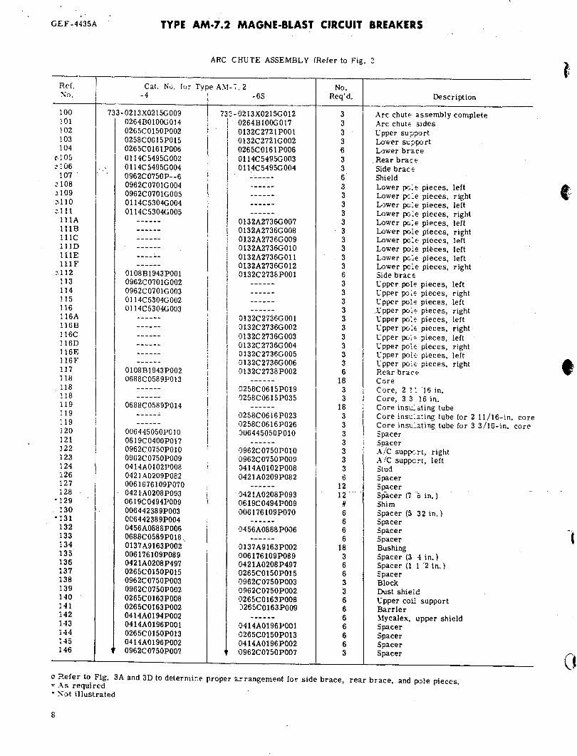
GEF -4435A TYPE AM·7.2 MAGNE·BLAST CIRCUIT BREAKERS
214
A. 2000 amp, all MV A ratings B. 1200 amp, 500H and SOOA C. 1200 amp, 150H, 250H, 150A, 250A MVA ratings MVA ratings
Fig. 4. Movable contact arm assembly (Ref. No. 210)
Movable Contact Arm Assembly Refer to Lg. 4)
Ref. Catalog Number for Type AM-7. 2 ~o.
No. MVA Amps -4 -65 Re,,'d. Description
210 250 120C 733-0236C0792G096 733-0213X0343C~64 3 Movable contact arm assembly 210 500 120C 0236C0792G099 0213X0343G064 3 Movable contact arm asse::nbly 210 250 200e 0236 C0972G091 0213X0343v)65 3 Movable contact arm assembly 210 500 200e 02 36C0972Gl 01 0213X0343G065 3 Movable contact arm assembly 211 250 All 00 02B07 42G003 0108B5536GOOI 3 Movable arcing contact 211 500 All 0002B0742G004 0108B5536GOOI 3 Movable arcing contact 212 250 1200 0137A9164P003 - - - - - - 3 Movable primary contact 212 500 120(, 01 14C5382P004 - - - - - - € Movable primary contact 212 All 120C - - - - - - 0114C5382P004 5 Movable primary contact 212 All 200C 0137A9164P003 0114C5382P004 5 I Movable primary contact 213 250 1200 0137A9164P004 - - - - - - 3 Movable primary contact 213 All 200e 0137A9164P001 0114C5382P004 3 Movable primary contact 214 All All 0258C0666P007 0258C0666P007 6 Contact arm 215 250 1200 ' 0236C0792GQ31' 0213X0343G094 ., 3 Tube and pisto_n assembl)' 215 500 1200 0236C0792G015 0213X0343G094 ,. ~ - ," 3 Tube and piston assembly 215 All 2000 0236C0792G015 0213X0343G094 3 Tube and piston assembly 216 All 2000 0258C0666P006 0258C0666P006 € Contact arm ' 217 All All 0';21A0248POOI 0421A0248 POOl , .. 3 Piston ring , 218 All All 0'; 56A0874P003 0456A0874P003 3 Piston ring expander (corrugated) 218A 250 120C' 0.; 56A0874P002 - - - - - - 3 Piston ring equalizer (smooth) 218A 500 1200 0.; 56A0874P002 - - - - - - " 3 PistQIJ. ring equalizer (smooth) 218A All 2000 0.; 56A087 4P002
~ ~; ; '~'€
,'t'-. ~ i
''pisfcin''riiig equalizer (smooth) - - - - - -218A All All - - - - - - 0456A08 7 4 P002 € Piston ring equalizer (smooth) 219 All All 0414A0146P054 0414A0146P054 12 Flex nut (1/2-13) . 220 All All 0414A0146P053 0414A0146 P053 ~ Flex nut (3/8-16)
·221 500 1200 0258C0619P002 '6 -,. Spacer
.. - - - - - -1
*Not required with mo\'at,e primary contact Cat. No. 01l4C5382P004. . . -- --. -- - >_.
-. ~:: r -.
10
•
•
•
TYPE AM·7.2 MAGNE·BLAST CIRCUIT BREAKERS GEF -4~.35A
268
269
271
264 263A 261 276 262 274
265 263 263A 275 310 277 312 278 266 279
280 267
A. Cross section view, MS-13 mechanism 282 258
B. Opening spring assembly
293
Ref. No.
250 251 252 253 253A 254 255 256 257
VIEW A
299 292
VIEW 0
Cat. No.
733-006443518POOl 0836C0190P003 0258C0608P007 0215D047OG058 0215D047OG060 0215D047OG055 006551742POOI 0258C0604P008 0137 A9088POOI
287 ___ --,
VIEW E
288
287------t 286
VIEW B
2~ ---1i7+r-296 ~~~~
307
C. Detailed view, MS-13 mechanism
Fig~~.s:. 'Ms..13 mechanism
MS-13. Mechanism (Refer to F:g. 5)
. No, Per ~echanism
Shaft
289
253A
Description
1 4 1 1 1 1 1
Crank, phase 1 and 3 Latch
1 1
Crank, phase 2 Cra~, phase 2 Link Spring Spring clip Veeder counter
VIEW C
VIEW G
11
\
.'
GEF-4435A TYPE AM-7.2 MAGNE-BLAST CIRCUIT BREAKERS
MS-13 Mechanism {Rder to L~. 5 (cont'd) 0 Ref No. Per
I I I
D3scription No. Cat. No. Mecha~.ism , ~
258 733 - 0215OO470G057 Link 259 0281B0711G001 Indicator assembly 260 0258C0609P001 Prop 261 006375521G004 Closing coil (110v d-c) 250A and 250H 261 0802B0799GOOl Closing coil (125v d-c, 230v a-c 250A a~.d 250H 261 0802B0799G003 1 Closing coil (250v d-c) 250A and 250H 261 006375522G002 1 Closing coil (25Ov d-c) 500H 261 006375522GOOl 1 Closing coil (125v d-c, 230v a-ci 500H
CO, 261 006375522G004 1 Closing coil (125v d-c, 230v a-ci 500A 261 006375522G003 1 Closing coil (125v d-cl 500A 262 0236C0796P006 1 Plunger, 500A and 500H 262 0236C0796P006 1 Plunger, 500A, 500H 264 0962C0700G002 1 Pole piece, 250A, 250H 264 0962C0700G012 1 Pole piece, 500A, 500H 265 A Buffer 266 0236C0796G002 1 Armature plate 267 0236C0796P028 2 Stud, 250A and 250H 267 0236C0796P008 2 Stud, 500A and 500H 268 0137 A6086P022 1 Pin 269 0258C0630P007 1 Clevis 270 0258C0630P031 Plate 271 0258C0630P008 Rod 272 0414A0109P008 1 Buffer 273 0258C0630GOO 1 1 Complete spring assembly 274 0456A0808 1 Inner spring 275 0456A0807 Outer spring 276 0258C0630P003 Spring retainer 277 0258C0630P005 Retaining plate
t 278 0258C0630G004 Spring base 279 0137A6087P020 Pin 280 0258C0630P002 Bracket 281 0258C0611POOl Latch shaft (250H and 500H) 281 0258C0611P002 1 Latch shaft (250A and 500A) 282 0258C0611 POll 1 Stop bar 283 0121A7436GOOl 2 Latch shaft bearing 284 0421A0256 Spring 285 0258C0609P004 Crank 286 0215D047OG053 Roller 287 0215004 70G05 2 2 Link 288 0258C0611 P003 1 Prop pin 289 0414AOllOPOOl 1 Pin 290 04l4A01l2P001 1 Trip roller bearing 291 - 0456A0876PI03 2 Spacer 292 006509799 2 Spring 293 0414AOllOPOO3 1 Pin 294 006477097 1 Prop spring 295 0258C0609P008 1 Trip roller pin
..) 296 0104A2474POOl 1 Pin 299 0421A0210POOl 2 Spacer 301 '. 0258C0608P003
.- .. 1 Latch guide 302 .' 0258C0611P005 1 Pin 303 0958C0657P004 1 Pin 304 0421A0209P101 2 Spacer 305 0258C0609POO6 1 Roller 306 0137 A6086P039 1 Pin 307 0421A0208P143 2 Spacer 308 0619C0478P019 3 Pin 309 006442239POOl 2 Bearing, 250A and 250H 309 006442239P003 2 Dearing, 500A and 500H 310 0236C0796P026 1 Armature
*311 0258C0611P015 1 Cover for opening spring,. 250Aand 500A
(! 312 0236C0795P075 1. Adjusting screw
QOrder 0414AOI09P010 for 2-1/2 inch O. D. buffer Order 0414AOI09P012 for 3-3/4 inch O. D. buffer
• Not illustrated.. '.'
12

)
TYPE AM-7.2 MAGNE-BLAST CIRCUIT BREAKERS GEF -4435A
325 325
327 327 326 Ref. 1 Nu, No. Cat. No. Reqc, Description
328
-~ /_. I Iatprluck plun~er.
324 733-0236C078 7GOD 1 1 complete
329 , I
-ij-~_ 332
325 0236C 078 7 PO 12 1 Plunger 326 0236C0787G002 i 1 Bracket 327 006509728POO 1 I 1 Spring 328 ·0137A6085P022 2 Pin 329 0236C0787PO 14 i 1 Roller 330 0236C0787P005 I 1 Pin 331 0236C0787P016 J 2 Crank 332 0958t0697P003 1 Crank
.V/EW- A-A Fig. 6. Interlock plunger for MS-13 mechanism
A. Right side view 8. Front view C. Left side view
Ref. No. Cat. No.
350 733-0258C0604G003 351 0258C0604P002 352 0236C0795P040 352 -- -
0236C0795P041 353 0174V0394P003 353 0174V0394P004 354 006445059 356 ti 358 0456A0876P004 359 0236C0788G050 360 0137A9128 362 0258C0601G003 363 0236C0788G052
*364 0236C0788P008 365 - 0236C0788G054 367 023.6C0788P034 369 04 56A0866 POO 1
-369 0456A0866POOl *370 0456A0866P002
371 006174582GOOl 371 006174582G002 371 006174582G032 371 0062750700001 371 0062750700002 372 0215D0470G005
• Not ilbstrated . .lRefer ::> breaker for proper model.
Fig. 7. MS-13 mechanism
\15-13 :\!~('hanism (Refer to Fig. 7)
No. Per ivlecha01i Sf" De~c;-iption
1 :o.lanual trip r :,d 1 :'!anual trip !"':>d suppo:-: 1 Roc!. 250A p-.d _250H 1 Rod. 500A and 500H 1 Tube. 250A and 250H 1 Tube~ 500A and 500H 1 Insulating tube 1 Auxiliary switch 2 Spacer . -1 Interlock prop assembly 1 Spring 1 Bearing.bra.<:,ket 1 Roller ancili:-J;; assembly 2 Link 1 Roller asser.lo1y 1 Bracket 1 Interlock S\\'itch 1 Latch check s",-itch. when used 1 Cut-off switch. 250A a:-:d 50DA 1 Potential trip coil (125\- d-c) 1 Potential trip coil (25th- d-c) 1 Potential trip coil (23th- a-c) 1 Potential trip coil (24\- d-c) 1 Potential tri p coil (48y d-c) 1 Potential trip linkage
Type 5B~ - Order Cat. No. 0137A9192G003. Type 5B-12 - Order Cat. No. 013iA9192GOll. 13

GEF-4435A TYPE AM-7.2 MAGNE-BLAST CIRCUIT BREAKERS
503 505 512
507
500
510
Rg. 8. Secondary disconnecting device (Ref. No. 500) Fig. 9. Maintenance closing device (Ref. No. 510)
Secondary DisconnECt DevicE and Mainle~nce Closing Device (Refer to Figs. 8 and 9)
~o. PE:- No. Per R~f. ~fechani5::::l Mechanism ~:J. Cat. No. 250H, 50C-i 250A,500A D€ scription
~·OO 733-0802B0795GOO5 1 - Secondary disconnect device, complete, 16 points -500 0264BOI73GOO5 - 2 Secondary disconnect device, complete, 7 points
503 006319964P002 16 14 Contact plug ~05 0OO848768POOI 16 14 Lockwasher for cor-tact plug 507 006505244POOI 1 - Contact socket, 16 point
-507 006048758POOl, - - - 2 Contact socket, 7 P'.)int 510 0258C0669GOOI 1 1 Maintenance closing device 512 0366A0234POOI t t Contact nut for No. 8 wire ~12 0366A0234P002 t t Contact nut for No. 14 wire ~12 0366A0234 POO3 t t Contact nut for No. 12 wire
-,-.-
-. ".':' r -. ." ::' :;. ~_... _
* ~ot illustrated. .' 'i" , " . " _ . "." ,
t A total of 16 contact nuts is used on the 250H a.nd 500H breakers and a total of 14 contact nUts is used on the ·250A and 500A '::lreakers. Order size and 'quantity of contact ::uts to correspond with the size and quantity of wires entering the secondary disconnect device, .
GE f -443SA
1 1 2 2 2 2 2 2 2 2 2 2 2 2 3 3 3 3 3 3 4 4 4 4 4 .; 4 4 4 4 4
.is
.is
.is
.).S
.is
.loS
.1S
.lo5
.).S
.).5 ~7
.:17
.:17
.:17
.:1'7 .:!11 ~11
~11
:2 .=.12 .loI3 .=.13 .113
.113
Ref. )1;0,
7 14 73 .3 73 74 74 74 76 78 84 84 84 84
142 156 167 174 178 178 211 211 212 212 212 212 213 213 215 215 215 261 261 261 261 261 261 261 261 261 261 371 371 371 371 371 663 663 663 738 738 753 753 753
753
MVA AMPS
ALL ALL ALL ALL ALL ALL ALL ALL ALL ALL 250 500 ALL ALL ALL ALL ALL ALL ALL ALL 250 500 250 500 ALL ALL i 250 ALL 250 500 ALL 250 250 250 250 500H 500H 500H 500H 500A 500A ALL 'ALL ALL ALL ALL ALL ALL ALL ALL ALL ALL ALL ALL
ALL
ALL ALL ALL ALL ALL ALL ALL ALL ALL ALL 1200 1200 2000 ALL ALL ALL ALL ALL ALL ALL ALL ALL 1200 1200 1200 2000 1200 2000 1200 1200 2000 ALL ALL ALL ALL ALL ALL ALL ALL ALL ALL ALL ACL ALL ALL ALL ALL ALL ALL ALL ALL ALL ALL ALL
ALL
TYPE AM-7.2 MAGNE-BLAST CIRCUIT BREAKERS
PARTS ~ECOMl\IENDED FOR :-iOR~lAL S,OCK
Ca:.;,Jo~ NU[;.::.er for Type AM-7. 2 -4 -65
733-02~2B0292P~02
022 j B0708GV01 022 -::C0791GO(JI
022 ::C079OG009 0414.A0116POc 6 0121AS964PCr01 0414.-\0180PO'='1 OOE ,)09787PO(: 1
0414AO 194P002 0414A0116P002 045-3A0336P001 042: A0201P001
08C 2B0742GCC3 08C 2B0742G004 013 -:- A9164P003 011.;.cS382POC'4
012: A9164POC3 012-:-A9164PV.,; Ql:3 -:- A9164P004 023 :'C0792G021 023 -3C 0792GO 15 022 :C0792G015 OOE:: 7 5521G(IC'; 08C2B0799GOfil 00E375521GC'C'3 08C 2B0799GOC'3 OOE 375522GOC:5 OOE 275522GOC2 OOE 2i5522GOC'5 OOE 2-;"5522GOCI OOE 3i5522GOC4 OOE 275522GOC3 OOE: i4582GOCI OOE : 7 45-S2GOC'2-OOE} 74582G032 00627507OGOOI 00627507OGO(,2 006275017G019 00E:i5017G033 0062i5017G020 OOE: 74599(;002 006: 74599GOC-€ 006275017GOl9 0062i5017G020 0062i5017G033
006:?-;"5017G034
733-0263B0292P002 0281 B07 08G 00 1
0208A8017GOOI 0208A8017G003
0208A8017G002 0208A8017G004 02i3X0344G032
0121A5964POOI
0414A0197POOI 0132C2735P007 0421A0201POOI 0132C2737G003 0132C2737G004 0108B5536GOOl 0108BS536G001
0114C5382P004 o 114C 538 2P004
0114C5382P004 0213X0343G094 0213X0343G094 0213X0343G094 006375521G004 0802B0799GOOI 006375521G003 0802B0799G003 006375522G005 006375522G002 006375522G005 006375522GOOI 006375522GOC4 006375522G003 006174582GOOI 00Sf74582G002 006174582G032 00627507OGOOI 00627507OG002
. 006275017G019 006275017G033
". 006275017G020 006174599G002 006174599G006 006275017G019 006275017G020 006275017G033
006275017G034
I ! I No; I I Req d"
3 3 3 3 3 3 3 3 3 3
12 18 24 18 6 3 6 6 3 3 3 3 3 6 6 6 3 3 3 3 3 1 1 1 1
'. 1
1 1 1 1 1 1 1 1 1 1 1 1 1 3 1 1 1 1
Desc ription
3~oster cylinder ':;perating -ud assembly ?lexible c :..nnectol' (left) :;exible c :..:.nector (left. long) ?";exible c :·nnector (left, short) ?"lexible c:.nnector (right) :lexible c :..nnector (right. long) ;'"lexible c:..nnector (right. short) .!O rcing co~. :act assembly i~.sulating plate ?rin',ary CJntact finger spring ?:-imary c:,ntact finger spring ?:-imary c :!ntact finger spring ?:-imary c :.ntact finger spring t:oper shi<:ld (Mycalex) i~. sulation ,plate '~··Jwer rur.~er barrier :"':,wer ru:-,::~, shield ~:-:ield anc cooler assembly. right ~:-jeld and cooler assembly, left
~ ~.:c)Vable a:-cing contact ; :.:Jvable a:-cing contact : ~.:)Vable p:-imary contact : :.:Jvable D:-imary contact ; '.:")vable p::-:mary contact ; ~':'J\'able f:·:rimary contact i ~.: )\'able ~ ::-imary contact ~.:0vable p:-imary contact
i :ube and ;:ston assembly : ;'Jbe and ;iston assembly i :-.Jbe and ;.;ston assembly : Cosing c0:1 (HOv d-c) : Closing c·:·:1 (125v d-c or 230v a-c, 60 hz) i ClOSing ce·:l (220v d-c) :C:osing c::: (250v d-c) 'Closing c::.l (llOv d-c) ! Cosing c.::1 (125v d-c and 230v a-c. 60hz) : Closing cc:l (220v d-c) : Closing c·::'1 (250v d-c) . Cosing c::] (125v d-c or 230v a-c) I Cosing eel (250v d-c) [ P::>te:1tial trip coil (J25v d-.c) I ?Jtential ,:rip coil (250v d-c) i F )tential t rip coil (230v a-c. hz) i P )tential : :-ip coil (24v d-c) I F·)tential ,::-ip coil (48v d-c) ! l'~dervo1ta.;::e device coil (125v d-cl
i
l' l' :1dervo.ltaf:e. device .. c . .o. il. (230v a-.c, hz) r:1dervo1tg~ device~coiU2S0~d-c). . Current: tr)pcoil(3)lmp, 60hz) Capacitor trip coil (23Ov a-c, 60hz) C .:mt rol dence Cc)il (125v d-c) C 'Jntrol de.ice coil (250v d-c) C )ntrol de>1ce coil
I 230v a-c. :60hz continuous) I C :.ntrol de,ice coil . ' .... _. i 230v a-c :60h·z. intermittent)
.1 Refer to nameplate or summary fc:::- proper -;oltage rating.
(
(
( \.
(
)
)
-.
TYPE AM-7.2 MAGNE-BLAST CIRCUIT BREAKERS GEF-4435A
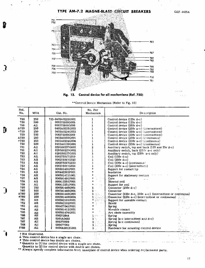
Ref. No. MVA
750 250 750 500 750 All
~750 250 .. 750 250
750 500 6750 - - 250 4;750 250
750 500 751 All 751 All 752 All 753 All 753 All 753 All 753 All 754 All 755 All 756' All 757 All 758 All 759 All 760 250 760 500
751------------------~~
752
75
758 756
759
'-----765
764 763
766 762 768
7'.0 761
Fig. 13. Control device for all mechanisms (Ref. 750)
Cat. No.
**Con:Tol Device Mechanism (Refer to Fig. 13)
No. Per Mechanism
1 I 1 1 1 1 1 1 I 2 1 1 1 1 1 1 .. .. . -
De f.C r iption
Control device (125v d-c) Control device (125v d-c) Control device (25Ov d-c) Control device (23Ov a-c) ii:ltermittent} Control device (23Ov a-c) i:""1termittent) ControLdevice (23Ov a-c) 1.i.."1termittent) Control device (23Ov a-c) (continuous) Control device (23Ov a-c) \continuous) Control device (23Ov a-c) (continuous) Auxiliary switch, top and hack (125 and 25v d-c) Auxiliary switch, back (23C ... - a-c only) Auxiliary switch, top (230\- a-c only) Coil (125v d-c) Coil (25Ov d-c) Coil (23Ov a-c) (continuous \ Coil (23Ov a-c) (intermitte::t) Support for contact tip Insulation Support for stationary contact .. -- -, Core __ ..
1 1 '
Blowout coil Support for coil Connector (25Ov d-c) Connector
6760 250 41760 250
733-0403A0225G001 006375988G005 006375988G006 0403A0225G002 0403A0224G003 006375988G009 0403A0223G001 0403A0224G004 0403A0128G001 0295B0227G002 0295B0227G002 0295B0227G001 006275017 G019 006275017G020 006275017G033 006275017G034 006591455POOl 006442392P001 006591411G001 . 006591450P001 006412255POOI 006412251 POOl 006591440GOOI 006591440GOOI 006591440G003 006591440G004 006592161POOI 006592162POOI 006477041 POOl 006591412GOOI 006591404GOOI 006272844 0365A0458 006370699 006477063 0456A0812GOOI
1 1· .. ·
Connector (125v d-c, 230\- a-c) (intermittent or continu9~s) __ :: - '" Connector (23Ov a-c) (intermittent or continuous) " ..
761 All 762 All
.. )"~ .. ' , ·.·Support for movable cont=t = 763 All 764 All 765 All 766 All 767 All 767 All 768 . All
t769 All
t Not illustrated. 6 This control device has a single arc chute.
.. ..
.. .. 1 :. -" 1 '-'., 1 1, l' ,
41 This control device has double arc chutes. __ • Quantity is (1) for control device with a sLAgle arc chute.
Quantity is (2) for control device with double arc chutes.
~~W _ Spring Movable contact Arc chute assembly
- Spring - Spring (a-c intermittent c.d d-c) . ~pring (a-c continuous)
' •. $pring : Hardware for mounting co:-.trol device
** Always specify complete information fror:: nameplate of control device when ordering r€;Jlacement parts.
17
..

('
GEF-4435A
Ref. No.
702 703 704 705 706 709 710 711 713 715 716 717 7i8 719 720 721 722 723 725 726 727 728 729 730 731 732 734 735 736 737 738 738 739
16
TYPE AM-7.2 MAGNE·BLAST CIRCUIT BREAKERS
738----------------------------,
736--------------------------~
739----------~~----------••
737----------__ ~ ____ -
725-------------------, 705 ________ ..... 706
715 --______ _ 713 --------~ 709 ---------,
710----
Fig. 12. Impact trip device (Ref. No. 702)
Impact Trip Device (Refer to Fig. 12)
Cat. No.
733-021lX010OGOOl 006591817 POOl 006591388P019 00607 6403P315 0137A6064P003 00607 6403P311 006592554G001 0065571 06P001 006558791G001 016IA5831 POOl 006443516POOI 0065571 05P001 006558746P001 006558747P001 006076401P315 0137A6048P003 006509794P001 0174V0378P001 0174V0373P001 006443666P001 0295B0227G003 0107B9305P001 006558752G001 006558751 POOl 006049320P001 006557068P009 00607 6401 P385 002236575P001 004905058G004 006443667P001 006174599G002 006174599G006 0456A0334P001
No. Reqd.
1 1 1 1 1 1 1 1 1 1 1 1 1 1 1 2 1 1
~ - -. - 1 ",' <l, 1
".", -
.".
"
1 1 1 1 3 1 1 2 1 1 3
J 1 1
735
731
732 731 730 729 718 720 719 721
727
728 723
726
717 716
722 711
Description
Impact trip device, complete Lever Locking plate Pin Roller Pin Crank Adjusting screw Eyebolt assembly Spring Bracket SpaGer Bracket Trip arm Pin Spacer Spring Rod Coupling Bracket Switch Frame assembly Core assembly Angle Felt washer Pin Pin Guide Coil frame Bracket Current trip coil, 3am'p a-c Capacitor trip coil (23Ov a':c) Rubber guard
r
e~
0
'\ )
( ,
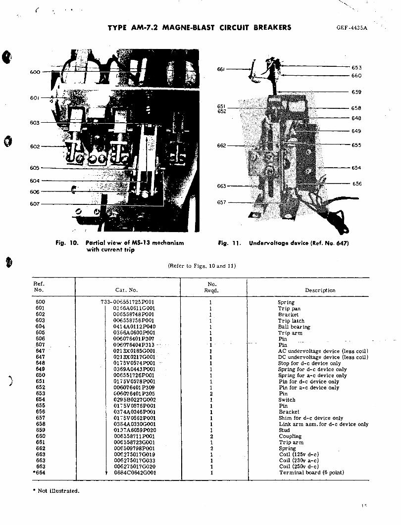
600
601
603
602
605
604
606
607
Ref. No.
600 601 602 603 604 605 606 607 647 647 648 649 650 651 652 653 654 655 656 657 658 659 660 661 662 663 663 663
*664
"' ...... , ......
'.
TYPE AM-7.2 MAGNE-BLAST CIRCUIT BREAKERS GEF -4435A
661 653
660
659
651 658 652
648
649
662 655
654
663 656
657
Fig. 10. Partial view of MS-13 mechanism with current trip
Fig. 11. Undervoltage device (Ref. No. 647)
(Refer to Figs. 10 and 11)
No. CaL No. Reqd. Description
733-006551725POOI 1 Spring 02 66A0611 GOOI 1 Trip pan 006558748POOI 1 Bracket 006558756POOI 1 Trip latch 0414A0112P040 1 Ball bearing 0366A0600POOI 1 Trip arm 006076401 P307 1 Pin - - . . --- -006076404P313 -' 1 --- - Pin 0213X0185GOO1 1 AC undervoltage device (less coil) 0213X0217GOOI 1 DC undervoltage device (less coil) 01 i5V0574POOl 1 Stop for d-c device only 0369A0443POOI 1 Spring for d-c device only 006551726POOI 1 Spring for a-c device only 01 i 5V0578POOI 1 Pin for d-c device only 006076401P309 1 Pin for a-c device only 006076401P305 2 Pin 029 5B0227GOO2 1 Switch 0175V0576POOI 1 Pin 0374A0246POOI 1 Bracket 01 -: 5V0562POOl 1 Shim for d-c device only 0384A0330G001 1 Link arm asm. for d-c device only 0137A6059P020 1 Stud 006558711 POOl 2 Coupling 006558723GOOI 1 Trip arm 00€509798POOI 2 Spring 006275017G019 1 Coil (125v d-c) 006275017G033 1 Coil (23Ov a-c) 006275017G020 1 Coil (25Ov d-c) 0684C0642GOOI 1 Terminal board (6 point)
* Not illustrated.