removing self intersections of a triangular mesh by edge...
TRANSCRIPT

Removing Self Intersections of a Triangular Mesh by Edge Swapping, Edge Hammering, and Face Lifting
Soji Yamakawa and Kenji Shimada
The Department of Mechanical Engineering Carnegie Mellon University
Abstract. This paper describes a computational method for removing self intersections of a triangular mesh. A self intersection is a situation where a part of a surface mesh collides with another part of itself, i.e., two mesh elements intersect each other. It destroys the integ-rity of the mesh and makes the mesh unusable for certain applications. A mesh generator often creates a self intersection when a relatively large element size is specified over a region with a narrow clearance. There has been no automated method that automatically removes self intersections, and such self intersections needed to be corrected by manually editing the mesh. The proposed method automatically resolves a self intersection by re-connecting edges and adjusting node locations. This technique removes a typical self in-tersection and recovers the integrity of the triangular mesh. Experimental results show the effectiveness of the proposed method.
1 Introduction
This paper describes a computational method for removing self intersections of a triangular mesh. A self intersection is a situation where a part of a surface mesh collides with another part of itself, i.e., at least two mesh elements intersect each other. A self intersection destroys the integrity of the surface mesh and makes the surface mesh unusable for certain applications. The proposed method removes such self intersections and recovers the integrity of the mesh.
A triangular mesh is used for many applications such as finite element analysis, visualization, and so on. Many of those applications require the mesh to be free of self intersections. A self intersection in a triangular mesh could cause failure of the finite element analysis or make unwanted artifacts in the visualization.
A triangular mesh is also used as a boundary of a tetrahedral mesh, and such a triangular mesh must not include a self intersection. A tetrahedral mesh is usually created by first creating a triangular mesh of the boundary of the target volume and then filling the inside of the triangular mesh with tetrahedral elements. If the boundary triangular mesh includes a self intersection, the mesh no longer defines a legitimate volume, and the tetrahedral mesh generator may create severely dis-torted elements or even fail to create a mesh at all. Therefore, a self intersection in a triangular mesh is very problematic and needs to be removed.
Theoretically, the best approach for removing self intersections is to mesh the original CAD model with more appropriate mesh sizing. However, it is often im-possible to choose adequately short edge length. For example, some types of

14 S. Yamakawa and K. Shimada
analyses require minimum edge length longer than certain threshold. For those analyses, minimum edge length condition is more important than the boundary fi-delity. The original CAD model is sometimes not available to the analyst due to confidentiality issues. When an analysis needs to be performed on a very old ge-ometry, or a legacy model, the original CAD model may no longer exist, and the model may be available only in the form of a mesh. Therefore, self-intersections need to be removed by modifying the mesh in many real-world problems.
There has been, however, no automated method for removing self intersections of a triangular mesh. Hence, the appropriate care must have been taken before a triangular mesh was created to avoid self intersections. The input geometric model needed to be de-featured, geometric constraints needed to be appropriately added or removed, and a non-uniform sizing function was often necessary. If those pre-conditioning measures were not adequate, a surface mesh generator would yield self intersections, which needed to be removed by manually editing the mesh.
The proposed method effectively removes typical self intersections created due to a defective CAD model or a very narrow clearance and recovers integrity of the triangular mesh. The proposed method takes as input a triangular mesh, open or closed, and applies to the mesh a sequence of three types of operations: (1) edge swapping, (2) edge hammering, and (3) face lifting. The edge-swapping operation has been used mainly for mesh-quality improvement and is used for reducing self intersections in this context. The edge-hammering and face-lifting operations ad-just locations of the nodes used by an intersecting triangular element. These opera-tions calculate new node locations based on the neighboring nodes and the loca-tions of intersections. The node is moved to the new location if the move reduces the number of intersecting elements without making a new intersecting element.
The organization of the paper is as follows. Section 2 presents previous work. Section 3 describes typical sources of self intersections. Section 4 explains details of the proposed method, and Section 5 discusses some potential expansions and discussions. Some experimental results are presented in Section 6. Section 7 con-cludes the paper.
2 Previous Work
The proposed method pertains to facet-repair techniques, which repair defects in-cluded in a surface mesh. A surface mesh may include two types of defects, geo-metric defects and topological defects. A self intersection is one of the common geometric defects, and a common topological defect is a gap or a hole located where the mesh needs to be closed.
Since facet-repair techniques have been of great interest in the industry, sub-stantial research has been done. Nonetheless, most of the attention has been paid to the topological aspect of the problem.
The majority of the published facet-repair techniques are gap-closure and hole-filling techniques. If a triangular mesh has a gap or hole located where the mesh needs to be closed, such a gap or hole needs to be closed. Barequet and Sharir have presented a method for closing gaps and holes of a polyhedral surface [1]. Barequet and Kumar have presented a method for repairing a geometric model

Removing Self Intersections of a Triangular Mesh 15
defined by a triangular mesh [2]. Gueziec et al. have presented a method for con-verting a polygonal surface to a manifold surface [3]. Branch et al. have presented a method for filling holes of a triangular mesh [4]. Li et al. have presented a method for repairing holes of a triangular mesh [5]. Those gap-closure and hole-filling techniques identify gaps and holes that need to be closed and then insert tri-angular elements and/or stitch the edges together so that gaps and holes are filled by triangular elements.
Gap closure and hole filling are important to recover the topological integrity of a triangular mesh. However, it is also necessary to remove self intersections and recover the geometric integrity. Self-intersection avoidance has been relying mainly on a priori methods. In other words, adequate pre-conditioning needed to be performed before a triangular mesh was created so that the mesh generator would not yield a self intersection.
One of the common sources of a self intersection is a very small feature, which is usually irrelevant to the purpose of the mesh. Ribelles et al. have presented a method that automatically removes features of a geometric model [6]. Lee et al. also have presented another approach for small-feature suppression [7].
A self-intersection can also be avoided by identifying features and appropri-ately adding geometric constraints near the features. Numerous researches have been done for feature-line identification [8-12]. Jiao has presented a method for identifying features of a geometric model and preserves them during the mesh-generation process [13].
Alternatively, a self-intersection can be avoided by creating smaller elements near small features. Quadros et al. have presented a method for automatically cre-ating an element-sizing function based on the input geometry [14].
Self intersections can be avoided by embedding intersection curves on a mesh and then dividing the mesh into a set of non-intersecting sub-meshes [15]. This method, however, divides a mesh into multiple meshes and can be utilized only in limited types of applications.
Despite the extensive research on automatic feature identification and removal techniques, those techniques are not always adequate for avoiding all self inter-sections. If the mesh generator could not avoid creation of self intersections in a triangular mesh, the user needed to manually edit the mesh to remove those self intersections.
The proposed method modifies a triangular mesh and reduces self intersections. It is useful for reducing the manual mesh editing when the mesh generator can not avoid self intersections.
3 Typical Sources of a Self Intersection
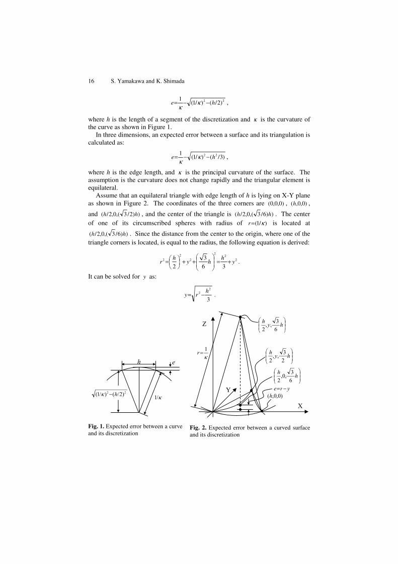
Even when the CAD model itself does not include a self intersection, there is a possibility that the mesh generator creates a self intersection when an excessively large element size is specified. A large element size yields a large error (in dis-tance) between the mesh surface and the original surface. In two dimensions, when a curve is discretized into line segments, an expected error between a curve and its discretization is calculated as:
16 S. Yamakawa and K. Shimada
22 )2/()/1(1
he −−= κκ
,
where h is the length of a segment of the discretization and κ is the curvature of the curve as shown in Figure 1.
In three dimensions, an expected error between a surface and its triangulation is calculated as:
)3/()/1(1 22 he −−= κκ
,
where h is the edge length, and κ is the principal curvature of the surface. The assumption is the curvature does not change rapidly and the triangular element is equilateral.
Assume that an equilateral triangle with edge length of h is lying on X-Y plane as shown in Figure 2. The coordinates of the three corners are )0,0,0( , )0,0,(h ,
and ))2/3(,0,2/( hh , and the center of the triangle is ))6/3(,0,2/( hh . The center of one of its circumscribed spheres with radius of )/1( κ=r is located at
))6/3(,0,2/( hh . Since the distance from the center to the origin, where one of the triangle corners is located, is equal to the radius, the following equation is derived:
22
2
22
2
36
3
2y
hhy
hr +=⎟
⎟⎠
⎞⎜⎜⎝
⎛++⎟
⎠⎞
⎜⎝⎛= .
It can be solved for y as:
3
22 h
ry −= .
22 )2/()/1( h /1
h e
hyh63,,
2
)0,0,(h
hyh23,,
2
1r
yre
hh63,0,
2
X
Z
Y
Fig. 1. Expected error between a curve and its discretization
Fig. 2. Expected error between a curved surface and its discretization

Removing Self Intersections of a Triangular Mesh 17
Since the expected error can be calculated as the difference between the radius and the distance between the element to the center of the sphere, the expected er-ror becomes:
)3/()/1(1 22 he −−= κκ
. (1)
Therefore, when two surfaces are separated with a small clearance d, the edge length h should be small enough so that the expected error is smaller than d.
However, in practice, element size is often decided based on the application in which the mesh is used, and it can be way too large for the surface clearance of the original geometric model. Such a large element size yields self intersections in the mesh. For example, Figure 3 (a) shows a CAD model that includes two co-axial cylindrical surfaces. The radii of the outer and inner cylindrical surfaces are 5.0 and 4.8, respectively. Therefore, the clearance between the two surfaces is 0.2. The curvature of the outer surface is 1.0/5.0=0.2. From equation (1), the edge length of the mesh needs to be less than 2.42. Figure 3 (b) shows a triangular mesh created from this CAD model with an average edge length of 2.42, and it does not include a self intersection. However, if the same geometry is meshed with average edge length of 3, some self intersections are clearly visible as shown in Figure 3 (c). In this particular case, self intersections can be avoided by identi-fying cylindrical surfaces and adding some mesh constraints on the surface. Fig-ure 3 (d) shows some new constrained edges added by the polygon-crawling method [12]. The mesh generator preserves those constrained edges, and the out-put triangular mesh does not include a self intersection as shown in Figure 3 (e).
Ideally, a sufficiently small element size needs to be chosen or appropriate mesh constraints need to be added for the regions of small clearance. However, some of such ill conditions are often overlooked. Particularly, such ill conditions tend to be left untreated if they are:
1. contained within a very small feature, or 2. away from the point of interest for the application in which the mesh is
used.
Such less-visible ill conditions are most likely left untreated before the model is given to the mesh generator. Even if all of those ill conditions are detected, a complex model could have hundreds of them and could take substantial manual operations to correct or add constraints to all of them. As discussed in Section 2, if such an ill condition was overlooked and the mesh generator created self inter-sections, the user needed to manually correct those self intersections.
The next section explains an automated method for removing self intersections included in a triangular mesh. The method substantially reduces the manual op-erations required to eliminate self intersections to recover the integrity of the mesh.

18 S. Yamakawa and K. Shimada
Fig. 3. A narrow clearance causing self intersections
4 Detail of the Proposed Method
4.1 Improvement Criteria
The proposed method uses three types of operations, edge swapping, edge ham-mering and face lifting, which are explained later in this section. Although the three operations are effective in reducing self intersections, those operations can-not always guarantee the successful reduction of self intersections. In the worst case, those operations could make the situation worse. Therefore, the proposed method needs criteria to test the improvement, and the proposed method will not apply the operations if the criteria cannot be met.
The improvement criteria used by the proposed method are as follows: 1. The number of intersecting triangles decreases. 2. No new intersecting triangle is created.
The first criterion guarantees that the process terminates within finite computa-tional time. The mesh has a finite number of intersecting triangles, and the edge-swapping, edge-hammering and face-lifting operations do not change the total number of triangles. Therefore, the process terminates when no more reduction of the intersecting triangles is possible.
(c) Triangular mesh with average edge length of 3.
Intersecting elements
(d) Additional constrained edges added by the polygon-
crawling method
New constrained edges
(e) Triangular mesh with average edge length of 3. Additional constrained edges have successfully
prevented self intersections
(a) Original CAD model (b) Triangular mesh with av-erage edge length of 2.42

Removing Self Intersections of a Triangular Mesh 19
The second condition prevents the effect of the edge-swapping, edge-hammering, and face-lifting operations from propagating through the mesh. If the number of in-tersecting triangles is reduced by creating a new intersecting triangle, the new inter-section needs to be removed by a subsequent edge-swapping, edge-hammering, or face-lifting operation. As a result, the effect of those operations could propagate through the mesh. Such propagation can be prevented by the second condition.
Fig. 4. Removing a self intersection by edge swapping
Fig. 5. An Example of edge hammering
4.2 Edge Swapping
Edge swapping reconnects an edge shared by two triangles. When an edge con-necting nodes a and b is shared by two triangles T1 and T2, and if triangle T1 is us-ing nodes a, b, and c, and T2 is using b, a, and d, triangles T1 and T2 are replaced with triangles cad and dbc as shown in Figure 4. Edge swapping removes edge ab and creates edge cd. The proposed method applies edge swapping to an edge used by an intersecting triangle if it satisfies the improvement criteria.
4.3 Edge Hammering
Edge Hammering moves a node and corrects an edge sticking out of another trian-gle. When a triangular mesh is created from two curved surfaces with a small clearance, a self intersection can be created as shown in Figure 5 (a). In this
(a) Five triangles are intersecting with another triangle. Dashed lines are behind the outside layer of the triangular mesh.
(b) Intersections are removed by Edge Hammering
a
b
d
1T
2T
a
b
c
d 1T
2T

20 S. Yamakawa and K. Shimada
(a) Three edges connected to node a are intersecting with other triangles.
x1
x2 x4
x3
(Schematic drawing)
ab
c
x1 d
x4
a
b
cx1
d
x2
(b) Moving node a to (x4+b)/2 reduces intersections
(c) Moving node a to (x1+ x2)/2 re-duces intersections
a
bc
x5
x6 d
(d) Moving node a beyond x1 yields new intersections.
a
b
c
x1
x2 x4
d
x3
a'1
a'2 a'3
a'
b
cd
(a'1+a'2+a'3)/3
(e) Three candidate locations (d) Moving node a to the average of the three candidate locations reduces intersections with-
out creating a new intersecting triangle.
a
b
x1
x2 x4
x3
d1T
2T4T
3Tc
Fig. 6. Calculating candidate points to which a node is moved
example, five edges from the inside-layer triangles are sticking out of an outside-layer triangle. Such a self intersection can be removed by moving the node of the intersecting edges as shown in Figure 5 (b).
If an edge is intersecting with another triangle at one point, the intersection on the edge will disappear by moving one of the edge nodes toward the other node beyond the intersecting point. For example, in Figure 6 (a), edge ab is intersect-ing with triangle T4 at x4. Edge ab will no longer have an intersection if node a is moved toward node b beyond x4 as shown in Figure 6 (b). In this example, this move also makes triangles 2T , 3T , 4T , and abd free of intersection. The new lo-cation of node a can be anywhere between x4 and b to make edge ab intersection-free. The mid point, (x4+b)/2, is advantageous because it does not make edge ab too short and makes a reasonable clearance from x4.
If an edge is intersecting with other triangles at more than one point, the inter-section may be reduced by moving one of the edge nodes toward the other node beyond the first intersecting point before reaching the second. For example, edge ac in Figure 6 (a) is intersecting with triangles 1T and 2T at x1 and x2, respec-tively. If node a is moved toward node c beyond x2 before x1, intersection x2 dis-appears, and triangles 2T , 3T , 4T , and abd become free of intersection as shown in Figure 6 (c). However, if node a is moved beyond x1, a new intersection x5 will be created as shown in Figure 6 (d). From this observation, if an edge intersects

Removing Self Intersections of a Triangular Mesh 21
with other triangles at more than one point, one of the edge nodes should be moved toward the other node beyond the first intersection to reduce the number of intersections. However, moving the node beyond the second intersection will cre-ate a new intersection. Node a can be moved to anywhere between the first and second closest intersections. The simplest choice of the point is the mid point of the first two intersections.
Since a node can be connected to more than one intersecting edge, the node can have multiple candidate points. If edge abn is the nth intersecting edge connected to node a, the nth candidate point a'n is calculated as:
(a) If edge abn is intersecting with another triangle at a single point x, candi-date point a'n is calculated as a'n=(x+bn)/2, and
(b) If edge abn is intersecting with other triangles at multiple points x1, x2, …, and xk, and x1 and x2 are the first and second closest intersection to node a, candidate point a'n is calculated as a'n=(x1+x2)/2.
The proposed method moves node a to the average of the candidate points:
∑= n/na'a' ,
if the move satisfies the improvement criteria described in Section 4.1. In the example shown in Figure 6, three candidate locations, a'1 and a'2 are cal-
culated as:
a'1=(x4+b)/2
a'2=(x1+x2)/2
a'3=(x3+d)/2,
as shown in Figure 6 (e), and node a is moved to a'=(a'1+a'2+a'3)/3 because trian-gles 2T , 3T , 4T , and abd become intersection free without making a new inter-secting triangle. Although triangles 1T , acb, and acd are still intersecting, the move yields no new intersecting triangles, and the three remaining intersecting tri-angles can be made intersection free by subsequent edge hammering and face lift-ing operations.
4.4 Face Lifting
The face lifting operation moves a triangle at a time to reduce the number of inter-sections. For example, a highlighted triangle in Figure 7 (a) is intersecting with multiple edges. The face-lifting operation moves the triangle to its normal direc-tion and removes the intersections as shown in Figure 7 (b).
Assume that triangle T1, consisting of three nodes t1, t2, and t3, is intersecting with one or more edges, and the nodes p1, p2, …, pn are the nodes used by the in-tersecting edges. The unit normal vector of T1 is n1, and ε is the given clearance requirement between a triangle and a node.
The minimum and maximum of the signed distances of nodes pi {i=1 to n} relative to T1, denoted as dmin and dmax respectively, are then calculated as:

22 S. Yamakawa and K. Shimada
Fig. 7. Face-lifting operation
dmin=min( 11i ntp ⋅− )( ),
dmax=max( 11i ntp ⋅− )( ).
The proposed method moves triangle T1 to two possible new locations, by off-setting )( max1 ε+dn and )( min1 ε−dn from the original location. And for each new lo-cation, the proposed method tests if the move satisfies the improvement criteria described in Section 4.1.
If only one of the two new locations satisfies the improvement criteria, triangle T1 is moved to the new location that satisfies the improvement criteria. If both
a b
c
d e f
T1
n1 dmax
dmin
T1)( max1 ε+dn
a bc
de
f
T1
T3T2
T1
)( min1 ε−dn
T3T2
(a) Triangle T1 intersecting with six edges, ad, ae,be, bf, cd,and cf.
a bc
d e f
T1
T2 T3
(Schematic drawing) (b) Computing the minimum and maximum of the signed heights of nodes a, b, c, d, e,
and f based upon T1.
(c) Moving T1 by )( max1 ε+dn re-moves all the intersections
(d) Moving T1 by )( min1 ε−dn makes T1
free of intersections. However, it makes new intersecting triangles, T2 and T3.
Fig. 8. Calculating possible new locations of an intersecting triangle
(a) A triangle intersecting with multiple edges
(b) Face-lifting operation removes the intersections

Removing Self Intersections of a Triangular Mesh 23
moves satisfy the improvement criteria (implies that the intersecting edges are dis-connected from the other part of the mesh that T1 belongs to,) T1 is moved to the new location that makes the move smaller.
For example, in Figure 8 (a), triangle T1 intersects with six edges, ad, ae, be, bf, cd, and cf. The minimum and maximum of the signed heights of the nodes of the intersecting edges are calculated as shown in Figure 8 (b). If the triangle T1 is moved by )( max1 ε+dn , triangle T1 becomes free of intersection without making a new intersecting triangle as shown in Figure 8 (c). Therefore, it satisfies the im-provement criteria described in Section 4.1. However, if T1 is moved by )( min1 ε−dn as shown in Figure 8 (d), triangles T2 and T3, which were intersection free before the move, intersect with some of the edges. Therefore, it violates the improve-ment criterion. In this case, triangle T1 is thus moved by )( max1 ε+dn from the original location.
4.5 Order-Dependency Issues
The result of edge-swapping, edge-hammering, and face-lifting operations de-pends on the order in which the operations are applied. If the operations are ap-plied to the mesh in an inappropriate order, they may either make an unnecessarily large deformation to the mesh or simply fail to reduce the self intersections. However, it is virtually impossible to find the ideal order of the operations.
In this research, we have tested several different measures in an attempt to re-duce the adverse effect caused by the order dependency. In the first approach, we have applied edge swapping first, edge hammering second, and face lifting last. Since edge swapping does not move nodes, it seemed to have the least impact on the geometry. Edge hammering moves one node at a time while face lifting moves three nodes at a time. Edge hammering thus seems to have less impact on the geometry compared to face lifting. Although this approach gave somewhat good results, it often gave less than satisfactory results. That led to the two-phase approach described below.
To reduce the adverse effect caused by the order-dependency, the proposed method applies a sequence of edge-swapping, edge-hammering, and face-lifting operations in two phases: (1) cost-calculation phase and (2) implementation phase.
In the cost-calculation phase, a sequence of edge-swapping, edge-hammering, and face-lifting operations are applied to all applicable edges, nodes, and ele-ments. After each operation, the cost of the operation is calculated, and then the modifications made to the mesh by the operation are retracted back to the original state of the mesh. Therefore, the mesh does not change before and after the cost-calculation phase.
The cost of an operation is a measurement that evaluates the magnitude of de-formation of the mesh made by the operation, which can be measured as a change of volume made by the operation. The cost of the edge-swapping operation is the volume of a tetrahedron enclosed by the two triangles deleted by the operation and the two new triangles created by the operation as shown in Figure 9 (a).

24 S. Yamakawa and K. Shimada
(b) Cost of the edge-hammering operation
(c) Cost of the face-lifting operation
(a) Cost of the edge-swapping operation
Two triangles deletedby the operation
Two triangles created by the operation
A tetrahedron enclosed by the four triangles
Triangles beforethe operation
Triangles after the operation
A volume enclosed by the triangles before and after the operation
nTnT '
TnT 'TnT '
Triangles before the operation
Triangles after the operation
A volume enclosed by the triangles before and after the operation
Fig. 9. Cost of the edge-swapping, edge-hammering, and face-lifting operations
The cost of the edge-hammering operation is calculated as follows. Let 1T , 2T , …, nT be the triangles sharing the node to be moved by the operation. The
operation moves the node, and nT becomes nT ' . The cost of the edge-hammering operation is the volume enclosed by 1T , 2T , …, nT , and 1'T , 2'T ,…, nT ' as shown in Figure 9 (b).
The cost of the face-lifting operation is calculated as follows. Let T be the tri-angle to be moved by the operation and 1T , 2T , …, nT be the triangles sharing at least one node with T . The operation moves T to 'T , and nT becomes nT ' . The cost of the edge-hammering operation is the volume enclosed by T , 'T , 1T , 2T , …, nT , and 1'T , 2'T ,…, nT ' as shown in Figure 9 (c).
Then, in the implementation phase, the edge-swapping, edge-hammering, and face-lifting operations are applied to the mesh in the order of ascending cost.
5 Potential Expansions and Discussions
5.1 Expanding the Proposed Method for a Quadrilateral Mesh
The proposed method can easily be expanded so that it can deal with a quadrilat-eral mesh by the following steps:
1. Tessellate every quadrilateral by adding a diagonal edge while keeping track of which triangle comes from which quadrilateral.

Removing Self Intersections of a Triangular Mesh 25
2. Apply the proposed method. 3. Merge triangles to re-construct the quadrilaterals.
However, there are two remaining issues that need to be addressed for this ex-pansion as follows.
(a) Edge preservation vs. effectiveness Some quadrilaterals may not be re-constructed after applying the proposed method due to edge swapping. To guarantee the re-construction, edge swap-ping needs to be carefully applied so that edges of the original quadrilaterals are preserved. However, this limitation could reduce the effectiveness of the proposed method. (b) Non-planar quadrilateral Four nodes of a quadrilateral element may not be co-planar, and the geometry of a quadrilateral element is a bi-linear surface. Therefore, tessellating a quad-rilateral into two triangles changes the geometry, and some self intersections may not be detected after the tessellation. Or, even if the triangular mesh is made self-intersection free by the proposed method, it does not guarantee that the quadrilateral mesh is also self-intersection free after quadrilateral elements are re-constructed.
Further research is needed for addressing these issues.
5.2 Locally Adjusting the Clearance Requirement
The proposed method takes the parameter ε , a clearance requirement for the face-lifting operation, as input. The face-lifting operation moves an intersecting trian-gular element in its normal direction so that it will have a clearance of ε .
However, in some cases, it is ideal to vary ε over the domain. For example, if the thickness of the geometry substantially changes over the domain, ε should be proportional to the local thickness of the domain.
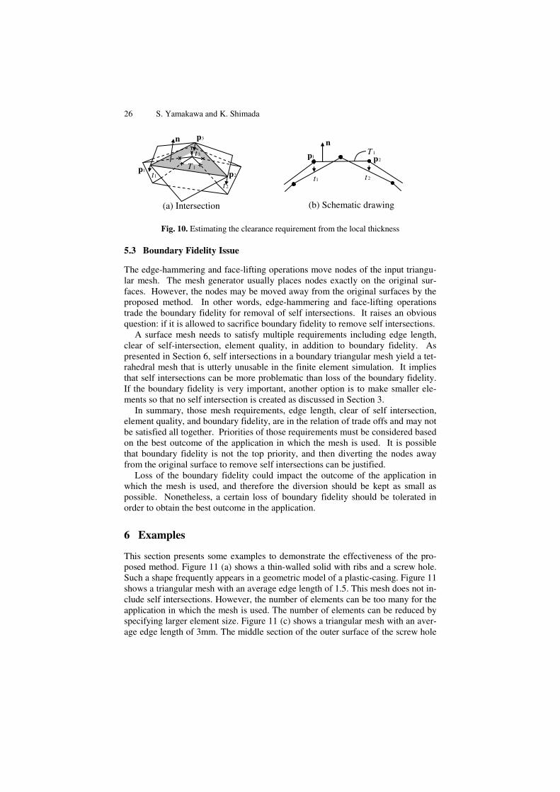
The proposed method can be adapted to such requirement with a small modifi-cation. When triangle 1T is being moved by the face-lifting operation, instead of taking ε as a user input, it can be calculated as follows.
Assume triangle 1T consists of nodes 1p , 2p , and 3p , and its normal is n . nt is the distance that a ray travels from np in the direction n− until it hits another triangular element as shown in Figure 10. If the ray does not hit another triangle,
nt is zero. Each of nt gives a rough estimation of the thickness at np . If at least two of the three nt s are non-zero, ε is taken from the median of nt s. If only one
nt is non-zero, ε is taken from the non-zero nt . If all three nt s are zero, the face-lifting operation is not attempted, and this intersection is deferred to the edge-swapping and edge-hammering operations.
In some applications, the clearance can also be specified relative to the edge length of the triangle to be moved. For example, if the triangular mesh is used as the boundary of a tetrahedral mesh, and if the maximum aspect ratio of the tetra-hedral mesh needs to be smaller than γ , the required clearance ε must be γ/1 times the longest edge length of the triangle. In this application, a similar adapta-tion is also possible for the edge-hammering operation.
26 S. Yamakawa and K. Shimada
Fig. 10. Estimating the clearance requirement from the local thickness
5.3 Boundary Fidelity Issue
The edge-hammering and face-lifting operations move nodes of the input triangu-lar mesh. The mesh generator usually places nodes exactly on the original sur-faces. However, the nodes may be moved away from the original surfaces by the proposed method. In other words, edge-hammering and face-lifting operations trade the boundary fidelity for removal of self intersections. It raises an obvious question: if it is allowed to sacrifice boundary fidelity to remove self intersections.
A surface mesh needs to satisfy multiple requirements including edge length, clear of self-intersection, element quality, in addition to boundary fidelity. As presented in Section 6, self intersections in a boundary triangular mesh yield a tet-rahedral mesh that is utterly unusable in the finite element simulation. It implies that self intersections can be more problematic than loss of the boundary fidelity. If the boundary fidelity is very important, another option is to make smaller ele-ments so that no self intersection is created as discussed in Section 3.
In summary, those mesh requirements, edge length, clear of self intersection, element quality, and boundary fidelity, are in the relation of trade offs and may not be satisfied all together. Priorities of those requirements must be considered based on the best outcome of the application in which the mesh is used. It is possible that boundary fidelity is not the top priority, and then diverting the nodes away from the original surface to remove self intersections can be justified.
Loss of the boundary fidelity could impact the outcome of the application in which the mesh is used, and therefore the diversion should be kept as small as possible. Nonetheless, a certain loss of boundary fidelity should be tolerated in order to obtain the best outcome in the application.
6 Examples
This section presents some examples to demonstrate the effectiveness of the pro-posed method. Figure 11 (a) shows a thin-walled solid with ribs and a screw hole. Such a shape frequently appears in a geometric model of a plastic-casing. Figure 11 shows a triangular mesh with an average edge length of 1.5. This mesh does not in-clude self intersections. However, the number of elements can be too many for the application in which the mesh is used. The number of elements can be reduced by specifying larger element size. Figure 11 (c) shows a triangular mesh with an aver-age edge length of 3mm. The middle section of the outer surface of the screw hole
1T n
1t 2t
1p2p
1T
n
2t 1t
3t
1p 2p
3p
(a) Intersection (b) Schematic drawing

Removing Self Intersections of a Triangular Mesh 27
(d) Triangular mesh with 3mm average edge length repaired with the proposed method. The
mesh includes no self intersection.
(e) Tet mesh created from a triangular mesh with self intersections
(f) Tet mesh created from a triangular mesh repaired by the proposed method
(c) Triangular mesh with 3mm average edge length including numerous self inter-
sections.
(a) Original geometric model (b) Triangular mesh with 1.5mm average edge length does not include a self intersection
Fig. 11. Sample model with ribs and a screw hole
is collapsed to a single edge, and it intersects with the inside wall. Some inside-wall elements also collide with the outer-wall of the fillet. The proposed method suc-cessfully removes all self intersections as shown in Figure 11 (d). Figure 11 (e) shows a tetrahedral mesh created from the triangular mesh shown in Figure 11 (c). Due to the self intersections in the input triangular mesh, the output tetrahedral mesh has some exterior edges that are shared by more than two exterior triangular elements. Figure 11 (f) shows a tetrahedral mesh created from the triangular mesh shown in Figure 11 (d). Since no self intersection is included in the triangular mesh, the output tetrahedral mesh is a valid and usable in the finite element analysis.
Figure 12 (a) shows a CAD model of a plastic casing of a telephone. Figure 12 (b) is a triangular mesh of the model meshed with an average edge length of 4mm. With this edge length, the mesh generator does not create a self intersection. Fig-ure 12 (c) is a triangular mesh with 10mm average edge length. This edge length yields numerous self intersections as shown in Figure 12 (d). Note that the major-ity of the elements are intersection free. Only a small fraction of the elements are intersecting. Despite the small percentage of intersecting elements, these self in-tersections could make the mesh utterly unusable for the application. The pro-posed method successfully removes all the intersections. The changes made by the

28 S. Yamakawa and K. Shimada
(a) Input geometric model (c) 10mm average edge length yields numerous
self intersections.
(d) Intersecting triangular elements
(e) Close up of intersect-ing elements
(f) Intersection removed by the proposed method
(b)Triangular mesh with 4mm average edge length does not include a self intersection.
Fig. 12. Sample model of a plastic casing of a telephone
proposed method are hardly visible without zooming into the specific locations. Figure 12 (e) shows a close up look of two of the self intersections included in the 10mm mesh, and the proposed method removes them as shown in Figure 12 (f).
7 Conclusions
This paper has presented a computational method for removing self intersections included in a triangular mesh. The method systematically applies edge-swapping, edge-hammering, and face-lifting operations to the input triangular mesh. The proposed method has been applied to many test cases, and the results showed the effectiveness of the proposed method.
References
[1] Barequet, G., Sharir, M.: Filling Gaps in the Boundary of a Polyhedron. Computer Aided Geometric Design 12, 207–229 (1995)
[2] Barequet, G., Kumar, S.: Repairing CAD Models. In: Proceedings of IEEE Visualiza-tion 1997, pp. 363–370 (1997)
[3] Gueziec, A., Taubin, G., Lazarus, F., Horn, B.: Cutting and Stitching: Converting Sets of Polygons to Manifold Surface. IEEE Transactions on Visualization and Computer Graphics 7, 136–151 (2001)
[4] Branch, J., Prieto, F., Boulanger, P.: A Hole-Filling Algorithm for Triangular Meshes Using Local Radial Basis Function. In: Proceedings of 15th International Meshing Roundtable, pp. 411–431 (2006)

Removing Self Intersections of a Triangular Mesh 29
[5] Li, F., Chen, B., Leng, W.-h.: A Hole Repairing Method for Triangle Mesh Surfaces. In: Proceedings of International Conference on Computational Intelligence and Secu-rity, pp. 972–975 (2006)
[6] Ribelles, J., Heckbert, P., Garland, M., Stahovich, T., Srivastava, V.: Finding and Removing Features from Polyhedra. In: Proceedings of ASME Design Automation Conference (2001)
[7] Lee, K.Y., Armstrong, C.G., Price, M.A., Lamont, J.H.: A Small Feature Suppres-sion/Unsuppression System for Preparing B-Rep Models for Analysis. In: Proceed-ings of ACM Symposium on Solid and Physical Modeling, pp. 113–124 (2005)
[8] Nomura, M., Hamada, N.: Feature Edge Extraction from 3D Triangular Meshes Using a Thinning Algorithm. In: Proceedings of SPIE - Vision Geometry X, pp. 34–41 (2001)
[9] Jiao, X., Heath, M.T.: Feature Detection for Surface Meshes. In: Proceedings of 8th International Conference on Numerical Grid Generation in Computational Field Simulations, pp. 705–714 (2002)
[10] Baker, T.J.: Identification and Preservation of Surface Features. In: Proceedings of 13th International Meshing Roundtable, pp. 299–309 (2004)
[11] Yoshizawa, S., Belyaev, A., Seidel, H.-P.: Fast and Robust Detection of Crest Lines on Meshes. In: Proceedings of ACM Symposium on Solid and Physical Modeling, pp. 227–232 (2005)
[12] Yamakawa, S., Shimada, K.: Polygon Crawling: Feature-Edge Extraction from a General Polygonal Surface for Mesh Generation. In: Proceedings of 14th International Meshing Roundtable, pp. 257–275 (2005)
[13] Jiao, X.: Volume and Feature Preservation in Surface Mesh Optimization. In: Pro-ceedings of 15th International Meshing Roundtable, pp. 359–373 (2006)
[14] Quadros, W.R., Vyas, V., Brewer, M., Owen, S.J., Shimada, K.: A Computational Framework for Generating Sizing Function in Assembly Meshing. In: Proceedings of 14th International Meshing Roundtable, pp. 55–72 (2005)
[15] Glimm, J., Simanca, S.R., Tan, D., Tangerman, F.M., Vanderwoude, G.: Front Track-ing Simulations of Ion Deposition and Resputtering. SIAM Journal on Scientific Computing 20, 1905–1920 (1999)