removal & installation -...
TRANSCRIPT

REMOVAL & INSTALLATION
FUEL PRESSURE RELEASE
To release fuel pressure, remove rear seat cushion and fuel pump access plate. Disconnect fuel pump connector. See Fig. 1 . Start and run engine until it stalls. Turn ignition off. Once repairs have been completed, reconnect fuel pump connector and install access plate and rear seat cushion.
Fig. 1: Locating Fuel Pump Electrical Connector Courtesy of KIA MOTORS AMERICA, INC.
ENGINE
Removal & Installation
1. Release fuel pressure. See FUEL PRESSURE RELEASE . Remove windshield washer from hood.
NOTE: For reassembly reference, label all electrical connectors, vacuum hoses and fuel lines before removal. Also place mating marks on engine hood and other major assemblies before removal.
2002 Kia Sportage
2002 ENGINES' '2.0L 4-Cylinder - Sportage
2002 Kia Sportage
2002 ENGINES' '2.0L 4-Cylinder - Sportage

Remove hood. Disconnect battery cables. Remove battery cover, battery and battery tray. Remove air inlet duct and air cleaner assembly. On A/T models, remove accelerator cable and transmission control cable.
2. On all models, pull back throttle shaft, and disconnect accelerator cable. Remove resonance chamber mounting bolt, chamber bolt and air silencer. Remove IAC air hose, breather hose and vacuum line from air intake tube.
3. Disconnect MAF sensor connector. Loosen air inlet hose clamp from MAF sensor. Remove 3 bolts from air intake tube to throttle body. Remove air intake hose and air intake tube as an assembly.
4. Remove radiator cap. Loosen radiator drain plug, and drain engine coolant. Tighten radiator drain plug. Loosen and remove upper radiator hose clamps, and remove upper radiator hose. Remove 4 thermo-modulated fan nuts.
5. Remove 5 cooling fan shroud bolts. Remove fan and fan shroud as an assembly. Loosen generator mounting bolts. Loosen generator drive belt by loosening adjusting bolt.
6. Remove fan pulley. Remove generator electrical connectors. Remove heater hoses from pipes. 7. Label and disconnect all necessary electrical connectors, wires, hoses and control cables for engine
removal. Plug all fuel hoses to avoid leakage. Remove radiator. 8. Raise and support vehicle. Remove undercover mounting bolts and undercover. Loosen A/C idler pulley
lock nut, and remove A/C drive belt by loosening adjusting bolt. Remove A/C idler pulley bracket mounting bolts and A/C idler pulley bracket.
9. Remove A/C compressor mounting bolts and A/C compressor. Position A/C compressor away from engine. Loosen power steering pump lock bolt and mounting bolt, and remove power steering drive belt. Remove power steering pump lock bolt and mounting bolt. Position power steering pump away from engine.
10. Remove intake manifold support bracket bolts and bracket. Remove starter bolts. Unbolt starter, and wire aside so there is no tension on wire harness. Remove converter inlet pipe flange lock nuts.
11. Remove front exhaust bracket bolt. On M/T models, remove exhaust bracket-to-clutch housing mounting bolts and bracket. On A/T models, remove converter housing mounting bolts and bracket. On M/T models, remove clutch housing-to-engine mounting bolts. On A/T models, remove converter housing-to-engine mounting bolts.
12. On all models, lower vehicle. On A/T models, remove 6 drive plate-to-torque converter bolts. On all models, support transmission, and connect engine hoist to engine. Remove left side and right side engine mounting bolts.
13. Lift engine up until free of frame, and move forward to clear transmission. Disconnect 3 remaining electrical connectors at back of engine. Check for any other electrical wiring still connected to engine assembly and disconnect, if necessary. Ensure engine is free of any other components. Remove engine from vehicle.
Installation
To install, reverse removal procedure. Tighten all bolts/nuts to specification. See TORQUE SPECIFICATIONS . Check fluid levels, and fill as necessary.
INTAKE MANIFOLD
Removal
2002 Kia Sportage
2002 ENGINES' '2.0L 4-Cylinder - Sportage

1. Release fuel system pressure. See FUEL PRESSURE RELEASE . Disconnect negative battery cable. Remove 2 accelerator cable bracket-to-cylinder head cover bolts. Remove air intake tube-to-cylinder cover bolts. Remove air intake tube-to-throttle body bolts. Loosen clamp from air intake hose to Mass Airfow (MAF) sensor.
2. Remove idler control valve hose, breather hose and vacuum line from air intake tube. Remove air intake tube and air intake hose as an assembly. Remove PCV hose from dynamic chamber. Remove radiator cap. Loosen radiator drain plug, and drain engine coolant. Tighten radiator drain plug.
3. Remove purge solenoid valve vacuum hose from dynamic chamber. Disconnect electrical connector from throttle position sensor. Disconnect electrical connection from idle air control valve. Remove heater hoses from pipes. Remove engine-to-body ground bolt at intake manifold assembly. Remove heater hoses from below throttle body.
4. Remove brake booster vacuum line. Remove vacuum hose from fuel pressure regulator. Remove dynamic chamber support brackets and bolts. Disconnect electrical connectors from fuel injectors by pushing on wire clips. Release fuel system pressure. See FUEL PRESSURE RELEASE .
5. Disconnect fuel line from pressure regulator. Disconnect fuel return line from fuel rail assembly. Remove intake manifold support brackets (side and rear).
6. Using wrench, remove oil filter. Remove bolts and nuts from intake manifold. Remove by-pass pipe from heater hose. Remove intake manifold and gasket.
Installation
Clean gasket mating surfaces. Install intake manifold with NEW gasket. Install by-pass pipe. Install intake manifold bolts and nut, and tighten to specification. See Fig. 2 . To complete installation, reverse removal procedure. Tighten all bolts and nuts to specification. See TORQUE SPECIFICATIONS .
2002 Kia Sportage
2002 ENGINES' '2.0L 4-Cylinder - Sportage

Fig. 2: Intake Manifold Mounting Bolt Locations Courtesy of KIA MOTORS AMERICA, INC.
EXHAUST MANIFOLD
Removal
Disconnect negative battery cable. Loosen air intake hose clamps, and remove air intake hose. Remove exhaust manifold heat shield. Remove 5 converter inlet pipe flange lock nuts. Remove exhaust manifold bolts. Remove exhaust manifold and gasket.
Installation
2002 Kia Sportage
2002 ENGINES' '2.0L 4-Cylinder - Sportage

Ensure gasket mating surfaces are clean and flat. Install NEW gasket to cylinder head. Install manifold. Tighten manifold bolts and nuts evenly to specification, starting from center bolt and alternating outward. Install NEW gasket, and attach converter inlet pipe. To complete installation, reverse removal procedure. See TORQUE SPECIFICATIONS .
CYLINDER HEAD
Removal
1. Disconnect negative battery cable. Remove brake booster vacuum hose from dynamic chamber. Remove fuel line from pressure regulator and return line located at rear of dynamic chamber.
2. Remove engine-to-body ground wire from intake manifold and harness bracket. Remove radiator cap. Remove radiator drain plug, and drain engine coolant. Tighten radiator plug.
3. Remove purge solenoid valve vacuum hose from dynamic chamber. Loosen clamps, and disconnect upper radiator hose. Remove intake manifold support bracket bolts and bracket. Remove converter inlet pipe flange lock nuts. Remove timing belt. See TIMING BELT .
4. Remove cylinder head cover. Remove cylinder head bolts in sequence. See Fig. 3 . Disconnect wire harness connectors on back of cylinder head. Lift cylinder head off cylinder block with intake and exhaust manifolds attached, and remove cylinder head assembly from vehicle.
Inspection
Carefully clean carbon and gasket material from all mating surfaces. Clean threads of cylinder head bolts. Use tap to clean threads in engine block. Check cylinder head for warpage and cracks. Resurface or replace head if it is not within specification. Check valve train components. Replace or resurface components if not within specification. See CYLINDER HEAD and VALVES & VALVE SPRINGS tables under ENGINE SPECIFICATIONS.
Installation
1. Install cylinder head gasket. Place cylinder head with manifolds installed over cylinder block, and attach 3 wire harness connectors to back of head. Install cylinder head assembly and cylinder head bolts. Using 3 equal steps, tighten cylinder head bolts in specified sequence. See Fig. 14 . See TORQUE SPECIFICATIONS .
2. Install timing belt. See TIMING BELT . Install converter inlet pipe flange lock nuts, and tighten to specification. See TORQUE SPECIFICATIONS .
3. Install upper radiator hose, and tighten clamps. Fill radiator, and install cap. Connect vacuum hose from intake manifold to charcoal canister. Connect purge solenoid vacuum hose to dynamic chamber. Install engine-to-body ground wire and harness bracket to intake manifold.
4. Install fuel line to pressure regulator and return line to fuel rail. Install brake booster vacuum hose to dynamic chamber. Reconnect battery cable. Tighten bolts and nuts to specification. See TORQUE SPECIFICATIONS .
2002 Kia Sportage
2002 ENGINES' '2.0L 4-Cylinder - Sportage

Fig. 3: Cylinder Head Bolt Removal Sequence Courtesy of KIA MOTORS AMERICA, INC.
FRONT CRANKSHAFT SEAL
Removal
Disconnect negative battery cable. Remove engine undercover. Remove drive belts and crankshaft pulley. Remove timing belt covers and timing belt. See TIMING BELT . Remove crankshaft sprocket pulley lock bolt and pulley. If necessary, remove crankshaft sprocket pulley using steering wheel puller. Remove keyway. Using seal remover, pry oil seal from oil pump housing. See Fig. 4 .
Installation
1. Apply light coat of oil to lip of seal, and push seal over crankshaft. Tap seal into oil pump body until it is flush with edge of pump body. DO NOT bottom seal in pump body. Align keyway slots, and install crankshaft sprocket by tapping lightly using brass hammer.
2. Install keyway with tapered side toward oil pump body. Install crankshaft sprocket lock bolt and tighten crankshaft pulley lock bolt to specification. See TORQUE SPECIFICATIONS . Install timing belt. See
2002 Kia Sportage
2002 ENGINES' '2.0L 4-Cylinder - Sportage

TIMING BELT . Install timing belt covers, pulleys and drive belts. Reconnect negative battery cable. Ensure timing is correct.
Fig. 4: Removing Front Oil Seal Courtesy of KIA MOTORS AMERICA, INC.
TIMING BELT
Removal
1. Disconnect negative battery cable. Remove air duct mounting bolts at radiator. Loosen air duct clamp at intake housing. Remove hose from renosance chamber. Remove air inlet duct. Remove fan shroud mounting bolts. Remove thermo-modulated nuts. Remove fan and fan shroud together.
2. Loosen generator mounting bolts. Loosen generator drive belt form generator by loosening adjusting bolt, and remove drive belt. Remove fan pulley.
3. Remove splash guard mounting bolts and splash guard. Loosen A/C idler pulley nut. Remove A/C drive belt by loosening adjusting bolt. Loosen power steering pump lock bolt and mounting bolt. Remove power steering belt. Remove bolts and upper timing belt cover. Remove bolts and lower timing belt cover.
4. Ensure camshaft sprocket(s) and crankshaft sprocket timing marks align. See Fig. 5 . Camshaft sprocket timing marks are an "I" on intake camshaft sprocket, and an "E" on exhaust camshaft sprocket. See Fig.
2002 Kia Sportage
2002 ENGINES' '2.0L 4-Cylinder - Sportage

6 . 5. If timing belt is to be reused, mark direction of timing belt rotation on belt before removal. Loosen timing
belt tensioner lock bolt. Move tensioner away from belt with spring fully extended. Temporarily tighten tensioner lock bolt while tension is released from timing belt. Remove timing belt. See Fig. 7 .
Fig. 5: Aligning Crankshaft Timing Marks Courtesy of KIA MOTORS AMERICA, INC.
2002 Kia Sportage
2002 ENGINES' '2.0L 4-Cylinder - Sportage

Fig. 6: Aligning Camshaft Timing Marks Courtesy of KIA MOTORS AMERICA, INC.
2002 Kia Sportage
2002 ENGINES' '2.0L 4-Cylinder - Sportage

Fig. 7: Exploded View Timing Belt & Components Courtesy of KIA MOTORS AMERICA, INC.
Inspection
Check timing belt for cracks, peeling, abrasion marks or other damage. Check tensioner bearing for looseness or roughness of rotation. Inspect tensioner spring for defects such as warping and rust. Replace parts as necessary.
Installation
1. Ensure camshaft and crankshaft timing marks are still aligned. Install belt around crankshaft sprocket. Keep belt pulled tight on tension side of belt, and route belt around camshaft sprocket(s). Ensure camshaft sprockets do not move while installing timing belt.
2. Loosen timing belt tensioner lock bolt, and allow spring to apply tension on belt. . Rotate crankshaft clockwise 2 complete revolutions. Ensure timing marks are aligned. If timing marks are not aligned, remove belt, realign all timing marks, and repeat procedure. Turn crankshaft to align "S" mark of exhaust camshaft pulley with seal plate mating mark. See Fig. 8
2002 Kia Sportage
2002 ENGINES' '2.0L 4-Cylinder - Sportage

3. Check timing belt deflection. Check timing belt deflection with 22 lbs. (10 kg) of pressure applied to belt. Deflection should be .30-.33" (7.6-8.4 mm). If timing belt deflection is not within specification, repeat steps 2 and 3 and/or replace timing belt tensioner spring. If timing belt deflection is within specification, reverse removal procedure to complete installation.
Fig. 8: Aligning Camshaft "S" Timing Marks Courtesy of KIA MOTORS AMERICA, INC.
HYDRAULIC LASH ADJUSTER
Removal
Disconnect negative battery cable. Remove valve cover. Remove timing belt from camshaft sprockets. See TIMING BELT . Remove camshaft bearing cap bolts evenly in 2-3 steps. See Fig. 9 . Remove camshafts from cylinder head. Mark all parts for installation reference. Remove Hydraulic Lash Adjuster (HLA) from bores in cylinder head. Inspect face of HLA for wear or damage, replace as necessary. Remove "O" rings. DO NOT disassemble HLA.
2002 Kia Sportage
2002 ENGINES' '2.0L 4-Cylinder - Sportage

Installation
Install NEW "O" rings. Pour clean engine oil into bores of cylinder head. Apply clean engine oil to HLA. Install HLA into bores of cylinder head. DO NOT damage "O" ring oil seal during installation. HLA should move freely in cylinder head bores. Install camshafts to cylinder head. Tighten camshaft cap bolts to specification in sequence. See Fig. 13 . See TORQUE SPECIFICATIONS . To complete installation, reverse removal procedure.
CAMSHAFT
Removal
Disconnect negative battery cable. Remove 5 bolts and upper timing belt cover. Remove timing belt. See TIMING BELT . Remove cylinder cover. Remove camshaft pulleys. Remove camshaft sprockets. Remove camshaft cap bolts in sequence. See Fig. 9 . Remove camshafts from cylinder head. Mark all parts for installation reference.
Fig. 9: Camshaft Bearing Cap Bolt Removal Sequence
2002 Kia Sportage
2002 ENGINES' '2.0L 4-Cylinder - Sportage

Courtesy of KIA MOTORS AMERICA, INC.
Inspection
Check camshaft for wear or damage, replace if necessary. Check camshaft runout, lobe height and camshaft oil clearance. Repair or replace as necessary. See CAMSHAFT table under ENGINE SPECIFICATIONS.
Installation
Position camshafts in cylinder head. Apply a liberal amount of clean engine oil to journals, bearings and camshaft oil seal. Place camshaft in position with dowel pin facing straight up. Apply sealant to both front camshaft cap surfaces and camshaft position sensor mounting cap. Position camshaft caps according to cap number, with arrows pointing toward front of cylinder head. Install camshaft caps. Tighten camshaft cap bolts to specification in 2 or 3 steps in sequence. See Fig. 13 . See TORQUE SPECIFICATIONS . To complete installation, reverse removal procedure.
CRANKSHAFT REAR OIL SEAL
Removal
Disconnect negative battery cable. Raise and support vehicle. Remove transmission. For M/T, see appropriate article in CLUTCHES. For A/T, see AUTOMATIC TRANSMISSION REMOVAL & INSTALLATION article in TRANSMISSION SERVICING. Mark all parts for installation reference. Remove clutch assembly and flywheel. Remove rear cover. Using a seal remover, remove oil seal from rear of cylinder block.
Installation
To install, lubricate seal lip with light coat of engine oil. Tap seal into oil seal holder until it is flush with edge of rear cover. Clean old sealant from crankshaft bolts and bolt holes. Apply new sealant to crankshaft bolts. Install flywheel and clutch assembly. To complete installation, reverse removal procedure. Tighten bolts to specification. See TORQUE SPECIFICATIONS .
WATER PUMP
Removal
1. Remove undercover. Remove radiator cap. Drain cooling system. Remove upper and lower radiator hoses. Remove coolant reservoir tank hose. Remove air inlet duct. Remove fan and fan shroud together. Loosen generator mounting bolt and adjusting bolt. Remove drive belt.
2. Remove fan pulley. Remove fan bracket assembly. Remove upper and lower timing belt covers. Turn crankshaft so No. 1 cylinder is at TDC. Loosen tensioner lock bolt, and pry tensioner away. Retighten tensioner bolt. If reusing timing belt, mark belt direction of rotation for installation reference. Remove timing belt, and place aside. See TIMING BELT . Loosen tensioner bolt, and release tensioner. Remove water pump. Fig. 10 . Remove 2 tensioners from water pump. Remove gasket and clean gasket mating surface of engine block.
NOTE: Rear crankshaft oil seal can be removed without removing oil pan or crankshaft.
2002 Kia Sportage
2002 ENGINES' '2.0L 4-Cylinder - Sportage
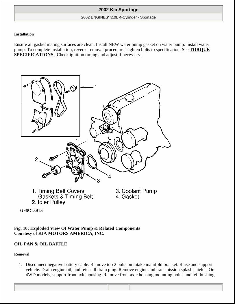
Installation
Ensure all gasket mating surfaces are clean. Install NEW water pump gasket on water pump. Install water pump. To complete installation, reverse removal procedure. Tighten bolts to specification. See TORQUE SPECIFICATIONS . Check ignition timing and adjust if necessary.
Fig. 10: Exploded View Of Water Pump & Related Components Courtesy of KIA MOTORS AMERICA, INC.
OIL PAN & OIL BAFFLE
Removal
1. Disconnect negative battery cable. Remove top 2 bolts on intake manifold bracket. Raise and support vehicle. Drain engine oil, and reinstall drain plug. Remove engine and transmission splash shields. On 4WD models, support front axle housing. Remove front axle housing mounting bolts, and left bushing
2002 Kia Sportage
2002 ENGINES' '2.0L 4-Cylinder - Sportage

from axle housing mount. Carefully lower front axle housing. 2. On 2WD models, remove front left bushing from axle housing mount. Carefully lower front axle housing.
On all models, remove gusset plate mounting bolts from one side of motor, and remove gusset plate. Remove gusset plate mounting bolts from other side of motor, and remove other gusset plate.
3. Remove transmission undercover bolts, and remove engine undercover. Remove oil pan mounting bolts. Separate oil pan from oil baffle and remove oil pan. Remove oil pan. Remove oil strainer assembly. Remove baffle bolt, and remove oil baffle.
Inspection
Remove oil, dirt and sealant from oil pan mounting bolts, oil pan and oil baffle. Inspect oil pan for cracks, deformation and/or damaged drain plug threads. Check oil baffle for damage or cracks. Repair or replace as necessary.
Installation
Apply a continuous bead of silicone sealant along inside of bolt holes of oil baffle and oil pan. Install oil baffle. Install oil baffle mounting bolt. Install oil strainer assembly. Install oil pan. Install oil pan mounting bolts in sequence. See Fig. 16 . Tighten bolts to specification. See TORQUE SPECIFICATIONS . To complete installation, reverse removal procedure.
NOTE: DO NOT bend oil pan or oil baffle while separating, removing or cleaning components.
2002 Kia Sportage
2002 ENGINES' '2.0L 4-Cylinder - Sportage