remoteye viewer, version 9 - onepacs · remoteye viewer, version 9 ... 8.1.2 study-level cine movie...
TRANSCRIPT

RemotEye Viewer, version 9
User Manual

RemotEye Viewer v9: User Manual [RE-V-UM-9 – Rev N]
2
Table of Contents
1 ABBREVIATIONS ................................................................................................................................................... 6
2 INDICATIONS FOR USE ....................................................................................................................................... 6
3 BEFORE YOU BEGIN ............................................................................................................................................ 6
3.1 MINIMUM HARDWARE REQUIREMENTS ................................................................................................................ 7
3.2 SUPPORTED OPERATING SYSTEMS ........................................................................................................................ 7
3.3 SUPPORTED WEB BROWSERS ................................................................................................................................ 8
4 INTRODUCTION .................................................................................................................................................... 8
5 MAIN TOOLBAR .................................................................................................................................................. 11
5.1 HIDE / SHOW MAIN TOOLBAR'S BUTTONS ........................................................................................................... 11
5.2 PATIENTS / STUDIES ........................................................................................................................................... 11
5.3 LOAD ................................................................................................................................................................. 16
5.4 SAVE / EXPORT .................................................................................................................................................. 17
5.4.1 Export files / images to local disk... .......................................................................................................... 17
5.4.1.1 Export DICOM files to local disk ........................................................................................................................... 18
5.4.1.2 Export images in JPG format to local disk .............................................................................................................. 23
5.4.1.3 Export images in PNG format to local disk ............................................................................................................ 24
5.4.1.4 Export images in JPEG-2000 format to local disk .................................................................................................. 25
5.4.1.5 Export series in AVI format to local disk ............................................................................................................... 26
5.4.2 Export files / images to server................................................................................................................... 27
5.4.2.1 Export DICOM files to server ................................................................................................................................. 28
5.4.2.2 Export images in JPG format to server ................................................................................................................... 29
5.4.2.3 Export images in PNG format to server .................................................................................................................. 30
5.4.2.4 Export images in JPEG-2000 format to server ........................................................................................................ 31
5.4.2.5 Export series in AVI format to server ..................................................................................................................... 32
5.4.3 Save user settings ...................................................................................................................................... 33
5.4.4 Copy images to clipboard ......................................................................................................................... 33
5.4.5 CD / DVD creation ................................................................................................................................... 34
5.5 PRINT ................................................................................................................................................................. 35
5.5.1 Normal print... .......................................................................................................................................... 35
5.5.1.1 Content toolbar ....................................................................................................................................................... 36
5.5.1.2 Pages control toolbar .............................................................................................................................................. 38
5.5.1.3 Layout toolbar ......................................................................................................................................................... 38
5.5.2 DICOM print............................................................................................................................................. 41
5.5.2.1 Layout toolbar ......................................................................................................................................................... 42
5.6 SETTINGS... ........................................................................................................................................................ 43
5.6.1 Display preferences .................................................................................................................................. 44

RemotEye Viewer v9: User Manual [RE-V-UM-9 – Rev N]
3
5.6.2 Viewer behaviors ...................................................................................................................................... 46
5.6.3 Text overlays ............................................................................................................................................. 47
5.6.4 Window/Level presets ............................................................................................................................... 52
5.6.5 Hanging protocols .................................................................................................................................... 53
5.6.6 Key bindings ............................................................................................................................................. 63
5.6.7 Local storage preferences ......................................................................................................................... 66
5.6.8 Loading preferences.................................................................................................................................. 67
5.6.9 DICOM printers ........................................................................................................................................ 68
5.7 ONLINE HELP ..................................................................................................................................................... 70
5.8 ABOUT REMOTEYE VIEWER... ........................................................................................................................... 70
6 IMAGE MANIPULATION TOOLBAR .............................................................................................................. 71
6.1 ASSOCIATION OF TOOLS WITH MOUSE BUTTONS ................................................................................................ 72
6.1.1 Select/Stack image .................................................................................................................................... 74
6.1.2 Zoom area ................................................................................................................................................. 74
6.1.3 Magnifier .................................................................................................................................................. 75
6.1.4 Pan image ................................................................................................................................................. 75
6.1.5 Shutter ....................................................................................................................................................... 76
6.1.6 Window / Level .......................................................................................................................................... 76
6.1.7 3D cursor .................................................................................................................................................. 77
6.1.8 Select annotation ....................................................................................................................................... 77
6.1.9 Measurement tools .................................................................................................................................... 78
6.1.9.1 Calibrate measurements .......................................................................................................................................... 78
6.1.9.2 Measure distance .................................................................................................................................................... 79
6.1.9.3 Measure horiz/vert distance .................................................................................................................................... 80
6.1.9.4 Measure distances and angles ................................................................................................................................. 81
6.1.9.5 Measure rect area .................................................................................................................................................... 81
6.1.9.6 Measure ellipt area .................................................................................................................................................. 83
6.1.9.7 Measure angle (mode 1).......................................................................................................................................... 84
6.1.9.8 Measure angle (mode 2).......................................................................................................................................... 84
6.1.9.9 Measure density ...................................................................................................................................................... 85
6.1.10 Line (annotation) ...................................................................................................................................... 86
6.1.11 Poly line (annotation) ............................................................................................................................... 86
6.1.12 Interpolated line (annotation) ................................................................................................................... 87
6.1.13 Free hand (annotation) ............................................................................................................................. 87
6.1.14 Ellipse / Circle (annotation) ..................................................................................................................... 88
6.1.15 Rectangle / Square (annotation) ............................................................................................................... 88
6.1.16 Text (annotation) ...................................................................................................................................... 88
6.1.17 Spine labelling .......................................................................................................................................... 89
6.1.18 Stack image ............................................................................................................................................... 91

RemotEye Viewer v9: User Manual [RE-V-UM-9 – Rev N]
4
6.1.19 Zoom image............................................................................................................................................... 91
6.2 IMAGE OPERATIONS OPTIONS ............................................................................................................................. 92
6.3 RESET OPERATIONS ........................................................................................................................................... 92
6.4 DISPLAY OPTIONS .............................................................................................................................................. 93
6.4.1 Toggle text overlays .................................................................................................................................. 93
6.4.2 Display reference lines ............................................................................................................................. 94
6.4.3 Other display options ................................................................................................................................ 95
6.4.3.1 Mammo CAD markers ............................................................................................................................................ 97
6.4.4 Show image information ......................................................................................................................... 100
6.5 ZOOM OPERATIONS .......................................................................................................................................... 101
6.5.1 Zoom in ................................................................................................................................................... 102
6.5.2 Zoom out ................................................................................................................................................. 102
6.5.3 Zoom to fit ............................................................................................................................................... 102
6.5.4 Zoom reset .............................................................................................................................................. 102
6.6 CONTRAST MANAGEMENT OPERATIONS ........................................................................................................... 102
6.6.1 Invert ....................................................................................................................................................... 103
6.6.2 Auto window ........................................................................................................................................... 103
6.6.3 Apply pseudo-coloring... ......................................................................................................................... 103
6.7 GEOMETRIC TRANSFORMATION OPERATIONS .................................................................................................. 104
6.7.1 Rotate +90° ............................................................................................................................................. 104
6.7.2 Rotate -90° .............................................................................................................................................. 105
6.7.3 Flip horizontally ..................................................................................................................................... 105
6.7.4 Flip vertically .......................................................................................................................................... 105
6.8 KEY IMAGES OPERATIONS ................................................................................................................................ 105
6.8.1 Mark/unmark current image as 'key' image ............................................................................................ 106
6.8.2 View 'key' images in current study .......................................................................................................... 106
6.9 IMAGE ENHANCEMENT OPERATIONS ................................................................................................................ 106
7 REPORTING TOOLBAR ................................................................................................................................... 107
7.1 DICTATE... ....................................................................................................................................................... 107
7.2 CREATE/EDIT DICOM STRUCTURED REPORT .................................................................................................. 109
7.3 VIEW DICOM STRUCTURED REPORT(S)... ...................................................................................................... 110
7.4 LISTEN TO VOICE REPORT... ............................................................................................................................. 112
7.5 PLAIN-TEXT REPORTING .................................................................................................................................. 113
8 STUDY PANELS .................................................................................................................................................. 114
8.1 STUDY TOOLBAR ............................................................................................................................................. 115
8.1.1 MPR (Multi-Planar-Reconstruction) ...................................................................................................... 118
8.1.1.1 MPR 3D view ....................................................................................................................................................... 119
8.1.1.2 MPR 2D views ...................................................................................................................................................... 119

RemotEye Viewer v9: User Manual [RE-V-UM-9 – Rev N]
5
8.1.1.3 MPR main toolbar ................................................................................................................................................. 120
8.1.1.4 Thick slab ............................................................................................................................................................. 121
8.1.2 Study-level cine movie toolbar buttons ................................................................................................... 122
8.1.3 Hanging steps and study view presets ..................................................................................................... 122
8.1.4 Share through Dropbox .......................................................................................................................... 123
9 SERIES PANELS ................................................................................................................................................. 130
9.1 SERIES TOOLBAR ............................................................................................................................................. 130
9.1.1 Series-level cine movie toolbar buttons .................................................................................................. 132
9.2 POP-UP MENU .................................................................................................................................................. 132
10 THUMBNAILS PANEL ................................................................................................................................... 133
11 VIEWER JOBS PANEL .................................................................................................................................. 134
12 HOW TO REPORT ISSUES ........................................................................................................................... 134
13 ACKNOWLEDGMENTS ................................................................................................................................ 135
RemotEye Viewer v9: User Manual [RE-V-UM-9 – Rev N]
6
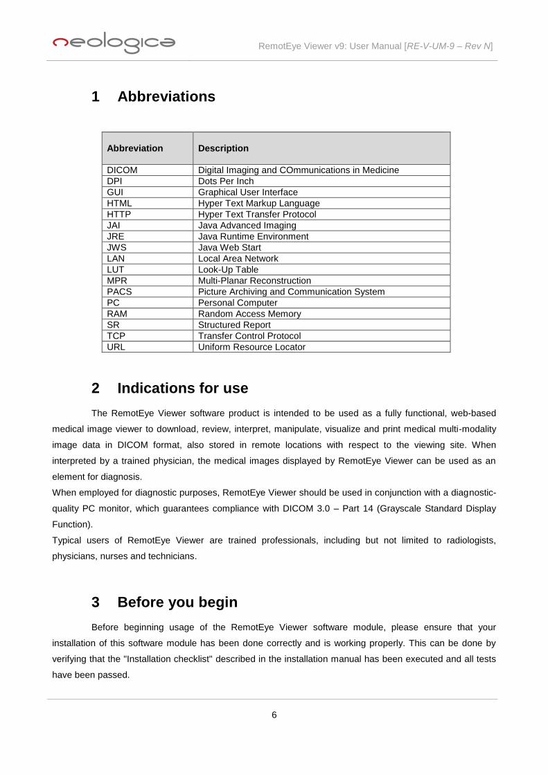
1 Abbreviations
Abbreviation
Description
DICOM Digital Imaging and COmmunications in Medicine
DPI Dots Per Inch
GUI Graphical User Interface
HTML Hyper Text Markup Language
HTTP Hyper Text Transfer Protocol
JAI Java Advanced Imaging
JRE Java Runtime Environment
JWS Java Web Start
LAN Local Area Network
LUT Look-Up Table
MPR Multi-Planar Reconstruction
PACS Picture Archiving and Communication System
PC Personal Computer
RAM Random Access Memory
SR Structured Report
TCP Transfer Control Protocol
URL Uniform Resource Locator
2 Indications for use
The RemotEye Viewer software product is intended to be used as a fully functional, web-based
medical image viewer to download, review, interpret, manipulate, visualize and print medical multi-modality
image data in DICOM format, also stored in remote locations with respect to the viewing site. When
interpreted by a trained physician, the medical images displayed by RemotEye Viewer can be used as an
element for diagnosis.
When employed for diagnostic purposes, RemotEye Viewer should be used in conjunction with a diagnostic-
quality PC monitor, which guarantees compliance with DICOM 3.0 – Part 14 (Grayscale Standard Display
Function).
Typical users of RemotEye Viewer are trained professionals, including but not limited to radiologists,
physicians, nurses and technicians.
3 Before you begin
Before beginning usage of the RemotEye Viewer software module, please ensure that your
installation of this software module has been done correctly and is working properly. This can be done by
verifying that the "Installation checklist" described in the installation manual has been executed and all tests
have been passed.

RemotEye Viewer v9: User Manual [RE-V-UM-9 – Rev N]
7
3.1 Minimum hardware requirements
RemotEye Viewer shall run on a machine based on the x86 or on the x64 (also known as x86-64,
x86_64 or AMD64) CPU architectures. Here is the minimum configuration which is required in order to
ensure RemotEye Viewer will work properly on the client side:
Intel Core i3, 2.5 GHz or faster
4 GB RAM or more
Dedicated graphics adapter, 512 MB video memory or more
Screen with 1280x768 minimum resolution
1 Gb/s Ethernet network adapter
Hard Disk 7200 RPM or faster
50 GB minimum free hard disk space
3.2 Supported operating systems
RemotEye Viewer works on the following Operating Systems:
Microsoft Windows operating systems of the following version:
o Windows Server 2008, 32-bit and 64-bit versions
o Windows Server 2012, 64-bit versions
o Windows 7, 32-bit and 64-bit versions
o Windows 8, 32-bit and 64-bit versions (WARNING: usage on touch screen devices is
NOT supported)
o Windows 10, 32-bit and 64-bit versions (WARNING: usage on touch screen devices is
NOT supported)
Apple Mac OS X of the following versions:
o Mac OS X 10.7.3+, or higher
Linux operating systems of the following versions:
o Oracle Linux 5.5+
o Oracle Linux 6.x (32-bit), 6.x (64-bit)
o Red Hat Enterprise Linux 5.5+, 6.x (32-bit), 6.x (64-bit)
o Ubuntu Linux 10.04 and above
o Suse Linux Enterprise Server 10 SP2, 11.x
RemotEye Viewer v9: User Manual [RE-V-UM-9 – Rev N]
8
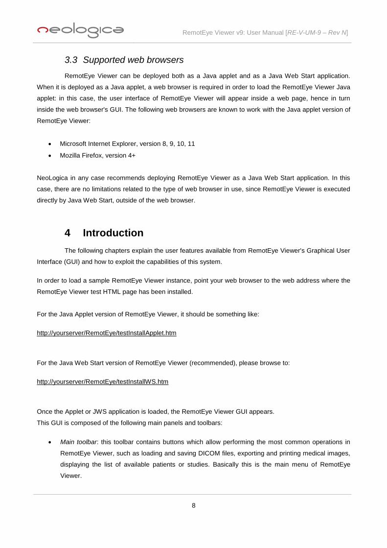
3.3 Supported web browsers
RemotEye Viewer can be deployed both as a Java applet and as a Java Web Start application.
When it is deployed as a Java applet, a web browser is required in order to load the RemotEye Viewer Java
applet: in this case, the user interface of RemotEye Viewer will appear inside a web page, hence in turn
inside the web browser's GUI. The following web browsers are known to work with the Java applet version of
RemotEye Viewer:
Microsoft Internet Explorer, version 8, 9, 10, 11
Mozilla Firefox, version 4+
NeoLogica in any case recommends deploying RemotEye Viewer as a Java Web Start application. In this
case, there are no limitations related to the type of web browser in use, since RemotEye Viewer is executed
directly by Java Web Start, outside of the web browser.
4 Introduction
The following chapters explain the user features available from RemotEye Viewer's Graphical User
Interface (GUI) and how to exploit the capabilities of this system.
In order to load a sample RemotEye Viewer instance, point your web browser to the web address where the
RemotEye Viewer test HTML page has been installed.
For the Java Applet version of RemotEye Viewer, it should be something like:
http://yourserver/RemotEye/testInstallApplet.htm
For the Java Web Start version of RemotEye Viewer (recommended), please browse to:
http://yourserver/RemotEye/testInstallWS.htm
Once the Applet or JWS application is loaded, the RemotEye Viewer GUI appears.
This GUI is composed of the following main panels and toolbars:
Main toolbar: this toolbar contains buttons which allow performing the most common operations in
RemotEye Viewer, such as loading and saving DICOM files, exporting and printing medical images,
displaying the list of available patients or studies. Basically this is the main menu of RemotEye
Viewer.
RemotEye Viewer v9: User Manual [RE-V-UM-9 – Rev N]
9
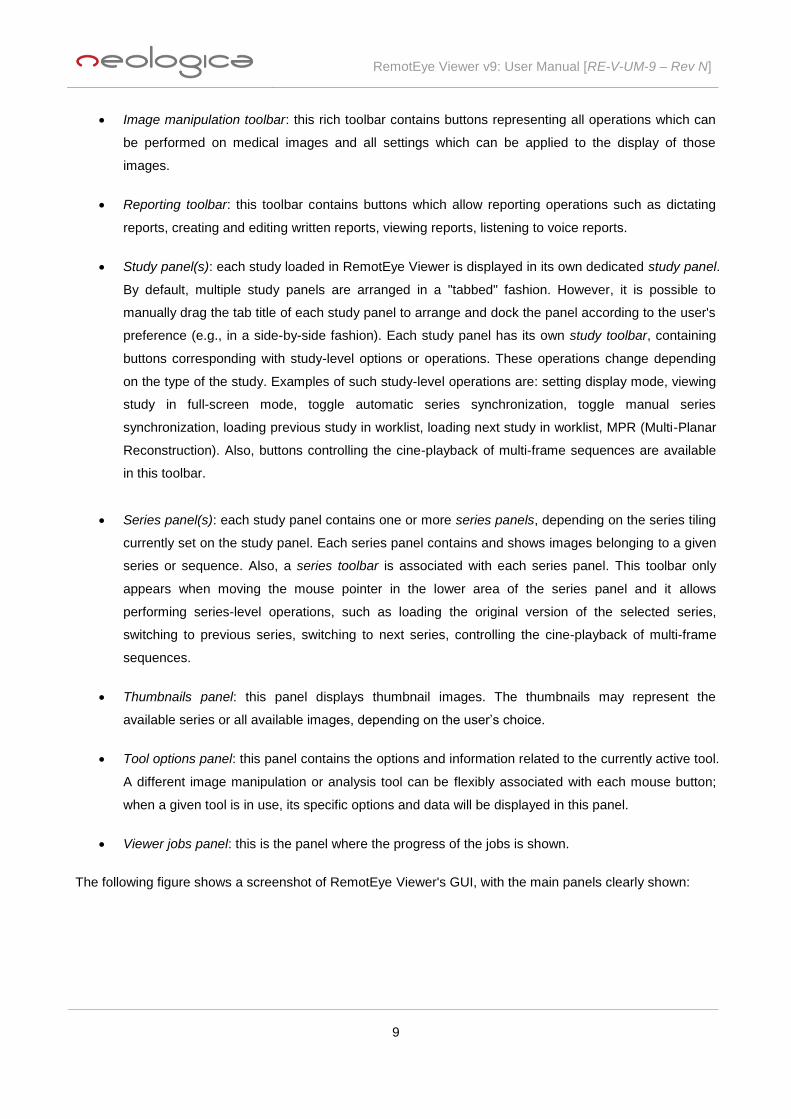
Image manipulation toolbar: this rich toolbar contains buttons representing all operations which can
be performed on medical images and all settings which can be applied to the display of those
images.
Reporting toolbar: this toolbar contains buttons which allow reporting operations such as dictating
reports, creating and editing written reports, viewing reports, listening to voice reports.
Study panel(s): each study loaded in RemotEye Viewer is displayed in its own dedicated study panel.
By default, multiple study panels are arranged in a "tabbed" fashion. However, it is possible to
manually drag the tab title of each study panel to arrange and dock the panel according to the user's
preference (e.g., in a side-by-side fashion). Each study panel has its own study toolbar, containing
buttons corresponding with study-level options or operations. These operations change depending
on the type of the study. Examples of such study-level operations are: setting display mode, viewing
study in full-screen mode, toggle automatic series synchronization, toggle manual series
synchronization, loading previous study in worklist, loading next study in worklist, MPR (Multi-Planar
Reconstruction). Also, buttons controlling the cine-playback of multi-frame sequences are available
in this toolbar.
Series panel(s): each study panel contains one or more series panels, depending on the series tiling
currently set on the study panel. Each series panel contains and shows images belonging to a given
series or sequence. Also, a series toolbar is associated with each series panel. This toolbar only
appears when moving the mouse pointer in the lower area of the series panel and it allows
performing series-level operations, such as loading the original version of the selected series,
switching to previous series, switching to next series, controlling the cine-playback of multi-frame
sequences.
Thumbnails panel: this panel displays thumbnail images. The thumbnails may represent the
available series or all available images, depending on the user’s choice.
Tool options panel: this panel contains the options and information related to the currently active tool.
A different image manipulation or analysis tool can be flexibly associated with each mouse button;
when a given tool is in use, its specific options and data will be displayed in this panel.
Viewer jobs panel: this is the panel where the progress of the jobs is shown.
The following figure shows a screenshot of RemotEye Viewer's GUI, with the main panels clearly shown:

RemotEye Viewer v9: User Manual [RE-V-UM-9 – Rev N]
10
User is able to drag the above mentioned panels and toolbars, to dock them at any side of the main viewer's
window, or to arrange them in a "tabbed" fashion. In this way the Graphical User Interface of RemotEye
Viewer is completely customizable, depending on user's preferences and needs.
The following image shows an example of GUI's customization:

RemotEye Viewer v9: User Manual [RE-V-UM-9 – Rev N]
11
The following sections provide a detailed description of each element of the GUI, as well as of the related
features.
5 Main toolbar
The Main toolbar of RemotEye Viewer acts as its main menu, since it’s the access point to all main
operations and features supported by the viewer.
5.1 Hide / show main toolbar's buttons
This button may be used to hide or show the other Main toolbar's buttons:
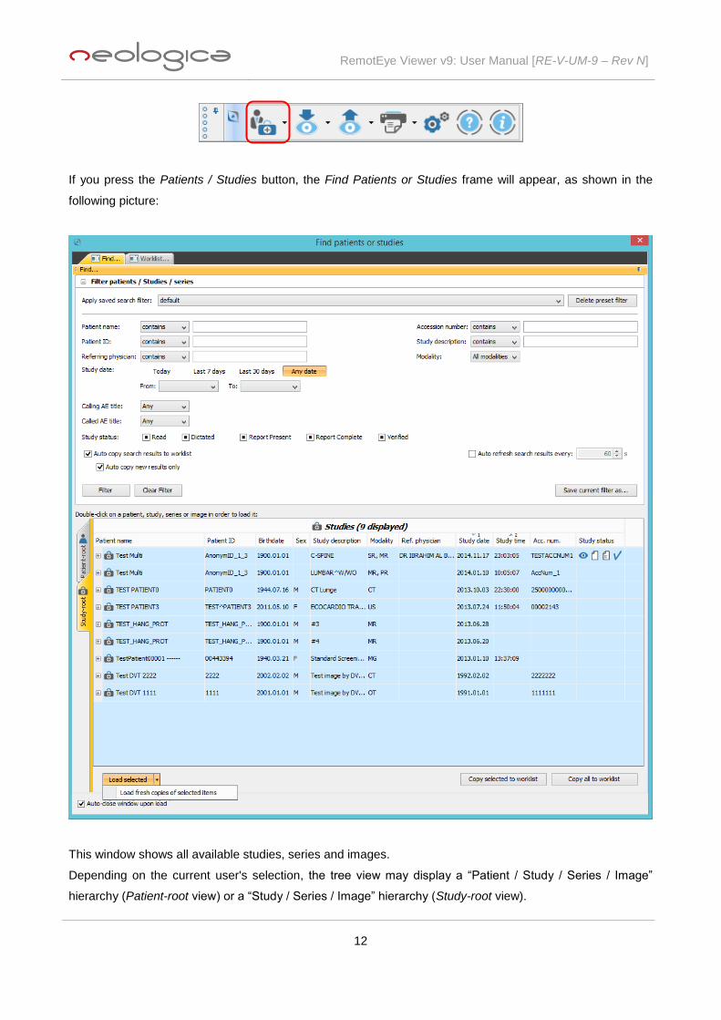
5.2 Patients / Studies
The Patients / Studies toolbar button is shown in the following picture:
RemotEye Viewer v9: User Manual [RE-V-UM-9 – Rev N]
12
If you press the Patients / Studies button, the Find Patients or Studies frame will appear, as shown in the
following picture:
This window shows all available studies, series and images.
Depending on the current user's selection, the tree view may display a “Patient / Study / Series / Image”
hierarchy (Patient-root view) or a “Study / Series / Image” hierarchy (Study-root view).

RemotEye Viewer v9: User Manual [RE-V-UM-9 – Rev N]
13
You can double-click on a patient, study, series or image node (for each operation a massage asks how you
would like to combine the new loaded studies with the existing ones):
Double-clicking on a patient node (only possible with Patient-root view) will cause loading all studies
belonging to that patient. A confirmation for such operation is asked by RemotEye Viewer;
Double-clicking on a study node will cause loading all series belonging to that study;
Double-clicking on a series node will cause loading all images belonging to that series;
Double-clicking on an image node will cause loading just that image.
A powerful search filter is also provided to facilitate the search of a particular patient, study or series.
The user may specify a value for a given search parameter, then press the Filter button: the “Patient / Study /
Series / Image” hierarchy will be filtered and only those nodes matching the search parameter(s) will be
displayed. In particular, the following search parameters are supported:
Patient Name
Patient ID
Referring Physician
Study Date
Study Status (Read, Dictated, Transcribed, Report present, Report complete, Verified - some study
statuses are only available when a specific type of reporting is enabled)
Accession Number
Study Description
Modality
Calling AE Title (only available with the “query” integration model)
Called AE Title (only available with the “query” integration model)
You can apply a previously-saved filter (if any) using the Apply saved search filter option. Also, you can
delete the currently-selected filter, with the Delete preset filter button.
It is possible to clear the currently-set search parameters by pressing the Clear Filter button.
You can also auto-refresh search results (i.e., periodically repeat the query for matching studies), and you
can choose the time of refreshing.
With the Save current filter as... button you can save the current set of search parameters, and assign an
identifying name to this preset.
The Load Selected button allows loading the selected studies; clicking the arrow-shaped drop down button
located next to the Load Selected button, an additional menu containing a Load fresh copies of selected
items functionality will appear, allowing to load fresh copies of the selected studies directly from the server,
without using files eventually present in the local cache. This functionality is useful for instance when some
modifications have occurred on the DICOM data stored on the server, and user wants to acquire the up-to-

RemotEye Viewer v9: User Manual [RE-V-UM-9 – Rev N]
14
date version of those DICOM files (the fresh copies), even if old copies are already present in the local cache
(e.g., due to a previous load operation or background prefetch).
Moreover, the buttons Copy selected to worklist and Copy all to worklist allow copying studies to the
radiologist's worklist (a description of this feature will follow briefly).
Holding down the Ctrl button of the keyboard, you can select several studies at the same time.
If the checkbox Auto-close window upon load is checked, the Find Patients or Studies window will be
automatically closed after a load operation is triggered on this view.
By selecting the Worklist... tab, the radiologist’s worklist view will appear. The Worklist... tab is only available
when the radiologist’s worklist functionality is enabled. The radiologist's worklist is an ordered set of studies
which the current user needs to read, report or review. Studies may be manually added by the user to his
own worklist, either by drag and drop, or by the "Copy..." buttons available under the "Find..." view, or by
checking the "Auto copy search results to worklist" option under the "Find..." view. Checking also the Auto
copy new results only option, only the new results (i.e., results which haven't appeared before in the Find...
view) will be added to the worklist.
For each study, this list shows: Patient Name, Patient ID, Study Description, Modality, Referring Physician,
Study Date, Study Time, Accession Number, Study Status.
RemotEye Viewer v9: User Manual [RE-V-UM-9 – Rev N]
15
Selecting a row and then pressing the arrow-shaped buttons available on the top-right of this view, you can
move a selected study through the list. The same result can be obtained with the mouse, through a
drag&drop operation within the list.
Studies appearing in the worklist may be loaded and displayed by double-clicking on the appropriate row of
the list.
Also, if the checkbox Prefetch worklist studies in background is checked, RemotEye Viewer is able to pre-
fetch in background the studies belonging to the current radiologist’s worklist. Each study is denoted by a
folder icon without tick ( ) if it hasn’t been pre-fetched yet, or a folder icon with tick ( ) if it has already
been pre-fetched. Pre-fetched studies are much faster to load, since they reside on the local hard drive of
the client station.
With the Load selected button you can load the selected study(s); clicking the arrow-shaped drop down
button located next to the Load Selected button, a drop down menu containing a Load fresh copies of
selected items and Clear selected items from cache and prefetch history functionalities will appear. The
former allows the loading of fresh copies of items directly from the server and the latter clears local and back-
end caches from the selected items.
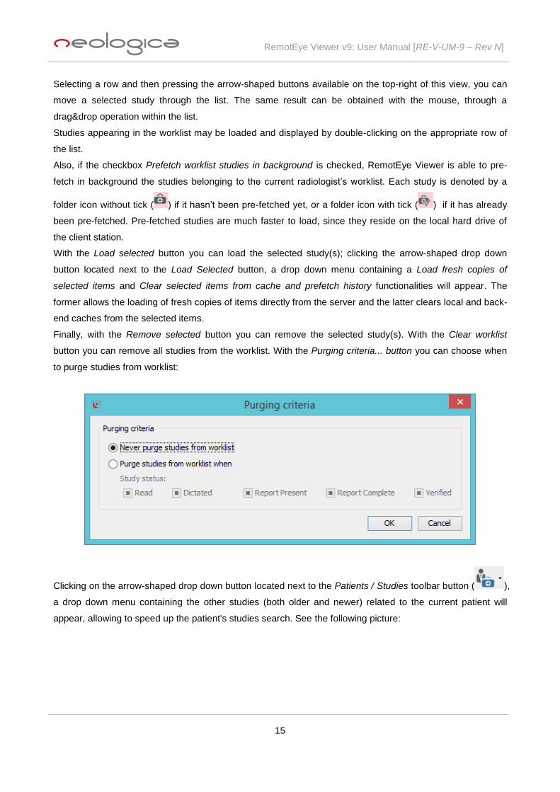
Finally, with the Remove selected button you can remove the selected study(s). With the Clear worklist
button you can remove all studies from the worklist. With the Purging criteria... button you can choose when
to purge studies from worklist:
Clicking on the arrow-shaped drop down button located next to the Patients / Studies toolbar button ( ),
a drop down menu containing the other studies (both older and newer) related to the current patient will
appear, allowing to speed up the patient's studies search. See the following picture:
RemotEye Viewer v9: User Manual [RE-V-UM-9 – Rev N]
16
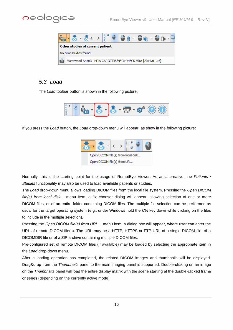
5.3 Load
The Load toolbar button is shown in the following picture:
If you press the Load button, the Load drop-down menu will appear, as show in the following picture:
Normally, this is the starting point for the usage of RemotEye Viewer. As an alternative, the Patients /
Studies functionality may also be used to load available patients or studies.
The Load drop-down menu allows loading DICOM files from the local file system. Pressing the Open DICOM
file(s) from local disk… menu item, a file-chooser dialog will appear, allowing selection of one or more
DICOM files, or of an entire folder containing DICOM files. The multiple-file selection can be performed as
usual for the target operating system (e.g., under Windows hold the Ctrl key down while clicking on the files
to include in the multiple selection).
Pressing the Open DICOM file(s) from URL… menu item, a dialog box will appear, where user can enter the
URL of remote DICOM file(s). The URL may be a HTTP, HTTPS or FTP URL of a single DICOM file, of a
DICOMDIR file or of a ZIP archive containing multiple DICOM files.
Pre-configured set of remote DICOM files (if available) may be loaded by selecting the appropriate item in
the Load drop-down menu.
After a loading operation has completed, the related DICOM images and thumbnails will be displayed.
Drag&drop from the Thumbnails panel to the main imaging panel is supported. Double-clicking on an image
on the Thumbnails panel will load the entire display matrix with the scene starting at the double-clicked frame
or series (depending on the currently active mode).

RemotEye Viewer v9: User Manual [RE-V-UM-9 – Rev N]
17
5.4 Save / Export
The Save / Export toolbar button is shown in the following picture:
If you press the Save / Export button, the Save / Export drop-down menu will appear, as shown in the
following picture:
5.4.1 Export files / images to local disk...
The Export files / images to local disk… menu item can be used to export currently-loaded files /
images to the local file system or to save to the local file system modifications and settings made on images.
If you select the Export files / images to local disk… menu item, the Export files and images to local dialog
box will appear, as shown in the following picture:

RemotEye Viewer v9: User Manual [RE-V-UM-9 – Rev N]
18
Through this dialog, user can select which output format to use for the "export to local disk" operation.
5.4.1.1 Export DICOM files to local disk
The Export DICOM files to local disk page can be displayed by selecting the DICOM format item
from the left-hand list:

RemotEye Viewer v9: User Manual [RE-V-UM-9 – Rev N]
19
This page can be used to export currently-loaded DICOM images to the local file system, or to save to the
local file system modifications and settings made on images, through the Presentation State or Key Object
Selection DICOM objects.
Through this dialog, user can select which series (among the loaded ones) need to be included in the "export
to local" operation.
User can also choose to select all series pressing the Select all series button or to deselect all series
pressing the Deselect all series button.
In addition, you can choose whether DICOM files need to be "anonymized" upon export. If the Anonymize
DICOM files while exporting option is selected, then personal identifying information will be removed from
exported DICOM datasets, according to the currently-set anonymization preferences.
Warning: RemotEye Viewer performs dataset-level anonymization. This means that it is able to clear
or modify the value of the data elements which are present inside the DICOM dataset. RemotEye
Viewer won't clear eventual patient names or other identifying texts which were burnt inside the
image pixels by the modality which generated the DICOM images, since it would be impossible to
automatically and reliably distinguish these texts from the "real" pixel data.
On the Export DICOM files to local disk page, you can choose to export the original DICOM files of the series
which have been selected in the top list. You can also choose whether to create and export new
Presentation States for the selected series. Presentation State objects are able to save and store all settings

RemotEye Viewer v9: User Manual [RE-V-UM-9 – Rev N]
20
performed by the user on the medical images, including contrast settings, rotation, flipping, annotations, etc.
They don’t contain the image, but only the transformations to be applied to images. They are the preferred
way to save all modifications and annotations performed on the displayed DICOM images. Usually, the
Presentation State files are quite small in size, so the store operation is efficient. In addition, you can choose
whether to export the selections of Key Images for the selected series: this option allows supporting
persistence of the Key Image information, which can be maintained the next time the study will be loaded.
When the Export as DICOM button is pressed, a Save file dialog is shown, through which the user will be
able to select the path to be used to save the appropriate DICOM files.
Anonymization preferences
In order to modify the DICOM anonymization preferences, press the Anonymization preferences... button on
the Export DICOM files to local disk page. The Anonymization Preferences dialog box will appear:
Through this dialog, you can choose which DICOM data elements to anonymize, and eventually set a
custom value for each data element:

RemotEye Viewer v9: User Manual [RE-V-UM-9 – Rev N]
21
The custom value of the data element may also include dynamic fields, which are then automatically
substituted by RemotEye Viewer during the anonymization process. The initial values of the "index" dynamic
fields for each export operation may be set in the Advanced settings tab of the Anonymization Preferences
dialog box. Each "index" is meant with reference to the single export operation; it will restart from its initial
value on a subsequent export operation. The Global sequence dynamic field, on the other side, will be
replaced with a new auto-incrementing value each time it will be encountered in the anonymization process,
also within the same DICOM dataset.
If a data element is selected, but no custom value is set for it, then RemotEye Viewer will simply clear the
value of that data element upon export.
In addition to the Standard data elements provided by RemotEye Viewer, the user has the opportunity to add
other data elements which need to be anonymized, through the Other data elements tab of the
Anonymization Preferences dialog box:

RemotEye Viewer v9: User Manual [RE-V-UM-9 – Rev N]
22
Even in this case, the user has the opportunity to eventually set a custom value for each added DICOM data
element, also including dynamic fields.
Finally, the Advanced settings tab allows setting other advanced preferences about the anonymization
process, including whether RemotEye Viewer should generate new unique IDs for the anonymized DICOM
files (recommended), or whether RemotEye Viewer should anonymize all private data elements in the
exported DICOM files.

RemotEye Viewer v9: User Manual [RE-V-UM-9 – Rev N]
23
5.4.1.2 Export images in JPG format to local disk
The Export images in JPG format to local disk page can be displayed by selecting the JPEG format
item from the left-hand list:
RemotEye Viewer v9: User Manual [RE-V-UM-9 – Rev N]
24
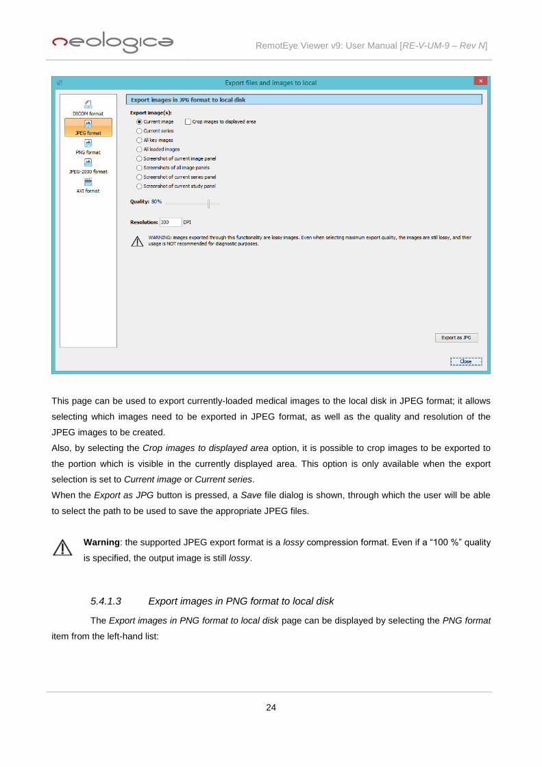
This page can be used to export currently-loaded medical images to the local disk in JPEG format; it allows
selecting which images need to be exported in JPEG format, as well as the quality and resolution of the
JPEG images to be created.
Also, by selecting the Crop images to displayed area option, it is possible to crop images to be exported to
the portion which is visible in the currently displayed area. This option is only available when the export
selection is set to Current image or Current series.
When the Export as JPG button is pressed, a Save file dialog is shown, through which the user will be able
to select the path to be used to save the appropriate JPEG files.
Warning: the supported JPEG export format is a lossy compression format. Even if a “100 %” quality
is specified, the output image is still lossy.
5.4.1.3 Export images in PNG format to local disk
The Export images in PNG format to local disk page can be displayed by selecting the PNG format
item from the left-hand list:

RemotEye Viewer v9: User Manual [RE-V-UM-9 – Rev N]
25
This page can be used to export currently-loaded medical images to the local disk in PNG format; it allows
selecting which images need to be exported in PNG format, as well as the compression level and resolution
of the PNG images to be created
Also, by selecting the Crop images to displayed area option, it is possible to crop images to be exported to
the portion which is visible in the currently displayed area. This option is only available when the export
selection is set to Current image or Current series.
When the Export as PNG button is pressed, a Save file dialog is shown, through which the user will be able
to select the path to be used to save the appropriate PNG files.
5.4.1.4 Export images in JPEG-2000 format to local disk
The Export images in JPEG-2000 format to local disk page can be displayed by selecting the
JPEG-2000 format item from the left-hand list:

RemotEye Viewer v9: User Manual [RE-V-UM-9 – Rev N]
26
This page can be used to export currently-loaded medical images to the local disk in JPEG-2000 format; it
allows selecting which images need to be exported in JPEG-2000 format, as well as the compression type
(Lossless or Lossy) and resolution of the JPEG-2000 images to be created. In case the Lossy compression
type is selected, it is possible to specify the compression level to be used.
Also, by selecting the Crop images to displayed area option, it is possible to crop images to be exported to
the portion which is visible in the currently displayed area. This option is only available when the export
selection is set to Current image or Current series.
When the Export as JPG-2000 button is pressed, a Save file dialog is shown, through which the user will be
able to select the path to be used to save the appropriate JPEG-2000 files.
5.4.1.5 Export series in AVI format to local disk
The Export series in AVI format to local disk page can be displayed by selecting the AVI format
item from the left-hand list:

RemotEye Viewer v9: User Manual [RE-V-UM-9 – Rev N]
27
This page can be used to export currently-loaded series to the local disk in AVI format, as movies; it allows
selecting which series need to be exported in AVI format, as well as quality and frame rate of the AVI movie
to be created.
Also, by selecting the Crop images to displayed area option, it is possible to crop images to be exported to
the portion which is visible in the currently displayed area. This option is only available when the export
selection is set to Current series.
When the Export as AVI button is pressed, a Save file dialog is shown, through which the user will be able to
select the path to be used to save the appropriate AVI files.
5.4.2 Export files / images to server...
The Export files / images to server… menu item can be used to export currently-loaded files /
images to server, or to save to server modifications and settings made on images. This menu item is only
available when RemotEye Viewer is configured to communicate with server-side scripts for the remote
storage operation.
If you select the Export files / images to server… menu item, the Export files and images to server dialog will
appear, as shown in the following picture:
RemotEye Viewer v9: User Manual [RE-V-UM-9 – Rev N]
28
Through this dialog, user can select which format to use for the "export to server" operation.
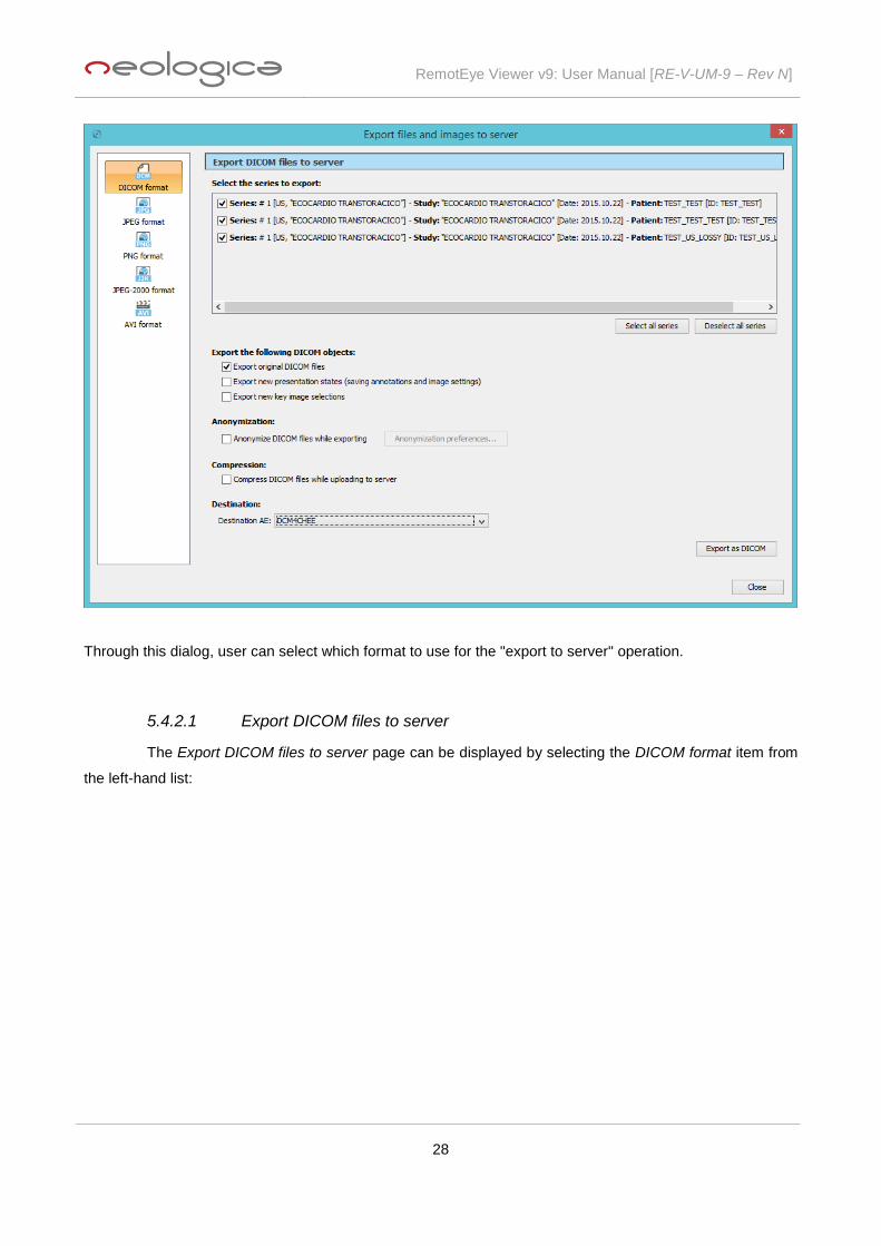
5.4.2.1 Export DICOM files to server
The Export DICOM files to server page can be displayed by selecting the DICOM format item from
the left-hand list:

RemotEye Viewer v9: User Manual [RE-V-UM-9 – Rev N]
29
This page can be used to export currently-loaded DICOM images to server, or to save to server
modifications and settings made on images, through the Presentation State or Key Object Selection DICOM
objects.
The options are exactly the same as explained in the previous paragraph for the Export DICOM files to local
disk functionality. The only difference is that when the Export as DICOM button is pressed, the Save file
dialog is not shown, but DICOM files are automatically saved to the server.
In addition, if the server-side of RemotEye Viewer supports compression, you can choose to compress
DICOM files while uploading them to server. If working on a slow network link (such as an Internet
connection), compression can significantly reduce uploading time.
Finally, if the DICOM back-end supports multiple export AE titles, the Export DICOM files to server window
allows selecting the destination AE title, through a drop-down box.
5.4.2.2 Export images in JPG format to server
The Export images in JPG format to server page can be displayed by selecting the JPEG format
item from the left-hand list.

RemotEye Viewer v9: User Manual [RE-V-UM-9 – Rev N]
30
The options are exactly the same as explained in the previous paragraph for the Export images in JPG
format to local disk functionality. The only difference is that when the Export as JPG button is pressed the
Save file dialog is not shown, but JPEG files are automatically saved to the server.
5.4.2.3 Export images in PNG format to server
The Export images in PNG format to server page can be displayed by selecting the PNG format
item from the left-hand list:

RemotEye Viewer v9: User Manual [RE-V-UM-9 – Rev N]
31
The options are exactly the same as explained in the previous paragraph for the Export images in PNG
format to local disk functionality. The only difference is that when the Export as PNG button is pressed, the
Save file dialog is not shown, but PNG files are automatically saved to the server.
5.4.2.4 Export images in JPEG-2000 format to server
The Export images in JPEG-2000 format to server page can be displayed by selecting the JPEG-
2000 format item from the left-hand list:

RemotEye Viewer v9: User Manual [RE-V-UM-9 – Rev N]
32
The options are exactly the same as explained in the previous paragraph for the Export images in JPEG-
2000 format to local disk functionality. The only difference is that when the Export as JPG-2000 button is
pressed, the Save file dialog is not shown, but JPEG-2000 files are automatically saved to the server.
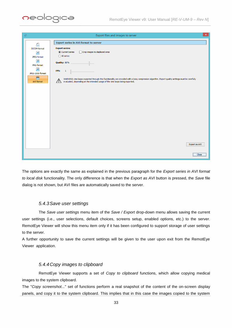
5.4.2.5 Export series in AVI format to server
The Export series in AVI format to server page can be displayed by selecting the AVI format item
from the left-hand list:
RemotEye Viewer v9: User Manual [RE-V-UM-9 – Rev N]
33
The options are exactly the same as explained in the previous paragraph for the Export series in AVI format
to local disk functionality. The only difference is that when the Export as AVI button is pressed, the Save file
dialog is not shown, but AVI files are automatically saved to the server.
5.4.3 Save user settings
The Save user settings menu item of the Save / Export drop-down menu allows saving the current
user settings (i.e., user selections, default choices, screens setup, enabled options, etc.) to the server.
RemotEye Viewer will show this menu item only if it has been configured to support storage of user settings
to the server.
A further opportunity to save the current settings will be given to the user upon exit from the RemotEye
Viewer application.
5.4.4 Copy images to clipboard
RemotEye Viewer supports a set of Copy to clipboard functions, which allow copying medical
images to the system clipboard.
The "Copy screenshot..." set of functions perform a real snapshot of the content of the on-screen display
panels, and copy it to the system clipboard. This implies that in this case the images copied to the system

RemotEye Viewer v9: User Manual [RE-V-UM-9 – Rev N]
34
clipboard have the same size of the related on-screen display panels, hence they are influenced by the
current screen resolution and display mode.
On the other side, the remaining "Copy ... to clipboard" functions copy the medical images to clipboard at
their original size.
The Ctrl+C keyboard shortcut may be used to copy a screenshot of the current image panel to the system
clipboard.
5.4.5 CD / DVD creation
The Save / Export drop-down menu includes a set of menu items which may be used to create
CDs or DVDs containing DICOM images, as well as a dedicated DICOM viewer which will allow displaying
those images on every PC.
Depending on the configuration of RemotEye Viewer, DICOM CDs or DVDs may be created either through
the local CD/DVD writers of the client PC, or on the server side, through a dedicated server software.
In order to create locally a CD or DVD containing the images of the current patient or study, it is sufficient to
select the Burn CD/DVD locally… Burn current Patient or the Burn CD/DVD locally… Burn current
Study menu items.
If the user desires to create CDs or DVDs with a more complex content (e.g., several patients or studies on a
single media) the concept of CD/DVD compilation must be used. The CD/DVD compilation management…
menu contains menu items which allow adding and removing patients and studies from the current CD/DVD
compilation, as well as displaying its current content. Once the CD/DVD compilation is complete, the Burn
CD/DVD locally… Burn content of current CD/DVD compilation menu item can be used to create a CD or
DVD with the content of the current CD/DVD compilation. The Burn DICOM CD/DVD dialog box will appear:

RemotEye Viewer v9: User Manual [RE-V-UM-9 – Rev N]
35
You will need to select the CD/DVD writer to use, through the Select CD/DVD writer drop-down box. Also,
you will be able to choose whether a dedicated DICOM viewer should be included on the CD/DVD, and the
Operating Systems this viewer should be compatible with.
Eventual reports associated with the studies present in the CD/DVD compilation will be included in the
produced CD or DVD, and will be viewable through the embedded DICOM viewer.
Important note: please consider that selecting compatibility of the viewer with multiple Operating
Systems will require more space on the CD/DVD, and more time will be needed to burn the media.
So we suggest enabling compatibility with multiple Operating Systems only if required.
The explained concepts also apply to server-side burning of DICOM CDs or DVDs, when available.
In the case of the Burn DICOM CD/DVD locally functionality, DICOM anonymization is supported: it is
possible to produce CDs or DVDs containing an anonymized (i.e., de-identified) version of the selected
DICOM studies or patients. Please refer to the previous chapter related to DICOM export for details about
the anonymization preferences.
5.5 Print
The Print toolbar button can be used to print medical images to standard PC or network printers, as
well as to specialized DICOM printers (normally, laser film printers). The Print toolbar button is shown in the
following picture:
If you press the Print button, the Print drop-down menu will appear, as shown in the following picture:
5.5.1 Normal print...
In order to print medical images on standard PC or network printers, the Normal print… menu item
must be selected. Once you select the Normal print… menu item, the Print composer panel will appear, as
shown in the following picture:

RemotEye Viewer v9: User Manual [RE-V-UM-9 – Rev N]
36
The Print composer panel provides a real-time and interactive preview of the sheet(s) to be printed. The set
of sheets to be printed will be referred to as the "print booklet" in the following sections. It is possible to
populate the sheets with medical images, as well as to specify several preferences related to the sheets
layout and appearance.
Population of the sheets in the print composer may happen through simple drag&drop operations from the
main image panels, or through more complex operations triggered by toolbar buttons. The print composer is
equipped with 3 toolbars, described in the following sections.
5.5.1.1 Content toolbar
The Content toolbar allows "populating" the sheets to be printed with images, and setting some
common zoom and pan preferences on them.

RemotEye Viewer v9: User Manual [RE-V-UM-9 – Rev N]
37
The Import current screen toolbar button ( ) allows importing all images of the current study panel to the
current sheet in the print booklet. The series tiling currently set on the study panel will also be set as the
layout for the current sheet.
The Import current series toolbar button ( ) allows importing all images of the selected series to the print
booklet. The current layout will be used, and multiple pages will be added if necessary.
The Import current study toolbar button ( ) allows importing all images of the selected study to the print
booklet. The current layout will be used, and multiple pages will be added if necessary.
The Import key images toolbar button ( ) allows importing all images marked as "key" images to the print
booklet. The current layout will be used, and multiple pages will be added if necessary.
When using the mouse on a sheet of the print booklet, special functions are associated with the mouse
buttons. In particular, the "Pan" tool is associated with the left mouse button, as reminded by the icon
appearing on top of the content toolbar. Thus, left-dragging on an image contained in a sheet of the print
booklet will pan that image, if it was previously zoomed in.
The "Zoom" tool is associated with the mouse wheel, as reminded by the icon appearing on top of the
content toolbar. Thus, scrolling the mouse wheel will zoom in and out the selected image of the current sheet.
Finally, double-clicking the right mouse button will reset the selected image of the current sheet to its default
zoom (to fit) and pan.
RemotEye Viewer v9: User Manual [RE-V-UM-9 – Rev N]
38
The All views as selected (current sheet) toolbar button ( ) allows applying the zoom and pan of the
current image box to all image boxes of the current sheet.
The All views as selected (all sheets) toolbar button ( ) allows applying the zoom and pan of the current
image box to all image boxes of all sheets in the booklet.
User can also drag&drop images from the main image panels to the current sheet of the print booklet. Also,
pressing the Canc button on the keyboard, it is possible to remove a selected image from the sheet.
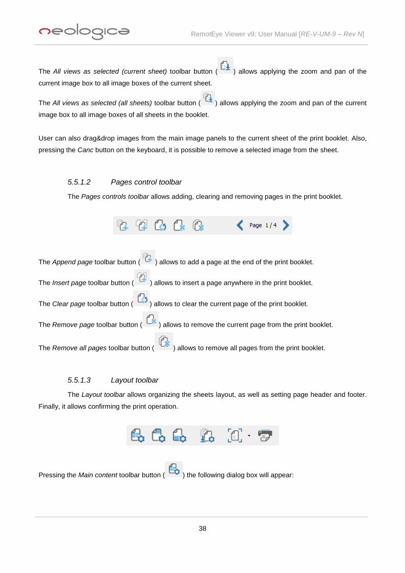
5.5.1.2 Pages control toolbar
The Pages controls toolbar allows adding, clearing and removing pages in the print booklet.
The Append page toolbar button ( ) allows to add a page at the end of the print booklet.
The Insert page toolbar button ( ) allows to insert a page anywhere in the print booklet.
The Clear page toolbar button ( ) allows to clear the current page of the print booklet.
The Remove page toolbar button ( ) allows to remove the current page from the print booklet.
The Remove all pages toolbar button ( ) allows to remove all pages from the print booklet.
5.5.1.3 Layout toolbar
The Layout toolbar allows organizing the sheets layout, as well as setting page header and footer.
Finally, it allows confirming the print operation.
Pressing the Main content toolbar button ( ) the following dialog box will appear:

RemotEye Viewer v9: User Manual [RE-V-UM-9 – Rev N]
39
The Image display format drop down menu allows choosing the image layout (1x1, 2x2, 3x2, 3x3, etc.) for
the current sheet:
The Sheet background drop down menu allows selecting the background colour of the current sheet (Black
or White):
Pressing the Page header toolbar button ( ) the following dialog box will appear:

RemotEye Viewer v9: User Manual [RE-V-UM-9 – Rev N]
40
It is possible to include an image in the header of each sheet of the print booklet, by checking the Enable
printing of a header image checkbox. User will be able to choose the pathname and the height of the header
image.
Also, it is possible to include a text string in the header of each sheet of the print booklet, by checking the
Enable printing of a header text checkbox. User will be able to insert a header text or, with the Insert dyn
field... drop down menu, a dynamic field which will be automatically substituted by RemotEye Viewer with
appropriate values before the actual printing takes place.
With the Font and Color drop down menus user can select, respectively, font and color of the header text:
Pressing the Page footer toolbar button ( ) a dialog box identical with the Page header dialog box will
appear, allowing the same operations.
The Apply attributes to all pages toolbar button ( ) allows applying the layout and appearance (including
header, footer, background, etc.) of the current page to all pages of the print booklet.
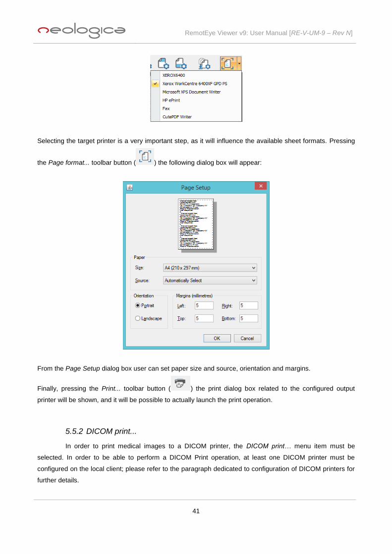
The Page format... drop down menu allows selecting the target printer for the print operation:
RemotEye Viewer v9: User Manual [RE-V-UM-9 – Rev N]
41
Selecting the target printer is a very important step, as it will influence the available sheet formats. Pressing
the Page format... toolbar button ( ) the following dialog box will appear:
From the Page Setup dialog box user can set paper size and source, orientation and margins.
Finally, pressing the Print... toolbar button ( ) the print dialog box related to the configured output
printer will be shown, and it will be possible to actually launch the print operation.
5.5.2 DICOM print...
In order to print medical images to a DICOM printer, the DICOM print… menu item must be
selected. In order to be able to perform a DICOM Print operation, at least one DICOM printer must be
configured on the local client; please refer to the paragraph dedicated to configuration of DICOM printers for
further details.

RemotEye Viewer v9: User Manual [RE-V-UM-9 – Rev N]
42
Once you select the DICOM print… menu item, the Print composer panel will appear, as shown in the
following picture:
The Print composer panel provides a real-time and interactive preview of the sheet(s) to be printed. The set
of sheets to be printed will be referred to as the "print booklet" in the following sections. It is possible to
populate the sheets with medical images, as well as to specify several preferences related to the sheets
layout and appearance.
Population of the sheets in the print composer may happen through simple drag&drop operations from the
main image panels, or through more complex operations triggered by toolbar buttons. The print composer is
equipped with 3 toolbars: the content toolbar, the pages control toolbar and the layout toolbar. While the
content toolbar and the pages control toolbar are identical with the ones described above for the normal print
functionality (see previous paragraphs for an explanation), the layout toolbar is significantly different in case
of DICOM print.
5.5.2.1 Layout toolbar
The Layout toolbar, in case of DICOM print, allows setting the layout and appearance of the sheets
of the print booklet.

RemotEye Viewer v9: User Manual [RE-V-UM-9 – Rev N]
43
Pressing the Main content toolbar button ( ) the Film Box attributes panel will appear; user is able to set
up DICOM attributes from here:
The Image display format drop down menu allows choosing the image layout (1x1, 2x2, 3x2, 3x3, etc.) for
the current sheet:
In addition, the Film Box attributes panel will also allow setting all other sheet-level attributes and
preferences which are defined by the DICOM standard, for the DICOM print operation.
The Apply attributes to all pages toolbar button ( ) allows applying the layout and appearance of the
current page to all pages of the print booklet.
Finally, pressing the Print... toolbar button ( ) the print dialog box related to the configured output
DICOM printer will be shown, and it will be possible to actually launch the DICOM print operation.
5.6 Settings...
The Settings… toolbar button can be used to configure several aspects of RemotEye Viewer,
including hanging protocols, DICOM printers, display preferences and storage preferences.

RemotEye Viewer v9: User Manual [RE-V-UM-9 – Rev N]
44
This toolbar button is shown in the following picture:
Pressing the Settings… button, the Settings dialog-box will appear:
In some cases (e.g. modifications in screens configuration, font size, icons size, etc.), it is necessary to save
user settings and to restart RemotEye Viewer in order to allow modifications to take effect.
5.6.1 Display preferences
RemotEye Viewer allows configuring several display preferences, mainly related to multi-monitor
configurations.

RemotEye Viewer v9: User Manual [RE-V-UM-9 – Rev N]
45
The Display preferences page can be displayed by selecting the Display preferences item from the left-hand
list.
This configuration page allows specifying the default font size and icons size for RemotEye Viewer’s GUI:
Medium and Large sizes are recommended for high-resolution monitors, while a Small and X-Small sizes
should be fine with a standard PC monitor; it is also allowed to show markers ( ) of on-screen images on
thumbnails, to show marker ( ) of selected image on thumbnails and to synchronize thumbnail selection
with image selection on main panel.
In addition, in case of multi-monitor display systems, it is possible to specify on which screen(s) the image
viewer windows, the Patients/Studies window and the reporting windows shall be shown.
Some other display-related preferences can also be set through this configuration page.

RemotEye Viewer v9: User Manual [RE-V-UM-9 – Rev N]
46
5.6.2 Viewer behaviors
RemotEye Viewer allows configuring several viewer behaviours related to Study loading, Study
closing, Frame scrolling, Synchronized scrolling, Cine loops, Viewing series splitting criteria and Saving
settings on exit.
The Viewer behaviors page can be displayed by selecting the Viewer behaviors item from the left-hand list.
RemotEye Viewer v9: User Manual [RE-V-UM-9 – Rev N]
47
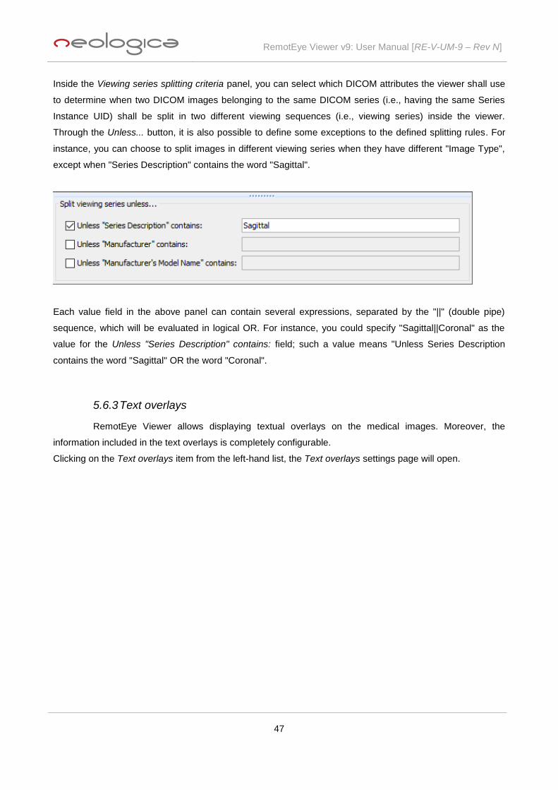
Inside the Viewing series splitting criteria panel, you can select which DICOM attributes the viewer shall use
to determine when two DICOM images belonging to the same DICOM series (i.e., having the same Series
Instance UID) shall be split in two different viewing sequences (i.e., viewing series) inside the viewer.
Through the Unless... button, it is also possible to define some exceptions to the defined splitting rules. For
instance, you can choose to split images in different viewing series when they have different "Image Type",
except when "Series Description" contains the word "Sagittal".
Each value field in the above panel can contain several expressions, separated by the "||" (double pipe)
sequence, which will be evaluated in logical OR. For instance, you could specify "Sagittal||Coronal" as the
value for the Unless "Series Description" contains: field; such a value means "Unless Series Description
contains the word "Sagittal" OR the word "Coronal".
5.6.3 Text overlays
RemotEye Viewer allows displaying textual overlays on the medical images. Moreover, the
information included in the text overlays is completely configurable.
Clicking on the Text overlays item from the left-hand list, the Text overlays settings page will open.

RemotEye Viewer v9: User Manual [RE-V-UM-9 – Rev N]
48
This page shows a list of all textual overlays which are currently configured in RemotEye Viewer. Each
overlay is identified by a description and a set of matching criteria. For example, text overlays related to MR
modality are displayed only on MR images. As detailed in the following, different parameters are settable in
order to define proper matching criteria to be used for each text overlay. In addition, selecting the High-
quality delayed rendering of text overlays checkbox, high-quality, high-contrast, anti-aliased rendering of the
text strings related to overlays will be enabled. The painting of this high-quality overlay only happens when
the image is in idle state for a couple of seconds (i.e., it is "delayed"), in order not to cause performance
penalties in the viewer.
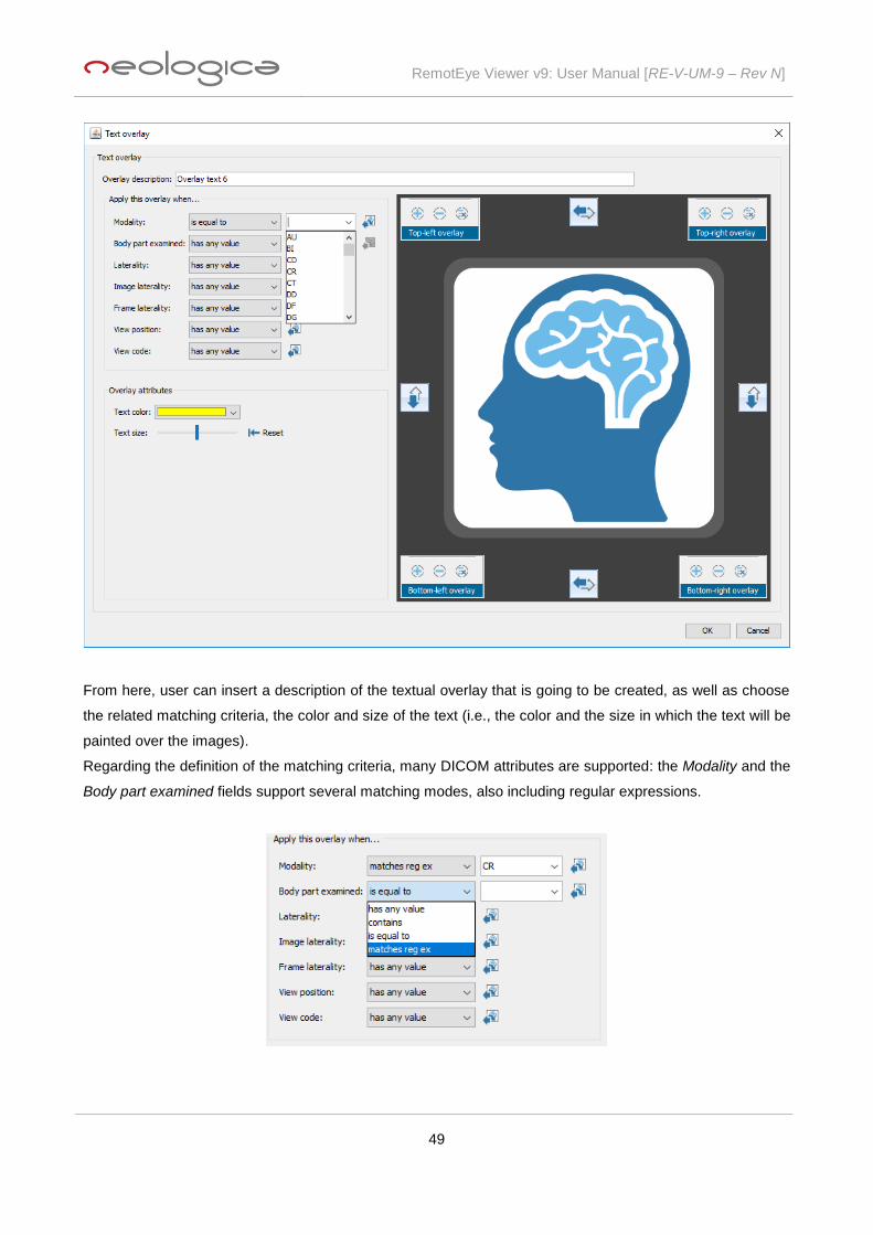
In order to create a new textual overlay, user has to click on the Add text overlay button, and the following
dialog box will appear:
RemotEye Viewer v9: User Manual [RE-V-UM-9 – Rev N]
49
From here, user can insert a description of the textual overlay that is going to be created, as well as choose
the related matching criteria, the color and size of the text (i.e., the color and the size in which the text will be
painted over the images).
Regarding the definition of the matching criteria, many DICOM attributes are supported: the Modality and the
Body part examined fields support several matching modes, also including regular expressions.

RemotEye Viewer v9: User Manual [RE-V-UM-9 – Rev N]
50
Laterality, Image laterality, Frame laterality, View position and View code are other fields whose value can be
chosen from a predetermined list.
Using the appropriate overlay areas placed at the corners of the image panel prototype, user can decide
which information to display, and where to show it.
Clicking on the button located in each corner, a new overlay text line will be added in that corner of the
image, and the following dialog will appear:
From here, it is possible to choose which overlay field to insert in the specific text line. User can give a
description of the overlay line using the appropriate Overlay line description field. In addition, he can decide
whether the line can be hidden or not, and if it is allowed to wrap across several lines, when its length is such
that it cannot completely fit into a single line.
Clicking on the button, user can add a new field to the current overlay text line. Once the field is selected
with a mouse click, user can choose the type of overlay field. Selecting the Free text option, user can insert a
fixed free text in the appropriate space. Clicking on the DICOM attribute option, user can choose a specific
DICOM attribute to display (e.g., DICOM: (0010,0010) - Patient’s Name). While, selecting the Other dynamic
field option, a drop-down menu will appear, allowing user to choose the desired dynamic field (e.g., zoom
RemotEye Viewer v9: User Manual [RE-V-UM-9 – Rev N]
51
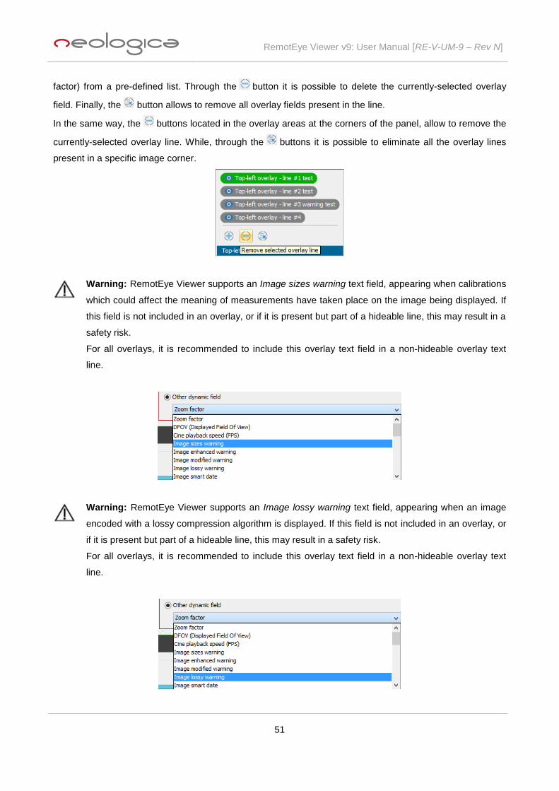
factor) from a pre-defined list. Through the button it is possible to delete the currently-selected overlay
field. Finally, the button allows to remove all overlay fields present in the line.
In the same way, the buttons located in the overlay areas at the corners of the panel, allow to remove the
currently-selected overlay line. While, through the buttons it is possible to eliminate all the overlay lines
present in a specific image corner.
Warning: RemotEye Viewer supports an Image sizes warning text field, appearing when calibrations
which could affect the meaning of measurements have taken place on the image being displayed. If
this field is not included in an overlay, or if it is present but part of a hideable line, this may result in a
safety risk.
For all overlays, it is recommended to include this overlay text field in a non-hideable overlay text
line.
Warning: RemotEye Viewer supports an Image lossy warning text field, appearing when an image
encoded with a lossy compression algorithm is displayed. If this field is not included in an overlay, or
if it is present but part of a hideable line, this may result in a safety risk.
For all overlays, it is recommended to include this overlay text field in a non-hideable overlay text
line.

RemotEye Viewer v9: User Manual [RE-V-UM-9 – Rev N]
52
Finally, user may take advantage of the ‘switch’ buttons located at the Text overlay panel’s sides to
switch the position on the panel of the relating text overlays.
5.6.4 Window/Level presets
RemotEye Viewer supports definition of contrast presets through the GUI. The Window/Level
presets page, showing the contrast presets currently defined for the present user, can be displayed by
selecting the Window/Level presets item from the left-hand list.
In order to create a new contrast preset, press the Add preset button, located at the bottom of the
Window/Level presets configuration page. A new Window/Level Preset dialog box will appear, as show in the
picture below.
RemotEye Viewer v9: User Manual [RE-V-UM-9 – Rev N]
53
This dialog allows specifying the Description (i.e., identifying name appearing on the GUI) for this
Window/Level Preset, as well as the Modality, Window Width and Window Level data. If you select a specific
Modality when building the preset, then this Window/Level preset will only be available when images of that
modality are selected. Finally, user can set a keyboard shortcut through which it will be possible to easily
invoke application of that specific Window/Level preset.
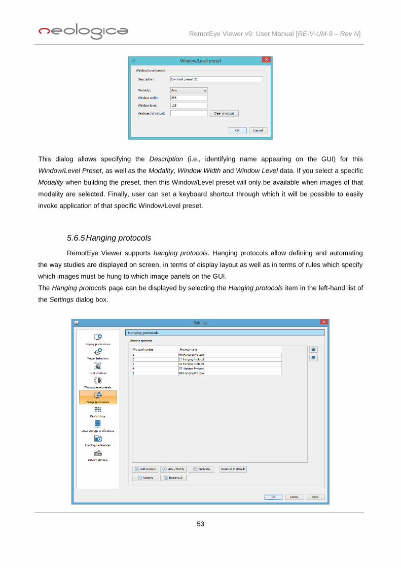
5.6.5 Hanging protocols
RemotEye Viewer supports hanging protocols. Hanging protocols allow defining and automating
the way studies are displayed on screen, in terms of display layout as well as in terms of rules which specify
which images must be hung to which image panels on the GUI.
The Hanging protocols page can be displayed by selecting the Hanging protocols item in the left-hand list of
the Settings dialog box.
RemotEye Viewer v9: User Manual [RE-V-UM-9 – Rev N]
54
This window shows all hanging protocols currently defined for the present user. Each hanging protocol is
identified by a protocol name, which shall be unique.
When a study is loaded, for instance by double-clicking on a study node in the Patients/Studies window, a
check on all available hanging protocols is made. The first matching hanging protocol (if any) will be
automatically applied upon loading of the study. The user will then be able to apply other hanging views of
other matching hanging protocols once the study will be displayed on screen.
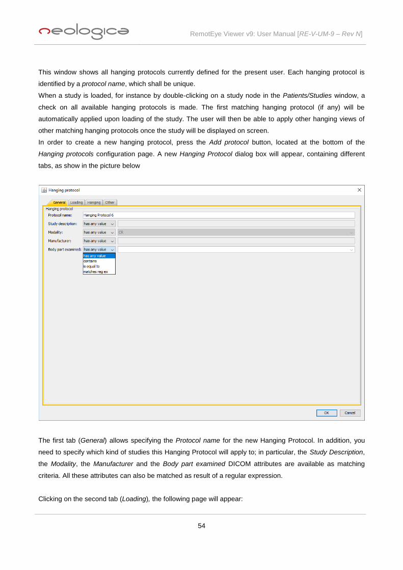
In order to create a new hanging protocol, press the Add protocol button, located at the bottom of the
Hanging protocols configuration page. A new Hanging Protocol dialog box will appear, containing different
tabs, as show in the picture below
The first tab (General) allows specifying the Protocol name for the new Hanging Protocol. In addition, you
need to specify which kind of studies this Hanging Protocol will apply to; in particular, the Study Description,
the Modality, the Manufacturer and the Body part examined DICOM attributes are available as matching
criteria. All these attributes can also be matched as result of a regular expression.
Clicking on the second tab (Loading), the following page will appear:

RemotEye Viewer v9: User Manual [RE-V-UM-9 – Rev N]
55
From here, it is possible to instruct RemotEye Viewer to automatically also load prior studies when loading a
study, by selecting the related checkboxes. In particular, RemotEye Viewer allows choosing whether to
automatically load also the first, the second, the third and/or the fourth prior studies, upon loading a study
which matches this hanging protocol. The first prior study is the most recent study, prior to the selected one,
matching the criteria of the current hanging protocol. In the same way, the second, the third and the fourth
prior studies are the second, the third and the fourth most recent studies, prior to the selected one, matching
the criteria of the current hanging protocol. The Prior studies options are particularly useful when one wishes
to automate comparisons of exams taken by a given patient over time.
Clicking on the Hanging tab, the following page will be open:

RemotEye Viewer v9: User Manual [RE-V-UM-9 – Rev N]
56
From here, user can specify the hanging preferences which will be associated with this hanging protocol,
hence will be applied upon loading a study which matches this hanging protocol.
The Hanging section of the hanging protocol configuration interface allows defining exactly how studies and
series shall be presented on screen upon study load. Moreover, this section allows defining several "hanging
steps" within each hanging protocol. While viewing a study, it will be possible for the user to easily iterate
through all "hanging steps" which are present within the hanging protocol, in a next/previous fashion, as
shown in the following image:
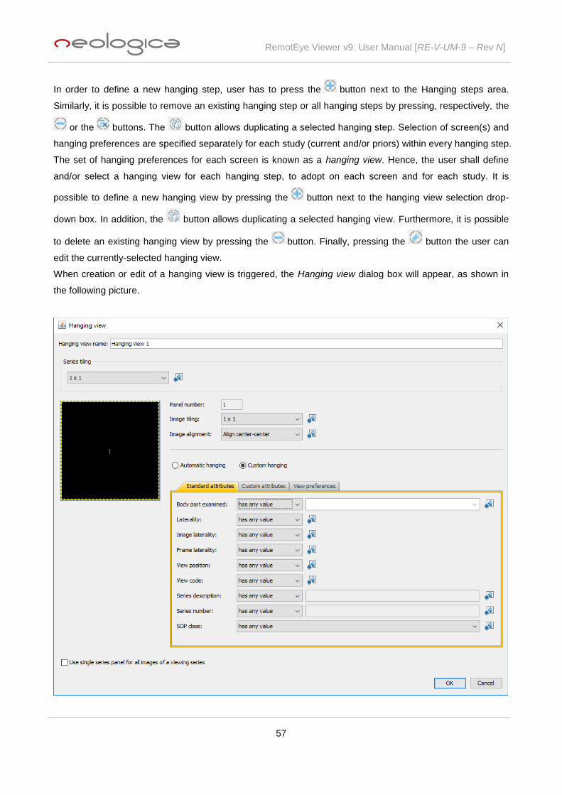
RemotEye Viewer v9: User Manual [RE-V-UM-9 – Rev N]
57
In order to define a new hanging step, user has to press the button next to the Hanging steps area.
Similarly, it is possible to remove an existing hanging step or all hanging steps by pressing, respectively, the
or the buttons. The button allows duplicating a selected hanging step. Selection of screen(s) and
hanging preferences are specified separately for each study (current and/or priors) within every hanging step.
The set of hanging preferences for each screen is known as a hanging view. Hence, the user shall define
and/or select a hanging view for each hanging step, to adopt on each screen and for each study. It is
possible to define a new hanging view by pressing the button next to the hanging view selection drop-
down box. In addition, the button allows duplicating a selected hanging view. Furthermore, it is possible
to delete an existing hanging view by pressing the button. Finally, pressing the button the user can
edit the currently-selected hanging view.
When creation or edit of a hanging view is triggered, the Hanging view dialog box will appear, as shown in
the following picture.

RemotEye Viewer v9: User Manual [RE-V-UM-9 – Rev N]
58
A description of each parameter of the hanging view follows:
o Hanging view name: the unique identifying name of the hanging view.
o Series tiling: the series tiling (i.e., series columns and series rows) to apply on the study
panel where the study will be hung.
o Image tiling: it allows specifying the image tiling for each series panel. The image tiling
determines how many images of that series will be concurrently visible in a specific series
panel.
o Image alignment.
o Automatic hanging: series will be hung automatically by the software in the target study
panel.
o Custom hanging: the user is able to specify hanging rules for each panel of the chosen
display layout: upon study load, the series which first matches the hanging rule for a given
series panel will be displayed in that series panel. By selecting the Custom hanging option,
three different tabs will be activated:
Standard attributes: the main and most-commonly used DICOM attributes for a
hanging rule can be set in this tab. Here are the supported standard attributes:
Body Part Examined
Laterality
Image Laterality
View Position
View Code
Series Description
Series Number
SOP Class
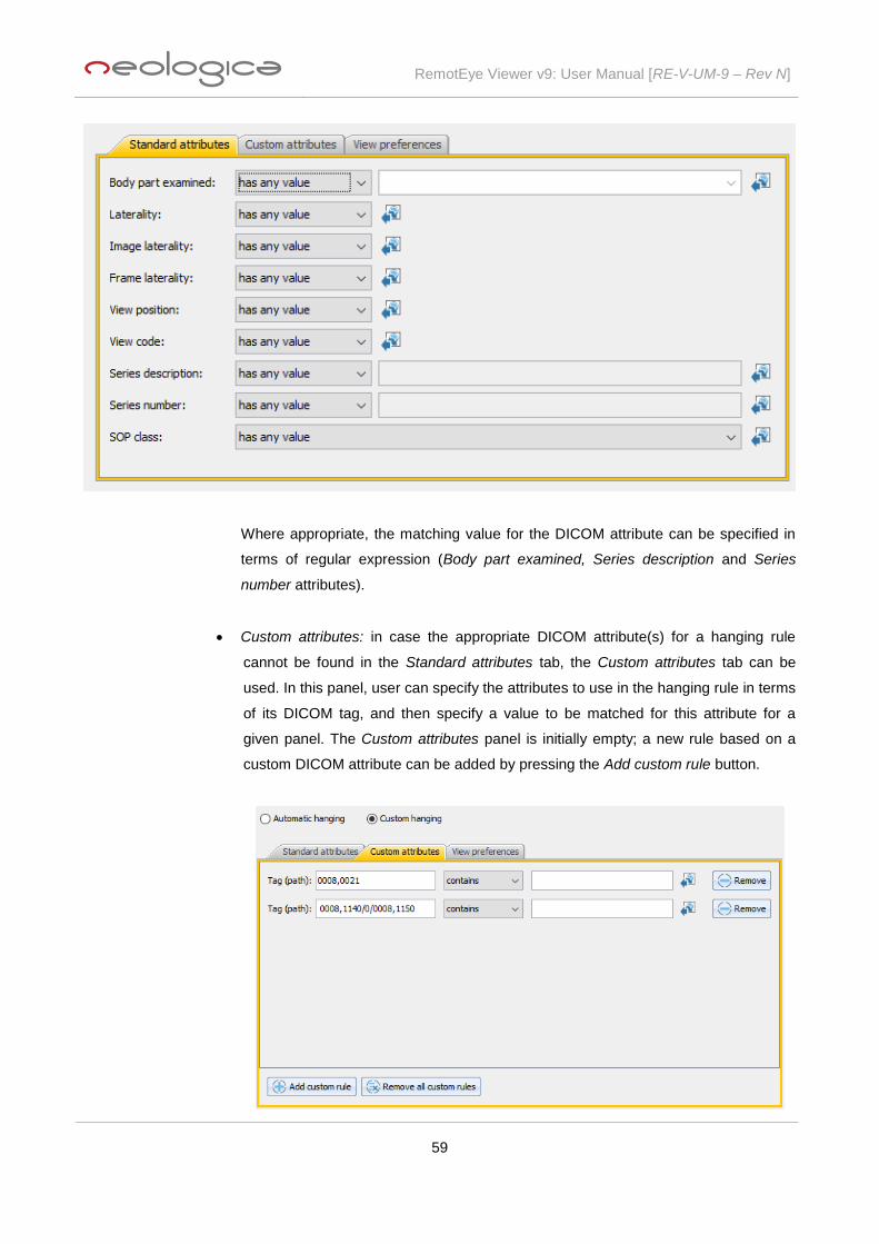
RemotEye Viewer v9: User Manual [RE-V-UM-9 – Rev N]
59
Where appropriate, the matching value for the DICOM attribute can be specified in
terms of regular expression (Body part examined, Series description and Series
number attributes).
Custom attributes: in case the appropriate DICOM attribute(s) for a hanging rule
cannot be found in the Standard attributes tab, the Custom attributes tab can be
used. In this panel, user can specify the attributes to use in the hanging rule in terms
of its DICOM tag, and then specify a value to be matched for this attribute for a
given panel. The Custom attributes panel is initially empty; a new rule based on a
custom DICOM attribute can be added by pressing the Add custom rule button.

RemotEye Viewer v9: User Manual [RE-V-UM-9 – Rev N]
60
As you can see in the above image, any DICOM data element existing in a DICOM
dataset can be reached by means of a proper syntax: if it is a “root” element, a
single DICOM tag is sufficient to identify the attribute (as in the first row in the image
above). A “non-root” data element of a DICOM dataset can also be reached, by
means of a path-like syntax, as shown in the second row in the image above.
View preferences: tab containing further options related to how images shall be
presented for each series panel. Supported options are:
Zoom / Pan
Orientation (top side of image): the user can force the orientation for the top
side of the image. The viewer will automatically rotate and/or flip the image,
if necessary, in an effort to obtain the desired orientation for the top side of
the image.
Orientation (left side of image): the user can force the orientation for the left
side of the image. The viewer will automatically rotate and/or flip the image,
if necessary, in an effort to obtain the desired orientation for the left side of
the image.
The Import from corresponding image/panel buttons placed next to each matching attribute allow
automatically importing the value of each attribute from the selected image/panel.

RemotEye Viewer v9: User Manual [RE-V-UM-9 – Rev N]
61
In addition, near the Zoom / Pan button a Reset button is present, allowing to reset the current Zoom /
Pan value.
If desired, the image hanging process can use single series panel for all images of a viewing series selecting
the proper checkbox. If this option is not selected, the viewer will treat each single image independently, and
will hang it to the first "free" series panel for which the hanging rules are matched.
After the definition of the hanging view(s), the user can define exactly “where” the study panel (laid out
according to the hanging view) shall be located within the screen, by acting on the docking properties:
Moreover, the user can add actions associated with each hanging step, through the Associated actions tab
(see picture below). These actions will be automatically executed by the viewer when the related hanging
step will be invoked by the user:
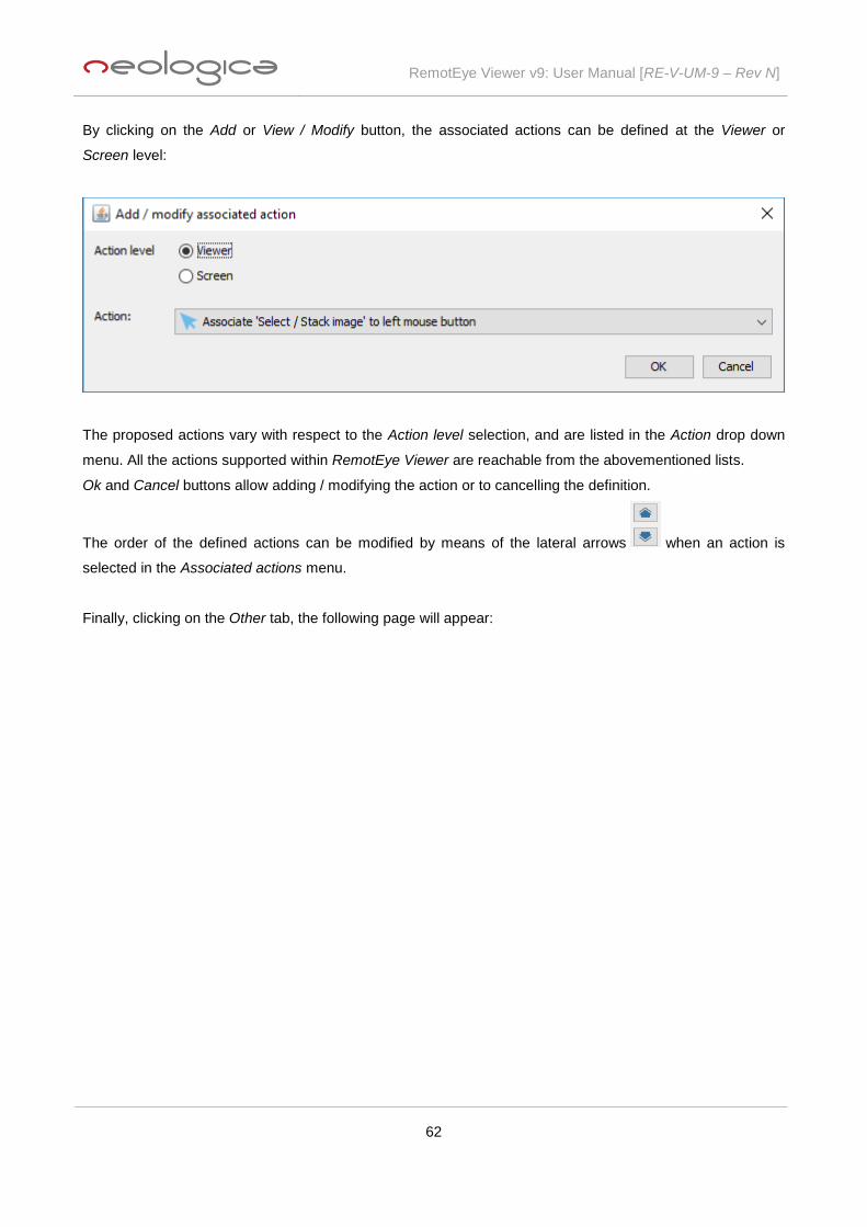
RemotEye Viewer v9: User Manual [RE-V-UM-9 – Rev N]
62
By clicking on the Add or View / Modify button, the associated actions can be defined at the Viewer or
Screen level:
The proposed actions vary with respect to the Action level selection, and are listed in the Action drop down
menu. All the actions supported within RemotEye Viewer are reachable from the abovementioned lists.
Ok and Cancel buttons allow adding / modifying the action or to cancelling the definition.
The order of the defined actions can be modified by means of the lateral arrows when an action is
selected in the Associated actions menu.
Finally, clicking on the Other tab, the following page will appear:
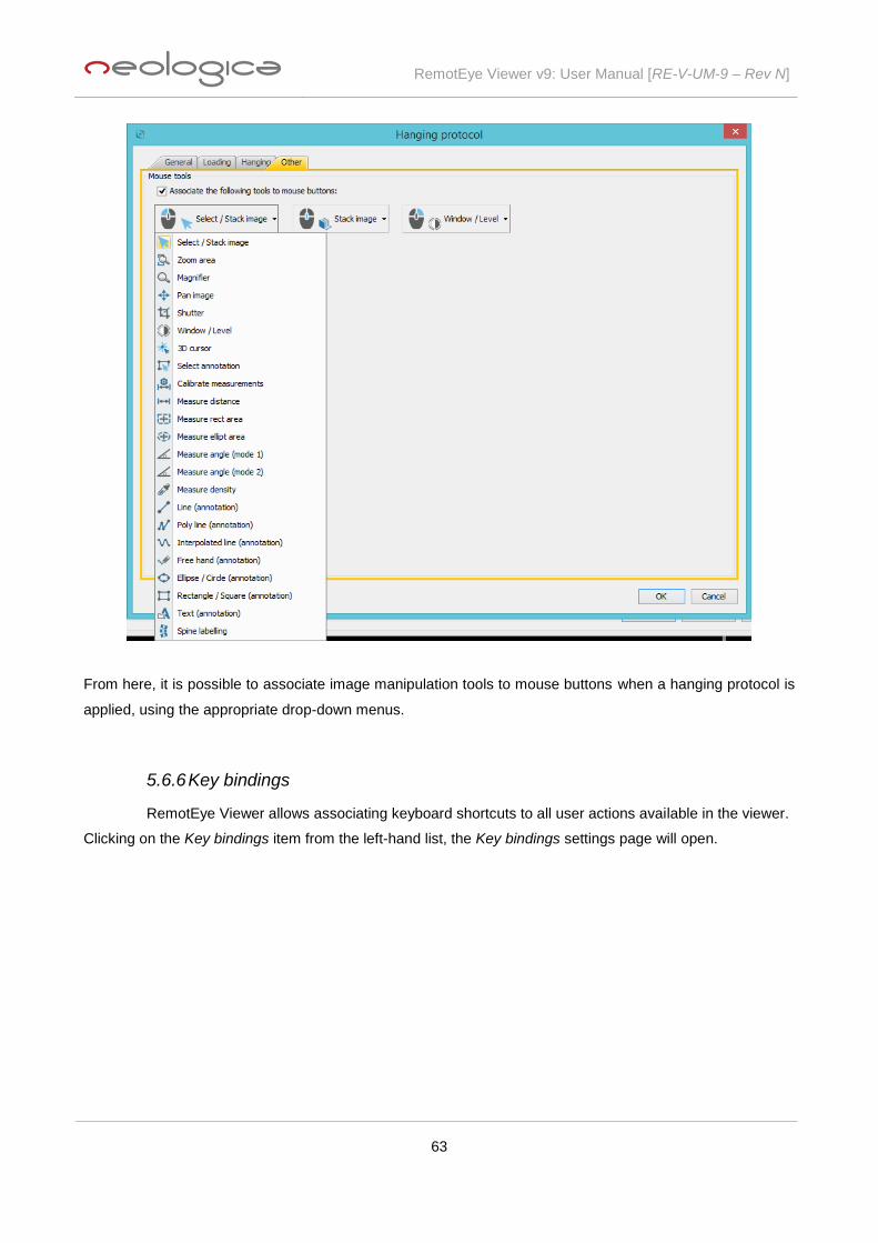
RemotEye Viewer v9: User Manual [RE-V-UM-9 – Rev N]
63
From here, it is possible to associate image manipulation tools to mouse buttons when a hanging protocol is
applied, using the appropriate drop-down menus.
5.6.6 Key bindings
RemotEye Viewer allows associating keyboard shortcuts to all user actions available in the viewer.
Clicking on the Key bindings item from the left-hand list, the Key bindings settings page will open.

RemotEye Viewer v9: User Manual [RE-V-UM-9 – Rev N]
64
As you can see, user can select 3 different tabs related to 3 different kinds of shortcuts: Viewer-level
shortcuts, Screen-level shortcuts, and Study-level shortcuts. These 3 levels correspond with the scope of the
actions which can be associated to shortcuts under each tab.
Clicking on the Add shortcut button, the following dialog box will appear:
From here, user can associate a keyboard shortcut (or binding) to each one of the actions included in the
Action description drop-down menu. The set of available actions varies according to the shortcut level.
Here are some examples of Action description drop-down menus, related respectively to Viewer-level
shortcuts, Screen-level shortcuts, and Study-level shortcuts:

RemotEye Viewer v9: User Manual [RE-V-UM-9 – Rev N]
65
Through the Keyboard shortcut field, it is possible to directly type the combination of keyboard keys (e.g.,
CTRL + other key, CTRL + ALT + other key, SHIFT + CTRL + other key, F keys, etc.) to be associated with
the selected action.
Once an Action / keyboard shortcut association is saved by pressing the OK button, it will appear in the list
related to the specific shortcuts level. Pressing the Clear shortcut button, the typed keys combination will be
cleared.
In addition, from each shortcuts level page, user can view or edit a selected association, pressing the View /
Modify button, as well as remove a specific association or all associations related to that level, clicking
respectively on the Remove or Remove all buttons.

RemotEye Viewer v9: User Manual [RE-V-UM-9 – Rev N]
66
While using keyboard shortcuts (or key bindings) during normal usage of the software, user has to consider
that if input focus is on a specific study, first of all matching of a given key stroke with the study-level key
bindings will be evaluated. In case no match is found, then screen-level key bindings will be evaluated. If no
match is found again, then viewer-level key bindings will be evaluated. On the other side, if input focus is not
on a specific study, but on a generic GUI component residing on a given screen, then screen-level key
bindings will be evaluated. In case no match is found, then viewer-level key bindings will be evaluated.
5.6.7 Local storage preferences
RemotEye Viewer allows configuring some preferences related to local storage of DICOM files.
The Local storage preferences page can be displayed by selecting the Local storage preferences menu item
of the Settings menu.
In particular, RemotEye Viewer supports a “local cache” for DICOM files, where all files downloaded or
prefetched by the viewer are stored. DICOM files stored in this cache are indexed in such a way RemotEye
Viewer will be able to load local files instead of downloading remote files whenever possible, thus greatly
improving the efficiency and speed of the load operation.
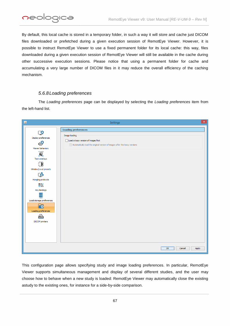
RemotEye Viewer v9: User Manual [RE-V-UM-9 – Rev N]
67
By default, this local cache is stored in a temporary folder, in such a way it will store and cache just DICOM
files downloaded or prefetched during a given execution session of RemotEye Viewer. However, it is
possible to instruct RemotEye Viewer to use a fixed permanent folder for its local cache: this way, files
downloaded during a given execution session of RemotEye Viewer will still be available in the cache during
other successive execution sessions. Please notice that using a permanent folder for cache and
accumulating a very large number of DICOM files in it may reduce the overall efficiency of the caching
mechanism.
5.6.8 Loading preferences
The Loading preferences page can be displayed by selecting the Loading preferences item from
the left-hand list.
This configuration page allows specifying study and image loading preferences. In particular, RemotEye
Viewer supports simultaneous management and display of several different studies, and the user may
choose how to behave when a new study is loaded: RemotEye Viewer may automatically close the existing
astudy to the existing ones, for instance for a side-by-side comparison.

RemotEye Viewer v9: User Manual [RE-V-UM-9 – Rev N]
68
Finally, if the back-end implementation supports this feature, user will be able to choose whether a lossy
version of each study shall be loaded first, each time the loading of a study is requested. This feature allows
to greatly reduce the initial download time of a study, since lossy images are significantly smaller than the
corresponding original images. Once the user will have explored the (lossy) study and will have identified the
most relevant series, it will be able to request the original version of specific series or of the entire study,
through the Load original version button available in the Series toolbar (to download the original version of
the images of a specific series) and in the Study toolbar (to download the original version of all images of the
study).
Important note: it is strongly recommended to always use the original version of the images for
every diagnostic purpose (e.g., diagnostic reporting). RemotEye Viewer will display a warning each
time a critical operation (e.g., diagnostic reporting) will be attempted on a lossy version of the
images.
5.6.9 DICOM printers
In order to be able to send DICOM print commands to one of more DICOM printers, these DICOM
printers must be preventively configured on RemotEye Viewer. This can be done by selecting the DICOM
printers item the left-hand list of the Settings dialog box. The DICOM printers page will appear, as shown in
the following picture:
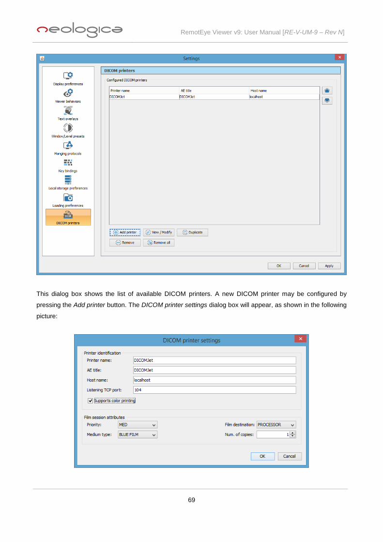
RemotEye Viewer v9: User Manual [RE-V-UM-9 – Rev N]
69
This dialog box shows the list of available DICOM printers. A new DICOM printer may be configured by
pressing the Add printer button. The DICOM printer settings dialog box will appear, as shown in the following
picture:
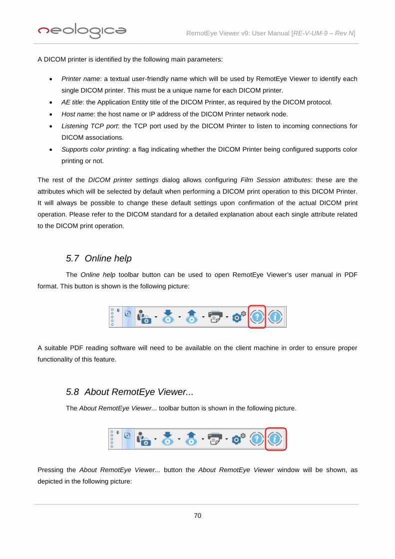
RemotEye Viewer v9: User Manual [RE-V-UM-9 – Rev N]
70
A DICOM printer is identified by the following main parameters:
Printer name: a textual user-friendly name which will be used by RemotEye Viewer to identify each
single DICOM printer. This must be a unique name for each DICOM printer.
AE title: the Application Entity title of the DICOM Printer, as required by the DICOM protocol.
Host name: the host name or IP address of the DICOM Printer network node.
Listening TCP port: the TCP port used by the DICOM Printer to listen to incoming connections for
DICOM associations.
Supports color printing: a flag indicating whether the DICOM Printer being configured supports color
printing or not.
The rest of the DICOM printer settings dialog allows configuring Film Session attributes: these are the
attributes which will be selected by default when performing a DICOM print operation to this DICOM Printer.
It will always be possible to change these default settings upon confirmation of the actual DICOM print
operation. Please refer to the DICOM standard for a detailed explanation about each single attribute related
to the DICOM print operation.
5.7 Online help
The Online help toolbar button can be used to open RemotEye Viewer's user manual in PDF
format. This button is shown is the following picture:
A suitable PDF reading software will need to be available on the client machine in order to ensure proper
functionality of this feature.
5.8 About RemotEye Viewer...
The About RemotEye Viewer... toolbar button is shown in the following picture.
Pressing the About RemotEye Viewer... button the About RemotEye Viewer window will be shown, as
depicted in the following picture:

RemotEye Viewer v9: User Manual [RE-V-UM-9 – Rev N]
71
This window provides general information about the current version of the RemotEye Viewer software
module.
6 Image manipulation toolbar
The Image manipulation toolbar contains buttons representing all operations which can be
performed on medical images, and all settings which can be applied to the display of those images.
When moving the mouse pointer over each single Image manipulation toolbar's button, a tooltip text will
appear, providing additional information about the function of the underlying button.
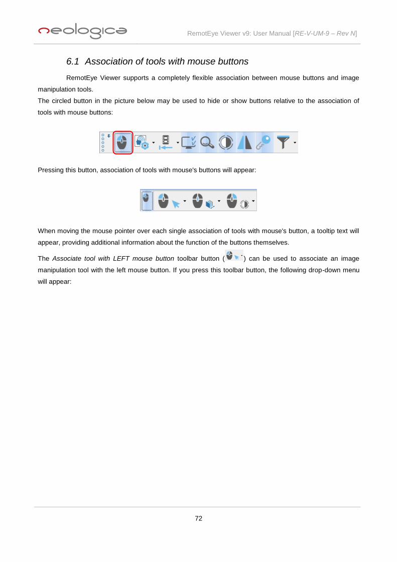
RemotEye Viewer v9: User Manual [RE-V-UM-9 – Rev N]
72
6.1 Association of tools with mouse buttons
RemotEye Viewer supports a completely flexible association between mouse buttons and image
manipulation tools.
The circled button in the picture below may be used to hide or show buttons relative to the association of
tools with mouse buttons:
Pressing this button, association of tools with mouse's buttons will appear:
When moving the mouse pointer over each single association of tools with mouse's button, a tooltip text will
appear, providing additional information about the function of the buttons themselves.
The Associate tool with LEFT mouse button toolbar button ( ) can be used to associate an image
manipulation tool with the left mouse button. If you press this toolbar button, the following drop-down menu
will appear:

RemotEye Viewer v9: User Manual [RE-V-UM-9 – Rev N]
73
The Associate tool with RIGHT mouse button toolbar button ( ) can be used to associate an image
manipulation tool with the right mouse button. If you press this toolbar button, the same drop-down menu as
above will appear.
Each available image manipulation tool can be independently associated with the left mouse button and with
the right mouse button. All combinations of left / right mouse button tools are supported.
The Associate tool with mouse WHEEL toolbar button ( ) can be used to associate Stack image or
Zoom image tools with the mouse wheel. If you press this toolbar button, the following drop-down menu will
appear:

RemotEye Viewer v9: User Manual [RE-V-UM-9 – Rev N]
74
This flexible functionality implies that each single image tool is always usable with a single mouse button. For
instance, the Poly line (annotation) tool allows drawing a poly-line with a single mouse button; double-click of
the associated mouse button must be used to conclude the shape.
The icon of the tool currently associated with the left and right mouse buttons will appear in the Image
manipulation toolbar, next to the left, right and wheel mouse button icons.
Each image manipulation tool has its own associated Tool options panel. When the user starts using an
image manipulation tool on a medical image, the Tool options panel related to that tool will be displayed and
become active. The following paragraphs will describe each image manipulation tool, as well as the options
and information available in the Tool options panel associated with each tool.
6.1.1 Select/Stack image
The Select/Stack image tool allows selecting an image panel on a screen, by a single click on the
image. To unselect the image you have to click on the image while holding the Ctrl key pressed. Also, it is
possible to scroll through the images of the series by dragging with the associated mouse button over the
image (“stack” operation). It is additionally possible to exploit a ‘Scroll to frame #’ screen action, which can be
associated with a keyboard shortcut.
The Tool options panel associated with this tool, shown in the picture below, displays basic information about
the currently selected image.
6.1.2 Zoom area
The Zoom area tool allows zooming a specific rectangular portion of the currently selected image.
The rectangular region to be zoomed can be selected by dragging with the associated mouse button over
the medical image. If the SHIFT key of the keyboard is kept pressed, then the zoom area will be forced to a
square shape.
The Tool options panel associated with this tool is shown in the picture below:

RemotEye Viewer v9: User Manual [RE-V-UM-9 – Rev N]
75
The interpolation algorithm used to zoom images can be chosen by dragging the Interpolation quality slider
on the Tool options panel associated with this tool. Three different interpolation types are supported,
providing a speed vs quality trade-off.
6.1.3 Magnifier
The Magnifier tool allows magnifying a moving portion of the image, by dragging with the
associated mouse button over the image.
The Tool options panel associated with this tool is shown in the picture below:
The magnification factor used by the magnifier, as well as the size of the magnifier itself, can be modified by
dragging the Zoom factor and the Magnifier size sliders on the Tool options panel associated with this tool.
6.1.4 Pan image
The Pan image tool allows panning over the currently selected image, by dragging with the
associated mouse button over the image.
The Tool options panel associated with this tool is shown in the picture below:

RemotEye Viewer v9: User Manual [RE-V-UM-9 – Rev N]
76
6.1.5 Shutter
The Shutter tool allows applying a shutter over the image, i.e., hiding a sub-region of the image,
which is not interesting for medical purposes. The shutter is always applied to the entire series.
The Tool options panel associated with this tool is shown in the picture below:
You can select the shape of the shutter to apply on the series by selecting the appropriate Shape option in
this panel. In order to draw a Rectangular or Circular shutter, it is sufficient to select the Shutter tool, to drag
with the associated mouse button over the image, and then to release the mouse button when you are
satisfied with the size of the shutter. On the other side, if you want to draw a Polygonal shutter, then you
need to click the associated mouse button on every point of the polygon contour that you want to define.
When you want to define the last point of the contour, double-click the associated mouse button, and the
polygonal shutter will be complete.
6.1.6 Window / Level
The Window / Level tool allows modifying the window width and window level values (also known
as "window center") for the gray levels (or colors) of the current image. The Window / Level values are given
in Hounsfield Units if the selected image panel contains a CT image.
You may change the Window,Level values by dragging with the associated mouse button over the image.
The Tool options panel associated with this tool is shown in the picture below:
If the Apply to series toggle button is pressed (i.e., selected) then the Window / Level changes will be applied
to the entire series.
It is also possible to change the sensitivity of mouse dragging movements for contrast changes, by dragging
the Sensitity slider in this panel.

RemotEye Viewer v9: User Manual [RE-V-UM-9 – Rev N]
77
Window width and window level values can also be changed by dragging the mouse pointer on the Window /
Level widget (the square with a black background). Right-clicking on the Window / Level widget causes
restoring the window/level values contained in the DICOM file (if they are present). You may also change the
window/level values by selecting one of the available contrast presets (from the Presets drop-down list).
Finally, you can manually enter window/level values in the W / W and W / L text fields, and press Enter on
your keyboard to confirm and apply them.
Press the Auto button in order to apply an automatic “optimal” windowing for the currently selected image.
The Reset button may be used to restore the original Window / Level setting suggested in the DICOM data
set (if present).
6.1.7 3D cursor
The 3D cursor tool (also known as "3D localizer" tool) allows a fast navigation through CT or MR
series, and is able to show the location of the point indicated by the mouse cursor (over the current image)
also on the other displayed series or, when the MPR view is active, on the different cut planes of the MPR. In
particular, when the mouse button associated with this tool is pressed or dragged on a particular point of the
current image (the "3D point", from now on), the other series are scrolled up to the image containing that
same point in the 3D patient coordinates space, and the location of the "3D point" is shown on those images.
The Tool options panel associated with this tool is shown in the picture below:
6.1.8 Select annotation
The Select annotation tool allows selecting a measurement or graphical annotation which already
exists on the current medical image. Selection of the annotation shape is done by clicking with the
associated mouse button over the annotation shape itself. Once the annotation is selected, it is possible to
move and modify the shape itself, by dragging with the associated mouse button over specific points of the
selected annotation shape. If dragging is started over one of the displayed selection handles (the small red
squares), then the shape will be modified, by moving the relevant selection handle point. On the other side, if
dragging is started over a generic point of the shape (i.e., not over a selection handle), then the entire
annotation is moved, with no modifications to its geometric shape.
The generic Tool options panel associated with this tool is shown in the picture below:

RemotEye Viewer v9: User Manual [RE-V-UM-9 – Rev N]
78
Once a measurement or graphical annotation shape is selected, the Tool options panel will reflect the
properties of the specific selected shape, and will offer more options. Also, when an annotation is selected,
you can delete it by pressing the Delete key on the keyboard, or the Delete button in the Tool options panel.
Finally, once an annotation is selected, you can select the previous or next annotation of the current image
by pressing the ‘-’ or ‘+’ keys on the numeric keypad of your keyboard.
6.1.9 Measurement tools
RemotEye Viewer supports several measurements tools, described in the following sub-
paragraphs.
Warning: measurements taken through the RemotEye Viewer software are based on pixel-to-
millimetres calibration information which is read from the DICOM dataset. This calibration information
is stored by the modality which originally acquired the medical images. RemotEye Viewer has no
mean to guarantee that the calibration information is correct and accurate, hence it has no mean to
guarantee that the final measurements taken by the software are actually accurate. It is
recommended that the user of RemotEye Viewer critically checks the result of each measurement.
6.1.9.1 Calibrate measurements
The Calibrate measurements tool allows calibrating distances, that is, assigning an actual known
distance value (in mm, cm or inches) to a given distance measured on-screen, over the image. In order to
perform calibration, select the Calibrate measurements tool and drag with the associated mouse button over
the image, on the distance that you want to calibrate / set. As soon as the drag operation has finished, the
Calibrate measurements dialog will appear:

RemotEye Viewer v9: User Manual [RE-V-UM-9 – Rev N]
79
User needs to enter the Actual distance corresponding to the measured Pixel distance. User also has the
option of specifying that the following calibration must be applied to the whole series, that is, to all images
belonging to the current series. If this option is not checked, then the calibration will only be applied to the
DICOM file containing the current image.
The Tool options panel associated with this tool is shown in the picture below:
This panel basically allows you to modify the measurement unit used for calibration.
6.1.9.2 Measure distance
The Measure distance tool allows measuring linear distances on the selected medical image. The
measurement is performed by dragging with the associated mouse button over the image, and releasing the
mouse button once you traced the distance that you want to measure.
The Tool options panel associated with this tool is shown in the picture below:
The user may choose to create an annotation of each measurement, thus leaving a persistent graphic object
over the image, by enabling the Create annotation checkbox. In addition, the user may choose to add the

RemotEye Viewer v9: User Manual [RE-V-UM-9 – Rev N]
80
drawn measurement annotations to all images of the current series, by pressing the Apply to series toggle
button. If the Create annotation option is disabled, the graphic object representing the current measurement
over the image will immediately disappear when the measurement is complete (i.e., the mouse button is
released).
The user may also choose whether to display an on-screen label of each performed measurement, by
checking or unchecking the Show on-screen meas. option.
The measurement unit used for measurements may be chosen by selecting the corresponding option (mm,
cm, or in) in this Tool options panel.
Finally, it is possible to delete the currently selected annotation by pressing the Delete button, or to delete all
measurement annotations by pressing the Delete all meas.
6.1.9.3 Measure horiz/vert distance
The Measure horiz / vert distance tool allows measuring linear horizontal or vertical distances on
the selected medical image. The measurement is performed by dragging with the associated mouse button
over the image, starting the dragging operation on the start point and releasing the mouse button on the end
point of the vertical or horizontal distance that you want to measure.
The Tool options panel associated with this tool is shown in the picture below:
The user may choose whether he wants to compute the horizontal offset (i.e., horizontal distance) or the
vertical offset (i.e., vertical distance) between the start and end point which have been identified through the
mouse drag operation, by acting on the Type drop-down box.
Computation of the Cardio-Thoracic Ratio (CTR)
The Measure horiz / vert distance tool allows computing the value of the Cardio-Thoracic Ratio. Once the
appropriate chest xray image is selected, just select Horizontal offset in the Type drop-down of the Tool
options panel. Take a first horizontal distance measurement corresponding with the cardiac size, then a
second horizontal distance measurement corresponding with the maximum width of the thoracic cavity.
Finally, press the Measure CTR button, and you will get the value of CTR. According to literature, a value of
CTR above 50% is considered abnormal.
Warning: in order to guarantee maximum accuracy, it is recommended that the Measure CTR tool is

RemotEye Viewer v9: User Manual [RE-V-UM-9 – Rev N]
81
only used on a PA (Posterior - Anterior) chest xray image.
6.1.9.4 Measure distances and angles
The Measure distances and angles tool allows measuring angles among an arbitrary number of
segments, which may be intersecting or not. Also, the distances represented by each segment are computed
and displayed. The measurement is performed by dragging with the associated mouse button over the
image, in order to trace each segment. A double-click with the associated mouse button will terminate the
sequence of segments. Once the sequence is terminated, all distances and angles will be computed and
shown.
The Tool options panel associated with this tool is shown in the picture below:
The user may choose whether he wants only angles among intersecting segments are computed and shown,
by checking the Show inters. angles only option. Also, it is possible to set the number of segments in a
sequence to a fixed value, by acting on the Num of segments drop-down box: this will eliminate the need for
a double-click to terminate the sequence, as the sequence will be automatically terminated once the just-set
number of segments will be traced.
Each sequence of segments is independent from other sequences, even on a single image. Once a
sequence is terminated, it can still be modified both in terms of position of each single segment and in terms
of number of segments: this last aspect can be managed by acting on the Add segment(s) and Remove last
segment buttons (a sequence must be selected first).
6.1.9.5 Measure rect area
The Measure rect area tool allows measuring rectangular areas on the selected medical image.
Information about the surface, the perimeter, the minimum/maximum/mean density, and the standard
deviation of the densities within the rectangular area is provided. The measurement is performed by
dragging with the associated mouse button over the image, and releasing the mouse button once you traced
the rectangular area that you want to measure. Keeping the Shift key of the keyboard pressed will force the
area to be exactly square.
The Tool options panel associated with this tool is shown in the picture below:

RemotEye Viewer v9: User Manual [RE-V-UM-9 – Rev N]
82
Please refer to the paragraph about the Measure distance tool for an explanation of the options available in
this panel.
In addition, as shown in the following screenshots, on PET images containing the appropriate data elements
in their DICOM dataset, RemotEye Viewer is able to provide the minimum/maximum/mean SUV, and the
standard deviation of the SUV within the selected rectangular area.
SUV (Standardized Uptake Values) is commonly used in PET image analysis. It measures the concentration
of a radiotracer in a defined region of interest (ROI), which provides interesting diagnostic information. In
particular, RemotEye Viewer computes SUV according to the "SUV Body Weight" algorithm which is based
on the following formula:
suvValue[body weight] = (activityConcentration / (radionuclTotalDoseBq *
decayFactor)) * patientWeightG
where:
activityConcentration: the pixel value in the image, after processing of Modality LUT.
radionuclTotalDoseBq: the radionuclide total dose, expressed in Bequerels.
decayFactor: the decay factor.
patientWeightG: the patient's weight, expressed in grams.
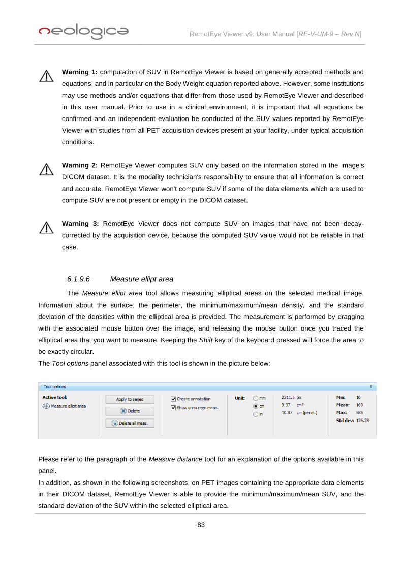
RemotEye Viewer v9: User Manual [RE-V-UM-9 – Rev N]
83
Warning 1: computation of SUV in RemotEye Viewer is based on generally accepted methods and
equations, and in particular on the Body Weight equation reported above. However, some institutions
may use methods and/or equations that differ from those used by RemotEye Viewer and described
in this user manual. Prior to use in a clinical environment, it is important that all equations be
confirmed and an independent evaluation be conducted of the SUV values reported by RemotEye
Viewer with studies from all PET acquisition devices present at your facility, under typical acquisition
conditions.
Warning 2: RemotEye Viewer computes SUV only based on the information stored in the image's
DICOM dataset. It is the modality technician's responsibility to ensure that all information is correct
and accurate. RemotEye Viewer won't compute SUV if some of the data elements which are used to
compute SUV are not present or empty in the DICOM dataset.
Warning 3: RemotEye Viewer does not compute SUV on images that have not been decay-
corrected by the acquisition device, because the computed SUV value would not be reliable in that
case.
6.1.9.6 Measure ellipt area
The Measure ellipt area tool allows measuring elliptical areas on the selected medical image.
Information about the surface, the perimeter, the minimum/maximum/mean density, and the standard
deviation of the densities within the elliptical area is provided. The measurement is performed by dragging
with the associated mouse button over the image, and releasing the mouse button once you traced the
elliptical area that you want to measure. Keeping the Shift key of the keyboard pressed will force the area to
be exactly circular.
The Tool options panel associated with this tool is shown in the picture below:
Please refer to the paragraph of the Measure distance tool for an explanation of the options available in this
panel.
In addition, as shown in the following screenshots, on PET images containing the appropriate data elements
in their DICOM dataset, RemotEye Viewer is able to provide the minimum/maximum/mean SUV, and the
standard deviation of the SUV within the selected elliptical area.

RemotEye Viewer v9: User Manual [RE-V-UM-9 – Rev N]
84
Please refer to the previous paragraph "Measure rect area" for details and recommendations about SUV
(Standardized Uptake Values).
6.1.9.7 Measure angle (mode 1)
The Measure angle (mode 1) tool allows measuring angles on the selected medical image. The
measurement is performed by clicking three times with the associated mouse button over the image; each
click identifies one of the three points defining the angle to be measured.
The Tool options panel associated with this tool is shown in the picture below:
Please refer to the paragraph of the Measure distance tool for an explanation of the options available in this
panel.
6.1.9.8 Measure angle (mode 2)
The Measure angle (mode 2) tool allows measuring angles on the selected medical image. The
measurement is performed by drawing two segments over the image; each segment can be drawn by
dragging with the associated mouse button over the image, and releasing it when each segment has the
desired properties.
The Tool options panel associated with this tool is shown in the picture below:

RemotEye Viewer v9: User Manual [RE-V-UM-9 – Rev N]
85
Please refer to the paragraph of the Measure distance tool for an explanation of the options available in this
panel.
6.1.9.9 Measure density
The Measure density tool allows measuring densities on the selected medical image.
The measurement is performed by dragging with the associated mouse button over the image. Once the
mouse button is released, the density measurement is eliminated.
The Tool options panel associated with this tool is shown in the picture below:
Moreover, on PET images containing the appropriate data elements in their DICOM dataset, RemotEye
Viewer is able to provide the SUV for each point which is selected on the image. The value provided in
square brackets is the actual detected pixel value, after modality LUT transformation.
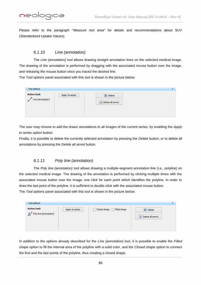
RemotEye Viewer v9: User Manual [RE-V-UM-9 – Rev N]
86
Please refer to the paragraph "Measure rect area" for details and recommendations about SUV
(Standardized Uptake Values).
6.1.10 Line (annotation)
The Line (annotation) tool allows drawing straight annotation lines on the selected medical image.
The drawing of the annotation is performed by dragging with the associated mouse button over the image,
and releasing the mouse button once you traced the desired line.
The Tool options panel associated with this tool is shown in the picture below:
The user may choose to add the drawn annotations to all images of the current series, by enabling the Apply
to series option button.
Finally, it is possible to delete the currently selected annotation by pressing the Delete button, or to delete all
annotations by pressing the Delete all annot button.
6.1.11 Poly line (annotation)
The Poly line (annotation) tool allows drawing a multiple-segment annotation line (i.e., polyline) on
the selected medical image. The drawing of the annotation is performed by clicking multiple times with the
associated mouse button over the image, one click for each point which identifies the polyline. In order to
draw the last point of the polyline, it is sufficient to double-click with the associated mouse button.
The Tool options panel associated with this tool is shown in the picture below:
In addition to the options already described for the Line (annotation) tool, it is possible to enable the Filled
shape option to fill the internal area of the polyline with a solid color, and the Closed shape option to connect
the first and the last points of the polyline, thus creating a closed shape.

RemotEye Viewer v9: User Manual [RE-V-UM-9 – Rev N]
87
6.1.12 Interpolated line (annotation)
The Interpolated line (annotation) tool allows drawing an interpolated annotation line on the
selected medical image. The drawing of the annotation is performed by clicking multiple times with the
associated mouse button over the image, one click for each point which identifies the interpolated line. In
order to draw the last point of the interpolated line, it is sufficient to double-click with the associated mouse
button.
The Tool options panel associated with this tool is shown in the picture below:
Please refer to the paragraph of the Poly line (annotation) tool for an explanation of the options available in
this panel.
6.1.13 Free hand (annotation)
The Free hand (annotation) tool allows drawing a free-hand annotation line on the selected medical
image. The drawing of the annotation is performed by dragging with the associated mouse button over the
image, and releasing it once the drawing of the free-hand line is finished.
The Tool options panel associated with this tool is shown in the picture below:
Please refer to the paragraph of the Poly line (annotation) tool for an explanation of the options available in
this panel.

RemotEye Viewer v9: User Manual [RE-V-UM-9 – Rev N]
88
6.1.14 Ellipse / Circle (annotation)
The Ellipse / Circle (annotation) tool allows drawing an elliptical annotation shape on the selected
medical image. The drawing is performed by dragging with the associated mouse button over the image, and
releasing the mouse button once you traced the desired elliptical shape. Keeping the Shift key of the
keyboard pressed will force the shape to be exactly circular.
The Tool options panel associated with this tool is shown in the picture below:
In addition to the options already described for the Line (annotation) tool, it is possible to enable the Filled
shape option to fill the internal area of the ellipse with a solid color.
6.1.15 Rectangle / Square (annotation)
The Rectangle / Square (annotation) tool allows drawing a rectangular annotation shape on the
selected medical image. The drawing is performed by dragging with the associated mouse button over the
image, and releasing the mouse button once you traced the desired rectangular shape. Keeping the Shift
key of the keyboard pressed will force the shape to be exactly square.
The Tool options panel associated with this tool is shown in the picture below:
In addition to the options already described for the Line (annotation) tool, it is possible to enable the Filled
shape option to fill the internal area of the rectangle with a solid color.
6.1.16 Text (annotation)
The Text (annotation) tool allows drawing a textual annotation on the selected medical image. In
order to enter the textual annotation, it is necessary to click with the associated mouse button over the image,

RemotEye Viewer v9: User Manual [RE-V-UM-9 – Rev N]
89
in the exact point where the text annotation must be applied. The Text annotation dialog box will immediately
appear:
Please enter the text of your annotation, then press the OK button or press Enter on your keyboard. The
Text annotation dialog box will disappear, and the text annotation will start floating on the image as you
move your mouse pointer: click again with the associated mouse button in order to fix the position of the
label.
The Tool options panel associated with this tool is shown in the picture below:
In addition to the options already described for the Line (annotation) tool, it is possible to enable the Show
anchor point option to show the point of application of the textual annotation. If this option is disabled, the
textual annotation will still be visible, but the exact application point will not be explicitly shown.
6.1.17 Spine labelling
The Spine labelling tool is intended to allow labelling of vertebrae on MR or CT spine studies.
Spine labels placed by user on a CT or MR slice become 3D points in the patient's coordinates space, and
are displayed in all different views / series within the study (sagittal, axial, coronal and even arbitrary views
generated through MPR).
In order to properly use this tool, user shall follow these steps:
1) Open a CT or MR study where the patient's spine has been imaged. In particular, user has to make
sure a sagittal series is available in the study and visible in the viewer. If no sagittal series is present
in the study, user may use RemotEye Viewer's Multi-Planar Reconstruction (MPR) feature to
artificially generate the sagittal view.
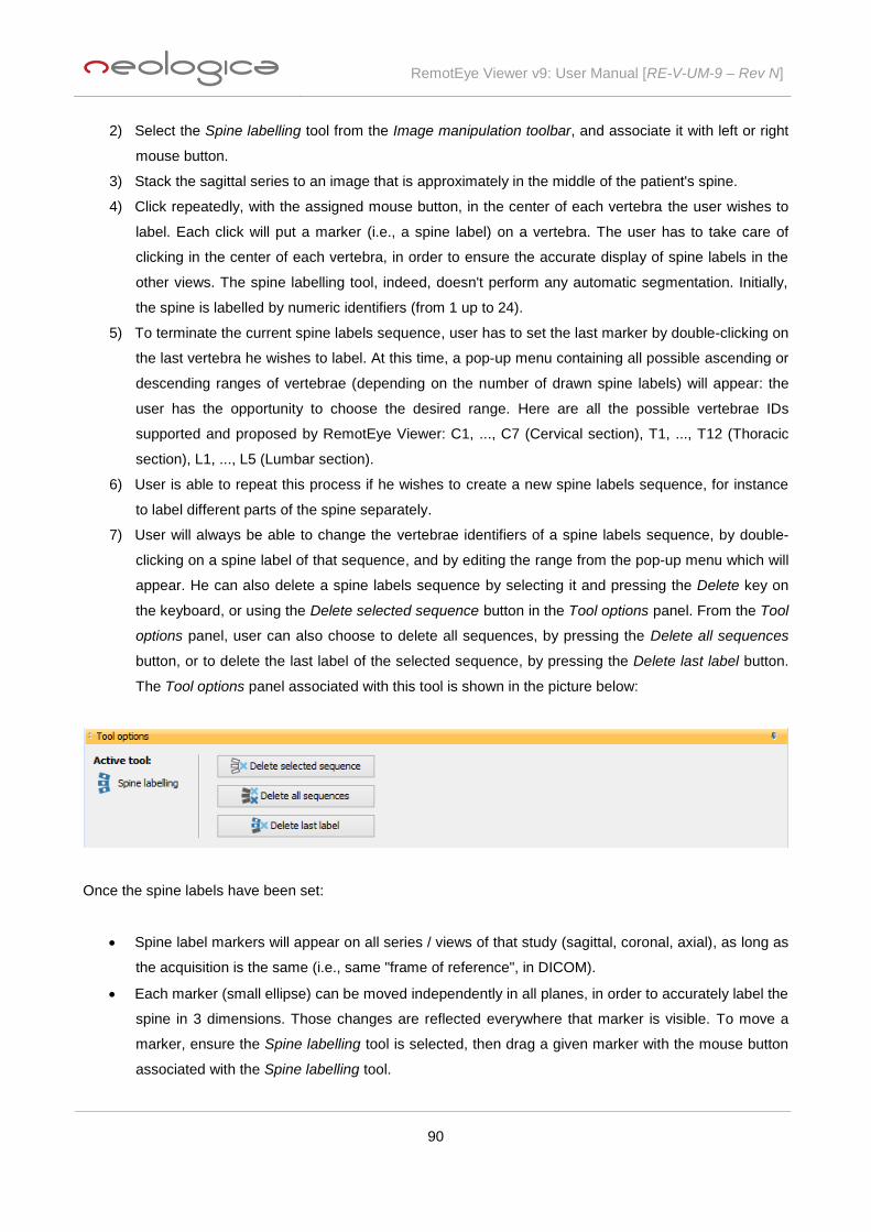
RemotEye Viewer v9: User Manual [RE-V-UM-9 – Rev N]
90
2) Select the Spine labelling tool from the Image manipulation toolbar, and associate it with left or right
mouse button.
3) Stack the sagittal series to an image that is approximately in the middle of the patient's spine.
4) Click repeatedly, with the assigned mouse button, in the center of each vertebra the user wishes to
label. Each click will put a marker (i.e., a spine label) on a vertebra. The user has to take care of
clicking in the center of each vertebra, in order to ensure the accurate display of spine labels in the
other views. The spine labelling tool, indeed, doesn't perform any automatic segmentation. Initially,
the spine is labelled by numeric identifiers (from 1 up to 24).
5) To terminate the current spine labels sequence, user has to set the last marker by double-clicking on
the last vertebra he wishes to label. At this time, a pop-up menu containing all possible ascending or
descending ranges of vertebrae (depending on the number of drawn spine labels) will appear: the
user has the opportunity to choose the desired range. Here are all the possible vertebrae IDs
supported and proposed by RemotEye Viewer: C1, ..., C7 (Cervical section), T1, ..., T12 (Thoracic
section), L1, ..., L5 (Lumbar section).
6) User is able to repeat this process if he wishes to create a new spine labels sequence, for instance
to label different parts of the spine separately.
7) User will always be able to change the vertebrae identifiers of a spine labels sequence, by double-
clicking on a spine label of that sequence, and by editing the range from the pop-up menu which will
appear. He can also delete a spine labels sequence by selecting it and pressing the Delete key on
the keyboard, or using the Delete selected sequence button in the Tool options panel. From the Tool
options panel, user can also choose to delete all sequences, by pressing the Delete all sequences
button, or to delete the last label of the selected sequence, by pressing the Delete last label button.
The Tool options panel associated with this tool is shown in the picture below:
Once the spine labels have been set:
Spine label markers will appear on all series / views of that study (sagittal, coronal, axial), as long as
the acquisition is the same (i.e., same "frame of reference", in DICOM).
Each marker (small ellipse) can be moved independently in all planes, in order to accurately label the
spine in 3 dimensions. Those changes are reflected everywhere that marker is visible. To move a
marker, ensure the Spine labelling tool is selected, then drag a given marker with the mouse button
associated with the Spine labelling tool.

RemotEye Viewer v9: User Manual [RE-V-UM-9 – Rev N]
91
Only markers that are within 2.5 cm from the current image plane (in the patient space) will be shown.
So, user will notice that some (or all) markers will disappear as he navigates through images in a
given series.
Frequently, in the "non-upright" views (e.g., axial views), markers would be overlapping. In these
cases, a single marker will be shown by the viewer, but the related text label will show the identifiers
of both markers (e.g., C4/C5); the first identifier will indicate the marker that is closest. If user will
move such a marker on that view, it will be the closest marker (C4) that he will see moving in the
other images. However, if one of the markers is very close to the current image plane (< 2 mm), the
text label will only show its identifier, even though there is a second marker within 2.5 cm.
On the other side, in "upright" views (e.g., sagittal views) all markers will always be shown separately,
even when they are very close.
6.1.18 Stack image
If the Stack Image tool is associated with the mouse wheel, scrolling the mouse wheel will cause
scrolling the images of the current series (equivalent to Previous frame and Next frame buttons optionally
available in the Series toolbar, depending on the viewer configuration). If the Alt key on the keyboard is kept
pressed while scrolling the mouse wheel, a scrolling of the current scene (i.e., page of images) will happen
(equivalent to Previous scene and Next scene buttons optionally available in the Series toolbar, depending
on the viewer configuration).
6.1.19 Zoom image
If the Zoom Image tool is associated with the mouse wheel, scrolling the mouse wheel will cause a
zoom in or zoom out operation (depending on the direction of wheel rotation) on the current image.

RemotEye Viewer v9: User Manual [RE-V-UM-9 – Rev N]
92
6.2 Image operations options
The Image operations options button of the Image manipulation toolbar allows user to perform the
following operations, shown in the drop down menu:
Zoom operations can be applied to a single image panel, to a series panel or to the study panel; whereas
contrast, geometric and enhancement operations can be applied to a single image, to a series or to the
entire study, depending on the user's preference.
6.3 Reset operations
The Image manipulation toolbar contains some buttons which allow resetting all changes done on
the current image, on all images of the current series, or on all images of the current study. The "reset"
toolbar button, may correspond with the Reset selected image, or with the Reset selected series, or with the
Reset selected study action, depending on which item is selected in the related drop-down menu, which can
be shown by pressing the down arrow next to the "reset" toolbar button:
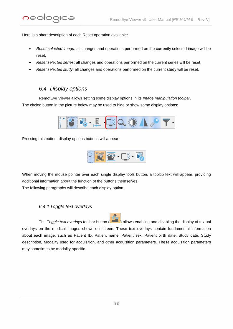
RemotEye Viewer v9: User Manual [RE-V-UM-9 – Rev N]
93
Here is a short description of each Reset operation available:
Reset selected image: all changes and operations performed on the currently selected image will be
reset.
Reset selected series: all changes and operations performed on the current series will be reset.
Reset selected study: all changes and operations performed on the current study will be reset.
6.4 Display options
RemotEye Viewer allows setting some display options in its Image manipulation toolbar.
The circled button in the picture below may be used to hide or show some display options:
Pressing this button, display options buttons will appear:
When moving the mouse pointer over each single display tools button, a tooltip text will appear, providing
additional information about the function of the buttons themselves.
The following paragraphs will describe each display option.
6.4.1 Toggle text overlays
The Toggle text overlays toolbar button ( ) allows enabling and disabling the display of textual
overlays on the medical images shown on screen. These text overlays contain fundamental information
about each image, such as Patient ID, Patient name, Patient sex, Patient birth date, Study date, Study
description, Modality used for acquisition, and other acquisition parameters. These acquisition parameters
may sometimes be modality-specific.

RemotEye Viewer v9: User Manual [RE-V-UM-9 – Rev N]
94
6.4.2 Display reference lines
The Display reference lines toolbar button ( ) allows setting preferences about the display of
reference lines (also known as “scout lines”) on CT or MR images. This toolbar button is only enabled with
CT or MR images. If you press it, the following drop-down menu will appear:
The Display current reference line menu item allows enabling and disabling the display of reference lines
related to the currently selected image on all other displayed and intersecting series. A reference line
indicates the location of an image slice (the currently selected image) on another image of an intersecting
plane.
The Display first/last reference lines menu item allows enabling and disabling the display of reference lines
related to the first and last image of the currently selected series.
The Display all reference. lines menu item allows enabling and disabling the display of reference lines
related to all images of the currently selected series.
The following picture shows an example of how reference lines look like on a MR study:
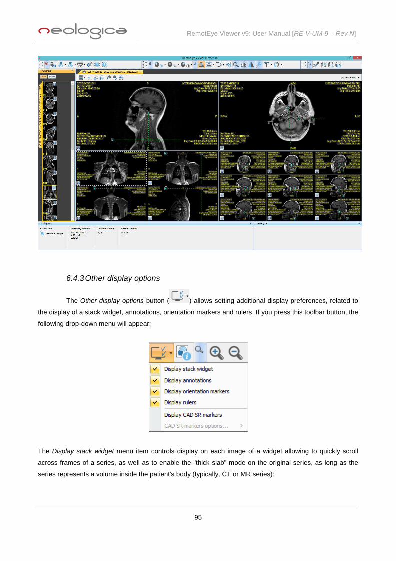
RemotEye Viewer v9: User Manual [RE-V-UM-9 – Rev N]
95
6.4.3 Other display options
The Other display options button ( ) allows setting additional display preferences, related to
the display of a stack widget, annotations, orientation markers and rulers. If you press this toolbar button, the
following drop-down menu will appear:
The Display stack widget menu item controls display on each image of a widget allowing to quickly scroll
across frames of a series, as well as to enable the "thick slab" mode on the original series, as long as the
series represents a volume inside the patient's body (typically, CT or MR series):

RemotEye Viewer v9: User Manual [RE-V-UM-9 – Rev N]
96
When the "thick slab" mode is disabled, the user will be allowed to scroll the series by dragging the white
cursor labelled with the image number. Moreover, a double click on the cursor will allow the user to manually
set the frame he wants to display:
The "thick slab" mode can be enabled by vertically dragging the horizontal line located next to the white
cursor:
The thickness of the "thick slab" will vary depending on the dragging operation.

RemotEye Viewer v9: User Manual [RE-V-UM-9 – Rev N]
97
When the "thick slab" mode is enabled, users will be allowed to change the projection algorithm for the slab
by clicking on the box located underneath the widget (MIP, AvgIP or MinIP algorithms are available). Thick
slab mode can be turned off by double-clicking on the central reference line. Finally, a double click on the
horizontal lines which mark the end of the extent of the thick slab on the widget will allow user to manually
set the slab thickness parameters:
The Display annotations menu item allows enabling and disabling the display of measurement and graphical
annotations over all the displayed images.
The Display orientation markers menu item allows enabling and disabling the display of orientation markers,
normally available on CT and MR images, and sometimes on other kinds of images. If the image orientation
information is present inside the related DICOM image file, the orientation markers will be displayed at the
four edges of each DICOM image. The orientation will be indicated as:
A: Anterior
P: Posterior
I: Inferior
S: Superior
L: Left
R: Right
The Display rulers menu item allows enabling and disabling the display of on-screen rulers showing actual
distances over the displayed images. The rulers show a short tick every 1 cm on the image, and a longer tick
every 5 cm on the image. Rulers will only be displayed on images having the appropriate calibration
information inside the related DICOM image file.
Finally, The Display CAD SR markers functionality will be described in the following paragraph.
6.4.3.1 Mammo CAD markers
RemotEye Viewer supports decoding and display of CAD findings and markers starting from
DICOM Mammo CAD SR files. These files are normally produced by mammography CAD software, and
contain encoded information about the detections the CAD software has done on the images of a specific
mammographic study.

RemotEye Viewer v9: User Manual [RE-V-UM-9 – Rev N]
98
The display of Mammo CAD markers can be enabled and disabled through the Display CAD SR markers
menu item, available in the Other display options drop down menu, described in the previous paragraph.
Moreover, once the Display CAD SR markers item is checked, the CAD SR markers options... item becomes
active as well, as shown in the following image:
From here, it is possible to choose whether to display CAD markers icons only, or CAD marker contours only,
or both. In addition, selecting the appropriate checkbox, RemotEye Viewer will show also a legend related to
the detected CAD findings.
Here is a screenshot showing two images of a mammographic study on which CAD markers and CAD
findings legend are displayed:

RemotEye Viewer v9: User Manual [RE-V-UM-9 – Rev N]
99
RemotEye Viewer is able to show three different types of findings / features:
Mammography breast density: associated with the icon,
Calcification cluster: associated with the icon,
Mass with calcifications: associated with the icon.
While icons are located in the centre of each finding / feature, a contour defines the entire breast area
interested by the finding / feature in question. This contour is the same colour as the related icon.
As mentioned above, enabling the Display CAD findings legend option from the appropriate menu, a legend
showing a summary of the detected findings, will be displayed on the related image.
Finally, moving the mouse over a CAD finding icon or within its contour, a panel providing all the available
information about the finding(s) / feature(s) will appear, as shown in the following image:

RemotEye Viewer v9: User Manual [RE-V-UM-9 – Rev N]
100
Important note: Display of mammo CAD SR markers is disabled upon first display of a loaded
study, in such a way not to influence the radiologist's opinion and diagnosis. For safety and
diagnostic accuracy purposes, indeed, it is important that the radiologist builds its own diagnostic
opinion before seeing the mammo CAD SR markers, which shall only act as an aid and diagnostic
support mean.
6.4.4 Show image information
The Show image information button ( ) of the Image manipulation toolbar allows viewing
information about the currently selected image. If you press this toolbar button, the Current Image Info dialog
box will appear:
This dialog box is composed of several tabs:
Meta-Info tab
Patient tab
Study tab
Series tab
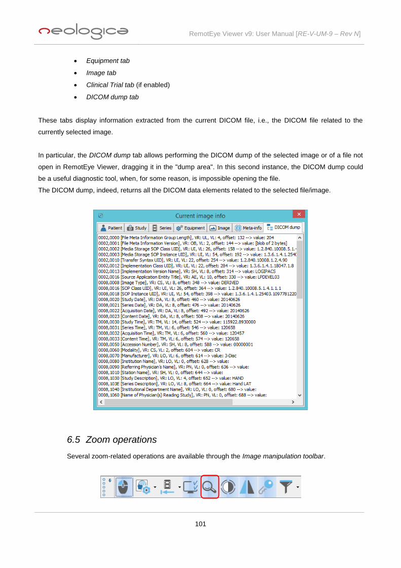
RemotEye Viewer v9: User Manual [RE-V-UM-9 – Rev N]
101
Equipment tab
Image tab
Clinical Trial tab (if enabled)
DICOM dump tab
These tabs display information extracted from the current DICOM file, i.e., the DICOM file related to the
currently selected image.
In particular, the DICOM dump tab allows performing the DICOM dump of the selected image or of a file not
open in RemotEye Viewer, dragging it in the "dump area". In this second instance, the DICOM dump could
be a useful diagnostic tool, when, for some reason, is impossible opening the file.
The DICOM dump, indeed, returns all the DICOM data elements related to the selected file/image.
6.5 Zoom operations
Several zoom-related operations are available through the Image manipulation toolbar.

RemotEye Viewer v9: User Manual [RE-V-UM-9 – Rev N]
102
The circled button may be used to hide or show zoom operations tools buttons. Pressing this button, zoom
operations tools buttons will appear:
When moving the mouse pointer over each single zoom button, a tooltip text will appear, providing additional
information about the function of the underlying button.
The following paragraphs will describe each zoom operation tool.
6.5.1 Zoom in
Pressing the Zoom in toolbar button ( ) the image displayed in the current panel will be
zoomed in.
6.5.2 Zoom out
Pressing the Zoom out toolbar button ( ) the image displayed in the current panel will be
zoomed out.
6.5.3 Zoom to fit
Pressing the Zoom to fit toolbar button ( ) the image displayed in the current panel will be
zoomed to fit the size of the panel itself.
6.5.4 Zoom reset
Pressing the Zoom reset toolbar button ( ) the image displayed in the current panel will be set
at zoom 100%, i.e., at its original pixel size.
6.6 Contrast management operations
Contrast management operations tools are available through the Image manipulation toolbar.
The circled button in the picture below may be used to hide or show contrast management buttons:

RemotEye Viewer v9: User Manual [RE-V-UM-9 – Rev N]
103
Pressing this button, contrast management buttons will appear:
When moving the mouse pointer over each single contrast management button, a tooltip text will appear,
providing additional information about the function of the underlying button.
The following paragraphs will describe each contrast management operation, corresponding to each button.
6.6.1 Invert
Pressing the Invert toolbar button ( ) all images of the current series will be contrast-inverted.
In other words, the images are transformed into their “negative” images.
6.6.2 Auto window
Pressing the Auto window toolbar button ( ) all images of the current series will be auto-
windowed. In other words, an automatic “optimal” contrast windowing will be applied to images.
6.6.3 Apply pseudo-coloring...
Pressing the Apply pseudo-coloring... toolbar button ( ) a pseudo-coloring scheme will be
applied to all images of the current series. Pseudo-coloring may only be applied to greyscale images. The
particular pseudo-coloring lookup table to be applied may be chosen from the drop-down menu which
appears when the Apply pseudo-coloring... toolbar button is pressed, as shown in the following picture:

RemotEye Viewer v9: User Manual [RE-V-UM-9 – Rev N]
104
6.7 Geometric transformation operations
Geometric transformation operations (i.e., rotation and flipping) are available through the Image
manipulation toolbar.
The circled button in the picture below may be used to hide or show geometric transformation buttons:
Pressing this button, geometric transformation buttons will appear:
When moving the mouse pointer over each single geometric transformation button, a tooltip text will appear,
providing additional information about the function of the underlying button.
The following paragraphs will describe each geometric transformation operation, corresponding to each
button.
6.7.1 Rotate +90°
Pressing the Rotate +90° toolbar button ( ) all images of the current series will be rotated
clockwise of 90 degrees.

RemotEye Viewer v9: User Manual [RE-V-UM-9 – Rev N]
105
6.7.2 Rotate -90°
Pressing the Rotate -90° toolbar button ( ) all images of the current series will be rotated
counter-clockwise of 90 degrees.
6.7.3 Flip horizontally
Pressing the Flip horizontally toolbar button ( ) all images of the current series will be flipped
horizontally.
6.7.4 Flip vertically
Pressing the Flip vertically toolbar button ( ) all images of the current series will be flipped
vertically.
6.8 Key images operations
Functionalities related to flagging certain medical images as “Key Images” are available through
the Image manipulation toolbar.
The circled button in the picture below may be used to hide or show key images buttons:
Pressing this button, key images buttons will appear:
When moving the mouse pointer over each single key images button, a tooltip text will appear, providing
additional information about the function of the underlying button.
The following paragraphs will describe each key images operation, corresponding to each button.

RemotEye Viewer v9: User Manual [RE-V-UM-9 – Rev N]
106
6.8.1 Mark/unmark current image as 'key' image
The first toolbar button in the "key images" group may correspond either to the Mark/unmark
current image as 'key' image action or to the Mark/unmark all images in current series as 'key' images action,
depending on which item is selected in the related drop down menu, which can be shown by pressing the
down arrow located next to this first toolbar button:
6.8.2 View 'key' images in current study
Pressing the View 'key' images in current study toolbar button ( ) all images previously
marked as “Key Images” will be displayed in the current study panel, each key image in a dedicated image
panel.
6.9 Image enhancement operations
Image enhancement operations (i.e., image filters) are available through the Image manipulation
toolbar.
With the Apply image enhancement filter... tool button an image enhancement filter will be applied to all
images of the current series. The particular filter to be applied may be chosen from the drop-down menu
which appears when the Apply image enhancement filter... tool button is pressed, as shown in the following
picture:
Here is a short description of each supported filter:
o Enhance (Unsharp Mask): enhance details and edges in the images, by applying the
“Unsharp Mask” image processing operation.
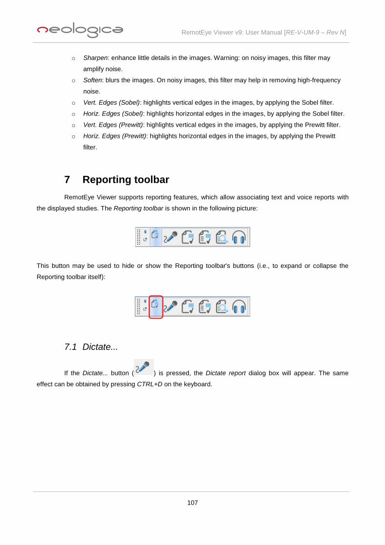
RemotEye Viewer v9: User Manual [RE-V-UM-9 – Rev N]
107
o Sharpen: enhance little details in the images. Warning: on noisy images, this filter may
amplify noise.
o Soften: blurs the images. On noisy images, this filter may help in removing high-frequency
noise.
o Vert. Edges (Sobel): highlights vertical edges in the images, by applying the Sobel filter.
o Horiz. Edges (Sobel): highlights horizontal edges in the images, by applying the Sobel filter.
o Vert. Edges (Prewitt): highlights vertical edges in the images, by applying the Prewitt filter.
o Horiz. Edges (Prewitt): highlights horizontal edges in the images, by applying the Prewitt
filter.
7 Reporting toolbar
RemotEye Viewer supports reporting features, which allow associating text and voice reports with
the displayed studies. The Reporting toolbar is shown in the following picture:
This button may be used to hide or show the Reporting toolbar's buttons (i.e., to expand or collapse the
Reporting toolbar itself):
7.1 Dictate...
If the Dictate... button ( ) is pressed, the Dictate report dialog box will appear. The same
effect can be obtained by pressing CTRL+D on the keyboard.

RemotEye Viewer v9: User Manual [RE-V-UM-9 – Rev N]
108
This window allows associating a vocal report with the currently displayed and selected study. In order to
record a new vocal report, it is sufficient to press the Rec button: the audio acquisition will begin and will
continue until the Stop button is pressed. RemotEye Viewer will record the voice of the user through an
appropriate microphone, which must be connected to the audio adapter of the client PC. The enabling of the
microphone input and the settings of the audio levels must be performed through the software mixer
provided with the driver of the audio adapter or with the Operating System.
The recorded vocal report can be saved to the server, by pressing the Save report button.
Also, the recorded vocal report can be played back by pressing the Play button. The slider located on the
bottom of the Dictate Report panel can be used to skip to a particular position in the recorded audio clip. If
the dedicated checkbox is marked the the audio file is compressed while uploading it to server.
The following keyboard shortcuts are supported when the Dictate Report dialog box is visible:
Ctrl+O = start recording, overwriting the eventually existing report. Pause recording when audio
recording is already active.
Ctrl+I = start recording, inserting the new recording into the current position of the eventually existing
audio report. Pause recording when audio recording is already active.
Ctrl+A = start recording, appending the new recording to the existing report. Pause recording when
audio recording is already active.
Ctrl+S = stop playing or recording.
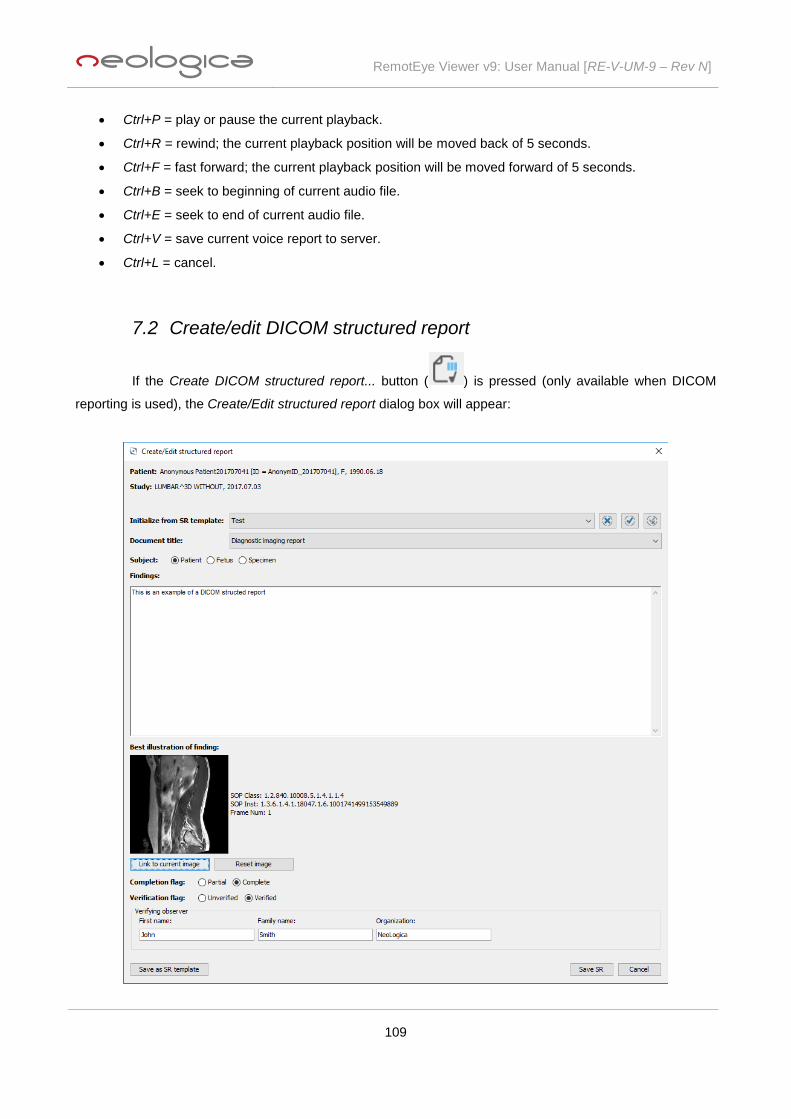
RemotEye Viewer v9: User Manual [RE-V-UM-9 – Rev N]
109
Ctrl+P = play or pause the current playback.
Ctrl+R = rewind; the current playback position will be moved back of 5 seconds.
Ctrl+F = fast forward; the current playback position will be moved forward of 5 seconds.
Ctrl+B = seek to beginning of current audio file.
Ctrl+E = seek to end of current audio file.
Ctrl+V = save current voice report to server.
Ctrl+L = cancel.
7.2 Create/edit DICOM structured report
If the Create DICOM structured report... button ( ) is pressed (only available when DICOM
reporting is used), the Create/Edit structured report dialog box will appear:

RemotEye Viewer v9: User Manual [RE-V-UM-9 – Rev N]
110
This window allows creating a new DICOM structured report (SR) for the current study. DICOM structured
report files are 100% DICOM-compliant files, hence they may be stored in a standard DICOM server or
PACS. This is a great advantage w.r.t. non-DICOM text reports, since the report will become an integral part
of the DICOM study on the PACS server.
In addition, DICOM structured reports can store a lot of structured information regarding the diagnostic report,
including an optional link to the most relevant image.
The Create/Edit structured report window allows manual entering of several data which are typical of a
DICOM structured report. In addition, the user may take advantage of the new SR templates functionalities.
Basically, the user may save the content of a typical structured report as a "SR template", by pressing the
Save as SR template button. He will then be able to re-use that typical content in successively-created
structured reports, by selecting the appropriate item from the Initialize from SR template drop-down list. This
will avoid time-consuming re-entering of typical content, and will speed-up the entire reporting phase.
When a SR template is selected in the Initialize from SR template drop-down list, it may be set as the default
template by pressing the Set selected SR template as default button ( ) and saving the user settings
through the Save user setting functionality as explained in paragraph 5.4.3. The Clear default SR template
button ( ) allows to delete this preference. Moreover, a SR template can be deleted by means of the
Delete selected SR template button ( ).
Once the DICOM Structured Report has been fully created, you can use the Save SR button to store it to the
server.
Existing DICOM structured reports previously created by RemotEye Viewer can be later edited pressing the
Edit existing DICOM structured Report(s)… button ( ) (also this item is only available when DICOM
reporting is used).
7.3 View DICOM Structured Report(s)...
If the View DICOM structured report(s)... button ( ) is pressed, the View structured report
dialog-box will be show and it will be possible to view the existing DICOM structured reports for the current
study (i.e., the study of the currently-selected image).

RemotEye Viewer v9: User Manual [RE-V-UM-9 – Rev N]
111
Depending on the viewer's configuration, one or more Report templates may be available. Selecting a given
report template will affect the way the DICOM structured report is presented to screen and printed to an
output sheet (which information is included in the report, how the text will look like, how each data is laid out
to screen / sheet, etc.).
In case multiple DICOM structured reports are available, a selection window will appear, allowing to choose
the desired SR. The displayed DICOM structured report may also be printed, through the Print… button.
By pressing the Print preferences... button, the SR print preferences dialog box will be shown, allowing to
define a custom header and footer for the printed structured report, including both images and texts:
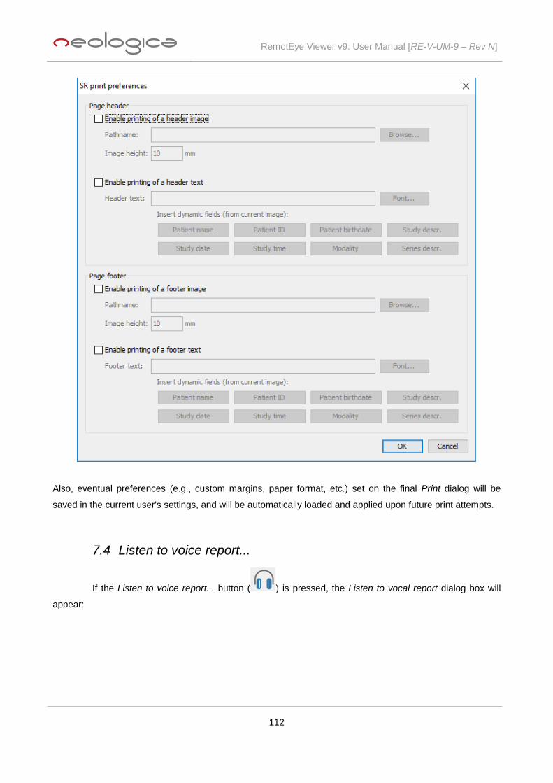
RemotEye Viewer v9: User Manual [RE-V-UM-9 – Rev N]
112
Also, eventual preferences (e.g., custom margins, paper format, etc.) set on the final Print dialog will be
saved in the current user's settings, and will be automatically loaded and applied upon future print attempts.
7.4 Listen to voice report...
If the Listen to voice report... button ( ) is pressed, the Listen to vocal report dialog box will
appear:

RemotEye Viewer v9: User Manual [RE-V-UM-9 – Rev N]
113
The voice report associated with the current study will be opened and eventually played back. Even in this
case, no modifications to the voice report can be performed. If the format of the voice report cannot be
directly managed by RemotEye Viewer, an external player application may be launched to play the report
audio file.
7.5 Plain-text reporting
Pressing the Transcribe toolbar button (when available), the Transcribe report dialog box will
appear.

RemotEye Viewer v9: User Manual [RE-V-UM-9 – Rev N]
114
This window allows associating a plain text report with the currently displayed and selected study. The
entered text report can be saved to the server, by pressing the Save report button, or it can be printed, by
pressing the Print report… button. Also, the corresponding vocal report can be called, by pressing the Vocal
report… button placed on top of the dialog box.
Pressing the View report toolbar button (when available), the text report associated with the current study will
be displayed, if available. No modifications to the report text can be made in this case. If the format of the
text report cannot be directly managed by RemotEye Viewer, an external viewer application may be
launched to display the report document.
8 Study panels
In RemotEye Viewer, each loaded study is displayed in its own dedicated study panel, which in turn
contains one or more series panels. The number and layout of series panels contained in the study panel
depends on the series tiling setting (i.e., the number of series columns and series rows).
Once the study is open, and several series are displayed on screen, you can maximize a given series (thus
switching to 1x1 series tiling and 1x1 image tiling) by double-clicking on it when the Select/Stack tool is
associated with the double-clicked mouse button. Then, when you are done with this image, you can double-

RemotEye Viewer v9: User Manual [RE-V-UM-9 – Rev N]
115
click again on it in order to return to the previous display mode, and all previously displayed images will be
restored on screen.
By default, multiple study panels (corresponding to multiple open studies) are arranged in a "tabbed" fashion.
However, it is possible to manually drag the tab title of each study panel to arrange and dock the panel
according to the user's preference (e.g., in a side-by-side fashion).
In addition, by right-clicking on the tab title related to a study panel, the following drop-down menu will
appear:
As can you see, this menu allows user to arrange study panels on screen in some different ways: study
panels can be grouped together in a tabbed fashion, they can be tiled horizontally or they can be tiled
vertically.
8.1 Study toolbar
Each study panel has its own study toolbar, containing buttons corresponding with study-level
options or operations. These operations change depending on the type of the study. Here is an example of
Study toolbar for a CT Study:
Here is an example of Study toolbar for a US Study:
When moving the mouse pointer over each single Study toolbar button, a tooltip text will appear, providing
additional information about the function of the underlying button.
The above examples show default study toolbars for CT and US studies respectively, with their typical
features. However, thanks to the Enable/disable functions button ( ), it is possible to manually
add/remove functionalities to these toolbars. Pressing this button, the following drop-down menu will appear:
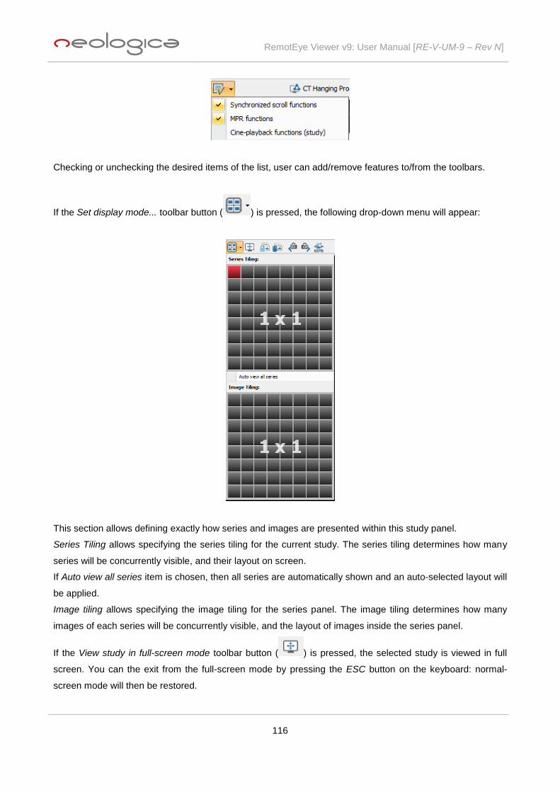
RemotEye Viewer v9: User Manual [RE-V-UM-9 – Rev N]
116
Checking or unchecking the desired items of the list, user can add/remove features to/from the toolbars.
If the Set display mode... toolbar button ( ) is pressed, the following drop-down menu will appear:
This section allows defining exactly how series and images are presented within this study panel.
Series Tiling allows specifying the series tiling for the current study. The series tiling determines how many
series will be concurrently visible, and their layout on screen.
If Auto view all series item is chosen, then all series are automatically shown and an auto-selected layout will
be applied.
Image tiling allows specifying the image tiling for the series panel. The image tiling determines how many
images of each series will be concurrently visible, and the layout of images inside the series panel.
If the View study in full-screen mode toolbar button ( ) is pressed, the selected study is viewed in full
screen. You can the exit from the full-screen mode by pressing the ESC button on the keyboard: normal-
screen mode will then be restored.

RemotEye Viewer v9: User Manual [RE-V-UM-9 – Rev N]
117
The Toggle automatic series synchronization... toolbar button ( ) allows synchronizing different CT or
MR series whose images (slices) were acquired moving in the same direction (acquisition planes with the
same orientation). The synchronization causes a scrolling through the images of these series, in such a way
all panels show images related to the same patient coordinates (where available). The reference coordinates,
at which all other panels are synchronized, are the ones of the currently selected image panel / series. In
order to support synchronization of all series, the image tiling of all series panels is automatically set to 1x1.
Once the Toggle automatic series synchronization... function is enabled, all scrolling operations will be
synchronized across the displayed series. In order to disable the Toggle automatic series synchronization...
function and the related locked scrolling among series, it is sufficient to click once again on the same toolbar
button.
The Toggle manual series synchronization... toolbar button ( ) allows manually synchronizing different
CT or MR series whose images (slices) were acquired moving in the same direction (acquisition planes with
the same orientation). This manual function is useful when it is necessary to manually set the initial "aligned"
state among several different series, and/or to synchronize scrolling among series belonging to different
studies, even acquired by different modalities: under these conditions, the Toggle automatic series
synchronization... function won't work. In order to use the manual series synchronization, the user must scroll
all relevant series in such a way they all show images related to the same patient coordinates. When
synchronized scrolling among several studies is necessary, the user shall select a given study, then click on
the arrow-shaped drop down button ( ), placed next to the Toggle manual series synchronization...
toolbar button. A drop-down menu will appear, allowing user to choose the other studies (in addition to the
current one) to synchronize with.
In case of cross-study manual synchronized scrolling, before activating the synchronization, the user must
scroll all relevant series of each study, in such a way they all show images related to the same patient
coordinates.
Once all relevant series have been scrolled in such a way to represent an initial "aligned" situation, it is
possible to press the Toggle manual series synchronization... button in order to lock scrolling of all those
series in a synchronized way. The scrolling position of each series in the moment when the Toggle manual
series synchronization... button is pressed is considered to be the initial reference point. In order to disable
the Toggle manual series synchronization... function and the related locked scrolling among series, it is
sufficient to click once again on the same toolbar button.

RemotEye Viewer v9: User Manual [RE-V-UM-9 – Rev N]
118
Load previous study in Worklist... ( ) and Load next study in Worklist... ( ) toolbar buttons are used
to load the previous or next study present in the Worklist window. The “previous” and “next” terms refer to the
order of studies as shown by the Worklist window, and are intended with reference to the currently-selected
study.
8.1.1 MPR (Multi-Planar-Reconstruction)
MPR (Multi-Planar Reconstruction) toolbar button ( ) allows performing a 3D volume
reconstruction and reslicing, when this operation is possible. The volume is built by stacking the slices of a
single series, which may have any acquisition orientation. The MPR function will then allow to "cut" the
volume by arbitrary planes, thus obtaining arbitrary slices out of the volume generated from the original
series. For instance, you will be able to obtain scrollable axial, sagittal, coronal or oblique views starting from
a single axial series.
In order to perform a MPR, it's necessary to start from a series having enough images to build a volume with
sufficient resolution. In addition, images must be correctly sorted by image position.
Moreover, if spacing between slices varies across images of the source viewing series or if source volume is
'skewed' , then RemotEye Viewer will display a warning message, as the generated MPR volume would be
distorted.
The figure below shows the four panels composing the Main MPR panel and the MPR toolbars:

RemotEye Viewer v9: User Manual [RE-V-UM-9 – Rev N]
119
As you can see, the default MPR view includes a 3D view (the top left panel in the figure above), and three
2D views, which contain the 2D slices extracted from the volume along the three defined cut planes.
Warning: the images resulting from Multi-Planar Reconstruction (MPR) are synthetic images
generated by a software algorithm. They are NOT images acquired directly by a medical device. As
such, their geometric and morphologic correctness, as well as the correctness of the measurements
taken on these MPR images, depend on the correctness of several orientation and spacing data
stored in the original DICOM datasets, in addition to on the correctness of the implemented
reconstruction algorithm. The viewer itself has no mean to ensure these input data are correct.
Hence, images coming from MPR shall be checked and treated in a very "critical" way by the
user/radiologist, and any conclusion coming from MPR images shall be carefully evaluated against
the original non-MPR images.
8.1.1.1 MPR 3D view
The MPR 3D view is the panel where the 3 cut planes within the volume are shown in a 3D scene.
Left-dragging with the mouse outside of the volume itself allows rotating the camera (i.e., the point of view)
around the volume. The toolbar located at the bottom of this 3D view allows associating several functions to
the mouse wheel (the association is only valid on this 3D panel), which are useful to move cut planes along
their perpendicular direction, as well as to rotate the camera (i.e., the point of view) of the 3D scene around
the volume. Finally, it is possible to reset the default view in this 3D scene.
8.1.1.2 MPR 2D views
Three different 2D views are present in the MPR window, corresponding to the three cut planes
which are working on the volume. Each 2D view has a border with a specific color, which allows associating
each 2D view with each cut plane displayed in the 3D view. Also, each 2D view shows the cut lines
representing the intersections between this cut plane and the other two cut planes. Also the cut lines respect
the color convention for cut planes. By left-dragging the end points of the cut lines, it is possible to rotate the
related cut plane, thus producing arbitrary oblique slices out of the volume. Clicking on the intersection point
between the cut lines, the "3D cursor effect" will be obtained (see paragraph 6.1.7), regardless the tool
associated, at the time, to the left mouse button. Whereas, clicking on any cut line's point, different from the
end point and the intersection point with the other cut line, it is possible to move the plane related to that line,
allowing user to easily find intersections with any point of the 3D volume. Finally, placing the mouse cursor
on a cut line (without clicking), and turning the mouse wheel, holding the Ctrl button down, that cut line will
be reduced or extended, depending on the rotation's direction, so the plane corresponding to it will be
zoomed in/out.

RemotEye Viewer v9: User Manual [RE-V-UM-9 – Rev N]
120
Moving the mouse pointer in the lower portion of a MPR 2D view, a specific toolbar appears, allowing to
show/hide cut planes on the 2D view, as well as to restore the view to the original cut orientation (i.e., axial,
sagittal or coronal).
Green and blue lines represent, respectively, coronal and axial planes which intersect the sagittal plane.
8.1.1.3 MPR main toolbar
The MPR main toolbar contains buttons which allow setting display mode for the MPR window,
viewing MPR in full-screen mode, resetting all cut planes, enabling Thick slab mode, and setting Thick slab
mode properties.
If you press the Set display mode... toolbar button, the following drop down menu will appear:
User can choose the desired display mode of the MPR window among several available options.
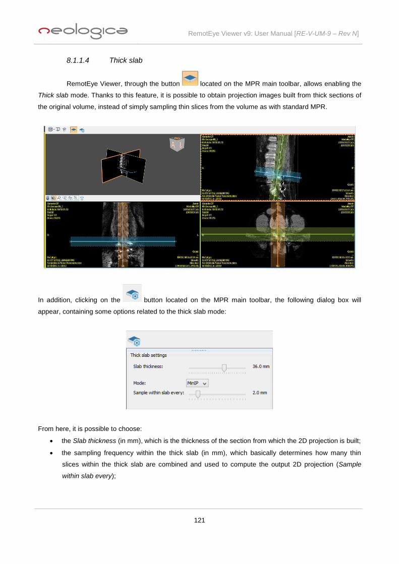
RemotEye Viewer v9: User Manual [RE-V-UM-9 – Rev N]
121
8.1.1.4 Thick slab
RemotEye Viewer, through the button located on the MPR main toolbar, allows enabling the
Thick slab mode. Thanks to this feature, it is possible to obtain projection images built from thick sections of
the original volume, instead of simply sampling thin slices from the volume as with standard MPR.
In addition, clicking on the button located on the MPR main toolbar, the following dialog box will
appear, containing some options related to the thick slab mode:
From here, it is possible to choose:
the Slab thickness (in mm), which is the thickness of the section from which the 2D projection is built;
the sampling frequency within the thick slab (in mm), which basically determines how many thin
slices within the thick slab are combined and used to compute the output 2D projection (Sample
within slab every);
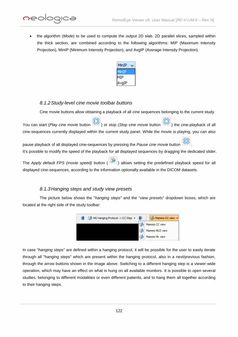
RemotEye Viewer v9: User Manual [RE-V-UM-9 – Rev N]
122
the algorithm (Mode) to be used to compute the output 2D slab. 2D parallel slices, sampled within
the thick section, are combined according to the following algorithms: MIP (Maximum Intensity
Projection), MinIP (Minimum Intensity Projection), and AvgIP (Average Intensity Projection).
8.1.2 Study-level cine movie toolbar buttons
Cine movie buttons allow obtaining a playback of all cine sequences belonging to the current study.
You can start (Play cine movie button ) or stop (Stop cine movie button ) the cine-playback of all
cine-sequences currently displayed within the current study panel. While the movie is playing, you can also
pause playback of all displayed cine-sequences by pressing the Pause cine movie button .
It's possible to modify the speed of the playback for all displayed sequences by dragging the dedicated slider.
The Apply default FPS (movie speed) button ( ) allows setting the predefined playback speed for all
displayed cine-sequences, according to the information optionally available in the DICOM datasets.
8.1.3 Hanging steps and study view presets
The picture below shows the "hanging steps" and the "view presets" dropdown boxes, which are
located at the right side of the study toolbar:
In case "hanging steps" are defined within a hanging protocol, it will be possible for the user to easily iterate
through all "hanging steps" which are present within the hanging protocol, also in a next/previous fashion,
through the arrow buttons shown in the image above. Switching to a different hanging step is a viewer-wide
operation, which may have an effect on what is hung on all available monitors. It is possible to open several
studies, belonging to different modalities or even different patients, and to hang them all together according
to their hanging steps.

RemotEye Viewer v9: User Manual [RE-V-UM-9 – Rev N]
123
The view presets drop-down menu allows for quick application of certain hanging presets to the current study
panel, with a single click. Normally, this menu displays the hanging views contained in the hanging protocols
matching with the current study, which can be applied at user's will.
For some particular kinds of studies, special hanging functions are available in the
view presets drop-down menu. For instance, in case of ultrasound "echo stress"
studies, user will be able to select hanging of series "by view" or "by stage". When
selecting a given "view" from the drop-down menu, RemotEye Viewer will display all
series related to that view, and will arrange the series tiling automatically in order to
contain all series related to that view. In the same way, selecting a given "stage" from
the drop-down menu, RemotEye Viewer will display all series related to that stage, and
will arrange the series tiling automatically in order to contain all series related to that
stage.
8.1.4 Share through Dropbox
The Share study through Dropbox ( ) toolbar button allows sharing the current DICOM study
with a remote recipient (e.g., for a consultation, second opinion, etc.) by exploiting the sending user's
Dropbox and a cloud viewing infrastructure based on RemotEye Viewer itself. This cloud-based viewing
infrastructure has been called "Exams Sharing Portal (ESP)".
Clicking on this button, a step-by-step Share through Dropbox wizard is started, as shown in the following
picture:

RemotEye Viewer v9: User Manual [RE-V-UM-9 – Rev N]
124
The first step of this wizard allows user to authenticate on the Exams Sharing Portal by entering email and
password related to his ESP account. If the user does not have a user account on the ESP yet, he can
create a new one selecting the appropriate option, as shown in the following screenshot:
Once user has successfully logged in to the ESP, RemotEye Viewer stores his login data, so that he will be
able to auto-login upon later usages of the Share through Dropbox functionality.

RemotEye Viewer v9: User Manual [RE-V-UM-9 – Rev N]
125
Clicking on the Next button, the page related to the second step of the wizard will appear:
Once user has authenticated on ESP, an attempt will be made to authenticate on Dropbox. If automatic
authentication succeeds, user can choose to proceed with that Dropbox account, as shown in the image
above. Otherwise, if automatic authentication on the user's Dropbox is impossible or fails, or user just wants
to associate a different Dropbox account, an authentication and authorization step takes place on Dropbox,
as you can see in the images below:

RemotEye Viewer v9: User Manual [RE-V-UM-9 – Rev N]
126
Once user has logged in to the ESP, and access to user's Dropbox is granted, RemotEye Viewer is ready to
upload current study's DICOM files to Dropbox.
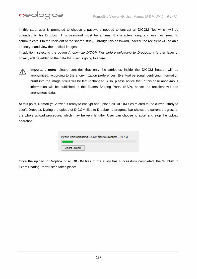
RemotEye Viewer v9: User Manual [RE-V-UM-9 – Rev N]
127
In this step, user is prompted to choose a password needed to encrypt all DICOM files which will be
uploaded to his Dropbox. This password must be at least 8 characters long, and user will need to
communicate it to the recipient of the shared study. Through this password, indeed, the recipient will be able
to decrypt and view the medical images.
In addition, selecting the option Anonymize DICOM files before uploading to Dropbox, a further layer of
privacy will be added to the data that user is going to share.
Important note: please consider that only the attributes inside the DICOM header will be
anonymized, according to the anonymization preferences. Eventual personal identifying information
burnt into the image pixels will be left unchanged. Also, please notice that in this case anonymous
information will be published to the Exams Sharing Portal (ESP), hence the recipient will see
anonymous data.
At this point, RemotEye Viewer is ready to encrypt and upload all DICOM files related to the current study to
user's Dropbox. During the upload of DICOM files to Dropbox, a progress bar shows the current progress of
the whole upload procedure, which may be very lengthy. User can choose to abort and stop the upload
operation.
Once the upload to Dropbox of all DICOM files of the study has successfully completed, the "Publish to
Exam Sharing Portal" step takes place:

RemotEye Viewer v9: User Manual [RE-V-UM-9 – Rev N]
128
Here, it is necessary to enter the email address of the recipient, which will be used to send him a notification
email, informing him about the availability of a shared study for him on the ESP. This email will provide the
recipient with an appropriate link, as well as login information, which will enable him to access the exam's
images. Also, this email address will be used to create the recipient's user account on ESP, if not already
existing. It is possible to send the exam password to the recipient directly by email, by selecting the Transmit
exam password to recipient by email option.
Warning: transmitting the exam password to the recipient by email may be insecure. If you want to
ensure maximum security, please leave this option unselected, and transmit the password to the
recipient through a different mean (e.g., phone call).
Finally, user can type a note for the recipient of the shared exam through the appropriate box.
At this point, clicking on the Next button RemotEye Viewer will publish the current study to the Exams
Sharing Portal (ESP).
Once the study has been successfully published to ESP, user can choose whether to use one of his existing
credits (if available) to unlock viewing of the study, or to purchase new credits to unlock the study on behalf
of the recipient, or rather to leave the recipient the task of unlocking the study at a later stage.

RemotEye Viewer v9: User Manual [RE-V-UM-9 – Rev N]
129
Once a user has unlocked a shared exam, that exam will be online and viewable (by both the sender and the
recipient) as long as the sender will keep it in his own Dropbox, for an unlimited number of times.
Once the unlock step has been done or skipped, the exam sharing operation is complete, and RemotEye
Viewer provides a final summary:
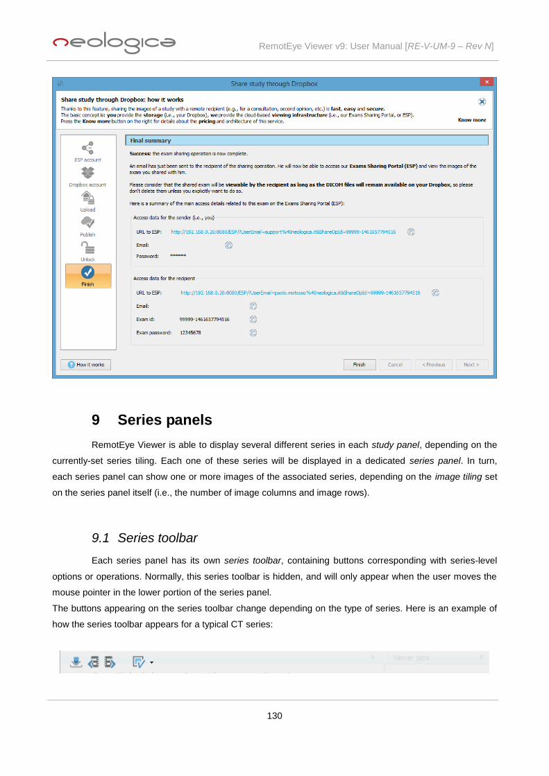
RemotEye Viewer v9: User Manual [RE-V-UM-9 – Rev N]
130
9 Series panels
RemotEye Viewer is able to display several different series in each study panel, depending on the
currently-set series tiling. Each one of these series will be displayed in a dedicated series panel. In turn,
each series panel can show one or more images of the associated series, depending on the image tiling set
on the series panel itself (i.e., the number of image columns and image rows).
9.1 Series toolbar
Each series panel has its own series toolbar, containing buttons corresponding with series-level
options or operations. Normally, this series toolbar is hidden, and will only appear when the user moves the
mouse pointer in the lower portion of the series panel.
The buttons appearing on the series toolbar change depending on the type of series. Here is an example of
how the series toolbar appears for a typical CT series:

RemotEye Viewer v9: User Manual [RE-V-UM-9 – Rev N]
131
Here is an example of the series toolbar looks like for a cine-sequence of a US study:
When moving the mouse pointer over each single toolbar button, a tooltip text will appear, providing
additional information about the function of the underlying button.
The above examples show the two default series toolbars for CT and US studies with their typical features,
however thanks to the Enable/disable functions button ( ) is possible to add/remove functionalities to
these toolbars. In particular user is able to activate cine-playback functions also for series whose toolbars, by
default, don't include this kind of features. Pressing this button, the following drop-down menu will appear:
The Load original version of this series toolbar button ( ) allows loading the original version of the
current series if the series currently contains a lossy version of the images. If, when pressing this button, the
series already contains the original version of the images, then the following message is shown by
RemotEye Viewer:
Please consider that this toolbar button (and the associated feature) is only available when the back-end
provides adequate support for it, and the Load a lossy version of the images first option is enabled in the
Settings --> Loading preferences.
The Previous series toolbar button ( ) and Next series toolbar button ( ) are used to scroll to the
next or previous series, if multiple series are currently loaded into RemotEye Viewer.

RemotEye Viewer v9: User Manual [RE-V-UM-9 – Rev N]
132
9.1.1 Series-level cine movie toolbar buttons
Cine movie buttons allow obtaining a cine-playback of all images / frames belonging to the current
series or multi-frame sequence.
You can start (Play cine movie button or Ctrl+P) or stop (Stop cine movie button or Ctrl+S) the
playback of the movie. While the movie is playing, you can also pause playback by pressing the Pause cine
movie button (or again CTRL+P).
It's possible to modify the speed of the playback by dragging the dedicated slider. Next to the slider the
actual speed of the playback is indicated.
The Apply default FPS (movie speed) button ( ) allows setting the predefined playback speed for a
given cine-sequence (according to the information coming from the DICOM dataset, if available.
Pressing the Play once button ( ) the frames 1 to N (where N is the total number of frames in the current
series) are displayed in rapid sequence, then the playback is stopped.
Pressing the Looping button ( ) the frames 1 to N are displayed in rapid sequence, then the playback
begins again from frame 1 and so on (frame sequence: 1,2,…,N,1,2,…,N,1,2,…).
Pressing the Sweeping button ( ) the playback sequence is as follows: 1,2,…,N,N-1,N-2,…,2,1,2,…,N…
(forward and backward).
9.2 Pop-up menu
RemotEye Viewer features a pop-up menu on images, which allows a fast selection of common
tools, functionalities and options.
In order to show the pop-up menu it is necessary to right-click on a non-empty image panel while keeping
the Ctrl key of the keyboard pressed. Since RemotEye Viewer allows a flexible association of image tools to
both left and right mouse buttons, pressing Ctrl on the keyboard is necessary, in addition to right-clicking, to
display this pop-up menu.
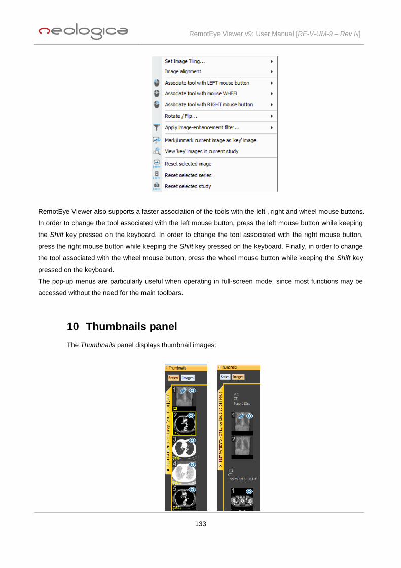
RemotEye Viewer v9: User Manual [RE-V-UM-9 – Rev N]
133
RemotEye Viewer also supports a faster association of the tools with the left , right and wheel mouse buttons.
In order to change the tool associated with the left mouse button, press the left mouse button while keeping
the Shift key pressed on the keyboard. In order to change the tool associated with the right mouse button,
press the right mouse button while keeping the Shift key pressed on the keyboard. Finally, in order to change
the tool associated with the wheel mouse button, press the wheel mouse button while keeping the Shift key
pressed on the keyboard.
The pop-up menus are particularly useful when operating in full-screen mode, since most functions may be
accessed without the need for the main toolbars.
10 Thumbnails panel
The Thumbnails panel displays thumbnail images:

RemotEye Viewer v9: User Manual [RE-V-UM-9 – Rev N]
134
If the Series option button is selected on the Thumbnails panel, then each thumbnail image will represent a
series currently loaded in RemotEye Viewer, and the number of displayed thumbnail images for each study
will be equal to the number of series currently loaded in RemotEye Viewer for that specific study. The
thumbnails are grouped by study.
On the other hand, if the Images option button is selected on the Thumbnails panel, then each thumbnail
image will represent a single image currently loaded in RemotEye Viewer, and the number of displayed
thumbnail images for each study will be equal to the total number of images currently loaded in RemotEye
Viewer for that specific study. Also in this case the thumbnails will be grouped by study and series.
Drag&drop of images or series from the Thumbnails panel to the study panel(s) is supported. You can also
select multiple thumbnails in the Thumbnails panel, by the Windows-usual Shift-click or Ctrl-click, and then
dragging & dropping all selected images or series (depending on the active mode) to the Study panel.
Double-clicking on a thumbnail will load the double-clicked series or image into the currently selected image
panel. Double-clicking on a series thumbnail while pressing the Alt key on the keyboard will load the study
panel with the scene starting at the double-clicked series. Double-clicking on the tab related to a particular
study, will hang the study, following the rules of the first matching hanging protocol.
When the proper option is enabled in the Settings section (under Display preferences) , the thumbnails will
be marked by symbols to identify the series or images displayed on the main study panel(s): while the
symbols identify the series or images currently displayed (i.e., hung on screen) in RemotEye Viewer, the
symbol indicates the currently-selected series.
The thumbnail panel may be hidden or shown by clicking on the pin icon appearing at the top right of the
panel itself.
11 Viewer jobs panel
In the Viewer jobs panel the progress of the jobs is shown. The image below shows an example of
DICOM files loading.
12 How to report issues
In case you encounter issues or you detect a malfunctioning while using the RemotEye Viewer
software, please report the problem to the NeoLogica Support Staff.

RemotEye Viewer v9: User Manual [RE-V-UM-9 – Rev N]
135
NeoLogica uses a ticket-based online support system. In order to report a problem, please browse to the
following web address:
https://www.neologica.it/Support
You will then be able to open a new "support ticket", and specify the details of the issue you have detected.
The NeoLogica Support Staff will analyze the reported issue and will reply promptly, then making every effort
to solve the issue in the shortest possible time.
13 Acknowledgments
RemotEye Viewer relies on the CharLS library in order to decode JPEG-LS-compressed images.