remote control helicopter - welcome - college of ... in this document, we will be discussing our...
TRANSCRIPT

Remote Control Helicopter
By
Abdul Aldulaimi, Travis Cole, David Cosio, Matt Finch,
Jacob Ruechel, Randy Van Dusen
Team 04
Engineering Analysis Document
Submitted towards partial fulfillment of the requirements for
Mechanical Engineering Design I – Fall 2013
Department of Mechanical Engineering
Northern Arizona University Flagstaff, AZ 86011
Table of Contents
1. Introduction .....................................................................................................................3
2. Problem Description ........................................................................................................3
3. Helicopter Description .....................................................................................................3
4. Analysis Overview ..........................................................................................................4
5. Blade Analysis.................................................................................................................4
6. Landing Gear Analysis ....................................................................................................7
7. Modeled U13A ................................................................................................................9
8. Gantt Chart .................................................................................................................... 10
9. Conclusion .................................................................................................................... 11
10. References ..................................................................................................................... 12
Introduction In this document, we will be discussing our engineering analysis of the U13A remote controlled
helicopter. However, before discussing the engineering analysis, we will be giving a brief overview of
the project in which we have been tasked with completing, which is the scaling of a remote
controlled helicopter. Lastly, we will review our Gantt chart and give an update as to where our
team is at and what is coming in the near future.
Problem Description
Our client is Dr. Kosaraju, an instructor at Northern Arizona University. He has given our
team the task of purchasing and scaling a remote controlled helicopter. For this task he requested
a helicopter whose length is approximately 10 inches. Our ultimate task is to successfully scale
this helicopter by 1.5. In the process of scaling, we will be analyzing the design of the helicopter
itself to see what could be changed to help better the performance of the helicopter.
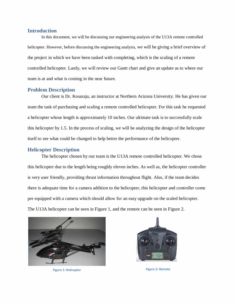
Helicopter Description
The helicopter chosen by our team is the U13A remote controlled helicopter. We chose
this helicopter due to the length being roughly eleven inches. As well as, the helicopter controller
is very user friendly, providing thrust information throughout flight. Also, if the team decides
there is adequate time for a camera addition to the helicopter, this helicopter and controller come
pre equipped with a camera which should allow for an easy upgrade on the scaled helicopter.
The U13A helicopter can be seen in Figure 1, and the remote can be seen in Figure 2.
Figure 2: Remote Figure 1: Helicopter

Analysis Overview For analyzing the U13A helicopter, our team wanted to focus on three main sections of the
helicopter that we deemed important and worth analyzing. As a result, we will be discussing the
engineering analysis on the blades, and the landing gear. We want to investigate the blades to ensure that
when we scale the helicopter they are able to function properly without failure, and the landing gear to
ensure that hard impacts will be withstood by the helicopter.
Blade Analysis
The analysis of the blades of the helicopter began with testing the original U13A
helicopter for its lift capabilities. The weight of the un-scaled helicopter was determined to be
0.3078 pounds. To determine the maximum load that could be lifted, the weight of the load on
the helicopter was gradually increased, until the helicopter could no longer achieve flight; this
maximum load was found to be 0.0745 pounds amounting to a total lift force of 0.3823 pounds,
or 24.2% more than the helicopter’s weight. For the scaled helicopter design, it is desired for the
lift to weight ratio to be increased with respect to the un-scaled helicopter.
In order to begin analysis on the scaled helicopter, several assumptions had to be made.
The first assumption was for the total weight of the helicopter to be three times larger than that
of the un-scaled helicopter, for a total of 0.9234 pounds. Next, several assumptions regarding
the dimensions of the final blade were made. The same blade shape as the un-scaled helicopter
would be utilized in the scaled design, however, the blade is not uniform throughout its length
and the geometry must first be simplified before calculations can be made. The total length of
the blades would be scaled up to at least 7.5 inches, somewhat greater than the 1.5 times scaling
requirement; this is in order to account for the rapid weight increase that occurs when up-scaling.
Similarly, the chord length, or width of the blade, would be scaled up to an average of 1.2 inches
across. The thickness of the blade will be at least 0.1 inches. After assuming the rotor geometry,
the coefficients associated with the lift and drag forces were also assumed. For helicopter blades

of similar size and shape, the coefficient of lift can range from 0.1 to 0.7 [6]; for this reason, the
average value from this range, 0.4, was used for the coefficient of lift. In order to accurately
assume a value for the coefficient of drag on the blades, the value of 0.04 for a fully streamlined
body was considered, but then increased to 0.1 in order to embed a design factor into the
calculations [5]. In addition to the assumptions listed above, several more key assumptions were
made to complete the analysis and will be mentioned throughout the section. Figure 3 below
shows a free body diagram of the basic forces occurring while the helicopter is in flight.
Figure 4: Free body diagram of the helicopter in flight.
The first calculation made is for the power supplied to the rotor. Assuming that the
battery pack can deliver 7.4 volts and can supply a current of 30 amps, the power is calculated in
the following equation:
( )( )
where:
V→ voltage,
I→ current.
The resultant 0.298 horsepower comes from reasonable assumptions for the battery voltage and
current that can be achieved from a variety of different lithium polymer cell configurations.

After calculating the power, the lift force created by the rotor was calculated [2]. First,
the power loading is calculated as:
(
)
.
The thrust loading can then be calculated using the formula:
.
And finally, the lift can be calculated as:
(
) ( ) .
In order to calculate the drag force on the helicopter blades, the angular velocity must
first be known. For helicopters of similar size to the scaled helicopter, the average angular
velocity is 1600 RPM, or 167.6 rad/s [3]. This gives us a maximum tip velocity of [4]:
(
) (
) .
The following equation relates the drag force to air density, velocity, area, and the
coefficient of drag [4]:
( )
( ) (
)
where:
→ Coefficient of drag,
→ Density of air at 7000 feet,
→ Area of the blade perpendicular to the drag,
→ Average blade velocity.

The final step in the blade analysis is to analyze the stresses that will develop along the
blades during flight. Modeling each blade as a cantilever beam, a bending moment due to the lift
force will be the dominant stressor during flight. The bending due to the drag force is ignored in
this analysis because aspect ratio suggests that very little stresses will occur in that direction. For
a lift of 4.02 lbs., each blade will experience a distributed load across the length amounting to
1.005 lbs. To ensure that each of the blades are designed to survive the loading, the stresses will
calculated using a point load of the total lift at the tip of the blade instead of the distributed load
that is truly there. Using simple statics, the moment is given by:
( )( )
After calculating the maximum moment, the stress in the beam can be calculating using the
following equation:
( )( )
( ( )
At this stress level, all of the common RC helicopter blade materials will all handle the
stresses without a problem. Because of this, the standard high strength polypropylene was
chosen for its low cost, low density, high strength, and high impact resistance. Carbon fiber,
fiber glass, and wood are lighter weight, however have a higher cost and are much more brittle
than the plastic. Aluminum has an unnecessarily high strength and weight to be a practical
application on a helicopter of this size.
Landing Gear Analysis The landing gear was deemed a very important subject for engineering analysis. This is due to the
fact that our team is going through a lot of effort to successfully scale the U13A helicopter, and if upon

use of the helicopter, it failed due to landing impact that would be a serious problem. So here is the
analysis for the landing gear.
Besides power plant and thrust systems one of the most important pieces on any
helicopter is a reliable landing gear. The landing gear provides a stable means of support for the
helicopter when landing. The material for the skid support structure, as seen in Figure 4 below, is
Ethylene-Vinyl Acetate (EVA). EVA is a very resilient plastic with excellent shock absorbing
properties. The ultimate compressive strength for EVA is 1450 PSI and the tensile strength is
2000PSI [1]. Using a strong shock absorbing material will ensure that a minimum amount of
force from a landing will be imparted to sensitive systems like the motors or battery. With more
forceful landings it will be advantageous if the landing gear breaks on impact so the forces will
be diverted into breaking the members and not directly into the aircraft.
Figure 4: New upscale landing gear Figure 5: Static analysis
Figure 4 shows the Team’s updated landing gear for the 1.5 scaled helicopter. The skid
support structures which are the thicker pieces attached to the rods, have a constant cross
sectional area of 0.15 in2. To analyze whether this landing gear can absorb the shock the Team
must find the impact force and use the cross section area to get a stress. By comparing the stress

in the member to the compressive strength of EVA the Team can assess whether the landing gear
can survive a fall from a specified height. The Team has chosen to analyze the landing gear
falling from a height of 6 ft. The chosen weight was slightly over 3 times the original weight.
This is well over the 1.5 scale, however the Team chose to go 3 times the original weight so as to
take into account any increases in weight from materials selection or add ons such as cameras.
The Team is using the Impact Force equation which is as follows:
. In the equation to
the left W is the weight of the object in pounds, h is the height as which the object is dropped in
feet, and s is the slow down distance in feet. The impact force is measured in pounds. The Team
found the slow down distance to be 0.2 inches which measures to 0.0167 feet. This distance is
measured from the testing of the displacement of the original landing gear. Through the use of
the impact force equation the impact force is found to be 172.8 lbs. By diving among the four
vertical members the force turns into 43.2 lbs. Using this vertical force and doing some statics
analysis as shown in Figure 5 above, we can see that the force that compresses the member in the
landing gear is 40.6 lbs. The next step is to find the stress in the member and assess whether it
can handle the impact. Stress is found using the equation:
. The stress is found to be 270.67
PSI. This stress is well below the ultimate compressive strength of 1450 PSI so it is safe to
assume that this landing gear will survive a six foot fall with an abrupt stop.
Modeled U13A
Over the past three weeks we have started to model our helicopter as you can see in
Figure 6. This model is just about done we are missing the fins in the back and the tail supports.
In the upcoming weeks we will be scaling this model by 1.5 and making changes to the design of
the helicopter to make it perform better. These changes will consist of a new landing gear, new
blades, new gear ratio, and changing the pivoting angle of the blades. While we chose all the new

designs we will finish all of our analyses on the helicopter and finish selecting the material that
the new parts will be made out of.
Figure 6: SolidWorks model of the U13A helicopter
Gantt Chart
The project plan is still on track based on our predicted dates. We are approaching our
final milestone which is the final design. We are continuing the process of assembling the
helicopter in solid works and it is almost fully assembled. For the design improvements, the team
decided to continue working on the analysis part of the landing gear, and blades. Each of these
individual parts took time to analyze because of its complex U13A design. The team made sure
everyone did research on their specific part in order to start the analysis. The final task is to
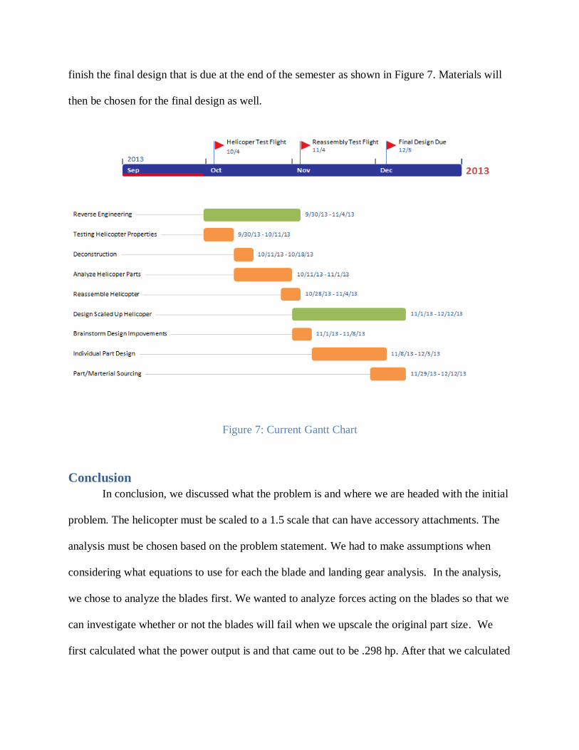
finish the final design that is due at the end of the semester as shown in Figure 7. Materials will
then be chosen for the final design as well.
Figure 7: Current Gantt Chart
Conclusion
In conclusion, we discussed what the problem is and where we are headed with the initial
problem. The helicopter must be scaled to a 1.5 scale that can have accessory attachments. The
analysis must be chosen based on the problem statement. We had to make assumptions when
considering what equations to use for each the blade and landing gear analysis. In the analysis,
we chose to analyze the blades first. We wanted to analyze forces acting on the blades so that we
can investigate whether or not the blades will fail when we upscale the original part size. We
first calculated what the power output is and that came out to be .298 hp. After that we calculated

the lift force created by the rotor and that is .2428 hp/ft2. We then calculated the thrust loading
to be 13.48 lbs/hp. Finally, after calculating all those results we calculated the lift force to be
4.02 lbs. To ensure that each of the blades are designed to survive the loading, the stresses will
calculated using a point load of the total lift at the tip of the blade instead of the distributed load
that is truly there. The moment came out to roughly be 7.5 in-lb and the stress in the beam is
3768.75 PSI. Polypropylene was chosen for our material on the blades because of its low cost
and lightweight. The second analysis was the landing gear. We chose to analyze this because the
landing is the most important thing to keep in contact because it has many components; such as,
the motor, battery, rotors, and gears. These are all important when considering a soft or hard
landing. Again, we had to make assumptions for that and we chose a height of six feet. The result
of the impact force is 172.8 lbs. Dividing that number by four we go that each vertical member
of the skids to be 43.2 lbs. After calculating the impact force we calculated the stress on the skids
to be 270.67 PSI. This stress is well below the ultimate compressive strength of 1450 PSI so it is
safe to assume that this landing gear will survive a six foot fall with an abrupt stop. In addition,
we discussed the model of the U13A helicopter and colored in the parts that still needs work.
Lastly, the project plan is to continue on what we are modeling in solid works and to also have a
fully up scaled helicopter for the final design.
References
[1] http://www.ereva.com/ft/EVA.pdf
[2] Heli Chair, 2011, “Aerodynamics 101”, from http://www.heli-
chair.com/aerodynamics_101.html
[3] Heliguy, 2010, “Remote Control Helicopters FAQ”, from
http://www.heliguy.com/nexus/newbie.html
[4] Seddon, J., 1990, Basic Helicopter Aerodynamics, Mackays of Chatham, Chatham, Kent.

[5] Squire, J., 2010, “Airfoil lift and drag coefficients”, University of Maryland Baltimore
County, from http://www.csee.umbc.edu/~squire/cs455_lairfoil.shtml
[6] Wolfgang, R.C., 2006, “Lift Produced by Multi-Blade Heads”, from
http://rc.runryder.com/helicopter/t276865p1/