remote control 1975: now you can monitor almost anything.€¦ · 35 transmitter remote control-a...
TRANSCRIPT

19-5
BROADCAST MANAGEMENT; ENGINEERING
REMOTECONTROL 1975:
Now You Can MonitorAlmost Anything.

Models anc actresses devotecountless hours to making their skinas flawless and beautiful as possible.
But lines and glitchescaused by videotape dropouts canmake everything look ugly. Andthat's distracting and irritatingto viewers.
So in 1965, 3M introduceda quadruplex color dropoutcompensator that has since becomethe standard of the industry.Today, all three networks andthousands of TV stations across thecountry rely on 3M Brand ColorDOC's to bring viewers betterpicture quality.
But what have we done foryou lately?
A lot. In fact, we've justdeveloped five brand-new low-costproducts for broadcast, industrial andeducational needs.
First, there's a remarkablyinexpensive Colo.- Bar and SyncGenerator that produces an NTSC8 -bar pattern and all sync signals.
Next, there are threeDistribution Amplifiers (Pulse DA,Subcarrier DA and Analog DA)designed for any video application.
Our new mini ProcessingAmplifier has a full set of front panelcontrols, plus a built-in pulse -crossgenerator with automatic brighteningthat allows the use of any inexpensivemonitor to examine the criticalhead switch area for tracking andskew adjustments.
Our new 10 input BridgingVideo Switcher has momentary-
contact illuminated buttons with anaudio DA to eliminate loading,plus remote capability.
And finally, there's our
advanced Digital Automatic GainCant -al that can be used in anya ppl coticn where sucden andundesiratle signal level changesoccur, without incurring theunacceptable effects usuallyassociated with AGC circuitry.
A lot of companies wouldbe taking it easy if they were inour shoes But we don't intend to aslong os there are more problemsto clear up.
We don't quitWhew we're ahead.
VIDEO PRODUCTS
Mincom Division aCOMPANY3M CENTER SAINT PAUL, MINNESOTA 55701
Circle 108 on Reader Service Card

NOW . . .
we've addedcrystal -controlled
off -the -air UHF tuning.
For those critical UHF requirements, DYNAI R'snew crystal -controlled VT-4BU plug-in tuner assuresfrequency stability of 0.005% on any specifiedUHF channel. In addition, all channels from 14through 83 may be manually tuned. An AFC lockmay be used, if desired, for additional stability onthese channels.
BROADCASTERS find the new UHF tuner andthe RX-4B DYNA-TUNE Demodulator an ideal
VT-4BUPlug-in UHFTuner
DYNA-TUNE
FT -4B Plug-inFixed VHF Tuner
combination for remote broadcast monitoring,especially so when an optional video chopper isadded for checks of modulation percentage.
Adjustable color compensation results in a nearlyideal response curve . . . particularly important inclient room applications where color quality is
critical.CATV OPERATORS find the R X-4B/VT-4BU
an excellent choice for off -air UHF pick-ups andfor measurements of systems performance.
Separate visual and aural IF strips, uniquetrapping circuitry to eliminate the possibility of920 kHz beats, low differential phase and gaincharacteristics, standard receiver envelope delayresponse are a few of the performance features.
And, of course, there's the overall operationalstability which results from DYNAI R's high -qualityand solid-state reliability. Conservative design, liber-al use of integrated circuitry and glass -epoxy etchedboards make it so.
Write today for complete details to home officeor eastern region office - P. 0. Box 17342, DullesInternational Airport, Washington, D. C. 20041;telephone (703) 471-4078.
VT -4B-1 Plug-inVariable VHF/UHF Tuner
Circle 101 on Reader Service Card
APRIL, 1975-BM/E
PRICES:
VT-4BU Tuner $ 300.00
RX-4B/VT-4BU 1750.00
RX-4B/FT-4B 1820.00
RX-4B/VT-4B-1 1720.00
Optional Chopper(CK-4B) 150.00
Also available for export standards.
DYNAIR Electronics, Inc.6360 Federal Blvd., San Diego, Ca. 92114Phone: 714-582-9211; TWX: 910-335-2040
3

This month's cover is not as farfetched as it might seem sincesecurity data can be sent re-motely. The message won't bestyled quite so graphically,however, since we substituteda Vidifont system for the moretypical CRT terminal, throughthe courtesy of Bob Estony ofCBS Laboratories. Photo-grapher was Joseph Gallagherof CBS Labs.
BROADBANDINFORMATION SERVICES, INC.274 Madison Ave.New York, N.Y. 10016212-685-5320
EditorJames A. Lippke
Associate EditorRobin Lanier
Washington EditorM.L. Hollowell
Contributing EditorRobert Wollins
Assistant EditorDjuna Zelimer
Art DirectorGus Sauter
Production ManagerHelen Horan
FCC CounselPittman Lovett Fordand Hennessey
PublisherCharles C. Lenz Jr.
BROADCAST MANAGEMENT ENGINEERING
APRIL 1975/VOLUME 11/NUMBER 4
6 Broadcast Industry NewsWestinghouse & Harris Corp. show off their all solid-state transmitters
20 FCC Rules & RegulationsFCC Adopts New Fees
24 Studio Lighting and the Energy ProblemPart ll discusses how maintenance can help
28 Film Is Still In ThereAn up-to-date report on the things film still does especially well
32 Also: Today's 16mm Cameras Are Designed for TV News Gathering
35 Transmitter Remote Control-A Status ReportA survey for managers and engineers on what can be accomplishedtoday
39 Remote Control Operation of Radio Station WFUN42 Remote Control of WWL-AM-FM-TV Transmitters
48 The Great Idea ContestNew rules, new prizes and 5 new ideas.kick off the 1975 contest
56 The Directional Antenna PatternHow to calculate theoretical directional antenna patterns
67 Broadcast EquipmentNew and significant products
71 Letters/FeedbackSome thoughts on saving energy; a correction on timebase corrector information; letters
74 New LiteratureUseful reading materials
CM/E: A supplement for those with cable interest following page 74:Programming Ideas that Pay Off; Preview of NCTA Convention
B PABM/E, BROADCAST MANAGEMENT/ENGINEERING, is published monthly by Broadband InformationServices. Inc. All notices pertaining to undeliverable mail or subscriptions should be addressed to 274Madison Ave., New York. N.Y. 10016. BM/E is circulated without charge to those responsible for station
operation and for specifying and authorizing the purchase cf equipment used in broadcast facilities. These facilitiesinclude AM, FM, and TV broadcast stations; CAN systems; EN stations; networks and studios; audio and videorecording studios; consultants, etc. Subscription prices to others: $15.00 one year. $25.00 two years. Foreign: $20.00one year. $35.00 two years. Foreign Air Mail: additional $24.00. Copyright' 1975 by Broadband Information Services,Inc., New York City. Controlled circulation postage paid at East Stroudsburg, PA.
4 APRIL, 1975-BM/E

BORDERLINE GENERATORS
STARTING WITH A NORMAL KEY SIGNAL,THE GV3 BORDERLINE WILL
PROVIDE A BLACK BORDER AROUNDA MATTED TITLE CR
PRODUCE A DRO?SHADOW EFFECT ONLETTERING OR TITLING OR
PRODUCE OUTLIVE LETTERING FROMA SOLID TITLE SOURCE
DESCRIPTION
Grass Valley Group Borderline Generators are used to add borders to captions ard tidesfrom camera video sigials or character generators. The added bc.rcers greatly inhance the in-sert visibility, and are particularly effective in situations requir ng a white insert into a pre-dominantly white scene.
Model 3271 is fo- use with GVG 3400 Series switching systerrs ard 900 Series spec al ef-fects equipment. The keying circuitry in the special effects amplif er is Ltilized for the insertingfunction, thereby enabling effects such as wipe key between bordered inserts.
Model 3272 is fo- use with special effects equipment of other manufacturers. It prcvidesa widened key signal cutput which can be"connected to the external key input of most specialeffects systems. The widened key output, together with a slightly delayed (H and V) title videosignal, is used to achieve the border effect.
Model 3273 is a complete system which provides dordered inserts into a composite videosignal, such as at the cutput of a switching system. The unit is entirely self-contained and re-quires no horizontal o- vertical driving signals.
Borderline Generators are available for NTSC, PAL, PAL -M, End CCIR standards.
THE GRASS VALLEY GROUP, INC.
Station Plaza EastGREAT NECK, NY 11021(516) 487-1311
4419 Van Nuys Blvd, Ste 3E7SHERMAN OAKS, CA 91413(213) 930-6172
GA TEKTROAIX CONPANY
1644 Tullie Cir, NEATLANTA, GA 3C329(404) 634-0521
P.O. Boz 4E2MABANK, -X 75147(214) 8E7-1181
810 W Bristol StreetELKHART, IN 4E511(219) 264-0931
APRIL, 1975-BM/E 5

BROADCAST INDUSTRY
'VIES/ITSRadio, TV, Cable-All ToGrow Thru '85, Says CoxStrong growth over the next ten yearsfor radio, television, and cable, with-out serious competition betweenbroadcasting and cable, is the consen-sus prediction of a large group ofexperts queried in a comprehensivesurvey by Cox Broadcasting Company,released late in February. Total advolume, the survey predicted, will rise7% to 8% a year, going from thepresent $25 billion to about $60 billionin 1985. The TV and radio shares ofthis amount will both rise, TV goingfrom 19% to 22% of the total, radio'sfrom 6% to 8%. Cable's share of theadvertising dollar will rise too, but itwill still be only about 0.7% of the totalby 1985. Cable penetration will gofrom the present 13% of all homes toabout 29% in 1985. The average cablesystem will get 60% of its revenue fromsubscriptions, 30% from pay cable, andonly 10% from advertising.
NAB Asks Court To AffirmRule Vs. FCC on FairnessThe National Association of Broad-casters has strongly urged the U.S.Court of Appeals to reaffirm a decisionwhich overturned a FCC ruling that theNational Broadcasting Company vio-lated the fairness doctrine in the pro-gram, "Pensions: The Broken Prom-ise." A rehearing on the question hasbeen granted by the Court at the requestof Accuracy in Media, the organizationthat filed the original complaint againstNBC. The NAB brief argues that theCourt's original ruling was correct, insaying that the FCC should have limit-ed itself to judging the reasonablenessand good faith of NBC's decision to runthe program.
NAB Petitions Court OnRefund of FCC FeesIn another plea to the U.S. Court ofAppeals, the National Association of
All Solid -State Transmitter Unveiled
At the introduction in Quincy, Illinois, of Harris Corporation's M-1, all solid-state 1 kWAM broadcast transmitter, were (from left) Gene T. Whicker, vice president andgeneral manager of the Harris division; W. Earl Dougherty, president of station KXEO,Mexico, Missouri, where an MW -1 has been in regular on -air use since early De-cember, 1974; Jospeh M. Engle, Jr., director of domestic sales, broadcast equip-ment division; and George W. Bartlett, vice president of engineering, NAB.
WestinghouseSolid -State Transmitter,In Use At ChicagoStation WIND
One of the two all -solid state AMtransmitters introduced at the NABconvention in Las Vegas, theWestinghouse 5 kW AM unit shownhas been in regular on -air use atStation WIND since the late fall of1974. It uses six plug-in "trays" oftransistors in the power amplifier,each tray holding 32 transistors, all inparallel. Up to 20% of the outputtransistors can. fail without causingany reduction in power output. Bothmodulator and final amplifier operatein Class D, for extremely highefficiency. The final amplifier has 240volts on the collectors of thetransistors, which allows the currentdrain to be kept low, well within thecurrent rating of the transistors.
Broadcasters has asked the Court toreview the refusal of the FCC to refundannual fees and other charges paid bybroadcasters since 1970. The NAB saidin the brief that the Supreme Court de-cision of last year, which requiredrefunds to cable operators, applies aswell to broadcasters since the broadcastfees paid since 1970 are on the samelegal footing-or lack of footing-asthe cable fees.
FCC Bars Cross -Ownershipof Newspapers,BroadcastingThe Federal Communications Com-mission has finally made the long andheavily debated decision on cross -
continued on page 8
6 Circle 103 on Reader Service Card

First Family

ResultsPSI "BAT" Billing,Accounting, Traffic, andPayroll Systems now getresults for over 100 stationsnationwide. Here's whattwo have to say:
WWDL
Scranton, Penna.:"Payroll's a timesaver,Accounting is easy, Trafficis simpler. At the end of themonth, it just 'chugs' out!For a well -run operation ofany size, I would heartilyrecommend the BAT."
Douglas V LanePresident GeneralManager
WBNR, Beacon
WSPK
Poughkeepsie, N.Y.:"It's generated more sales,reduced accountsreceivable. PSI has shownhow efficient a station canbe with the BAT."
Robert E. LessnerPresident & GeneralManager
Radio or TV, large marketor small, there's a BATsystem just right for yourstation. Write or call for afree analysis of your stationby a paperwork pro fromPSI. No obligation, ofcourse.
TIT;PRPOrM11171GYME1110 11111.
P C. Box 38 2000 Sr Belbnyhar 0, WA 98225 1206) 7339510
NEWS
ownership, with an amended rule thatprohibits newspapers in the future frombuying radio or television broadcaststations located within their markets.The new rule further says that existingradio -newspaper and television -news-paper combinations must be broken upby January 1, 1980, if the only generalnewspaper in a community and the onlyradio or television station putting a citygrade signal over the whole communityare owned by the same persons or com-pany. The FCC lists specific com-binations in nine cities in the must -divest radio category, and seven in thetelevision category. Under the rule, aradio station is considered in the samemarket as the newspaper if the normalservice area (2 mV/m contour for Am,2 mV/m for FM) completely encom-passes the community in which thenewspaper is published.
Publishers, Broadcasters,Ask Court Review of FCCDivestiture OrderThe divestiture order issued by the Fed-eral Communications Commission on anumber of newspaper-braodcast own-erships, has already stimulated four or-ganization to request review of theorder by United States Courts ofAppeals in three Circuits. Among thoseasking the courts to set the FCC orderaside are the National Citizens Com-mittee for Broadcasting (District of Co-lumbia Court); WJAG, Inc., owner ofthe Norfolk Daily News and StationWJAG, Norfilk, Neb. (St. LouisCourt); Daily Telegraph Printing Com-pany, publisher of Bluefield, W. Va.Daily Telegraph and licensee ofWHIS-TV, Bluefield (RichmondCourt); and the Ogden NewspapersInc., Wheeling, W. Va. (also in theRichmond Court).
New Firm To Aid SatelliteUse by Media, PublicA new company, Transcommunica-tions Corporation, will supply con-sultant and coordination services tobroadcasters, cable, the news media,government and industry, aimed at ef-fective use of domestic satellites andtheir integration with local distributionfacilities. Based in Greenwich, Conn.,the company has been formed aroundtwo well-known figures in com-munications, Robert E. Button andHubert J. Schlafly. Mr. Button, pres-ident, was formerly director of theVoice of America, and has held execu-tive positions with NBC -Television,COMSAT, and Teleprompter. Mr.Schlafly, vice president and chairman,was one of the founders of Telepromp-
ter in 1951, has been a leading figure inthe cable industry for a long period, isthe author of several books in telecom-munications, and holds 14 patents inelectronics and communications."Unlike land lines or terrestrial micro-wave," said Mr. Button in the an-nouncement, "satellites provide an`anywhere to everywhere' capacity. . . . hasten the day when every com-munity has a satellite port of entry."
New FCC Rule Conforms ToFederal Law on LotteriesBecause the U.S. Congress passed alaw on January 2nd which says thatbroadcast stations can disseminate in-formation on advertisements forlawful, state -run lotteries, the FCC haschanged its rules to eliminate the prohi-bition against broadcasting lottery in-formation in this special case.
The exemption also applies, underthe Federal law and the FCC ex-emption, to stations adjoining the statewhere the lottery is held, if those sta-tions are also in a state which runs alegal lottery. The FCC emphasized inthe announcement that only this specialkind of lottery is exempt from the gen-eral prohibition against braodcastinglottery information.
FCC Says No To Refund ofFees Other ThanResponding to numerous pleas forrefund of fees and charges paid since1970 by broadcasters, (see story on an-other page) the Federal Com-munications Commission has an-nounced its position that no suchrefunds are required under the SupremeCourt decision which led to the refundof fees paid by cable operators. TheCourt decision, says the FCC, was spe-cifically addressed to the cable fees andcannot be extended to apply to broad-cast and other fees. The FCC furthersaid that the time for judicial review ofthe legality of the broadcast fees haspassed and that this question could notnow be reopened.
New Fee ScheduleAdopted by FCCTo bring its broadcast fees into linewith the Supreme Court's reasoning inthe NCTA case (see preceding story),the FCC set, effective March 1st, 1975,an entirely new schedule of fees for thebroadcast industry, representing inmost cases substantial reductionsbelow those previously assessed. Thenew fees are computed, as the SupremeCourt directed, to recover only theFCC's cost of providing the service forwhich the fee is collected. The overallreduction in FCC fee receipts will befrom about $43 million a year to $16.5
continued on page 10Circle 104 on Reader Service Card
8 APRIL, 1975-BM/E

New Sony U-matic news team...from action to broadcast in 30 minutes.
Or even less time. With lessequipment. And at less total cost thanyou're probably paying now fornews -gathering and teleproduction.
The major networks, ABC, CBS,and NBC, and many stations nationallyare using the new Sony U-maticVO-3800/ 2850 Videocassette System.
All your work is done oneconomical, reusable videocassettes.After location taping, either microwavethe signals or send the cassette to thestudio for quick and accurate editing.Or go right on the air with the use ofa time base corrector.
You eliminate film cost andprocessing time, especially whenimportant events break close toair -time deadlines.
You start with the Sony VO-3800portable VideoRangerTM recorder and acolor camera, such as the Sonyhand-held DXC-1600. The VO-3800 canrecord three 20 -minute cassettes on asingle battery charge. It has NTSC colorand EIA monochrome standard signals,remote control, two separate audiotracks, aLtomatic power shut-off, andon -the -scene playback capability.
Accurate electronic editing isachieved with two Sony VO-2850mastering recorder/editors and theSony RM-400 Remote Automatic EditingController. The RM-400 provides search,pause, and automatic back -spacing.The VO-2850 has a signal-to-noise ratioin excess of 45 dB for video and audio,also separate editing capability forvideo and two audio tracks.
Of course, the VO-3800 portableVideoRanger TM or the VO-2850 editorcan be used independently of each other.In addition to electronic news gathering,these versatile new videocassette unitscan add new capability and economy inproduction of documentaries, on -siteretail spots, and general studio use.
For complete information and/ora demonstration write us today.Sony Corporation of AmericaVideo Information Center. BME-045P.O. Box 1594,Manton, N.J. 08607
Sony. The proven one!.matic
Videocassette SystemTV reception sim lat3d.
Circle 105 on Reader Service Cardfor a demonstration
Circle 106 on Reader Sleek. Cardfor literature

Image Enhancers
Random Noise:% Enhancement:Differential Gain:Differential Phase:Frequency Response:
Maximum GammaChange:
Low Frequency Tilt:
SPECIFICATIONS
better than 60db rms below 1V p -p0 - 175%1% maximum1°maximumflat within +1/2db from 60 Hz to 4.3 MHz,
+1db to 6 MHz
from zero to maximum detail - 2%less than 1% with standard window
For further information, write or call:
DYINIASCIICINICESA SUBSIDIARY OF vrftitt.s.... video productsTOWNSHIP LINE ROAD BLUE BELL, PA. 19422Telephone: (215) 643-0250 Telex: 84-6358
NEWS
million a year, the FCC said, the latterbeing about 35% of the FCC's yearlyoperation budget.
FCC Commended For New,Simplified Remote RulesThe NAB did, however, find some-thing recently to praise in the FCC'sactivities: the simplification of the rulesapplying to pickup of remotes forbroadcast. Very gratifying, said theNAB, is the elimination of the require-ment for supervision of remotes by alicensed operator, and other similar"long overdue" modifications. How-ever, the NAB called the logging re-quirements on remotes still "archaic,"and called for similar revision. Thebrief to the FCC also attacked theefforts by the American Petroleum In-stitute and other land mobile users toshare frequencies now exclusively as-signed to broadcast remotes.
EIA Issues New StandardFor Mono CCTV CamerasAfter six years of work, the ElectronicIndustries Association has developed anew standard, RS -420, titled "Elec-trical Performance Standards forMonochrome Closed Circuit Televi-sion Cameras, 525/60 Random Inter-lace." Because of the proliferation ofvaried units in the field, development ofthe standard was especially difficult,the EIA said. Carlos Kennedy ofAmpex, chairman of the WorkingGroup, remarked that they did not wantto obsolete equipment in the field,". . . but to be definite for future prod-uct development in this area." Copiesof the standard can be had, at $2.50each, from the EIA, 2001 Eye Street,N.W., Washington, D.C. 20006.
NAFMB Sets Site For SalesSeminars and ConventionsThe Board of Directors of the NationalAssociation of FM Broadcasters, in arecent meeting, has chosen the sites forfuture conventions, with 1975 to be inAtlanta (September 17th thru 20th),and 1976, 77, and '78 to be in KansasCity, Chicago, and San Francisco, re-spectively. The NAFMB Board alsoselected locales for four regional salesseminars to be held in May, 1975:Chicago, New York, Oklahoma City,and Los Angeles, with exact times andplaces to be announced later. TheBoard emphasized in the announce-ment a determination to give more andmore aid to broadcasters in two areas:the improvement of selling techniques,and the checking of harmful trends inregulatory and licensing matters.
Circle 107 on Reader Service Card
10
continued on page 14
APRIL, 1975-BM/E

"I will sell moredistributionswitches in1975 than
anyone elsein the business"
Don SmithBroadcast Sales ManagerTeleMation Inc..
"Call me at (801) 487-5399...I'll tell you why"
TeleMationt.,P. O. BOX 15068, SALT LAKE 2.11Y, UTAH 84115, (801) 4.37 5399
V.Circle 115 on Reader Service Cardof

12 APRIL 1975-BM/E

AVR-2 one year later: over 200 in use.Last year, we introduced AVR-2 at NAB,and industry response was startling.
You told us things that made us crossour fingers and hope you were right.
First comments came from broad-casters. Who would know more than theyabout what a VTR should be?
They told us AVR-2 probably wouldbecome an industry workhorse. Because ithas something for everyone, regardless ofneed, objective, budget. At the right price.
They said it looks like a solution(finally) to their spiraling price/performancesqueeze. Top quad performance at 1/3 lessthan the cost of a bigger machine. 15 or7.5 ips. One second lockup for crisp cueingin tight situations.
Plus a wide -window digital time basecorrector to give them a better on -air look.Even from those tapes that might other-wise frustrate their best operators.
Smaller broadcasters told us we musthave designed AVR-2 just for them:a reliable, no- nonsense machine. Youjust plug it in and let it go to work. Low-costoperation, right from any
P.S. Thanks for being right.
standard AC outlet. Easy maintenance,even in operation.
Big or small, many buyers told usthey were glad that somebody (finally) haddesigned a modular VTR. So that eachcould put together the configuration bestsuited to his own need-in the van or thestudio-with any combination of featuresand accessories he likes.
Production houses told us AVR-2'smodular design would be ideal for allkinds of recording, mobile or studio. Theyparticularly liked the additional capabilityof editing, if required, and studio -qualityplayback on location. And, that sameAVR-2 is compatible with their studioediting systems, no matter howsophisticated.
A few people were wrong.They didn't believe us when we
promised immediate delivery, but wedelivered. Today there are over 200 AVR-2sin use, worldwide.
We're still taking orders forimmediate delivery. Call your AmpexSales Engineer for details.
AM PEXAmpex CorporationAudio -Video Systems Division401 Broadway.. Redwood City, CA 94063
Circle 109 on Reader Service CardAPRIL 1975-BM E 13

FCC Rule 73.69 + $1660 =AM -19 (204)
CC
0
0
The FCC now says that you musthave an approved Antenna Monitor.
Since this is an added expense, con-sider carefully what is required of the
monitor versus what it will cost.
At $1660*, the Model AM -19 (204) isthe lowest priced, FCC type approved
Antenna Monitor available.
j1---!-817 Now after several years of use at many
Si 1 stations, it has proven its reliability. And,4 J it is compatible with virtually every type of
wire or wireless remote control system.
Contact us now on this and other FCC typeapproved Antenna Monitors.
*Based upon 2 tower, DA -2.
OTOMAC INSTRUMENTS932 PHILADELPHIA AVE.
SILVER SPRING, MARYLAND 20910 (301) 589-3125
Circle 110 on Reader Service Card
MCMARTIN /BA -1K 1000/500/250 watt AMBA 1K -t he perfect transmitter for
your new AM station orupdating your existing operation
Nig sat FCC TYPE ACCEPTED
unique interior accessibility frontand rear
all solid state except for four4-500A power tubes
125% positive peak capability
pushbutton Hi -Lo power operation
full remote control/meteringcapability
power driven vacuum variabletuning/loading controls
built-in dummy load
from the "FULL -CHOICE- line
McMartin.McMartin Industries, Inc. 4500 South 76th Street, Omaha, Nebraska 68127 (402) 331-2000
NEWS
Maryland TV Education HasLargest Enrollment To DateThe Maryland "College of the Air,''offering courses for college creditthrough the states Public TelevisionNetwork, enrolled 919 students for thefirst semester of 1975, 50% above thetotal for the previous semester and thehighest total in the project's history.The courses are prepared by ten educa-tional institutions in the state, in co-operation with the Maryland Center forPublic Broadcasting, and include studyguides, and mid-term and final exams,in addition to the televised lectures.Students pay course fees averaging $35each, and get the credits if they pass theexams.
Seminars for 1975 PlannedBy NECSeminars on signal processing, mini-computers, and microcomputers willrun April 13 to 18th at the Pheasant RunLodge, St. Charles, Illinois, undersponsorship of the National Engineer-ing Consortium. The seminars are partof the NEC's "Professional Growth inEngineering" series, aimed to help en-gineers update skills and learn the latestdevelopments in their fields. Regis-tration for each seminar is $395; forregistration or further information,address NEC Registrar, Oak Brook, Ill,69521, or phone 312-325-5700.
Former Workers EnjoinedFrom Competing With CCAThe new management of CCA Elec-tronics Corporation announced at theend of January that an order had beenissued by the New Jersey SuperiorCourt enjoining certain former em-ployees from competing with the Com-pany. Named in the order were BernardGelman, Joseph Ponist and certainother former CCA employees, as wellas the CSI Electronics Corporation, acompany formed by them while stillemployed by CCA. Under the orderthey may not use or disseminate in anyway confidential information receivedon the job, nor interfere with CGA con-tractual relationships with employees,dealers, or customers.
NAFMB Asks FCC To BanCable "Radio" ProgramsClaiming that aural entertainment pro-gramming delivered by cable systemsin unfair competition for FM broad-casters, the National Association of FMBroadcasters has asked the FCC to pro-hibit such "cable radio" as a seriouspotential economic threat to the FM
continued on page 16Circle 111 on Reader Service Card
14 19/5-I3M/t

Three ways to spellleadershipin transmitter engineering
IF ModulationAnother first - introduced in Harris/Gates' color television transmitters.Simplicity of IF MODULATION resultsin nearly perfect signal linearity forsuperb color fidelity.
Pulse DurationModulatorThis exclusive, Harris/Gates -designed AM modu-lation system is nearly 90%efficient! Allows an overallefficiency of better than 60%in Harris/Gates' MW -50,50 kilowatt AM transmitter.
Direct CarrierFrequency ModulationHarris/Gates was first with this FM design,where the oscillator operating at thetransmitted frequency is modulated,thereby providing greater carrier stabilityand unsurpassed frequency response.
For additional information,write Harris Corporation,Gates Broadcast Equipment Division,Quincy, Illinois 62301.
HARRISCOMMUNICATIONS ANDINFORMATION HANDLING
Circle 112 on Reader Service CardAPRIL, 1975-BM/E 15

A New Concept inDifferential Phase &Gain Measuring.
Features:
Differential Phase & Gainmeasured with operational easeusing waveform monitor oroscilloscope as display device Measurements may be made inthe vertical interval Differential Phase & Gain maybe displayed and measuredsimultaneously Calibration Pulses (100/10% or1°/1%) in output signal
Wide measurement range -0.02°/0.02% to 40°/40% Occupies only VA" rack spacewith signal connector facilitiesfor either front or rear access
Type D-620 has self containedcolor linearity test signal. D-610omits this facility. A & B Input Channels, withsimultaneous comparative Ad)and AG display provision
WAVEFORM MONITOR PHOTOGRAPHILLUSTRATING D-620 FACILITIESExposure #1: Color linearity test signalExposure #2:A4'/AG output
Left (from top)Color linearity test signal10' AO Calibration PulseAO of test signal 10.051Acb of item under test (1' )
Right (from top)Color linearity test signal10% AG Calibration PulseAG of test signal (0.05%)AG of item under test (1::
Other Advanced Datatek Products: Transmitter Phase Equalizers and WaveformCorrectors Video Sweep Generators Envelope Delay Measuring Sets Video Waveform Equalizers Video -Audio Routing Switchers Video, Audio& Pulse D.A.s
-miNI.7\D ATAT E KIMIANIF CORP.,1200 WEST CHESTNUT ST., UNION, NEW JERSEY 07083(201) 964-3656
NEWS
medium. The petition says that FMbroadcasters carry a heavy burden offees, costs and responsibilities whichware not shared by cable operators,who are able to operate "cut rate andfree -wheeling." Cable radio operators,the petition for advertising at rates 75%to 85% less than those of broadcasters,which could be damaging to FM sta-tions struggling to live in smallmarkets.
Research Council To BeSet Up byPublic BroadcastersA group representing many organiza-tions in public broadcasting, met inRacine, Wisconsin. Under the sponsor-ship of the National Association ofEducational Broadcasters, the JohnsonFoundation, and the Corporation forPublic Broadcasting, the group calledfor creation of a national Council toorganize audience research, programevaluation, and ascertainment forbroadcasters. The announcementpointed to the pressing need, felt inrecent years as public broadcastinggrew rapidly, for wide-rangeing co-ordination in program research areas.The objective would be to meet thisneed with wide distribution of researchresults, encouragement to those tryingto improve such research, and inte-gration of work among various agen-cies.
Business Briefs
Jerrold Corp. sold its first Com-mander III universal signal processingsystem for cable to Jackson Com-munity Antenna Inc., in Jackson,Tenn Frost and Sullivan, elec-tronics market research firm, predictsspending for all military com-munications will be $2.5 billion to $3billion annually, 1975-1980.
Anixter-Pruzan has been appointednational distributor of CATV coaxialconnectors by ITT Canon Electric. . . . Oak Industries subsidiaryMcCoy Electronics Co. has begunhigh -frequency crystal production in anew plant in Mercersburg, PaThe Austin Co. announced that theywill design and build a $60 millionplant in Algeria for the production oftelevision sets and other entertainmentproducts.
Ampex Corp. has agreed withOhmtec Corp. to distribute the noisereduction units of BurwenLaboratories, Ohmtec Subsidiary,non -exclusively in the U.S. and exclu-sively throughout the rest of the world.
Goldmark Communicationscontinued on page 18
Circle 113 on Reader Service Card
16 APRIL, 1975-BM/E

RCA VistaconsNOW!The RCA -4593 and 4594 extendedred Vistacons are now available asdirect replacements for the XQ1023and X01025. They complement theRCA -4592 which is directly inter-changeable with the XQ1020. Forimproved resolution, an extendedgreen version is also available.
The RCA square design elimi-nates "pin cushioning," and makes foreasier, faster registration with better
tube -to -tube uniformity.All RCA Vistacons have non -
brittle base pins, and microphonic-free construction.
Use RCA Vistacons. You'll get thecompetitive value and the serviceyou've a right to expect from thepioneering leader in TV camera -tubetechnology. For complete informa-tion call your RCA Representative oryour RCA Camera Tube Distributor.
RCA Lancaster - wherepeople and technologymake the difference.
R n CameraTubes
APRIL, 1975-BM/E 17

NEWS
Corp. has sold 24 of their Mark IIautomatic skew correctors, for videocassette machines, to Wells NationalService Corp., distributor of premiumTV to hospitals; total Mark II sales areover 250, according to Goldmark . . . .
United Church of Christ, leadingbattler for broadcaster response tocommunity needs, announced a grantof $24,000 from the North Shore Uni-tarian Society to help in training corn-
munity leaders for fostering broad-caster -community action.
The E -Cam Corp. said it wouldservice and repair all models of EclairCakeras, including both the French -made and English -made models; in-quiries to go to E -Cam at P.O. Box3955, North Hollywood, CA, 91609. . . . Multiplier Industries, maker ofsafety equipment for CATV, telephoneand communications industries, movedto larger quarters in Mount Vernon,N.Y.
AUTOMATICRELEASE
Series 3000 - an automatic re-lease tape deck with features neverbefore available in this type machine.
Low Power Consumption - lessthan 45 watts; coolest running unitin the industry; no excessive heatbuild up; no damage to your tapes.
Advanced Design - all perfor-mance specifications exceed presentand proposed NAB standards.
Quality Construction -Spotmasterquality, rugged machined deck, goldplated connectors, new higher effi-ciency, direct -drive motor, maximumtransient noise suppression, massiveair -damped solenoid with excellentreserve capability.
Unique Stereo Head Bracket -phase lok III, the only head bracketwith an independent azimuth adjust-ment - assures extremely tight con-trol of stereo phasing.
aaaaal=mis
Series 3000CART MACHINES
Full Range of Models - availablein mono and stereo, record and play-back, all cartridge sizes, desk andrack mounting.
Standard Features - include mikeinput, headphone jacks, transformeroutput, FET switching, remotecontrol socket; mating connectorsare supplied.
Options and Accessories - alltape speeds, secondary and tertiaryCue tones, fast forward, 50 or 60 Hz,115 or 220 operating voltages.Accessories include splice/faultdetector, delay machines andremote control.
Reliable - careful design and cooloperation assure long trouble -freelife. The use of readily availablemulti -source components, accessibleadjustments and modular construc-tion (including plug-in motor andtransformer) simplify maintenance.
BROADCAST ELECTRONICS, INC.- A FILM WAYS COMPANY -
8810 BROOKVILLE ROAD SILVER SPRING, MD. 20910
PHONE 301-588-4983 CABLE "SPOTMASTER"
International Video Corp. an-nounced sale of two IVC-9000 helicalbroadcast videotape recorders toWDCA-TV, Washing, D.C. . . . .
Meredith Corp. sold station WOW -TV, Omaha to Chronicle Broad-casting Co. of San Francisco . . . .
Western Telecommunications, Inc.,has put in service a microwave trunkbetween Omaha and Salt Lake City; itwill provide full-time video service toall three major TV nets.
Edcor, wireless sound equipmentmaker, announced a contract for exclu-sive U.S. marketing of condensermicrophones made by Calrec Audio,Ltd., of England . . . . Harris Corp.,Broadcast Equipment Division, sold a50 -kw color transmitter, and six -bayantenna, to KABC-TV, Los Angeles,for about $350,000, the sixth TVtransmitter sold to ABC -owned stationsin recent years.
National Public Radio will receivea U.S. patent on "NetCue," a systemfor alerting member stations, andautomatically starting recorders, forfast -breaking news and emergency an-nouncements; inventor is William Het -rich, NPR Senior Engineer . . . . Con-solidated Video Systems announcedreceipt of a U.S. patent on its timebasecorrection system, issue date January14, 1975 . . . . Fidelipac, division ofTelepro, moved into larger quarters inMt. Laurel, New Jersey.
Filmways, Inc. of Los Angeles putinto one division two subsidiaries:Broadcast Electronics of SilverSpring, Md., and the Wally HeiderRecording Studios in Hollywood:Andrew Szwagda, head of BroadcastElectronics, is vice president in chargeof the division . . . . GTE Sylvaniaopened its largest distribution center, inthe Centex Industrial Park, Elk Grove,Illinois, for handling lighting products,TV Sets, electronic components.
Ampex Corp. sold to AmericanBroadcasting Company eight AVR-1videotape recorders, for use at the 1976winer Olympics, in Innsbruck, Austria,and summer Olympics in Montreal,Canada . . . . RCA Corp. has leasedto the Canadian Broadcasting Corp. 20type TR-600 videotape recorders, andseven complete TV film systems, foruse in the Montreal summer Olympicsin 1976.
International Audio Visual openeda new 6200 -square -foot R&D facilityin Van Nuys, California . . . . Tele-Mation Inc. sold seven audio -videoswitchers to the Australian governmentbroadcast system, and three to inde-pendent stations in Perth, Adelaide andMelbourne . . . . Magnavox CATVDivision has a turnkey contract for a120 -mile expansion of cable system ofGul Coast Cablevision in Pascagoulaand Moss Poinx, Miss.
Circle 114 on Reader Service Card
18 APRIL, 1975-BM/E

0$$$$$$$$$$$$$BU A JVC COLOR
PORI ABLE NOW
11
CASNATES
FCB NAMEOF
LORCAL OEB
FFICE OA
E Al5t CALL
NE kFtESTJVC O
USE COUPON
otter expiresApril 30,161S
$$$$$$$$$$$$$
Now You Can OwnANC 4800 theFirst Truly PortableColor Video System
Other VTR manufacturers are stilltalking about bringing out a portable colorsystem. JVC Industries has done it.
A skillfully crafted, simple to use,battery operated system that weighs lessthan 30 pounds! The camera, with abuilt-in mike and a viewfinder thatdoubles as a monitor, weighs less than8 pounds. The rest of the system iscarried slung over the shoulder: weight21 pounds. And that includes a 1/2"EIA J-1 open reel recorder/player, acamera control unit (CCU) and thebattery pack.
But JVC didn't stop there. They madeit compatible with all EIA J-1 colorsystems; capable of recording directlyinto a 3/4" cassette machine that thehand-held camera controls . . . ordirectly to a TV monitor. The color andresolution are unbelievable. You haveto see it to believe it. Call today for ademonstration or write for literature.
JVC Industries, Inc., In Chicago:3012 Malmo Drive, Arlington Hgts., Ill.60005, 312-593-8997. In Los Angeles:1011 W. Artesia Blvd., Compton, Calif.90220, 213-537-8230.
JVCJVC INDUSTRIES, INC.
JVC Industries, Inc.,50-35 56th Road, Maspeth, NY 11378(212) 392-7100
O Please send information on completesystem 0 on camera system 0 on VTR
O Name of nearest dealerO Please arrange a demonstration
Title
Organization
Address
City
State Zip
Phone Number
Circle 100 on Reader Service Card

INTERPRETING THE&
REGULATIONS
FCC Adopts New FeesThe Commission has recently adopted an entirely newSchedule of Fees required to be submitted by broadcastpermittees, licensees, and CATV system owners. Thesenew fees are effective March 1, 1975.
BackgroundIn 1963, the Federal Communications Commission
first adopted a Schedule of Fees for most of its ap-plicants. The Fee Schedule was quite limited in scopeand established merely nominal fees producing revenuethat totalled approximately only 25% of the Com-mission's operating expenses.
Then, in 1970, the Commission adopted a new andcomprehensive Schedule of Fees intended to producerevenues that would generally approximate the Com-mission's operating costs.
However, on March 4, 1974, the Supreme Courtissued its decision in National Cable Television Associa-tion, Inc. v. United States, 415 U.S. 336 (1974). Thatcase arose out of a number of petitions for judicialreview of the Schedule of Fees adopted by the Com-mission in 1970.
While the case before the Supreme Court involvedonly cable television annual fees, the decision raisedcertain basic questions with respect to the manner inwhich the Commission computed the fees adopted in its1970 Schedule. Therefore, in light of the SupremeCourt's decision, the Commission proposed other revi-sions in the Schedule of Fees based upon the Court'sstatutory interpretation.
The Court clearly rejected the concept that the Com-mission's fee schedule should approximate its budget.The Court stated that since the Commission's activitiesbenefit the public as well as the regulated industries, theCommission could not merely calculate the total cost ofsupervision and then contrive.a formula that reimbursesthe Commission for that amount. The Court stated thatthe Congressional aim that franchisees pay some of thecosts of necessary regulation can be achieved within theframework of "value to the recipient" as contrasted withthe public policy interest that is also served.
Therefore, the Commission reasoned that a clearlyreasonable interpretation that would result in a workableschedule of fees was to establish the fees "as a reflectionof value to the recipients upon the costs of Commissionactivities that confer a benefit upon identifiable recip-ients."
In light of the foregoing, it is appropriate to examineeach of the major areas in which fees have been sig-nificantly changed.
Broadcast SeriesThe Schedule of Fees applicable to Broadcast Bureau
applications has been significantly altered by the Com-mission. The Commission stated "It appears that in factannual fees and assignment and transfer fees producerevenue somewhat higher than the costs of processingrenewal applications and transfer applications, respec-tively, whereas the revenues from fees for applicationsfor construction permits, major and minor changes, and
other similar applications are considerably less than thecosts of processing these applications."
Therefore, it is appropriate to.note the new Scheduleof Fees in the three primary categories: (1) Renewals, (2)Assignments and Transfers, and (3) Facilities Ap-plications (applications for construction permits, majorand minor changes, and the like).
The new Schedule of Fees for applications for con-struction permit for new stations, or for major changes inexisting stations is as follows:
Type of Facility Filing Fee Grant Fee
VHF -Top 50 markets $10,000 $67,500UHF -Top sa markets 2,500 22,500VHF -Next 50 markets 4,000 27,000UHF -Next 50 markets 1,000 9,000VHF -Balance 2,000 13,500UHF -Balance 500 4,500
FM -Class A 200 1,350FM -Class B and C 400 2,700AM -Day- 50 kW 1,000 6,750AM -Day- 25 kW 800 5,400AM -Day- 10 kW 600 4,050AM -Day- 5 kW 400 2,700AM -Day- I kW 200 1,350AM -Day -500 W 100 675AM -Day -250 W 50 340AM -Unlimited 50 kW 2,000 13,500AM -Unlimited 25 kW 1,600 10,800AM -Unlimited 10 kW 1,200 8,100AM -Unlimited 5 kW 800 5,400AM -Unlimited 1 W 400 2,700AM -Unlimited 500 W 200 1,350AM -Unlimited 250 W 100 675AM -Class IV 200 1,350
Moreover, fees for applications for a constructionpermit to replace an expired permit (FCC Form 321)have been changed to $250. Fees for applications formodifications other than a major change, submitted onFCC Form 301, (including applications to change an-tenna or transmitter site or increase antenna height, orchange antenna pattern) shall be one-half the filing feefor an application for construction permit for a new sta-tion, but not less than $100. All other FCC Form 301applications must be accompanied by a $100 filing fee.
It will now be more expensive for broadcast licenseesto change call signs on their broadcast facilities. The newCommission fees are $200.00 per change. Similarly, allother fees for applications (not mentioned hereinabove)in the broadcast services have been raised to $100 perapplication.
Sales or ExchangesAll broadcasters will be pleased to note that the new
filing fees and grant fees for sales or exchanges of broad-cast facilities have been substantially lowered. The newapplication filing fee for an assignment of license ortransfer of control (FCC Forms 314 or 315) have been
continued on page 22
20 Circle 116 on Reader Service Card

New from EEV
Announcing the30mm Coaxial Leddicon:
Utilizing a unique electrodestructure and internal lightbiasing, EEV's Coaxial Leddicon*is a direct replacement for separateor integral mesh Plumbicon,Vistacon or Leddicon cameratubes. Now, no problem withcamera tube orientation -exclusive coaxial constructionassures consistently accurategeometry and optimumregistration. Less spurious pickupthan with integral mesh tubes is anadded bonus. And look at this . . .
Less smearing, better camerasensitivity- ex-lusive internallight biasing reduces smearing,improves dynamic resolution evenunder 'low key' conditions. Nocostly tube inventory- stationshaving both separate and integralmesh equipment can use the same'British Patent 31662/72
P8131 Coaxial Leddiconwith standard layer andvariable light bias.
P8130 Coaxial Leddiconwith standard layer andfixed licht bias.
camera tube interchangeably.Built-ir quick change switchpermits instant in -station tubemodification. No expensivecamera conversions ever.
Add in extended redsensitivity plus fixed light bias andyou will see why EEV's CoaxialLeddicon is destined to become thestandard and top quality cameratube. For detailed technical data,call us today, collect.
EEV North America. Ltd.,1 American Drive, Cheektowaga,New York 14225. Tel: (716) 632 5871.TWX.: 710 523 1862
24 Ronson Drive, Rexdale,Ontario M9W 1B4.Tel: 416 249 8548. Telex: 06 965864.
EEV North America
P8132 Coaxial Leddi couwith extended red layerand fixed light bias
P8133 Coaxial Leddiconwith extended P ed layerand variable lig htbias.
oir olf41111111Witemi6e

WORLD'S BEST STEREO GENERATOR
WILKINSON ELECTRONICS SG1E
POSITIVE PROOF
60 db separation 50 Hz -7500 Hz55 db separation 7500 Hz -10000 Hz
* 50 db separation 10 KHz 15 KHz* FM Noise - 75 db Cross Talk - 60 db
VOLIONSON ELECTRONS, NC
SG -1E
COMES COMPLETE WITH POWER SUPPLY
REQUIRES ONLY 31/" RACK SPACE
ONLY ONE FRONT PANEL ADJUSTMENT
REMOTE STEREO ON/OFF FUNCTION
WORLD'S BEST FM EXCITER
WILKINSON ELECTRONICS FME10
POSITIVE PROOF
* Frequency response ±1/4 DB 15 HZ -350 KHz.* FM Noise Level - 70 DB below 100% Mod.* Distortion - 0.3% Modulation - Direct FM* Power Output - Adjustable to 18 watts* Stability 1 part in 100000* Requires no oven and is not susceptable to rumble
and microphonics
FCC TYPE ACCEPTED
POWER SUPPLY INCLUDED
REQUIRES 7" VERT. SPACE
IMMEDIATELY USABLE IN ANY TRANSMITTERSHIELDED BY BOTH STEEL & ALUMINUM
COMPLETELY METERED
ADJUSTMENT FREE
NO ONE CAN MATCH THIS COMBINATION
[11ELECTRONICS, INC.
1937 W. Mac Dade Blvd.Woodlyn, Pa. 19094
Telephone (215) 874-5236/874-5237
FCC Rules & Regs
reduced from $1,000 to merely $200. The applicationfiling fee for a pro forma "short -form" (FCC Form 316)has been lowered to $50.
The new grant fees, to be paid to the Commissionimmediately following consummation of the assignmentor transfer, for AM stations or joint assignment or trans-fer of AM -FM stations, with a gross revenue of$400,000 or less, is now 0.9% of the gross revenue. Thegross revenue is to be determined from an average ofannual gross revenues for the three years immediatelypreceding the filing of an assignment or transfer ap-plication.
The grant fee for AM stations, or joint assignment ortransfer of AM -FM stations, with gross revenues greaterthan $400,000 is now $3,600 plus 1.4% of gross revenuein excess of $400,000.
The grant fee for all FM stations is now 0.9% of thegross revenue (determined as indicated hereinabove).
For television stations with gross revenues of$800,000 or less, the new grant fee is 1% of the totalgross revenue. For television stations with gross revenuegreater than $800,000, the new grant fee is $8,000 plus1.6% of gross revenues in excess of $800,000.
Annual License FeesUnder the new FCC Fee Schedule, each broadcast
station is required to pay an annual license fee, as in thepast, to the Commission, based on the Station's rate cardas of June 1, of each year.
For AM and FM radio stations, the annual license feewill be a payment equal to 8.5 times the station's highestsingle "one minute" spot announcement rate, but in noevent shall the annual license fee be less than $25.
For television broadcast stations, the annual licensefee will be a payment equal to 4.25 times the station'shighest "thirty-second" spot announcement rate, but inno event shall the annual license fee be less than $100.
In the interim, fees due April 1, 1975, or later, for thepreceding twelve months, are to be calculated as follows:
For the period through December 31, 1974, 6.7 timesthe applicable spot rate must be paid for AM and FMstations, and 3.4 times the applicable spot rate for televi-sion stations must be paid. For months after January 1,1975, the multiplier of 8.5 times the highest applicablerate for AM and FM stations and 4.25 times the highestapplicable rate for television stations will apply.
Cable Television FeesFollowing the Supreme Court's decision, the Com-
mission has determined that cable operators mustsubmit, by August 1, 1975, a fee of six cents per sub-scriber for the years 1973 and 1974.
Thereafter, an annual authorization fee shall be paidby each CATV system on or before April 1 of each yearfor the preceding calendar year. The fee for each systemshall be equal to the number of its subscribers times 13cents. The number of subscribers shall be determined byaveraging the number of subscribers on the last day ofeach calendar quarter.
ConclusionAdditional new fees have been established for alien
restricted telephone operator permits, common carriers,safety and special services, and industrial heatingequipment by the Commission. However, the abovebroad overview should be most helpful to broadcast andCATV operators. Of course, you are advised to contactyour counsel for full information regarding the new fees,as well as some of the more complicated computationswhich must be made in certain instances. BM/E
Circle 117 on Reader Service Card22 APRIL, 197&-BM/E

Your VTVM is obsolEtE!This may sound like a harsh
claim, but it's true. Thousands of TVtechnicians are using instrumentsdesigned in the 1950's to trouble-shoot circuits designed in the 1970's.
And now, most color TV's havesolid state circuits. So use ofout-of-date test equipment justcompounds the problem.
The generation gap has growntoo big.
The Fluke 8000A 31/2 digit multimeter
Solid state calls for newperformance standards.
Your "old fashioned" test equip-ment simply doesn't measure up totoday's requirements. For example,the typical VTVM gives you 5%accuracy and 2% resolution. In theold days, that was good enough.Not so today.
Now you need an instrument tolook at the voltages at each pin of anIC with sufficient accuracy andresolution to determine proper ICoperation.
For example, a reading of "around2.8 volts" is no longer sufficient.You must be able to distinguishbetween 2.80 and 2.82 volts.
You need a test instrument thatgives you 0.1 ohm resolution so youcan reliably measure resistance ofswitch contacts, circuit breakers,and low value resistors.
To do all this and more, you needthe superior capabilities of theFluke 8000A 31/2 digit multimeter.
An instrument designed specificallyfor testing solid state equipment.
The 8000A gives you up to 50times the accuracy and 20 times theresolution of a VTVM, so you canmeasure the various voltage levelsin a solid state chassis withabsolute confidence.
INPIIIMA V -fl
LL
Mt 1 Inal 121.11 01 FUNCTION
ly - J(- "-121141V MAI
ACV IC MA DCV OCMA
-L COMMON
r ro a-r. 1 -I
KO HMO
ZOOM RANGE 12110V
21111.I MOW2000 1 20 200 10011X0
DIGITAL
POWER
ON -OFF
MOLT IME TERResolution is 100 microvolts, 100 nanoamps and 100 milliohms
You get the sensitivity you needfor low level dc measurements. The200 millivolt range with 100 microvoltresolution tells you exactly whatyour values are.
The 8000A has an AC frequencyresponse from 45 Hz to 20 KHz and,with accessory probes, to 500megahertz. Resistance measuringcapability ranges from 100 milliohmsto 20 megohms. It offers a 15°C to35°C accuracy temperature span.And a 1 -year accuracy time span,meaning it seldom needs calibration.
Unlike other DMM's the 8000Ahas fast response time -3 readingsa second. And the bright, digitalreadout means that no interpolationis necessary.
The 8000A measuresvoltages, too.
Our 8000A is designed to answerall the needs of an electronic servicetechnician.
One very important (and talkedabout!) safety requirement is that thepicture tube anode voltage mustnot exceed the maximum specifiedby the manufacturer. Our 8000A hasan optional high voltage probe thatgives you guaranteed accuracy of1% at 25,000 volts. The probe alsoextends the capability of the 8000Ato 40,000 volts to measure the highvoltage in the new 32,000 voltchassis.
No other DMM's offer this feature.
High voltage probe accessory givesyou 1% accuracy at 25,000 volts
For data out today, dial our toll -free hotline, 800-426-0361
John Fluke Mfg. Co., Inc., P.O. Box 7428, Seattle, WA 98133
Get the most up-to-date instrumentavailable.
Don't be caught in the typical trap.Many electronic service shops don'treally update their equipment whenthey decide to update. Switchingto a TVM or a FET voltmeter doesn'treally give you the accuracy andresolution you need today, or forthat matter, tomorrow.
But with the 8000A on hand, youknow you have a true solid statetesting device ... an instrumentthat can do the job the way it shouldbe done.
Carry it anywhere. Use it on line orrechargeable battery power.Note the conveniently mounted specson the bottom decal. They're alwayswith you.
The 8000A comes from Fluke, oneof the largest instrument companiesin the U.S.
It costs just $299 ($40 more withHV probe).* And it is far and awaythe largest selling, most rugged andreliable 31/2 digit multimeter inthe world. Domestic only.
FLUKE
APRIL, 1975-BM/ECircle 118 on Reader Service Card

Studio Lighting And The Energy Problem
Last month Part I discussed general considerations.This part looks at maintenance to decrease energyconsumption. Panelists are Joe and Moe Tawil, pres-ident and chief engineer, and Tom Pincu, productmanager, all of Berkey Colortran, and Jim Davismarket planning manager for GTE Sylvania.
MOE: I'd like to talk about maintenance. I think it'stragic that so few studios have preventative maintenanceprograms. Light loss can be as high as 20%, and maybeworse, with improperly maintained equipment. And all ittakes is some plain old Windex and a soft cloth to cleanthese reflectors and lenses.JIM: That's not the only problem. Few people bother tocheck their reflectors for alignment with the lamps to seeif they're set up for peak performance.BM/E: How many people realize the importance ofaligning lighting equipment?JIM: Very few! Maybe 1/10 of 1%. But we have foundthat with the new coil configuration in every lamp, wecan take any given fixture and get a gain of 15% to 20%in output by focusing.TOM: The manufacturer spends a great deal of engi-neering time designing coils, arranging filaments andhanging them in there beautifully. And someone comesalong and puts the bulb in with dirty hands, doesn't alignit, clamps the socket improperly or whacks it with a poleand distorts the relationship between the reflector and thelamp.JIM: From my own experience, very few people realizethat equipment needs to be optically aligned. There aresimple alignment techniques but I don't know if anyonehas published the data.BM/E: At all of these thousands of TV studios, howmany actually have people who are trained to know whatthey're doing in the use of light?MOE: More and more all the time.JIM: But at the risk of incurring the wrath of somepeople, a big part of the problem is carelessness.JOE: That's a good point. When you talk about mainte-nance and handling, it's interesting to note that the samepeople that will handle camera equipment like eggs, willtake the lights and heave them into baskets, one on top ofthe other. The industry concept is that robust equipmentis something you can jump on, bang and drop. The barndoor control isn't what it should be because the equip-ment isn't in optical alignment. The efficiency of every-thing you use deteriorates.BM/E: Are there other common maintenance prob-lems?TOM: We get fixtures back after two year's use and thesockets are obviously shot. People don't realize thatsockets are like spark plugs. You've got to go in once ayear and change them if the units get a lot of usage.JIM: We do see a lot of lamps come back which weknow have been abused. One thing about an in-candescent coil is that it tells exactly what happens to it.You can certainly tell if it's met with vibration. You cansee where it's had hot shock. And it's amazing theamount of cold shock we see. Which gets back to the
practice of throwing them into the bins.TOM: A person is more careful with a fluorescent tubehe's replacing in his home than he is with lamps he'spaying $20 to $30 each for.MOE: The handling of equipment is one thing that hasalways shocked me. Sophisticated instruments shouldnot have to be built for an elephant to step on. To do that,you'd have to compromise efficiency, light output,weight and cost.JIM: Threre is one very important thing from a preven-tative maintenance standpoint: yes, we have the ability to"lamp up" or "lamp down" fixtures. But, be carefulyou don't take a 1K fresnel and put a 2K lamp in it.Because that will deteriorate your wiring as well. Youhave to note what the fixture is rated for and not exceedthat rating. This is where we found most of the problemslie. Where someone has exceeded the rating of thefixture.MOE: Aside from optical maintenance as far as align-ment is concerned, there should also be mechanicalmaintenance. If you have a focusing mechanism andnobody bothers to keep it operating smoothly, every timeyou focus you'll shock the lamp and the filament andcause a failure.BM/E: Why don't broadcasters take the maintenance oflighting equipment more seriously?TOM: Some don't know how to maintain the equip-ment. Others don't want to bother. It's a cost thing. Onethinks if he sets up a regular program it's going to costhim money. In the short run, it does. You have to takeyour fixtures down; look at them on the bench; gothrough the whole thing, and you do spend money.That's a direct charge that should be budgeted for. Onthe other hand, if a lamp fails, you've got to replace it.And that costs money. Look at a taxi cab. It'll do250,000 miles despite its outward physical condition be-cause it gets regular, constant maintenance. The normalauto in the U.S., if it lasts 60,000 miles is amazing.BM/E: Are there simple housekeeping hints we canpass on, like cleaning?MOE: As we said earlier, for the lenses, Windex and asoft cloth is fine. It's okay for reflectors, too. Even soapand water, with paper towels!BM/E: What about cleaning contacts?TOM: MEK can be bought commercially. That's not atrade name, it's a chemical name.BM/E: Like carbon tet?TOM: No. MEK's not as toxic.BM/E: Is there any maintenance to keep contacts frompitting?MOE: Probably not. You get pitting because of the factyou can't have two perfectly flat surfaces. So the initialsurge when you turn on the lamp tends to arc and thatconstant on -off creates pitting.JOE: But in general, people won't invest in mainte-nance. Because it's an intangible. They don't see thebenefits directly.MOE: But they are paying for it, because their equip-ment is deteriorating and has to be replaced. They'repaying for it in extra lamp costs because they fail earlier.
continued on page 65
24 APRIL, 1975-BM/E
----5 CHANNELSAVAILABLE
FOR THE
FIRSTTIME 7" CHASSIS
I COMPUTER
I. KEYBOARD
1.---.10114
FROM ONE
4.111M1
.4 DI dPal SilaCir:
4 ALL W4 DitiniDIO Ipi 0111Ili1111Xe %MU..cvisimaiLrislat
VIDEO
J+'VDS -500 CHARACTER t+GENERATOR
NEWSWIRE
NOAA WEATHER
WEATHER SENSORS
EXTERNAL VIDEO
ACOUSTIC COUPLER
TIME TEMPERATURE.
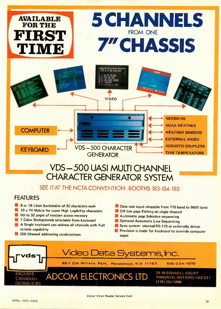
VDS -500 UASI MULTI CHANNELCHARACTER GENERATOR SYSTEM
SEE ITAT THE NCTA CONVENTION BOOTHS 183-184-185
FEATURES
8 or 16 Lines Switchable of 32 characters each 10 x 14 Matrix for super High Legibility characters Up to 32 pages of random access memory 7 Color Backgrounds selectable from keyboardII A Single keyboard can address all channels with Full
remote capability 256 Channel addressing combinations
111 Data rate input strapable from 110 band to 9600 band Off line page Editing on single channel Automatic page Selective sequencing Optional Automatic Line Sequencing Sync system: internal RS -170 or externally driven Provision is made for Keyboard to override computer
input
Video Data Systems, Inc.657 Old Willets Path, Hauppauge, N.Y. 11787, 516-234-1010
EXCLUSIVE
CANADIAN ADCOM ELECTRONICS LTDDISTRIBUTORS
29-16 CONNELL COURTTORONTO, ONTARIO M8Z 5T7(416) 252 5066
Circle 119 on Reader Service Card
APRIL, 1975-BM/E 25

Picture a newhigh performance,
One picture couldn't begin to tellthe whole story of how our newTR-600 compares with other "new"VTR's.
Nor would a hundred.But, we felt that a number of dif-
ferent views would give you a goodidea of what we meanwhen we say totally newtape technology.
Like the drop -on reels forinstance.
Then there's our unique straightline threading. It not only speedsloading, but once the tape reachesthe take-up reel, the operator is alsoassured that threadinghas been accom-plished properly.
The TR-600 utilizes a standardheadwheel (featuring long -lifeAlfecon II poletip material) that'scompatible with all other RCAhighband recorders. You'll find thisreally keepsdown theexpense ofspares.
26 APRIL 1975-BM/E

tape technology,medium price.
We've added an electronic LEDreadout tape timer. And LEDdiagnostic indicators.
At the firstsign of certainmalfunctionsor nonstandardmodes, a control panel light flashesa warning, while individual lights
inside direct you to themodule that's in question.
.79M13,".
_WOW_1:2211115-J0
We've simplified the control panelfor easy operation.
These module cards have thereliability advantages of computerassembly printedcircuit wiring and j.i#7sV:::;",'automatic insertion: .10of components. '11
Another TR-600 innovation isthe copperbackplanewhich as-sures pre-cise restingof modules.The backplane is wire wrappedunder computer control replacingthe past practice of using dense,bulky internal wiring harnesses.
Chimney coolingeliminates the needfor blowers anda Venturi vacuumsystem replacesnormally noisyvacuum pumps.
And for optimumplayback per-formance our tapetension servo systemfeatures fast rewindand is gentle in han-ding of tape.
Unfortunately, there are so many things we can't show you. Like allthe TR-600's automatics. Because they're all built in. Like the splicer,too. Or the fact that its new integrated design reduces the numberof components by 40%.
Nor can we show you the time and money the TR-600 will save you.But, if what we've shown you so far looks good, we'd be glad to
send you a more complete picture of the TR-600.Write RCA Broadcast Systems, Bldg. 2-5, Camden, RanN.J. 08102. Get the picture, then compare.
APRIL 1975-BM/E 27

Film Is Still In ThereAfter all the stirring -up portable video camera VTR combos havebeen doing lately, we need a look at film in television if we want acomplete picture. Film keeps on doing the things it does especiallywell.
Film, long the basic production medium for much oftelevision's recorded programming, has been yieldinglarge areas to videotape lately. But no one should get theidea that we are anywhere near a good -by* to film intelevision. The qualities that built film into our creative
A cinematographer can be a one-man crew with moderncameras.
Film camera presents no problem in going almost anywhere.
imagination for so long and made it highly efficient inmany important applications, are still at work, keepingfilm on the job in many television stations.
That fact emerged in a sampling survey BM/E madeof production houses that use both film and tape, televi-sion stations and film producers. One of the useful pointsmade several times was that the ultra -portable news -gathering video cameras which are sweeping the industry(BM/E, January) do not have, nor claim to have, thequalities for documentary or dramatic productions thatneed extremely well -controlled picture shading, lighting,color balance, etc.
If the highest "studio" quality is wanted, the producerneeds studio -quality cameras connected to quad VTR'sor high quality motion picture camera. If the programrequires a large number of "location" shots this meansthe video cameras and quad equipment would have to bemobile, requiring an investment much too large for manysmall and medium-sized stations.
The producer can do this kind of a job at a fraction ofthe cost, and with far greater mobility, with motion pic-ture cameras. That is just what several producers BM/Espoke to were doing. For example, Donald D. Gerdts,director of operation and production for KOCE-TV,non-profit community district station in HuntingtonBeach, California, told how the station produced adultteaching films that included location shots in many partsof the world.
In recent years more than 1500 people have signed upeach year for the televised adult education courses of-fered by KOCE. One of the most popular has been "Di-mensions in Culture," a three -unit course in culturalanthropology. For the course the KOCE camera crewwent to Egypt, Europe, Asia, South Africa, shootingmore than 100,000 feet of color film. This was editedtogether with videotape material into the 30 -half-hourprograms, each aired twice weekly.
Mr. Gerdts points out that the cost of doing the foreignshots on videotape, at the quality level the stationwanted, would have been far beyond the resources of thestation.
"There are certain kinds of picture quality you can getreadily with tape," Mr. Gerdts said. "We have trainedour cameramen to work carefully for the full exploitationof the strengths of the film medium. We are getting theresults we want and will continue to get them this way."
*The other day we got a call from a book editor asking for a photo of an"electronic news camera" reporting instant news "from some remotepart of the world." We said we had photos of TV cameras on citystreets in St. Louis but live coverage in unusual places was generallyonly possible if some prearrangements had been made to link up with amicrowave system or satellite. Our caller settled for a photo of a filmcamera shooting in the Everglades.
28 APRIL, 1975-BM/E

Our customers get resultsfrom the1440 AutomaticVideo Corrector.
FRCM WM. VANDERMAY,CHIEF ENGINEERKATU CHANNEL 2, PORTLAND, OR.
"The most remarkable device for videocontrol to appear on the market on the lastdecade is, without challenge, the Tek-tronix 1440 Automatic Video Corrector."
"Together with all of its bonus featuresthis instrument is a must for every trans-mitter installation."
FRCM RCA BROADCAST NEWSOCTOBER, 1974.T. M. GLUYAS, STAFF ENGINEER
"We have found that a most convenientway to automate modulation levels andsignal parameters is to use a Tektronixmodel 1440 Automatic Video Corrector ina closed loop mode around a transmitter,such as an RCA TT-30FL or TT -50H."
FROM JOHN KEAN, VICE PRESIDENTCONNECTICUT EDUCATIONALTELEVISION CORP.
"The 1440 has revolutionized our trans-mitter operation.... No trade-offs in signalquality are involved.""The visual RF drive control becomes theonly on -shift operating control.""To be able to adjust power with noapparent sync or video level changes issomething I am not used to yet.""Our Hartford transmitting operation hasbecome precise and nearly automatic.The power output stability exceeds FCCstandards by a factor of ten to one. TheVIR operated signal corrector is the majorreason for this."
FROM JOHN HITT, CHIEF ENGINEERKSLA-TV, SHREVEPORT, LA.
"Our transmitter is about nineteen yearsold. The Tektronix 1440 automatic colorcorrector has stabilized our output signalto a degree never before attainable.""The one most noticeable improvement isthe maintenance of proper sync -videoratio during line voltage variations.""With the 1440 in use the transmitterexcitation control can be adjusted to varythe transmitter output power from fifty toone hundred percent with the sync -videoratio remaining correct.""Our transmitter has some differentialphase, but having the 1440 match burstto VIR phase results in a very acceptablepicture. In fact, an AB test between trans-mitter output and microwave receiver out-put does not indicate any difference in thetwo pictures."
"When the show on VTR is a network playback, the VIR will control the six param-eters available. The most impressive thinghere is that the VTR operator can vary thecolor phase control on the VTR with nonoticeable change of color phase beingobserved on the air picture.""Our 1440 has been in service severalmonths and is doing a beautiful job. Weseldom have to make an adjustment in ournineteen year old transmitter."
FROM ROBERT F. SCHLIEMAN,ENGINEERING MANAGERWMHT-TV, SCHENECTADY, N. Y.
"I just wanted to let you know how pleasedwe are wits the 1440 Automatic Video
Circle 121 on Reader Service CardFor demonstration Circle 122
Corrector. This unit will be the key toallowing us to have automatic power con-trol of our UHF transmitter. As we auto-matically control the 110 KW output witha computer control system, the 1440 willmaintain the correct percentage of modu-lation."
Tektronix customers have provedthat the 1440 Automatic Video Cor-rector takes the work and the worryout of video signal quality control ...with FULLY AUTOMATIC CORREC-TION of overall video gain, blacklevel, color saturation, burst phaseand gain, and sync level.Call your Tektronix Television FieldEngineer for a special packet of in-formation about automatic video cor-rection. He can demonstrate how the1440 and other correction productswill work for you at incoming net-work feed, remote feeds, masterswitcher output, transmitter input andat other key points.
TEKTRONIX, INC.Box 500-A, Beaverton, Oregon 97077
TEKTRONIXcommitted to
technical excellence

KOCE-TV demonstrates value of film camera in shooting part of cultural anthropology series in Africa.
Editing Mm is easy. Here cinematographer takes close look at some of the footage exposed in Africa trip.
New color film for news introducedA new color film aimed directly at television news cov-
erage was announced late in January by Eastman KodakCompany. Called "7240 (tungsten)," the new Ektachromefilm gives television news departments a flexibility inchoice of exposure index ratings. With 10 foot-candles ofillumination, the film provides normal density ratings withtypical camera equipment, with quality, Eastman says,fully equal to that of Kodak Ektachrome EF 7242(tungsten). When shot at higher ratings and force proc-essed, it has significantly improved grain character ascompared with the 7242 Ektachrome.
The film is also pre -hardened in manufacture, elimi-nating the need for prehardener and neutralizer steps inprocessing; the process for the film, called VNF-1, is com-patible with current machinery and is faster and is lesscostly than current processes, because of the eliminationof the two steps.
The film is now on trade trial and will be marketed gen-erally about mid -year.
APRIL, 1975-BM/E

9 REASONS WHYYOUR PRESENT LENSES
JUST BECAME OBSOLETE.The remarkable new Fujinon lenses with
EBC are revolutionizing the television indus-try, and here's why:1. Glass -Any lens can only be as good asthe glass it's made from. So, to assure ourselvesthat we get absolutely the finest quality glass,we make our own. Traditionally, glass man-ufacturers use clay crucibles for the meltingof their raw materials. However, at the ex-tremely high temperatures required, reactionstake place between the clay and the moltenglass resulting in minute optical impurities inthe finished glass. At Fujinon we use expen-sive platinum crucibles, thus eliminating allpossible reactions between glass and clay.2. Computers -The designing of sophisti-cated lenses involves calculations that wouldtake an expert mathematician years to com-plete. Therefore, at Fujinon, one of the mostmodern computer installations in the worldconstantly works to maintain the superbquality of our lenses.3. Electron Beam Coating - Fujinon'sunique and exclusive coating process is themost advanced in the world, and it holdsseveral advantages over conventional coatingsystems: One is that thinner and more uniformcoatings can be applied. Another is that thereis a greater range of substances that can beused for coating. Thirdly, a greater number ofcoatings can be applied to a surface.LensSur-face
(k)
Transm ttance (%)
UncoatedT=(0951.
SingleLayerT---.(0 98)'
TripleLayerTr(0 995)'
EBCTr -(09981'
2 90 96 99 99 64 81 92 98 99 26 73 88 97 98 810 59 81 95 98 020 35 66 90 96 030 21 55 86 94 140 13 45 81 92 350 8 36 78 90 460 5 30 74 88 6
Fujinon lenses with Electron Beam Coating(EBC) can have up to 11 separate coatings;and it is these coatings that make ourlenses the almost perfect transmitters of light.4. Optical Transfer Function-The excep-tional performance resulting from the ElectronBeam Coating of Fujinon lenses can bemeasured in several different areas. The opticaltransfer function is a measure of total lensperformance; resolution, sharpness plusvarious kinds of aberration and contrast.By this critical criterion the Fujinon lenses
clearly deliver superior optical performance.5. Flare Factor -This is stated as the per-centage of the light reflected by the lens' sur-faces, the inside of the lens' barrel and the in-ternal mechanism.
5
4
3
2
0
FLARE FACTOR(Flare/f-number Curve)
Lens A
EBC Fujinon BCTV Lens
1.6 2 2.8 4 5.6 8 11 16f-number
Here again Fujinon lenses have lower flarefigures than comparable conventional lenses.6. Spectral Transmission - Color definitionis determined by the degree to which a lenstransmits the various wavelengths in the lightspectrum. Fujinon's use of rare earth elementsin making their optical glass; plus their ex-clusive Electron Beam Coating make theirlenses the ultimate in color transmission.7. Fringe Transmission -One commondrawback to many zoom lenses is inferiorfringe transmission, especially in their extremewideangle position. Not so with Fujinonlenses and their Electron Beam Coating. Theselenses enjoy outstanding fringe transmission.8.'72 Winter Olympics -The exceptionallyfine picture quality transmitted from Sapporo,Japan during the '72 Winter Olympics wasacclaimed by both the public and commercialbroadcasting companies the world over.Fujinon zoom lenses were utilized throughoutby NHK (Japan Broadcasting Corporation),which originated the coverage of the Games.9. First Time Available in the U.S.A.-Upuntil now you may not have been very familiarwith Fujinon broadcast lenses, but there's avery simple reason why: This marks the firsttime they'll be available in the United States.So if you want to get the jump on your com-petition by a marked improvement in thequality of your picture transmission, then yournext lens has got to be a Fujinon.
For information on the complete Fujinonoptical systems, contact Fujinon in New York.
Fujinon Optical, Inc., 420 West End AvenueNew York, N.Y. 10024 Phone: (212) 724-9834
APRIL, 1975-BM/E
Circle 123 on Reader Service Card
31

FILM
Jack Moss, head of Moss Communications, NewYork producers of documentaries, TV commercials, andother material on both film and tape, emphasized similarideas. He said that the producer of recorded visual pro-grams today needs a good grasp of the technical capacityand comparative cost, for a wide range of uses, of bothfilm and tape. He must decide with each job and eveneach part of the job which medium will do better, what iswanted, at the lower cost.
Even in the news gathering area, where the new video-tape systems are making such spectacular inroads, film isstill used far more than tape. This may not continue to betrue over some long period of time, but the changeover,
if that is what we will see, will take several years at theleast.
In the meantime, film is doing a splendid job at manystations; and we can be sure that the technology of thefilm and the cameras will not stand completely stilleither.
These viewpoints and others concerned with film innews are well expressed in the following excerpts byEdmund DiGiulio, president of Cinema Products Corp.,in an address at the winter meeting of the Society ofMotion Picture and Television Engineers, held at SanFrancisco in January. Di Giulio had the unenviable jobof being the only film man to appear at the session whichdescribed how ENG was being used at KPIX, WLACand the CBS network. Session moderator was Joseph A.Flaherty of CBS Television Network.
Today's 16mm CamerasAre Designed For Television News Gathering
First of all, I want to say that I resent appearing to be"the man in the high button shoes," fighting the lastditch defense for newsfilm. My company has been inexistence for seven years, the date I left Mitchell Cameraand started Cinema Products. And we were primarily in35mm equipment until we did make our entry in 16mmTV-newsfilm. In those short seven years, we havebecome the largest camera manufacturer in the UnitedStates.
When TV news exploded suddenly in the early 50's,equipment manufacturers were pretty well caught un-awares. The TV news people were desperately lookingfor equipment. It seemed that the little Auricon CineVoice 100 ft. camera had a good number of features thatmade it suitable. It was a silent camera, it was simpleand reliable. But it didn't completely fill the bill. So anumber of enterprising rental equipment companiesmade conversions of it, to add Mitchell magazines, andadd power supplies and such. F&B/CECO, GeneralCamera, Gordon Yoder, and a number of others, did an
CP-16R Reflex shown in use during the recent filming at Paramount Studioof "Sandburg's Lincoln." Six one -hour episodes of this network TI/ specialwere produced by David L Wolper Productions. Producer/Director isGeorge Schaefer; Director of Photography is Howard Schwartz.
excellent job of doing this. And these conversions basi-cally were the thing that we suffered with for the betterpart of twenty years. And I don't think that was verygood performance on the technical side in serving such avital and growing industry.
We introduced the CP-16 at the SMPTE Conference inNovember of 1971 in Montreal. We took a systems ap-proach. I was glad to hear Mr. Flaherty relate to a totalsystems concept. I think it's the only way one can con-sider these things. I think they did an admirable job atKMOX. We looked at the total system and consideredwhat had been done. We recognized that the Auriconmovement was a good, simple, rugged and reliablemovement, the recording heads and such had become astandard in the industry, so we unabashedly copied thesefeatures. However, the rest of the camera became a to-tally new system. We pioneered the development of acrystal controlled DC drive which was exceedinglyefficient. As you well know, synchronous motors run-ning from AC inverters consume a heck of a lot ofpower, and weigh a hell of a lot too. So with this drive,we could incorporate a very small plug-in rechargeableNicad battery. This gave us a very compact, lightweight,self-contained system. We then, over a period of time,added system elements to the basic camera. Wepioneered the development of a built-in Crystasoundamplifier with AGC and automatic switching betweenlive and record modes for operator monitoring. And thisthen became the "one -man -band" that was mentionedearlier. Subsequent to that, we introduced the reflex ver-sion of the CP-16 and this camera was well received.
We note at this time that our sales are running approx-imately three to one in favor of the reflex over the non -reflex camera. The appeal is that the reflex camera pro-vides a great deal more flexibility in the selection oflenses. You can use wide angle fixed focal length lenses,super fast lenses, as well as any number of zooms. Also,the full ground glass bright viewing enables the camera-man to compose and develop his shots as he goes along.We have continued to add system components. We in-troduced recently a wireless radio receiver that was de-veloped in close cooperation with Vega Electronics.
Mr. Flaherty gave us a good detailed presentation ofcontinued on page 34
32 APRIL, 1975-BM/E

Call me today-TOLL FREE
I'll arrange a Ditch Witch Demonstration on your job site.What's really the key to deciding what underground equipment to buy?
Ditch Witch believes it is per'ormarce: the ability to do the work youneed done, efficiently and econom cally. That's why your Ditch Witchman makes a standing oler to demonstrate Ditch Witch on yourjob site. Whether your underground recuirements are large orsmall, there s a Ditch Wi:ch that's exactly right: trenchers, vibra-tory plows, Modularmatics with broad job capabilities. LetDitch Witch prove what it can do. Call today and arrangefor a demonstration, when and where you want it. Look atDitch Witch capabilities: compare them with what the compe-
tition has to offer. Then decide which equipment can do thejob best for you. When you've considered everything, we
believe you'll understand why we say . . .
Today, More Than Ever,Ditch Witch Makes $ense.
CALL (8001 654-6481 TOLL FREE!Ditch Witch . . . equipment tram 7- to 195 -HP.
CHARLES MACHINE WORKS, INC.P. 0. Box 66
Perry, Oklahoma 73077
Circle 124 on Reader Service CardAPRIL, 1975-BM/E 33

". . . to bring itup and hangit there."
That's what one Chief Engineer said abouthis modulation and talk power when describing,why he installed the SPOTMASTE R®SoundBritener.
He had a typical problem - periods of lowmodulation due to several programming sourcesincluding live telephone reporting. His originalsolution was the costly, slow and inaccuratemethod of watching a meter and continuouslyadjusting the level. He then tried the commontwo unit compression/limiting system - oneunit at each end of the lines to his remote 50kW transmitter. He still had problems - andmany, many adjustments to fool with.
Now he has the SPOTMASTE Re C LE -500Sound Britener. It has only three adjustments- all behind the front panel - and it's opera-ting unattended at the studio. A single metershows at a glance what it's doing. His averagecommon point current at the transmitter isup - and hanging right there - with full pro-tection against over modulation. His talk pow-er and fringe area coverage are increased. Andit's all automatic with the Sound Britener.
Why not try it yourself on our 30 day freetrial?
BROADCAST ELECTRONICS, INC.I mom = A FILMWAYS COMPANY
8810 BROOKVILLE ROADSILVER SPRING, MARYLAND 20910PHONE: 301-588-4983
FILM continued from page 32
the KMOX operation. And he presented some cost data.And of course I can't question the validity of his data. Iwas a bit surprised, though to see that the capital equip-ment cost was so nearly the same for film and videotape,when I know that the comparable video camera and itsrecorder cost about 8-10 times what our film cameradoes. I was also rather amused to see the announcementin the trade press in which they describe the total con-version cost to go to electronic news gathering atKMOX. They indicated that the total investment wasapproximately $400,000. Projections of saving on film,film processing, and additional technicians needed forthe old system show that the network should make itsmoney back within seven years. Now I ask you, gentle-men, how many of you would invest $400,000 with theexpectation that you will break even in seven years? Ithink if it were an apartment building, I might be in-clined since I don't expect the technology of apartmentbuildings to move too far forward in seven years. But Idon't know that any one of us would dare say the samefor electronic news gathering.
There's another wry observation I would make: whilethere was a and film processing, there was none what-soever for videotape . . . am I to understand that all theTV news directors are going to immediately erase thevideotape the morning after they've recorded it? I knowI've tried scrounging around Hollywood with Stan Zieveand others to get film short ends or out -takes so I couldpractice in my cameras. And I was always told that theirlegal departments would not allow any piece of filmwhich is a valuable archival record to leave their prem-ises. So I guess we're going to change the ground rulesas far as electronic news gathering is concerned, other-wise those numbers won't come out.
I also liked the way that newsman came right out ofthe van, fully loaded down with all of the stuff hangingfrom him! A film cameraman with a CP-16 one -man -band operation on his shoulder is taking film the minutehis foot hits the sidewalk outside the car.
I think that developments and progress will be made infilm. Eastman Kodak has never been known to be ashrinking violet, and Cinema Products isn't either.We're going to develop new hardware, we're going todevelop new techniques, and we're not going to go"smilingly into the sunset." We're going to enjoy thecompetition. We're going to welcome what's done elec-tronically.
I could frankly make a number of other comments. AsI said, I could make invidious comparisons of the advan-tages of film over tape. But I think that the more im-portant thing to consider is that it is a total system con-cept. There were some brief mentions of the fact thatthere are other considerations. I would say that some ofthe labor and union considerations have not been talkedabout. And perhaps this is not the proper forum, but letus not forget them. Let's consider the total system in anews gathering operation. Let us consider what the ap-propriate role of film is and the appropriate role of video-tape. BM/E
Vote For The Best Great IdeaSee Page 50
Circle 125 on Reader Service Card
34 APRIL, 1975-BM/E

Transmitter Remote Control --A Status ReportBy John E. Leonard, Jr.
The basic concepts of remote control and some systems currentlyavailable are described here for both managers and engineers. Inthe accompanying material, how remote control is used at WWLAM -FM -TV, New Orleans, and WFUN, Miami, is covered.
When we talk about remote control in our industry weusually mean the unattended operation of the broadcasttransmitter and its associated physical plant-antennas,tower lights, etc. Transmitter remote control was firstauthorized by the Federal Communications Commissionin 1953. At that time, operation was limited to non-directional standard broadcast (AM) stations with powerlevels .through 10kW. More recently, the FCC Ruleswere altered to allow all television stations to remotecontrol their transmitters. Today any broadcaster whosetransmitter is located away from the studio may decide toemploy remote control equipment. The intent of this ar-ticle is to familiarize both managers and engineers withthe basic concepts of remote control and some of thesystems currently available. No effort will be made torelate these concepts to specific operational or technicalrequirements. (Editor's note: see separate article onWFUN and WWL-AM-FM-TV.)
In the past 22 years, the technology of transmitterremote control has advanced greatly. In this time, remotecontrol systems have evolved from basic passive -relay -switch systems to computer -aided systems. Thesechanges have resulted in designs that enable better con-trol and observation of the transmitter than is possible byan operator actually at the transmitter site. Im-provements in technology allow, for example, extremelyaccurate metering of power and other operating parame-ters.
Before exploring the hardware aspects of remote con-trol, a review of "what is remote control" seems inorder. Information flows in both directions between thestudio or remote control point and the transmitter site.These are typically identified as control or commandsand metering or telemetry. Commands are fed from theremote control point (usually the studio) to the trans-mitter site. Metering functions are returned from thetransmitter to studio. A channel -type approach is used bymanual remote control systems. Normally, a channelprovides the capability of issuing two command func-tions and observing one metering function. This con-figuration is unique to broadcast transmitter needswhere, as an example, plate voltage can be increased ordecreased while observing the actual plate voltage. Thetwo command functions are referred to as "Raise" and"Lower." Other commonly used terminology for com-mand functions is "On/Off' and "Start/Stop," or thelike. Most commercially availabe remote control
Mr. Leonard, Jr., is marketing manager for MoseleyAssociates, Inc., Goleta, Calif.
systems provide dry contact closures as outputs at thetransmitter site for universal interface to the transmitterand other equipment. For metering purposes, a low po-tential DC voltage is developed to represent the actualparameter. This DC voltage, called a "sample," is di-rectly proportional and must track any changes of thedesired parameter. Recent practices are toward makingboth the sampling and control functions floating and iso-lated from ground and other parameters. Further in-formation is given below on the functions possible withremote control equipment.
The first decision-telephone or RF interconnectIn considering remote control, normally the first de-
cision is the method or interconnection circuit to be usedfor relaying information between the studio and thetransmitter site. This decision can affect the equipmentto be utilized for remote control. Typically, two differentmodes of interconnect facilities are available-leasedtelephone circuits or independent (station owned) radiointerconnect. Several block diagrams are included to ex-emplify these different modes. Selection of one inter-connect facility over the other is normally based upon theactual operating costs as well as reliability. A number ofstations utilize both interconnect circuits in an effort toprovide redundancy to obtain a higher reliability factor.
Many functions can be controlled or monitoredThe actual functions to be controlled and monitored
have changed drastically since the beginning of remotecontrol. Early systems were typified by performing ofonly basic functions. Many present-day systems are de-signed to allow observation of even the most minutetransmitter plant and environmental parameters. Theactual functions should, of course, be determined bystation engineering and operating personnel who are in-timately familiar with the plant's operation. The per-sonnel operating the transmitter plant know the abso-lutely necessary functions, the desirable functions, andthose that need not be observed. In selecting the func-tions, care must be taken to insure compliance with cur-rent Rules and Regulations. Fig. 4 shows some of thetypical functions.
After establishing functions of interest, selection ofremote control equipment selection then becomes some-what simpler. Functions typically are divided into threebasic categories-command, telemetry and status.Command functions are simply those controls which canbe accomplished from the studio. Among these would befilament on/off, plate on/off, power raise/lower, etc.
APRIL, 1975-BM/E 35

TRANSMITTER REMOTE CONTROL
Telemetry functions are simply the meter readings to beobserved. Included here are not only transmitter parame-ters such as plate voltage and plate current, but also anyother parameter which can be expressed in an analogmanner, such as AC line voltage, tower light current,building environment, etc. Status indications typicallyfall into the category of optional items. These are go/no-go type indications. Among these are illegal entry,transmitter fault lamps, smoke sensors, and the like. Inthe selection of remote control equipment, the overallcapacity should be considered in light of possible futureexpansion. Likewise, the ease with which functions maybe rearranged or modified should be considered if long-range plans are being formulated.
Types of equipment availableThe equipment available for transmitter remote con-
trol varies from a simplified analog system to verysophisticated computer -assisted digital systems which
STUDIO TRANSMITTER SITE
REMOTE CONTROL I
STUDIO UNIT 0
COMMAND
TWO-WAY TELEPHONE e REMOTE CONTROLCIRCUIT p TRANSMITTER
e UNITTELEMETRY
CONTROL
V
AM,FM, OR TVTRANSMITTER
TER NG
Fig. 1 Block diagram of telephone line remote controlsystem. Only a single telephone circuit is requiredbetween studio and transmitter site.
STUDIO
AURAL PGMSOUND CHANNEL
GENERATOR
VIDEO PGM
SOUND CHANNEL
GENERATOR
1
V
VIDEO
STL TRANSMITTER
6.8 MHz
COMMAND
111REMOTE CONTROL
STUDIO UNIT
METERING
4TELEMETRY
RECEIVER
STUDIO
MAIN PROGRAM INPUT
AURAL STL
TRANSMITTER
could take complete control of a transmitter plant. Theearliest analog remote control systems were those utiliz-ing simple DC techniques. With these systems, the DCcontinuity of the telephone circuit was utilized to conveyvoltages for directly activating relays for control func-tions. A second DC circuit was utilized for return of theDC sample voltages. Fig. 5 is a photograph of one ofthese systems.
In the evolution of remote control, the next step was toa system using a single DC telephone circuit. Both theAC and DC properties were used for these systems. Con-trol was accomplished by audio tones impressed on thetelephone line. The DC continuity of the circuit providedfor metering. In many parts of the country, telephonecircuits having DC continuity have become unavailable.For this reason, analog systems were converted to typesutilizing only audio tones for relaying the desired in-formation. A simplified block diagram of a system utiliz-ing audio tones is shown in Fig. 6. This system uses aform of pulse duration modulation for relaying commandinformation. The audio tone that actually appears on thetelephone circuit for relaying command information is
FM CONTROLSUEICARRIER
REMOTE CONTROLSTUDIO UNIT
METERINGSIGNALS20-30 Hz
FM
TELEMETRY
RECEIVER
950 MHz WITH26104 SUB
100 MHz WITH67 KHz SCA
MAINPROGRAM
(AUDIO)
TRANSMITTER SITE
FM CONTROLSUBCARRIER
METERINGSIGNALS
20-30 Hz
67104 SCASUEICARRIER
Fig. 2 Block diagram of typical wireless remote control system for FM transmitteroperation. Requiring the use of an aural studio -transmitter link (STL). Commandinformation is relayed to the transmitter site by an FM subcarrier multiplexed onthe STL. Currently produced remote control equipment contains provisions forinternal subcarrier generator and detector. Metering information is returned viathe SCA channel.
FOR 12 GHF
TV SIGNAL(AURAL WITH 39104 SUBCARRIER )
I
VIDEO
STL RECEIVER6.8MHz
TRANSMITTER SITE
T.3 MH
SOUND CHANNEL
DEMODULATOR
SOUND CHANNEL
DEMODULATOR
COMMAND
grVIDEO PGA,
REMOTE CONTROL METERINGFM
SURCARRIERXMTR UNIT
GENERATOR
CONTROL
V
TV TRANSMITTER
METERING
AURAL PGM
I AURAL
EXCITER
39
4-4
Fig. 3 Block diagram of typical wireless TV remote control configuration is quite similar to the FMsystem. A sound channel in the video STL relays command information to the transmitter site. An FMsubcarrier is multiplexed on the aural carrier for metering return.
36 APRIL, 1975-BM/E

actually shifted in frequency to transmit the desired in-formation. Telemetry is returned via an FM scheme. Inthis case, a stable and linear voltage -controlled oscillatorin the system has its frequency controlled by the samplevoltage. Only a single audio tone appears on the tele-phone circuit for metering. The frequency of this tonedetermines the meter deflection at the studio. Carefulselection of the audio frequencies for command and me-tering at the time of system design enable operation overa single telephone line. As an example, the systemshown in Fig. 6 uses audio frequencies in the 300 Hz to400 Hz spectrum for command. Metering occupies the800 Hz to 1200 Hz spectrum. These tones fall within thenormal range of speech and allow for use of inexpensivetelephone circuits. Systems of this type have been usedsuccessfully over standard dial type circuits coveringover 3000 statute miles. Of course, tones of this type areeasily relayed by radio circuits.
Digital transmitter remote control systems are avail-able in a number of sizes and configurations. Thesesystems perform basically the same tasks as the analogsystem just mentioned. However, digital techniques areutilized which result in improved overall reliability.Among the advantages of the digital system is display ofactual parameters numerically. This simplifies therecording of parameters by unskilled operators. Like-wise, tally -back measures are typically included toverify the accomplishment of command functions.Larger system capacities for command, telemetry andstatus are extremely easy with a digital system. Ex-pansion after instillation is quite simple with severalcurrently available systems. Likewise, the number oftransmitter plants controllable with one system is in-creased with digital systems. The integrity of the in-formation transmitted between the studio and transmitteris also much higher utilizing digital techniques. Parity,framing, and similar coding schemes are used for trans-mission integrity. This assures activation of the propercommand functions without the issuance of false com-mands or the receipt of false metering parameters. Theseare but a few of the attributes associated with digitalsystems.
Role of the computerThe advent of digital systems brought with it the use
of computers. Generally, two types of computer systemsexist -the computer -based system and the computer -as-sisted system. For the braodcasting industry, the com-puter -assisted approach for transmitter remote control isthe most commonly used. Digital systems are currentlybeing employed mainly in television stations. A basicdigital remote control system providing command, tele-metry and status functions is established. A computer isthen utilized to assist overall operation. Visual display ofmany channels simultaneously with a cathode-ray tube(CRT) display is possible. Likewise, tolerance checkingof each parameter against upper and lower limits caneasily be accomplished. In some installations, doublelimits are established to provide early warning of a pend-ing problem. The computer -assisted system also enablesvarious forms of automatic parameter logging. Variousprinting devices allow recording of only required param-eters or, if desired, every parameter appearing on thesystem. As mentioned previously, with the addition of acomputer, totally automated operation is then feasible.Such computer operation has been made economically
Typical Remote Control, Metering,Control and Status FunctionsControl Functions:
1. Transmitter Start (Filaments, Blowers and PumpsON)
2. Transmitter Stop (Filaments, Blowers and PumpsOFF)
3. High Voltage On (TV includes Aural/Visual)4. High Voltage Off (TV includes Aural/Visual)5. Power Raise (TV includes Aural/Visual)6. Power Lower (TV includes Aural/Visual)7. Normal Power Operation8. Low Power Operation9. Driver On (Typically TV only)
10. Driver Off (Typically TV only)11. STL Changeover to Auxiliary Receiver12. Transfer Switch Activate (to change to auxiliary an-
tenna or transmitter)13. Auxiliary Generator Start/Stop14. Auxiliary Equipment On/Off (Heaters, Air Conditioner
or Tower Lights)
Metering Functions:1. Filament Voltage2. Plate Voltage (TV includes Aural/Visual)3. Plate Current (TV includes Aural/Visual)4. Power (TV includes Aural/Visual)5. Driver Power (Typically 1V only Aural/Visual)6. Phase Angle/Loop Current (AM Directional)7. Common Point (AM Directional)8. Tower Lights9. Line Voltage (Single/Three Phase)
10. Room Temperature11. Exhaust Air Temperature (From Air Ducts)12. Reject Load (TV only)Status Functions:
1. Building Security2. Fire Alarm3. Smoke Alarm4. Telemetry Fail -Safe (TV only)5. Auto Restart Override6. S.W.R. (AM/FM/TV)7. Driver Overload (For TV Visual/Aural)8. Amplifier Overload (For TV Visual/Aural)9. Air Flow (For TV Visual/Aural)
10. Water Flow (where applicable)11. Aux Generator On/Off12. Water Emerson Heaters (where applicable)13. Dummy Load Water On/Off
Fig. 4 List of remote control, metering and status functions.
Fig. 5 Typical dc telephone line system studio unit. Unit shown isGates RDC-1 OAC.
APRIL, 1975-BM/E 37

TRANSMITTER REMOTE CONTROL
ra
4HANNELSELECTOR
RAISE
LOWER -I
RECYCLE --I
STUDIO UNIT(CONTROL TERMINAL)
METERINGDEMODULATOR
CONTROLGENERATOR
OPTIONALTELEMETRYSUBCARRIER
DEMODULATOR
METERING METERINGINPUT OUTPUT
0
CONTROLSUBCARRIERGENERATOR
L.
RADIOL I NK
TELEPHONELINE
OPT IONALTELEMETRYSUBCARRIERGENERATOR
TRANSMITTER UNIT( REMOTE TERMINAL I
II,
CONTROL CONTROLOUTPUT INPUT CONTROL
RADIOLINO
SUBCARR I ERDEMODULATOR0
METER NGGENERATOR
CONTROLDEMODULATOR
,AGOITA AE
;CALIBRATE
0 R EL
1F13
RAISERELAY
c.409-
LOERRELAY
Fig. 6 Block diagram of a remote control system using only audio tones. Such a system can be usedwith either telephone fine or wireless interconnection facilities.
Fig. 7 Digital remotecontrol system studiounit. Unit shown isMoseley Model DCS-2Control Terminal.
Fig. 8 CRT displayused withcomputer -assistedremote control systemenables thesimultaneouspresentation of 30metering or statusfunctions. All commandfunctions are enteredthrough keyboard.
feasible with the advent of the minicomputer. Changes insoftware can then enable the control hardware to be re-programmed to comply with the changes in operation ofthe station.
Outside the United States, digital transmitter remotecontrol systems enable extremely efficient operation.Requirements by licensing agents allow stations morefreedom in their approach to remote control. As an ex-ample, Hong Kong Television Broadcasts Limited(HK-TVB) in Hong Kong utilizes a series of translatorsfor full coverage. A multi -site digital remote controlsystem is used to control all sites. This particular systemcan accommodate up to 16 different transmitter sites.
FAI LSAFE
0FAIL-SAFE
RELAY
METERINGSAMPLEIN PUT
'-°--43 RAISEOUT PUT
LOWER
));)OUTPUT
CHANNEL I
RELAY
CHANNELS 2-15NOT SHOWN
Using a minicomputer, this system enables observationof all sites, total logging of all parameters, and absolutecontrol of the entire RF broadcast system. As a side note,the system uses 450 MHz RF links for interconnection toall transmitter sites.
Automatic logging can be integral partAutomatic logging is also typically considered part of
the remote control equipment. With the relaxed trans-mitter logging requirements, many stations are re-eval-uating the use of this equipment. The outstanding pointto consider is that, even with relaxed requirements, aburden of proof still remains with the licensee to provethat the transmitter was operated within the specifiedlimits. Mechanized logging equipment, of course, pro-vides a permanent record free of operator error. It is forthis reason that many stations do install automatic log-ging equipment. Originally, hardware of this type con-sisted of a chart recording device. Early tests were con-ducted using both strip chart and circular chart ap-proaches. Current equipment utilizes printing devicessuch as teleprinters. These record parameters directly asa typewritten number.
Monitoring tomorrows automatic transmitterOn the horizon for remote control of broadcast trans-
mitters is the automated transmitter. With the anticipatedadvent of automated transmitters, which are not ap-proved at this writing, one of the most often asked ques-tions is what will be the role of remote control equip-ment. Because of large capital investments in a remotetransmitter site, most stations concur that, even with anautomated transmitter, it will be extremely desirable tomaintain a means of monitoring the transmitter as well asseizing manual control. It is anticipated that remote con-trol systems currently in existence would provide suchcapability. Until rules are developed for automatedtransmitters, this point must remain speculative. BM/E
38 A 0011 I 07C-Ok A IC

Remote Control of Radio Station WFUN*By V.C. Roberts, Chief Engineer
Rounsaville Radio Station WFUN, South Miami,Florida, achieved remote operation on 26 June 1974.While planning for remote operation had begun sometwo years previously and certain equipment such as anSTL with subcarrier possibility and a new remoteableantenna monitor were installed during this time, pur-chasing of major equipment was delayed pending finalFCC approval of license for remote operation. Approvalwas received 1 November 1973, at which time orderswere immediately placed for the remainder of the neces-sary equipment.
Studio and transmitter sites at WFUN are separated byseven miles, most of which is heavily trafficked citystreets. At the transmitter site there are two transmitters,main and alternate main, operating at 5 kW on 790 kHzinto a six tower array spread over 47 acres of Evergladesfringe. All six towers are used in Day Array while onlyfour are in use during Night Array. Power is constant inboth modes. In remote operation we are, therefore, pre-sented with the necessity of reading six loop currents andfive phases on day pattern and four loop currents withthree phases on night pattern together with other FCCreadings normally required.
In addition to an occasional hurricane, South Floridanormally has some 80 odd inches of rainfall per year.Statistically it is more susceptable to lightning stormsthan any other area on earth. Because of these con-ditions, interruptions to both telephone and commercialprimary power service frequently occur. Substitutes forfailed facilities are necessary. Much of such equipmenthad already been automated over the past 15 years toaccomodate fast recovery from casualty (and to allowdependable station operation with a single operator onduty at the transmitter.) WFUN operates 24 hours, sevendays a week. Motor -generator sets had been installed atboth studio and transmitter locations, which activate onfailure of commercial power. Pattern change from onecondition of antenna array to the other was a singlepushbutton operation. Switching between the two trans-mitters occurred automatically when the one on the airfailed for any reason. A stand-by program tape, activatedwhen no program was received at the transmitter fromthe studio for a thirty second period, was automaticallyfed into the transmitter at that location. A complete testof the EBS (including transmitter of-ons, tone, and voiceannouncements) was initiated by a single pushbutton atthe transmitter site.
Most of the foregoing was readily adaptable for inter-face with remote control equipment by using such stand-ard items as Moseley's Sampling and Reversible MotorKits PVK-1, MBB-1, TSK-3, RFK-1, and RMK-1. Anumber of special devices had to be fabricated on thespot to accomodate certain metering and control neces-sities peculiar to WFUN's requirements.
We felt that extensive metering and control of bothmanual and automated operations, occurring in an un-'Any account of this project would be grossly incomplete without the mention ofthose who are indeed as much a part of the accomplished project as is the writer.The wisdom and guidance of Paul B. Cram, Technical Director Emeritus ofRounsaville Radio and the ability and hard work of Michael D. Lee, who hassince become the Chief Engineer of Rounsaville Radio WMBR, Jacksonville,Florida, went into the project in generous portions from conception to comple-tion.
manned building seven miles away, was essential to de-pendable station operation. Automated facilities some-times require human help, in the form of judgement, asto manual start-up, abort after auto -start, etc. Whenstatic crashes are evident in the air monitor, when blacksquall lines are visible and moving in toward the trans-mitter site area, when the low sky is laced with lightning,then human judgement dictates manual start-up andtransfer of power source from commercial to auxiliarymotor -generator supplies. Such action anticipates tran-sients on commercial power lines and the sudden demiseof transistors. At such times it is advisable to monitor thestatus of voltage, oil pressure, water and oil temperatureof the motor -generator as well as fluctuations of thecommercial power source. We can head off catastro-phes.
Accordingly, WFUN installed two each MoseleyTRC-15A units with 26kHz and 67kHz subcarriergenerators which operate through the previously in-stalled Moseley PCL 404 STL System. This systemcarries our main program and control signals from bothTRC-15A Units from studio to transmitter. WhileMoseley equipment has the capability for metering usingsub -audible tones returned to the studio via WFUN'scarrier, we opted to use RT telephone circuits for themetering return path. The reasons for this decision were,1 we would not loose our metering path simply becauseof a failure which caused neither transmitter to come upon line, 2 we can by-pass the subcarrier generators in theTRC-15A Units (demodulators at transmitter end) andsend control function pulses to the transmitter via the RTcircuit while simultaneously receiving metering at thestudio on the same circuit. Program at such time can besent to the transmitter via 15Hz equalized telephone loopwhich is maintained as back-up for the STL. This allowsoperation if the PCL 404 System is down for any reason.Furthermore, metering can be done with telephone lineshaving low frequency response and/or high noise con-tent-and even with one side of the line at dead ground.Another factor, was the Program Department's absolutedistaste for any reduction in carrier modulation to ac-comodate subaudible tones on the carrier. While we mayin the future install the subaudible equipment for purposeof redundancy, operational experience to date has notjustified that action.
WFUN's Studio TRC-15A unit with 26kHz subcarrierwas factory modified during construction to add one setof dry contacts each to the "Raise" and "Lower" func-tion controls. The purpose of this modification was toallow operation of the relay on a Potomac InstrumentRMP-19 Remote Loop and Phase Meter Panel installedat the studio control point. The RMP-19 Panel dupli-cates, exactly, the metering in the Potomac InstrumentAM -19 Antenna Monitor, earlier installed at the trans-mitter. While making measurement of Loop Current andPhase, the meter of the TRC-15A is disconnected withthe output of the meter demodulator being channeled tothe RMP-19 for readout on the appropriate instrumentface. This action was greatly simplified for the operatorby the minor modification to the 26kHz TRC-15A. Atthe time WFUN was installing remote equipment,
APRIL, 1975-BM/ E 39

TRANSMITTER REMOTE CONTROL
Potomac Instruments did not have their RSA -19 Switch-ing Adapter in production. This device forms the inter-face between the AM -19 Antenna Monitor and theremote control equipment. Therefore it became neces-sary for us to construct a 12 relay switching device,essentially equivalent to the RSA -19.
The switcher was fabricated on a standard 19" rackpanel 10" wide using Potter -Brumfield plug-in relays andinstalled at the transmitter close to the AM -19 Monitor.One pair of relays is associated with each channel, 8through 13 of the TRC15A 26kHz Unit, with each ofthese channels representing one of our six towers; i.e.,Channel 8 reads Tower No. 1, Channel 9 reads TowerNo. 2, etc. One coil of each pair of relays is actuated bythe "Raise" function of the TRC-15A and the other coilof the pair by the "Lower" function of the respectivechannel. The total result is that at the studio we mayselect Channel 8 (Tower No. 1), whereon Loop Currentmay be read by depressing the "Raise" function andPhase may be read by depressing the "Lower" function.Channel 9 selects Tower No. 2 with the same operationbeing repeated in order until all 12 operating parametersfor the six towers have been read.
All FCC required readings and control functions forthe two transmitters as well as the six towers, are op-erable using only the 26kHz TRC-15A. In addition tometering the Common Point Current, Plate Voltage,Plate Current, Loop Ratios, and Phase, we can startand/or stop both transmitters, adjust plate voltage
WFUN Remote Control Panel at studio.From top down, Belar AMM-1 Monitor,Moseley 26 kHz TRC-15A Remote Con-trol upon which all required readings aretaken, Potomac Instrument RMP-19Loop Current and Phase Meters, 67 kHzTRC-15A unit for control and metering ofauxiliary transmitting equipment. Onbackside of the hinged panel at bottomof rack are terminal blocks for entire unit.
(adjusts power into the common point), change antennafeed from one transmitter to the other, change to eitherday or night array, activate the automated EBS deviceand/or automated program tape (previously described)and abort these two devices at any point in their cycle.Almost as a bonus we may also measure air temperaturein the final stage compartments and that in the exhaustduct above each of the transmitters.
It may be of interest that some of our metering is in thenature of multi -step logic. One instance is associatedwith antenna pattern change. A single channel of the26kHz TRC-15A with its "Raise" and "Lower" func-tions perform all of the following: The Antenna system aligns itself for Day Array whenthe Raise key is pressed. Then when all relays and con-tactors in Phasor and six Tower Houses have assumedcorrect position, the TRC-15A meter indicates % fullscale showing that the command has been properly ex-ecuted. This allows the transmitter to automaticallycome up to feed the antenna approximately one secondlater. (At this point a meter reading above the high end ofthe scale (10 plus) indicates that one or more of therelays or contactors did not align in Day Array posi-tion-which would, of course, prevent the transmitterfrom coming back on line.) Conversely, a reading ofZero on the meter indicates failure of only the meteringpower supply-which does not inhibit return of thetransmitter provided that all relays and contactors haveassumed correct position.) When the same channel is locked in for change toNight Array, the "Lower" key is depressed to effect thechange. Normal change to night pattern is indicated by a
Here disc jockey Bradford Baad operates RemoteControl Panel. The equipment sets atop a verysturdy metal typing stand. Casters on stand allowthe equipment to be easily moved. All lines to andfrom the control panel are formed into a long umbil-ical cord which permits moving from studio tostudio.
4
STL Antenna at studio atop a 70 -foottelephone pole is fed from the multi-plexed Moseley PCL-404 Transmitter(mounted in the Master Control Racks).The receiving antenna is mounted at the200 foot level on one of the six towers atthe transmitter site and feeds through anlsocoupler at the tower base into theAural STL Receiver. Colinear array,on pole, is two-way mobile.
40 APRIL, 1975-BM/E

meter reading of '/3 scale or 3. In this instance a readingof 6 indicates the array has remained in the day condition(no change occurred), Zero indicates failure of the meter-ing system, and 10 plus indicates one or more relays orcontactors is improperly aligned (split pattern). There are16 Johnson R.F. Contactors and 31 pilot, metering, andAC power relays- in the WFUN phasor, power divide,distribution, and antenna tuning system all of whichmust be properly aligned for pattern change to be com-pleted and the transmitter to be brought up on line.
During integration of this large system with interfacefor remote control, judicious application of a number ofZener Diodes and similar small solid state componentsproduced the multi -step logic states as described above.Similar circuitry has been used as refinement dictatedthroughout the WFUN installation.
The second TRC-15A Remote Unit (67kHz) is used tomonitor and control functions at the transmitter whichalthough not required per se by the FCC are none the lessessential to rapid location of trouble, either impending orafter the fact, smooth station operation, and generallyjust staying on the air which is undoubtedly the name ofthe game.
The following functions are controlled and/or meteredby the 67kHz TRC-15A:1. Analog indication of audio input at transmitter feed;2. control of transmitter power output allowing ob-servation of applicable metering at any channel of the26kHz Unit simultaneously;3. switch transmitter input to output of either the STL orthe Equalized Telco Loop and indicate which is feedingthe transmitter;4. change antenna feed to and energize either transmitterwhich was not on line at the time and indicate whichtransmitter is feeding the antenna (multi -state logic);5. analog indication of DC current being drawn frompower supply by metering relays;6. command a 180° phase shift of the antenna monitorand indicate each tower in succession to allow channelgain check and/or adjustment of Antenna Monitor;7. analog indication of STL microwave signal strengthat transmitter site;8. indication, in groups of three towers, the status oflighting including whether top beacons are flashing;9. indication whether transmitter building is drawingpower from commercial source or from auxiliarymotor -generator;10. command transmitter building to lock onto com-mercial primary power or to resume normal automatedoperation and indicated acknowledgement of eithercommand;11. command transmitter building to lock onto auxiliarymotor -generator supply or to resume normal automatedoperation and indicate acknowledgement of either com-mand;12. multi -step logic indication of status of commercialprimary power, i.e., not available, available but un-reliable during past thirty minutes, both available andreliable;13. analog indication of output voltage of motor -generator;14. indication if any flag is up on annunciator of au-xiliary motor -generator system (failure of oiling, cool-ing, etc. indicated);15. floodlight control for security perimeter of trans-mitter building with indication as to status on or off.
A portion of rack equipment at transmitter site.From top to bottom, lower edge of the 67 kHzTRC-15A Transmitter Remote Terminal, the 26 kHzTRC-15A Remote Terminal, the Aural STL Re-ceiver, Antenna Monitor Interface Panel, PotomacAM -19 six -tower Monitor. Open space above theantenna monitor will house interface for remote logprintout.
t4t%fitei4- .4 %. %Ai' yrei'Veniele.b
To left is rear view of interface panel to Potomac RSA -19. Unit"pushes buttons." Two relays are necessary for each tower. Toright is rear view of TRC-15A transmitter remote panel. Wiringharness perrnits terminal panels to hand downward.
Several channels are not presently in use but arescheduled for use with equipment which has not as yetbeen installed.
A Belar Model RFA-2AM RF Amplifier was installedat the studio which directly feeds a Belar Model AMM-1Frequency and Modulation Monitor moved in from thetransmitter building to the studio control point.
WFUN is scheduled to add automatic Operation Logprint out with tolerance alarm and including print out ofselected auxiliary metering (eleven items) in addition toall readings required by the FCC. This phase of theproject is believed to be approximately 75% completewith some of the equipment presently installed and in thetest stage. Continuing effort to explore, implement, andimprove the myriad possibilities of remote control andautomation is being made.
After round-the-clock operation seven days a week forthe past eight months, a conservative evaulation of theWFUN Remote Control System could be no less thanVERY SATISFACTORY IN ALL RESPECTS.
APRIL. 1975-BM/E 41

TRANSMITTER REMOTE CONTROL
Remote Control of WWL - AM - FM -TV Transmitters*The studios and offices of WWL-AM-FM-TV are lo-cated in the French Quarter of New Orleans. Two TVtransmitters (25 kW main and alternate), the FM trans-mitter (20 kW) and an auxiliary AM transmitter (1 kW)are on one site about 4.2 miles from the studio. The 50kW main clear -channel AM transmitter and a 10 kWalternate are at a second site. A move is currently under-way to relocate the second site to Marreno, about 8 milessouthwest of the studios. At that time the alternate AMwill also be increased to 50 kW and the 10 kW unit willbecome the auxiliary at site one. WWL has operated themain AM transmitter remotely via land lines from theFM/TV site since 1965. A staff of six were responsiblefor operating and maintaining all transmitters.
In 1973, WWL decided to remote control all trans-mitters from the studio in accordance with new FDCrules. It has been fully operational since July 1974. Theobjective was a system that would minimize on -site op-erational control and monitoring while maximizing reli-ability and performance. Now a staff of three do on -sitework including preventative maintenance and repair.The remaining three of the original crew have been trans-ferred to the studio.
WWL prizes reliability both from a professional andprofit point of view. In talking to chief engineer HughBurney, you get a strong impression that down time isthe worst thing that could befall him. The AM and FMoperate 24 hours a day. TV has a 20 hour day schedule; ithopes to go 24 hours. Because of the insistence on reli-ability, microwave links are used instead of land linesand there is complete redundancy in the remote controlsystem.
If using interconnecting microwave links, as WWLchose to do, control information requires a unidirectionaltransmitter/receiver path and a separate unidirectionaltransmitter/receiver path operating in the reverse direc-tion for monitoring information. Modeley AssociatesSTL (Studio/Transmitter Link) microwave circuits areused. The regular system is the Moseley DCS-2, in atwo -transmitter site configuration, and the emergencybackups are Moseley TRC-15 ARS for the AM trans-mitters and Moseley PBR-20 for TV/FM control. A951.5 mHz STL controlling the FM/TV site transmits*Technical details for this section were first described in a paper delivered to theIEEE Broadcasting Symposium, October 1974. Authors were Francis Jacob, Jr,retired chief engineer of the station, I.S. Rosner of Rosner Television Systems,Inc., and John Leonard of Moseley Associates. RTSI and Moseley were con-sultants to WWL. Current information and photos were supplied by HughBurney, current chief engineer of the station.
WWL studio showing remote control equipment (master controlis to left).
three signals: the composite stereo FM program on itsFM carrier; regular control on one FM subcarrier andemergency control on a second FM subcarrier. The con-trol information controls the TV main and alternatetransmitters, the FM transmitter, and auxiliary AMtransmitter. A double hop 949 mHz and 947 mHz STL tothe AM site (routed via the TV/FM site) will transmitAM program audio on an FM carrier, as well as regularcontrol on ome FM subcarrier and emergency control ona second FM subcarrier.
The off -air television, FM and auxiliary AM radiatedsignals provide the return transmission path to the studiofor all telemetry and test signals required of these trans-mitters. Until the new AM site is completed, AM trans-mitter telemetry to the studio is returned via land lines.After the move, return will be via a double hop radio linkin the 960 mHz band. Since this band is reserved forbusiness use it requires FCC waiver to permit operationin this manner. In this situation, the broad bandwidthrequirement of the DCS-2 telemetry return does notpermit the use of an AM subcarrier for that purpose andan alternate frequency allocation had to be utilized. Inthe emergency mode of remote control, return telemetryof all three AM transmitters is by means of sub -audibletones in the 20-30 Hz range of the off -air AM radiatedsignal.
System functions are classified as either control ormonitoring. Control is by binary commands, either"on/off' or "raise/lower," The Moseley DCS-2equipment utilizes frequency shift keying (FSK). TheMoseley TRC-15 equipment uses pulse duration, and thePBR-30, discrete audio tones.
In WWL's system, an override exists at the transmittersite so that the operator can take over. (An alarm locatedat the transmitter building exit warns the engineer thatwhenever the transmitter site is being vacated andlocked, remote control must be reassigned to the studiobefore the alarm can be shut off.)
Monitoring functions are based on telemetry in-formation of analog and binary parameters of the trans-mitter. The analog parameters such as plate current andplate voltage are converted to digital coding for FSKtransmission in the Moseley DCS-2 system. The binaryparameters, or status indicators, such as tower lightson/off, transmitter site intrusion alarm, emergencygenerator on/off indication, are also transmitted back bymeans of FSK telemetry in the DCS-2 equipment.
WWL decided to go beyond FCC Part 73 minimums.To gather as much information as possible to assure reli-ability, the station wanted out -of -tolerance informationon subsystems, and status information on all pieces ofequipment in the system. This called for a mini-computer. The studio has cathode ray tube (CRT) dis-play for control system monitoring with a keyboard foraddressing the system. The CRT display has a MasterPage display, which presents the minimal FCC requiredon -air parameters. These parameters are presented aspart of 15 telemetry measurements and 15 status readings(five telemetry and five status for each of the three on -air
continued on page 44
APRIL, 1975-BM/E

put a NEW ENGINEin yourVTR
RELIABLE REMOTE OPERATION
ELIMINATION OF TAPE STRETCH
HANDLING OF TWO HOUR REELS
CONSTANT SHUTTLE SPEED
R -MOD is a modification package whichcan be easily installed in the field toprovide constant tension for yourquadruplex VTR.
R -MOD is derived from reliable hardwareused in other proven Recortec productssuch as
VIDEO TAPE CONDITIONER
VIDEO TAPE EVALUATOR
VIDEO TAPE TIMER
Are you impressed
with the superior
tape handling of a
vacuum buffered VTR?
For 6% of its cost
Recortec R -Mod will
Upgrade your present
VTR to provide
FRAME ACCURATE ELECTRONIC TIMER
ACCURATE PLAYBACK OF CUE SIGNAL
AUTOMATIC END -OF -TAPE SENSOR
CONSISTENT LOCK -UP TIME
Recortec has handled your tape cleaning foryears-now, with R -MOD on your VTR, we'llhandle your tape cleanly for years.
RECORTEC, INC.(
NAB in March
International TV Symposiumat Montreux in May.
777 PALOMAR AVENUE SUNNYVALE, CALIF. 94086 PHONE (408) 735-8821
Circle 126 on Reader Service Card
APRIL 1975-BM/E 43

TRANSMITTER REMOTE CONTROL
AM
TEL
MAIN
SEL
AUX
STUDIO
957 6 MHZ
AM EMG
TEL
JC121
SUPERVISORYCONTROL
TT
TV LOG
TT
FM LOG
TT
FM AM LOG
TripTv
TEL
AM
CONT
TELCONT
TEL
TEL
TEL
TEL
TEL
FM
TV
AM
AUX
FM
TVSEL
TEL
CONTROL
COMPUTER
CONTROL
UNIT
EMG
TV/FM/AM AUX
CONTROL
TVCONT
CONT
949 MHZ
XMTR
SEL
7GHZ
SEL
951.5 MHZ
XMTR
SEL
SITE I I
954 0 MHZ
947 MHZ
TTTEL
FM/TV/AUX AM LOG
CONTRCVR
SEL
RCVR
SEL
SITE 2
REG
REMOTE
CONTROL
REMOTE
CONTROL
SITE I
CONT
REMOTE
CONTROL
CONT
EMG
Overall simplified diagram of WWL-AM-FM-TV remote control system.
transmitters). In addition to the Master Page, there arefive more pages of display from the FM/TV site and fourpages from the AM site. Each of the first three pagesfrom the FM/TV site displays thirty telemetry measure-ments for a total of ninety. Each of the first two pagesfrom the AM site displays thirty telemetry measurementsfor a total of sixty. The remaining two pages from eachsite are used for status display-thirty status readouts perpage for a total of sixty.**
The capacity of the studio CRT and keyboard is 150control commands to the remote sites, 150 telemetrymeasurements from the sites and 120 status readoutsfrom the sites. The CRT display and keyboard are theminicomputer's input and output. The computer proc-essor is interconnected to three Teletype printers, eachcapable of twenty columns for log printing. All threemachines are Teletype Model 38 ASR, used for AM andFM & TV logging. The machines used for TV logging iswired to input the minicomputer directly, when required.
The data rate for the regular WWL system is 300 baudfor control information and 1200 baud for telemetry.This relatively high speed telemetry return rate is pos-sible because of wider bandwidth the radio links chosen.This rate permits the speed for updating telemetry in**Status displays include such things as unauthorized intrusions, fire alarms, ACpower line measurements, STL modes.
REMOTE
CONTROL
MAIN
AM
XMTR
AM
XMTR
REG:PGM
EMG:PGM
& TEL
// //MAIN PGM &
CONT TELTV
XMTR
TEL
.am
PGM &
TEL
ALT
TV
XMTR 11/1/
//PGM
TELSEL
FM
XMTR
a.
/
PGM &
TELTEL
AM
XMTRCONT
response to a control command to be 200 milli -seconds.Rapid telemetry response is desirable so that the remotecontrol operator can get an instantaneous response tocontrol actuation. A standard full page scan takes 1.5seconds to complete. Of course, a longer interval is re-quired before these parameters can again be updated be-cause three pages are utilized for the FM/TV site and twofor the AM site.
The speed and capacity of the backup system is lessthan that described for the regular system. The backupsystem is conventional telemetry utilizing relatively slowspeeds of transmission. The CRT pages and the studioteletypes are not driven from the backup system.
WWL has added several ancillary features to itsremote control system. Vertical interval test signals fromthe TV transmitter are monitored. Fail safe units havebeen added to the TV transmitter (not shown on thediagram.) Any failure in the telemetry function to pro-vide information necessary to comply with FCC loggingrequirement shuts the transmitter down in 20 seconds.
WWL allowed six weeks for a trial and shakedownperiod. Once all bugs were worked out, the system hasfunctioned perfectly since. The back-up system hasnever had to be used and chief engineer Burney is sleep-ing well. Not a second of air time has been lost with thenew system.
44 APRIL, 1975-BM/E

AT KY -3-111,
THE BRAND OF REPORTINGAND THE BRAND OF FILM NAVE
A LOT IN COMMON.
When the people in thispicture wave 3 fingers in the air,what they're saying is, "We'renumber one" at Springfield,Missouri, Chanel 3. Thanks tohard-nosed reporting and hard-hitting promotion, KYTV is theundisputed broadcast king in theQueen City of the Ozarks. By amargin of 3 to 1.
In addition to top-notchjournalism, smart programminghas meant using plenty of film.And the film they use is Eastmanfilm.
Over the past year, Channel3 news cameras unlocked thesecret of behavior modificationprograms in a Missouri federalprison; dug up a problem in theunderground water supply;whooped it up at a genuine hoe-down; and made friends with amountain hermit whose onlyother visitors dropped in by UFO.
Besides winning viewers,their documentaries have won asilver gavel from the AmericanBar Association, a certificate ofachievement from the state med-ical association, and an Emmynomination.
When the KYTV camerasaren't recording news, the KYTVpeople are busy making it,through locally produced sportsand entertainment shows. TakeVirgil Ward (front row left) andthe capable assistant you seeperched on his lap. You can catchtheir weekly fishing show on 87markets in the U.S. and Canada.And when Virgil packs his rodand reel, he includes a reel of
Kodak
Eastman film.Then there's Promotion Di-
rector Clarence Martin ( frontrow right) . His 10 -second -filmID spots for the station not onlybuilt awareness, but they helpeddevelop a new market for locallyproduced commercials.
In the words of News DirectorBill Williams ( 2nd row, 4th fromright), "Film is essential to every-thing we do. After all, TV is thevisual medium, and it wouldn'tdo to have a person on cameramerely reading a piece of paper.We use film to tell our story. And,besides, our anchormen justaren't that pretty."
APRIL, 1975-BM/E
Circle 127 on Reader Service Card
45

These eleven leading FM stations inthe Los Angeles area have switchedto JAM PRO PENETRATOR FM AN-TENNAS because Jampro's specialengineering and computer -aided de-sign results in greater signal pene-tration and stereo separation thanever before!
KUTE-FMERP 640 KWKNOB -FMERP 79 KWKJLH-FMERP 3 KWKIQQ- FMERP 58 KWKFAC-FMERP 59 KWKKDJ-FMERP 8.3 KWKOST-FMERP 12.5 KWKXTZ - FMERP 105 KWKLVE - FMERP 34 KWKAGB-FMERP 3 KWKJOI-FMERP 75 KW
Let Jampro help youpenetrate your market!
ANTENNA
COMPANY
A SUBSIDIARY OFCETEC CORPORATION
(916) 383-11776939 POWER INN ROADSACRAMENTO, CALIF.
95828
Circle 128 on Reader Service Card46 APRIL, 1975-BM/E

3
rmaimoa if4,5
Introducing MINIMAG II, a SMPTE CODE* Synchronizer.(at a price of $4950 we don't have to shout.)
Automated'sMINIMAG II Syn-
chronizer employs the SMPTEStandard Time and Control Code*to automatically synchronize andinterlock any two multi -track tapemachines...video or audio,sprocketed or unsprocketed. At aprice of only $4950 it providesevery essential function. Use it formaintaining perfect sync...foraudio "sweetening", includingoffsets ... for simulcasting TV andstereo FM ... remote overdub re-cording... for combining an audiomix with a visual medium. Com-parable SMPTE Standard Time andControl Code* Synchronizers costover $10,000!
The SMPTE Standard Time andControl Code* generated byMINIMAG II is recorded on boththe "master" and the "slave" units.This can be accomplished before,or simultaneously with, the re-cording of program material. Thesynchronizer will automatically
compare the code played backfrom the save tape with the codeon the master tape, generating acapstan control signal to lock thetwo tapes in perfect sync. Tapesneed not be in alignment beforestarting because MINIMAG II hasa 24 -hour capture range. A thumb -wheel switchbank convenientlylocated on the front panel per-mits offsetting or shifting betweentapes to achieve lip sync or delayeffects. This offset can be as muchas ±49.9 seconds in .1 frameincrements.
All functions...fast forward, re-wind, stop, and play... are slaved,causing the slave machine tomove precisely as commanded bythe master tape. Switches providefor 30, 29.97 or 25 frame rates,either 115V or 230V operation, at50 Hz or 60 Hz at the user'soption. Connection is readilyaccomplished by rear panel con-nectors and screw terminal bind-
ing posts. Tape machines design-ed for DC servo operation arecontrolled directly; synchronousmotor machines are controlledthrough a capstan drive amplifier.
MINIMAG II is compact...31/2"high, 19" wide and 15" deep, forstandard RETMA rack mounting.
MiNIMAG II is a "second gen-eration" SMPTE Standard Timeand Control Code* synchronizerfrom Automated Processes (theoriginal MINIMAG is still thelowest -priced ... under $2000 ...professional quality synchronizeron the market and utilizes theMAGLINK sine wave time code).Our consoles and audio compo-nents have long been recognizedfor their quality and performance,reflecting our reputation for ex-cellence based upon dedicationto the development of superiortechnology.
*American National Standard Timeand Control Code, C 98.12-1975.
--_AUTOMATED PROCESSES, INC_80 MARCUS DRIVE, MELVILLE, NEW YORK 11746 -516-694-9212
APRIL, 1975-BM/ECircle 129 on Reader Service Card
47

CONTEST
1. Logging the New EBSWeather Warnings.James P. Howley, WFMJ, Youngs-town, Ohio.
Problem: To log severe weatherwarnings from the National WeatherService transmitted via EBS. In July1974, the broadcasting stations in afive -county area of Ohio and Pennsyl-vania were notified by the NationalWeather Service that all SevereWeather Warnings will be dis-seminated via EBS. Only two stations
.4.FX-00EBS ,4Z5A'Af
[115-Y]O C
RLf
I 5 -
in the area are now notified by tele-phone; the others obtaining weatherwarnings from either of these stationsand then rebroadcast them.
With only 15 seconds notice avail-able via EBS, it is impossible to beprepared to record such messages on a24 hour basis, day in and day out. Yet,it is necessary to devise some methodto record these warnings auto-matically.
Solution: We designed an auto-matic starter for an Ampex AG -440, tobe activated by the EBS alarm. Thealarm was modified slightly by replac-ing the alarm relay, with one havingmore contacts, so that in addition to
RLI-Potter & Bromfield KHP 17A11 120V ACVi-Amperite 115 C 30
DR1-Potter & Bromfield Type R15 -30A -115 -X2 -E1V _-Amperite 115 NO 5
RE 95tR4/9Y1-30 3t -c.7 1-45 s[c]
3 I
1.2.2
10
TRAop_ Cji° 17
I
Rc SO /"RMORY1 07Lc -'9
5PRINGLOBDED RESET''
RECORD
ZssEcj
2 7
S
t).35-
7RSRKAt
iVO
TRS 608ffulayl I
-C?
Howley's relay system automatically turns on the AG -440 tape recorder when an EBSsignal is received.
Starting Now-TheSecond Great Idea ContestThe rules are slightly changed and theprizes are different - read about it onthe adjoining page. And don't forget tovote on the Reader Service Card.
switching the alarm buzzer, it alsoswitches a 117 VAC source to activatethe starter. This 117 VAC sourcelatches relay RL1's coil across the ACsource of the recorder. Another set ofcontacts on RL1 simultaneously turnson the AG -440. The starter is now in-dependent of the EBS alarm, whichmay be turned off. Delay relay DR1,after a 1.5 second delay, activates thePlay switch and relay and V2, after athree -to -five second delay, activatesthe record switch and relay. At thispoint the tape recorder is under thecontrol of the starter and cannot bestopped or turned off.
After 30 seconds from starter activa-tion, VI releases the play and recordswitches, but not their respectiverelays. The TR will continue to recorduntil stopped, or can now be operatedas desired. Power remains applied tothe TR primary until the spring -loadedReset switch is operated, opening thatcircuit.
A Disable switch can be added at X,for use when the monitored station isoff the air. As can be seen, the TR isrecording within five seconds of thefirst carrier interruption. The weeklyEBS tests are good trials for thesystem.
2. Flexible AM/FM StereoChangeover Chooses theStudio.Bill Taylor, Chief Engineer, WNHVAM /FM, White River Junction, Ver-mont.
Problem: To provide changeoveroperation at an AM -FM stereo stationfrom either of two studios.
Solution: At WNHV, thechangeover system used to consist oftwo 12 -pole switches and two patchcords in a patch panel. After rebuild-ing, the entire unit was housed in a 13x 5 x 3 -in. aluminum box and
continued on page 50
48 APRIL, 1975-BM/E

HIGH FIDELITY IN SUPER -8THE BEAULIEU "5008S"
Sound. The newest dimension inSuper -8 movie making. With Kodak'snew sound movie cartridges, you arenow able to film perfect lip syn-chronized sound movies using only asound -on -film Super -8 camera and amicrophone.
Beaulieu was first to take thisconcept of sound -on -film Super -8 andgive it a professional touch with theintroduction of the "5008S".
Professional "High Fidelity"Sound
Insert a new Super -8 sound -on -filmcartridge. Plug in the mike. Then,focus. That's all the preparation youneed. With the Beaulieu "5008S",you're now ready to start filming pro-fessional quality, high fidelity soundSuper -8 movies.
An amplifier is built into the camerawhich records perfect lip synchronizedsound directly onto the magnetic stripeof your sound film. The camera recordshigh fidelity sound, both in treble aswell as bass (frequency response: 50-12,000 Hz ± 1.5 dB; distortion: lessthan 0.75%; signal-to-noise ratio: 57dB; wow and flutter, attenuated peak:less than 0.4%).
The "5008S" modulates the singlesystem sound recording automatically.Or, you can modulate the sound "man-ually" as you are filming (by using theVU meter).
From the "Widest" WideAngle . . . To An ExtremelyLong Telephoto
Imagine what you could do in35mm still photography with a 35-400mm zoom lens!
You can achieve this comparableeffect with the Beaulieu-Optivaron6-66mm (11 to 1 zoom ratio) lens onyour "5008S".
Continuously VariablePower Zoom
The power zoom of the Beaulieu"5008S" is continuously variable. Youcan travel the full focal length range in
2 seconds, or 12 seconds (or any speedin between J.
Macrocinematography(Special Effects)
Film macrocinematography (insects,coins, stamps, and other small objects)-without the use of attachments oradditional accessories-at any distanceranging from the front lens elementto five feet.
A unique, additional feature of theBeaulieu macro system is the ability tocreate special effects such as soft -focusfade-ins and fade-outs.
Fully AutomaticExposure Control
The diaphragm of the "5008S"operates automatically and stops in-
stantly at the right aperture. Exposureaccuracy is governed by a new Reflex-matic Motor (Beaulieu -patented). (Thisfeature has "Manual Override".)
Lens Interchangeability
Although the "5008S" comes equip-ped with a 6-66mm zoom lens . . . youcan interchange an unlimited numberof other lenses in order to create acertain feeling or effect in your films.The camera accepts all "C" mountlenses., as well as 35mm still cameralenses (when using the proper adapter).
For full information on the newBeaulieu "5008S" HIGH FIDELITYSOUND Super -8 Camera, please writeto:
HERVIC CORPORATION14225 Ventura BoulevardSherman Oaks, California 91423
The Beaulieu "5008S"Sound Movie Camera(equipped with a Beaulieu-Optivaron 6-66mm zoom lens)
APRIL. 1975-BM/E
Circle 130 on Reader Service Card

GREAT IDEAS
mounted in a rack panel. There are fourchangeover inputs; the two stereooutputs of both studios.
Latching relay, K I , selects thestudio to be connected to the stereogenerator. Pushing S3 places studio 1on FM; pushing S4 places studio 2 onFM. Both sides of the balanced lineoutputs of the studios are mixed so thatthe output of A 1 and A2 form a bal-anced L+ R signal from studio 1. Li-kewise, the outputs of amplifiers A3and A4 form a balanced L+ R signalfrom studio 2. These mono outputs are 0selected by K2, controlled by S 1 andS2. The output of this relay goes to theAM transmitter, or to signal -com-pression equipment. An added bonushere is that we have an L+ R signal foreach studio regardless of which one ison the air. This L+ R signal can be fedback to the studio or anywhere and bebridged to a console input, or to record -
continued on page 52
0STIR /A/
0
0ST/
RI
/12.
ST/ $#'e OPT 4hrlitoresER OFI 5/ PRR,91-1EL A/0.
CONTACTSAffyahreite
S3
0
1 70.5re/rib feu R
I
I
572R IN
0-.51:2 L /A/
0
I TO sTeRto Gem L IN
.2MONO VT
e"),
K2
77) /MTrMiNsNirtne
a2
Eg-/2Y
ro.i.nAres
At WNHV, Taylor has built a push-button switchingsystem for changing from FM to AM and back, fromeither of two studios.
Enter NowGreat Idea Contest 1975-More Prizes
BM/E continues the Great Idea Contest in 1975 starting with theApril issue. Prizes are expanded-three Grand Prizes plus tensecondary prizes. Top prizes are 19 -inch Panasonic color TVsets. Secondary prizes are Panasonic AM -FM Clock radios.Eligibility will be the same as in 1974, but categories arechanged slightly. Major change is to recognize control circuitsand systems separately.
To enter now use the entry form below.
Entry Form for BM/E Great Idea Contest -1975
Mall to: Editors, BM/E274 Madison AvenueNew York, New York 10016
Name Title
Station Call Letters
Address
City
State Zip
Telephone No.
Licensee
Class of Station at which Idea is used (check one)
TV FM AM
Category: Audio RF Video Control
Objective or Problem: (in few words; use separate sheet fordetails)
Solution: (Use separate sheet -500 words max)
I assert that, to the best of my knowledge, the idea submitted isoriginal with this station; and I hereby give BM/E permission topublish the material.Signed Date
If you feel credit for prior work or antecedents should be given to someone out-side of the station, indicate to whom and when:
Rules for BM/E's Great Idea Contest
1. Eligibility: All station personnel are eligible.Consultants to the industry may enter if the entryindicates the specific station or stations using the idea orconcept. Manufacturers of equipment or theirrepresentatives are not eligible.
2. How to Enter: Use the Official Entry Form on thispage or simply send BM/E a description of your work.State the objective or problem and your solution. Includediagrams, drawings, or glossy photos, as appropriate.Artwork must be legible but need not be directlyreproducible but not exceeding three in number. Camerareproducible material is preferred. Length can vary, butshould not exceed 500 words. BM/E reserves the rightto edit material. Entry should include: Name, title, stationaffiliation, and the class of station-TV, FM, AM.Indicate if idea is completely original with you.
3. Material Accepted for Publication: BM/E editorswill make all decisions regarding acceptability forpublication. If duplicative or similar ideas are received,BM/E editors will judge which entry or entries to acceptA $10 honorarium will be paid for each item published.
4. Voting: Every reader of BM/E is entitled to rankthe ideas published. This can be done on the ReaderService Card in the magazine or by letters or cards sentto the BM/E office. To vote, readers should select thethree ideas they like best and rank them 1, 2, or 3.
5. Winners: Relative ranking of each month's entrieswill be published periodically. Top -rated entries forvarious categories will be republished in late 1975 for asecond and final round of scoring. Final winners will bepicked in February 1976 and notified by mail. Winnerswill be published in the March 1976 issue of BM/E.
6. Prizes and Awards: Three top prizes will beawarded: a color TV set for the entry receiving the mostvotes in the respective categories of AM, FM and TV.Ten AM -FM radios will be awarded as secondary prizesfor the highest voted entries in the following additionalcategories (except the three top winners): audio (threeprizes one each in categories AM, FM, TV; (three prizesone each in the categories of AM, FM, TV); Control(three prizes one each in the categories of AM, FM, TV);Video (one prize in TV).
50 Circle 131 on Reader Service Card

Variflector theonly roll-up,flood-out
reflector.
1.00131 11111301 net what it MO II be.
Tota-Light: newflexibility in mounting
and control.
Location lightingimposes a number ofunique requirementsfor well -thought-out,durably -built equip-ment Over the lastfifteen years, Lowelsystems haveproven them-selves in a
wide varietyof applica-
tions in motion pictures, stillphotography and video. And,in the process, changed loca-tion lighting from a compromiseto a creative tool.
Tiny Tota-Light. More thana small 1000, 750 and 500 -watt light with an ultra -wide,even pattern: it's the first pro-fessional quartz light built likea system camera, withlock -on mounting andcontrol accessories
Modular Link System.Solves grip and controlproblems as they occuron location. Rugged, light-weight components interlock
to form flags, booms, diffusers...dozensof other rigs. Outstanding stands: withunusually high strength -to -weight ratios
Link system: countless controland support combinations
Folding Sofitlicht 1500. Onlya fraction of the weiartof studio units, it makessoft -shadow locationlighting a reality.Delivers more oul-put than most2K softlights
with two750 -watt
lamps. Mountsor clamps any-
where...folds intocompact casefor travel.Roll -up
Variflector I. The only truly portable,professional reflector. Complete
floe control through 3:1 ratio,to adjust brightness
and spread. Rolls upIto fit in compactcase with stand.Workhorse Quartz "D"Studio versatil tyin a compact, light-weight focusing unitwith wide (7:1) spot/flood ratio and inter-
changeable 1000, 750 and 500 -wattlamps. Quick -change accessory -
reflector system transforms it from a versatilegeneral-purpose iighi to ahigh -intensity, long-hrowsource.
Lowel-Light. The tape -
up, clamp -on light thathelped change tte in-dustry's approach tolocation lighting, and intro-duced Gaffer -farce:" Some
of the original units arestill going strong. after 15years of rental.
For more irlormation on Lowel productssee your dealer or contact us.
Quartz "D": 7-1 focusingplus high intensity.
Softlight 1500: thelarge, soft shadow source
that frs a small case.
Ilulel
the Antique.
421 West 644, l'eselt New Wy4,. N CDR (2121 245. 6 744West ,::Oast 340 7 Ve4 OW9 Avenue
Btvbank V.1131846 7740

GREAT IDEAS
ing equipment.The amplifier, A, is almost identical
to one proposed by Walter Jg in his OpAmp Cookbook. The two 33K inputresistors, while decreasing the ampli-fier gain to less than unity, have theadvantage of isolating the left signalfrom the right one. The 330 ohm outputresistor aids in decreasing the loadingof a 600 ohm load. With a simple pi -filter bipolar power supply, the ampli-fier is capable of a peak output of about14 dB. The amplifier has about an 8 dBloss so peak inputs of up to 20 dB arehandled by the amplifier quite easily.
The Signetics 540 is listed by themanufacturer, not as an op amp, but asa power driver. It gets quite warmduring operation and a Wakefield HE -105C heat sink is recommended. Also,the 540 can oscillate unless lead lengthis kept short, and the supply voltage tothe 540 is bypassed with a 1µF capa-citor within an inch or so of the IC.
The system has been in operation forover three months. We use SwitchcraftPL -1032 illuminated switches forS1 -S4; these are located in bothstudios. Relays in parallel with K1 andK2 (Potter and Brumfield KB23AGwith 24 VAC coils) serve to switchcontrol and metering functions. Thelamps located in the pushbuttons aretype 330's, and are powered by therelay power transformer to helplengthen bulb life.
3. 24 -Hour Timer Helps toPinpoint TransmitterSwitch -on.William B. Sevenbergen, Chief Engi-neer, KRIB-AM, Mason City, Iowa.
Problem: To give the announcer onduty a visual reminder to switchtransmitter power; to make it switcha-ble from his operating position; tomake the system non -operative at allother times.
Solution: At this station, the boss isvery concerned that personnel switchpower to the transmitter at the precisemoment. A 24 -hour timer will switchat close to the specified time, but veryseldom does it make contact at theexact second. The system shown,while subject to human error, is stillmore reliable than relying solely on atimer.
An Intermatic timer's trip arm wasadjusted for a certain closure timeusing a trial -and -error method. Themomentary -contact switch it energizesis activated sooner than required. Thetab that runs the trip arm was bent back
4-
.24/Y0c
51/PPly
,24/
Coin-A:us/94,97 -chow
.24 01)c RELAYP/ho7- 81A-9 Ave,
M0NEA/MRYCD4/097...dr; swim
vivREkry
The operator is alerted by a signal light that it's transmitter turn -on time,with Sevenbergen's system.
slightly so the switch is left activatedlonger. Now the switch is activatedapproximately five minutes before theset time, and de -activated about thesame time aftward. While the switch ison, a pilot lamp at the operating posi-tion indicates that power can be ap-plied to the transmitter via the momen-tary contact switch. During the tenminute period the lamp is lit, the an-nouncer can switch transmitter power"on the nose."
4. Automation ControllerAllows Studio to Cut In orOut."Muffin" Steelman, Chief Engineer,KJOI, Los Angeles, Calif.
Problem: To interface a live studioto the automation equipment withouthaving to contend with patch cords, acontinuous -running cart and numerousswitches.
Solution: An automated cartmachine was converted to accept liveoperation with a couple of switches andrelays. Switch SI , in one position,routes card audio through the auto-
Al/12/0[WI Ol/r194/7"0/18770N/N '33`snow OUT -0
MICRO swift -
IN CdRrfrfAC
REMOTERN/
CRRTIAID/CRTO
CRUVOIE
/901-0697704/ -0i9DWNC,6"
mation in the normal manner. Thesecondary and stop cue tones are un-affected. The other position of S 1switches audio from the cart machine tothe studio. Relay K1 indicates a cart'spresence in the machine, which acti-vates a ready light in the studio. K2 isalso activated, and advances the auto-mation when S2 is pressed. The auto-mation calls for the cart machine andstarts by giving the studio an on -airlight. The studio is live; when the an-nouncer is finished, he presses S2,which advances the automation rig andturns off the cart machine, thus turningoff the on -air light. S2 is run throughS1 , so the automation can't be advan-ced unless the switch is in the studioposition. This eliminates advancingwhile the Studio is in a productionmbde.
5. Remote Tower Light &De-icer Indicator.Art Gumble, Transmitter Supervisor,WLWT, Cincinnati, Ohio.
Problem: To signal tower lightburn -out, or de-icer failure with a
continued on page 54
1
21 VOC
-.57ZA9/0 CONMOL PDX
Steelman designed this system to interface an automation system witha live studio.
52 Circle 132 on Reader Service Card-o-

The newVolumax°Model 4300.
Anythingelse is alimited limiter.
When it comes to automatic peak controlling, the newVolumax is the smoothest operator around! It's the latest in ourquest for the ultimate AM limiter. The only similarity between theModel 4300 and conventional peak limiters is that they both preventovermodulation. And here the similarity ends!
Volumax patented control action assures maximumutilization of each watt of carrier power, without overmodulating thetransmitter and with absolute minimal signal distortion. The Model4300 features: more precise limiting at maximum allowable limits,easier set-up and proof-of-performace procedures, and extendedcontrol range of over 15dB, with less than 1% harmonic distortion.
With automatic peak phasing, negative speech asymmetryis silently inverted for positive modulation to the maximum allowable
limit of 125%.Try a 4300 and listen.
You'll see why other limiters arelimited. And why we think
the new Volumax Model 4300 is theultimate limiter.
ifs
vol-11"
CBS LABORATORIESA Division of CBS 'Inc.
227 High Ridge Road, Stamford, Connecticut 06905

GREAT IDEAS
commercial remote control. OurMoseley remote control uses four cur-rent sensors, one for each of our threetower light circuits and one for our de-icer. These sensors deliver about 1.5to 2 VDC. The Moseley equipment re-quires a closure to turn on the LEDindicator. We wished to monitor thefour indications, and to also keep tabson tower light problems.
Solution: Our circuit takes the smallsensor DC voltage to drive a transistorwhich gives the necessary closure. Thetransistor turn -on threshold is set withthe 1 megohm pot with all lights on.When one or more lamps are out, thevoltage drops; the transistor turns offto indicate trouble. The RC networkfilters out current ripple caused by thebeacon flashers so that the turn on/offvoltage is constant. In addition, so wecan use the voltage for log print-out, Iwired these circuit outputs to feed aNAND gate. The IC is off with alllight circuits on, but when one or moretower lights burns out, the gate goeshigh, indicating trouble. The de-icer isa duplicate of any one of the towerlight circuits and indicates circuitstatus also.
,,,,,, Pi0
/ME6
0Tat-°-
CENTER coc.air0
0
/MEO
/OKtTY
74,00
rraiv cora/ r
/.MFGayzK
FROM AICZEL.r?cehetteA, szyson
0
azosweeFe).e
Aeos-E4ry
.24/..?6,3
tr-HOSElfr
2,1/ 36:1(3tHOJELEV
To get information on tower lights and deicing equipment, Gumble added this circuit tothe remote control.
You Say You Like The Great Idea Contest-So Please Vote Every Month!For our first contest, which ran in 1974, we had an outpouring of entries and aflood of favorable comment, but the vote on the entries was lighter than wewould have liked. During the 1975 contest, which is starting now, vote eachmonth for your preferences. Use the Reader Service Card in the back of thebook.
The
MASTER CART from FIDEL1PAC®For the cleanest cart soundyour station can broadcast,Master Cart is the answer.Engineered to use naturaltape flow patterns thateliminate erratic tapebehavior and assurerepeatability both fromcartridge to cartridge andusage to usage.Provides that added edgein stereo performancethat conventionalcartridges can't deliver.Fewer parts for simplermaintenance ... andgreater reliability.
For detailed information,contact yourFidelipac Distributor or
FIDELIPAtA Division of TelePro Industries Incorporated
109 Gaither Drive Mt. Laurel, NJ 08057(609) 235-3511
Trademark of TelePro Industries Incorporated
Circle 133 on Reader Service Card
54 APRIL, 1975-BM/E

Farinon Makes It..
at the microwavetransmitter, too
also at themicrowave receiver
here at thepower supply shelf
and, in the transmitbaseband equipment
and, its basebandequipment
With Practical Advantages..forvideo relay in the CARS band.
FV13F All -Solid State Fixed Microwave is oneof the new Farinon series of IF Heterodyne microwavesystems for point-to-point relay (intercity and STL) ofvideo signals in all frequency bands from 2 GHz to 13 GHz.Practical advantages include:
The High Selectivity inherent in the advanceddual -conversion design allows close parallel -channelspacing without spurious tones.
Excellent Video Performance is assured withsuch typical figures as: 65 dB signal-to-noise ratio;56 dB signal -to -hum ratio; 0.5 dB differential gain and0.7 degree phase differential (over a seven -hop -system).
Interchangeable units greatly simplify sparesmaintenance; on that same seven -hop system all unitsare interchangeable (even local oscillators if you changethe frequency generating crystals).
Equipment may be arranged as terminals orheterodyne repeaters, one-way or duplex, with completebaseband access optional fordrops and re -insertions atrepeaters.
A -24v. battery plant (or commercial mains) willpower any terminal or repeater configuration. The trans-mitters' injection -locked power amplifiers provide 1 -wattoutput, conservatively rated.
And you can add transmitters and receiverswithout disturbing existing systems.
For complete details of these and other Fannon video andmessage transmission systems and accessories contact:
Farinon Electric General Office: San Carlos, CA 94070.1691 Bayport Ave., (415) 593-8491.
Sales Offices: Atlanta, GA 30341. 5582 Peachtree Rd., NE.(404) 451-1982 Houston, TX 77024. 710 N. Post Oak Rd.,Suite 222. (713) 688-5569 Somerville, NJ 08876. PO Box148. (201) 526-2269 Farinon Electric of Canada, Ltd. Gen-
eral Office: Dorval P.Q. 657Orly, H9P 1G1. (514) 636-0974.Sales Office: Calgary, Alberta.6 Heritage Dr., SE, Suite L-12.T2H 2B8. (403) 259-2429.
FannonMICROWAVE
MULTIPLEX
APRIL, 1975-BM/E
Circle 134 on Reader Service Card
55

The Directional AntennaPattern a... Frank Ritter
Mr. Ritter goes into directional antenna theory in more depth thanone usually encounters. The text gives the equations needed todescribe the directional pattern from most arrays. After analysis, anengineer should be better equipped to attribute field strengthproblems to actual difficulties in his directional system. Thuslocalized, the problem might better be traced down, or professionaladvice sought.
Few texts give clear and adequateaccounts of the processes involved incalculating theoretical directional an-tenna patterns. Although the basicequations for describing directionalantenna systems have been "wellknown" for over thirty years, theyhave rarely been clearly explained. Itis our purpose to remedy that situationin a two part article.
The horizontal radiation patternformed by an array of several verticalantennas, all supplied with RF powerat the same frequency, is a function ofboth the magnitude and phase of thecurrent in each tower, as well as the
Mr. Ritter is vice president ofDantco, 2524B Glen Springs Way,Austin, Texas. 78741.
WEST.270°
NORTH0°
TOWER 2
180°
TOWER 1
SOUTH180'
individual heights and positions of thetowers. The phase of the resultant RFfield from each tower is due to twovariables: the original phase of the cur-rent flowing in each tower, and thetime delay caused by the distance ofeach tower from the Field StrengthPoint. The magnitude of the resultantfield from each tower is also due totwo variables: the amount of currentflowing in the tower, and the height ofthe tower.
The Physical ProcessIn an attempt to understand the
physical factors which increase anddecrease signal from a directional an-tenna system-the radio frequency"pattern"-let us first take a simplecase of two equal -height towers spaced
DIST90'
Fig. 1 Simple two -tower array with tower 2180 degrees away from tower 1.
one-half wavelength apart, and fed inphase with equal currents. With twotowers we can visualize the principlesinvolved without being too confusedby details. Later we can apply thesame concepts to more complicatedcases. As in Fig. 1, tower 1 will beSouth, tower 2 North. Tower 2 willthus be placed 180° distant, to theNorth, at bearing 0°, from tower 1.
RF energy in the form of electro-magnetic waves radiates from eachtower at the speed of light. Becauseeven light has a finite speed, it takessome time for the waves to cross thedistance between the towers. It is thistime delay that is to result in phasedifferences between the waves fromthe two towers at different bearings.
continued on page 58
-180. -90° 0' -90°
R7E1.0I PROWI TOVER 1
SOUTH41111-
-360' -270'
TOWER!
-180'
180'
-180' -270' -360'
FIELD FA'roveeR.z
-90* -1
7014,ER 2
MIRTH
Fig. 2 When the signal from tower 1 moves past tower 2, the phase is oppositethat of tower of tower 2 and the effect is a cancellation.
56 APRIL, 1975-BM/E

It makesaudio communicationsmeasure-mentstoo...
TektronixTM 500
digital multimeters counters generators amplifiers power supplies oscilloscopes a blank plug-in for your own circuitry
and more
Ji
The TEKTRONIX modular Audio' Frequency Instru-mentation group provides the test and measurement in-struments you most frequently need ... for only $1865:1'These compact light weight instruments work together asa system or independently within a TM 504 power module/mainframe.The above TM 500 configuration features a dB readingDM 502 Digital Multimeter with 3% digit display andoptional ($110rtemperature measurement capability (afunction that has proven valuable in identifying activesolid-state device circuit problems); the SG 502 AudioOscillator provides 5 Hz to 500 kHz sine and squarewaves, 600S2 output, and low distortion (0.035% from20 Hz to 50 kHz); the DC 504 Digital Counter offers5 -digit LED display of frequency to 80 MHz andperiod resolution to 1 As; and the SC 501 Oscillo-
* U.S. Sales Prices FOB Beaverton, Oregon
scope is a single -channel, dc -to -5 MHz modular instru-ment with triggered sweep and vertical sensitivity to10 mV/division.All TM 500 plug -ins are readily interchangeable withinthe entire TM 500 line. Plus there's a blank plug-in kit,which allows you to add your own special circuits to aTM 500 system. The plug -ins can work together syner-gistically through the common interface circuit board ofthe power module/mainframes. So you can tailor a systemof instrumentation exactly to your needs . . . a systemthat's only 6" x 11" x 20" and weighs less than 30 lbs. .
and a system that offers you benefits difficult to duplicatewith "monolithic" instruments.TM 500 is a growing, compatible family of 29 plug-inmodular instruments, accessories, and one, three, four,and six -compartment power module/mainframes. Pack-age configurations can be selected for work in high-speedlogic circuitry, medical instrumentation, instrumentationcalibration, industrial equipment, and more. All may behand carried, all go on the bench, and there are rack -mounting and SCOPE -MOBILE® configurations as well.You can select from general-purpose instruments, suchas the DM 501 Digital Multimeter, or highly specializedinstruments, such as the AF 501 Tunable Bandpass Filteror AM 502 high -gain amplifier with calibrated gain to100 dB and switch -selectable high and low-pass filters.If your work requires the measurement of electrical phe-nomena in the audio frequency range, Tektronix TM 500offers substantial benefits to you.Find out what TM 500 can do for you. Get the TM 500 Cat-alog A-3072 with full speolications and applications infor-mation. Or contact your local Tektronix Field Engineer fora demonstration of how TM 500 offers abetter solution to your needs. Write toTektronix, Inc., P.O. Box 500, Bea-verton, Oregon 97077. In Europe,write Tektronix, Ltd., P.O. Box 36,
St. Peter Port, Guernsey,Channel Islands.
TEKTRONIX®committed to
technical excellence
APRIL, 1975-BM/E
Circle 135 on Reader Service CardFor demonstration Circle 136
57

AuthorizedCP-16 Dealers
and Service Centers
North AmericanLISTING
D - Dealer S - Service D/S - Dealer 8, Service
CALIFORNIA
Alan GordonEnterprises, Inc. 0/S5362 N. Cahuenga Blvd.North Hollywood. Ca. 91601
Adolph G Inc. 0/S181 Second St.
San Francisco, Ca 94105
FIB/Coca, Inc. D/S7051 Santa Monica Blvd.Hollywood, Ca 90038
San Diego CameraExchange S
1071 Sixth AveSan Diego. Ca. 92101
COLORADO
She Phillips & Associates/Camera Service2245 W. 30th AvenueDenver, Colorado 80211
DISTRICT OF COLUMBIA
Brenner Cine-Sound 0/S5215 Wisconsin Ave.. N WWashington, D C 20015
FLORIDA
Image Devices, Inc. 0/S811 N W 111th St.Miami. Fla 33168
GEORGIA
Atlanta FilmEquipment Rentals 0/S1848 Briarwood Rd., N.E.Atlanta, Ga. 30329
HAWAII
Pacific Instrumentation 0/S5388 Papai StreetHonolulu, Hawaii 96821
ILUNOIS
Victor Duncan, Inc. DA676 St. Clair St.Chicago. III 60611
LOUISIANA
Pan American Films D/S
822 N Rampart St.
New Orleans, La 70116
MASSACHUSETTS
Sanford Camera &Projector Repairs S
1054 Massachusetts Ave.Arlington, Mass. 02174
MICHIGAN
Victor Duncan, Inc. D/S11043 Gratiot Ave.Detroit. Mich. 48213
MINNESOTA
Galaxy Film Service 0/S3000 France Ave.Minneapolis, Minn. 55416
MISSOURI
Calvin Cinequip, Inc. 0/S215 W Pershing RoadKansas City. Mo. 64108
NEW YORK
F&B/Caco, Inc. 0/S315 West 43rd St.New York, N.Y 10036
The Camera Mart D/S
456 W. 55th St.New York, N.Y. 10019
NORTH CAROLINA
Standard Theatre
Supply Co. 0/S
125 Higgins St.Greensboro, N.C. 27420
TENNESSEE
Bill Billings Photo D/S129 South Front Ave.Rockwood, Tenn. 37854
Motion PictureLaboratories, Inc. 0/S7131 S Main St.
Memphis. Tenn. 38102
TEXAS
Victor Duncan, Inc. 0/S2659 Fondren Ave.Dallas. Texas 75206
UTAH
Stockdale I Co., Inc. 0/S200 E. First SouthSalt Lake City, Utah 84111
WASHINGTON
Glazer's Camera Supply 01923 Third Ave.Seattle, Washington 98101
Phototronics S
223 West Lake NorthSeattle, Washington 98109
CANADA
Cine Audio S
10251-106 St.Edmonton, Alberta
Alex L. Clark Limited 0/S3751 Bloor Street WestIslington, Ontario M9A 1A2
Branches:1070 Blew), Street 0/SMontreal 128, Quebec
7104 Hunterwood Rd., N.W.0/SCalgary 51. Alberta
Steve's Camera Service S
189 East 28th Ave.Vancouver. B.C. V5V 2M3
MEXICO
Alan Gordon
Enterprises, Inc. 0/S
cio R.E.C.E.S.A.Rio Amazon 85Mexico 5 D.F.
Listing as of: Mar. 1, 1975
cinema
ANTENNA PATTERN
Fig. 3 Radiation directionsto a distant point areshown here. From thisdiagram, equations can bewritten to determine phasedifference and magnitude.
\A.145°TONER 2\
A
/80°
yMIER I
At a far distance from the towers, themagnitude of the field delivered byeach single tower will be almost ex-actly equal; whatever wave inter-ference effects we see will be duealmost entirely to phase shift betweenthe waves arising from the distancedifference of each tower to any farpoint.
We know that as the signal fromtower 1 moves past the position oftower 2 (see Fig. 2), the phase of theRF wave from tower 2 is exactly op-posite that of tower 1, and thus at fardistances will cancel the wave fromtower 1. To the North, then, we have anull. Since each tower is fed similarly,by the same logic as above, there isalso a null to the South. To the Eastand West, there is no distance dif-ference between the two towers, andthus no phase shift between the twowaves, so the energy from each toweradds directly, forming a "lobe," twiceas strong as the field from either toweralone. Intuitively, this is a maximum;just what the value of the resultantwave would be at other bearings canbe analyzed by considering the dis-tance difference to a far point.
At bearings 270° and 90° (West andEast) there is no distance differencebetween a far point and the two anten-nas; the waves add in -phase, and themagnitude of the resultant is naturallytwice that from one tower alone. At
TO P
L/NE OF OWES TO
D157-fiNT PO/NTAT MARINO T5°
bearings 0° and 180° (North andSouth) the distance difference is 1/2
wave, resulting in the combination oftwo similar waves 180° out -of -phase;thus cancelation. Fig. 3 shows theradiation of energy to bearing 45°(NE). Note that the distance to a farpoint from tower 1 is equal to the dis-tance to the far point from tower 2 plussome. This extra distance is the dis-tance from point A to point B. Usingtrig, we find the distance difference tobe distance AC (180°) multiplied bythe cosine of angle CAB (which is thesame as the bearing angle: 45°).
D = Scos4,where: D = distance difference
S = distance between towersd) = bearing being investigated
Thus the distance difference is 180° xcos 45° = 180° x .866 = 127°; thewave from tower 1 being delayed 127°compared to tower 2, or the wave fromtower 2 being advanced in phase 127°from tower 1; both statements have thesame meaning. Now we know thephase difference between the twowaves upon their arrival at the farpoint, and the next problem is to findthe magnitude of the resulting wave.
Combination of Waves
Finding the result of the com-bination of waves of the same fre-
continued on page 60Circle 137 on Reader Service Card
58 APRIL, 1975-BM/E

Trade up toa CP-16/Aandsave$1225.
Within three short years, theCP-16/A has become the mostpreferred 16mm sound camera inthe TV-newsfilm/documentaryfield - with many of the largerstations standardizing their entirenewsfilm operation on the CP-16camera system.
No matter what newequipment developments may bein the offing for TV -news, ournon -reflex CP-16 and CP-16/Acamera models continue, and willcontinue, to make goodequipment sense. Especiallyfor those who operate"one -man -band" style.
A special offerfromCinema Productsand your localCP-I6 dealer.*
Even though upgradingTV-newsfilm equipment isrelatively inexpensive, thereare stations that may find itincreasingly difficult to do so -what with ever tighteningbudgets and the shrinkingpurchasing power of the dollar.
And so, to introduce you to theCP-16 camera system, a systemfully supported by an extensive,well trained dealer/servicenetwork, we are pleased to offeryou, for a limited time only, aunique opportunity to acquire aCP-16 or CP-16/A at fantasticsavings!
Here's all you have to do. Tradein any 16mm newsfilm-typecamera you presently own -whatever its condition, no matterhow old - for a brand new, allnew CP-16/A with built-inCrystasound amplifier.
Your authorized local CP-16dealer will give you $1225 off listprice on any CP-16/A camerapackage. Or $1000 off on astandard CP-16. (Ofcourse, this is
in addition tothe savings younormally get ifyou also buy the
zoom lensfor the
CP-16or CP-16/A at
the same time.)
Plus two-year warrantyand free "loaner."
Its proven performance in thefield has established the CP-16 asthe most reliable and dependablecamera system, least likely tobreak down in the day-to-daygrind of newsfilm work.
As part of this special offer, wetake great pride in extending ourfactory warranty to a full two yearson all mechanical and electroniccomponents. Provided youpurchase your camera from yourauthorized local CP-16 dealer.
And, should your CP-16 orCP-16/A require any repairscovered by this special two-yearwarranty, your local dealer willprovide you with a free CP-16"loaner." This is but one exampleof the outstanding after -salesservice and total back-up you canexpect from your authorized localCP-16 dealer.
But you must act now!With savings and benefits like
these, why risk your preciousequipment dollars on yet another"re -manufactured" conversion?
Move up to a brand new, allnew CP-16/A, the uncontestedleader in the TV-newsfilm/documentary field. You owe itto yourself
But remember, this unusualoffer is good only from March 1stto July 1st, 1975. So hurry. Seeyour authorized local CP-16dealer now.
*See adjacent page for listing ofauthorized North American CP-16Dealers participating in this special offer.
cinema
04 Tectrology h The
Service OfCreativny
productsCORPORATION
2037 Granville Avenue. L. Angeles. California 90025Woolson° (2131478-0711Z Telex 69-1339 II Cable Cinodevco
APRIL, 1975-BM / E
Circle 137 on Reader Service Card
59

ANTENNA PATTERN
quency involves complex or vectoralgebra. A continuous sine wave maybe represented in polar form by itsrelative magnitude and phase com-pared to another wave of the same fre-quency. The rectangular (x, y) repre-sentation must be used to add complexvalues. To find the rectangular repre-sentation of a polar complex value, weuse equation 2.
[(A x sin B) + j(A x Cos B)] = A < BRECTANGULAR <- POLAR
When we use equation 2 we must becareful to properly observe the signs ofthe sine and cosine functions, andshould also note that math angles arenot the same as bearing angles. Math-ematical convention has establishedthat math angles are measuredcounter -clockwise from the X-axis(due East). Navigational conventionshave established bearing notation to bemeasured clockwise from North (math90°). Not only does each system havea different reference direction, but theangles are measured in opposite direc-tions. Fortunately, to convert from onesystem to the other, only one equation
is necessary, equation 3.
< B = 450° -< A
where: A = angle in either math or bear-ing notation
B = same angle as A in oppositenotation
Returning to our problem, we haveone wave with a magnitude of 1 and anangle of 127° (from tower 2), and an-other wave with a magnitude of 1 andan angle of zero degrees. The polarform l'L 127° is expressed in rectangu-lar form as (1 x cos 127°) + j(1 x sin127°), or (- .606 + j.796). Likewise,1 L 0° in polar form is (1 x cos 0°)j(1 x sin 0°) or (1 + j0) in rectangular.The resultant wave is the real and im-aginary parts of each component wavesummed separately: (.393 + j.796).This is the resultant wave in rectangu-lar form, but we want its magnitude ofwhich can be found by converting topolar form by equation 4.
y2) arctanX_
=x jy
POLAR 4-- RECTANGULAR
The polar form of (.393 + j.796) isfound to be .888 L 63.6°. The phaseangle does not interest us (who knows
or cares about the phase of a receivedradio wave with respect to its origin)but it is sometimes convenient to per-form the complete conversion. Therelative wave magnitude and fieldstrength at bearing 45° is thus found tobe .888; as it is at bearing 135°, 225°,and 315° also. The relative field atbearing 60° would be found as above,below:
1) distance difference = 180 x cos60° = 90°
2) 1 L 90° = (0 + jl)3) resultant wave = (1 + j0) + (0
+ jl) = (1 + jl)4) (1 + jl) = 1.41 L 45°. (mag-
nitude = 1.41)The process of finding relative field
patterns to this point can be repre-sented, perhaps more simply, by equa-tion 5.
k= n
E = 1 / 51( cosk=1
where: E = resultant waveSk = distance of tower k from ref-
erence (degrees)= azimuth bearing being inves-
tigatedNote the use of summation notationwith subscripts. What the equationmeans is: "To find the resultant field,
A New and Fully 13101-ThL
Transmitter Remote Control ConceptCOMMAND
fv),STATUSHi I
I ElTELEMETRY SYTillt LOGGING
.nose gar AIIMOMA SO, INC
All functions required for remote operation of a transmitter plant are pro-vided by the Moseley Associates Model DRS -1 Digital Remote Systemand completely by digital techniques. Our years of experience in the designof analog and digital remote control systems have gone into the develop-ment of this new system approach. Such features as field expansion of tele-metry and command functions, wire or wireless operation, subaudible tele-metry and true tally -back of channel/command functions characterize theDRS -1.
For complete details on the DRS -1 and information onour other Digital Systems, please contact our Marketing Department.
MOSELEY ASSOCIATES, INC.SANTA BARBARA RESEARCH PARK
111 CASTILIAN DRIVEGOLETA, CALIFORNIA 93017TELEPHONE (805) 968-9621TELEX 658448 CABLE MOSELEY
Circle 138 on Reader Service Card60 APRIL. 1975-BM ,E

sum the complex numbers repre-senting the fields from each tower, in-cluding all towers from number 1
through tower n, the last tower."
The development-adding thevariables
So much for the easy pattern, nowfor complications. Should tower 2 notbe fed in phase with tower 1, the phasedifference would produce a differentwave interaction, just as did the chang-ing distance difference to the fieldstrength point? Thus the differentphase of tower 2 should be added tothe phase difference caused by appar-ent spacing differences, as in equation6.
k= nE= / 'Pk Sk COS 0
k= I
where: API = current phase in tower k
If more current flows in one towerthan the other, the waves from thattower would be stronger than thosefrom the other, and no longer couldthey be completely canceled out; nolonger would the nulls go down tozero. In this case the equation shouldbe modified so that the magnitudes ofthe complex number representing eachwave represents its relative fieldstrength, as shown in equation 7.
n
E= f(k) / skk + Sk COSbk=1
where: f(k)= relative field strength from towerk
note: f(k) is proportional to base current inequal -height towers
When tower positions are not asdescribed in our simple example, orwhen there are more than two towers,it is convenient to have an easy way ofexpressing the location of each towerso that it may be easily operated on. Ifthe tower positions are referred tosome reference point (perhaps one ofthe towers) in polar form: "so manydegrees distant from the referencepoint at such and such a bearing," themore complete formula for finding theresultant wave from an array of ntowers, fed with any currents, ar-
ranged in any manner, can be writtenas equation 8.
k= nE = f(k)/ + Sk cos (0-04
k = I
where: E = complex resultant wavef(k) = relative field strength from
tower kIrk = relative current phase in
tower kSk = physical distance of tower k
from space referencecontinued on page 62
AUDIOWAVESThe perfect be crophone. That's w -y RCA offe-sinning.mi
Sound decisions start with a
RCA Microphones a comdlete line.There are velocity, pressure and
dyramic mikes to choose from.And when you want particularlyfaithful reproduction of speech ormusic, RCA -ibbon m crophones,with their excellent 33ss response,a -e what you need.
See your RCA rep-esentative.It could be the perfe:-.. beginning ofa sound relationship. RCA Broad-cast Systems. Camden, N. J.08102.
I
RCAMicrophones Cjnsoles Tape and Transcription Equipment
Automatic -1 Systems Amplifiers and Speakers
Circle 139 on Reader Service Card
UNIVERSALCanon
UIO ZOOM11/4 -Inch Plumbicon Color Camera Zoom
(t
1 0X2 0
20MM to 200MM; f/2.2 10x Zoom Range High Efficiency Coatings Excellent Technical Quality Small Size Lightweight Fast Change Range Extenders Operational Back Focus "Macro Focus" Operation Includes Range Extenders &
Shipping Case
Canon CANON U. S. A., INC., io NEVADA DRIVE, LAKE SUCCESS, N.Y, 11040
BROADCAST OPT ICS (5th) 488-670o
APRIL, 1975-BM/ECircle 140 on Reader Service Card
61

ask about our new
am tm tv monitors
Call or Write ARNO MEYERBELAR ELECTRONICS LABORATORY, INC.
Lancaster Ave. at Dorset, Devon, Pa. 19333(215) 687-5550
Circle 141 on Reader Service Card
No other tape cartridge machinecan do so much for so little
lbmannoknonon formontcs P1111
Recorder reproducer $775
PD 11SERIES
At last-a machine that recordsand plays mono tapes in the "A"Size cartridge, stops automati-cally on the 1 kHz cue toneand-offers you longer life, lessmaintenance and better perfor-mance than any other cartridgemachine at an economy price.
Compare for yourself
O ITC's famous air -damped solenoidwith Teflon coated plunger as-sures super -quiet operation.
o Deck is milled from a solid block of1/2 inch thick aluminum. It won'twarp...presents the same flat,stable surface to cartridges everytime. Assures correct azimuth ofheads.
o Heavy-duty micro adjustmenthead assembly with adjustabletape guides. Designed for easy,accurate adjustments.
O Direct -capstan, 450 RPM, hys-teresis -synchronous drive motor-with an electrolyzed shaft-minimizes wow and flutter.Eliminates need for rubber beltsand separate flywheel assembly.
o New trim -line design lets you placethree units side -by -side in a 19inch rack. Each unit is only 53/4inches wide, 51/4 inches high and15 inches deep.
Features latest solid state compo-nents, even for switching applica-tions. No relays. Printed circuitcards plug in.
Reproducer$550
Call us and we'll prove it to youFor complete information call us collect at 3091828-1381. You'llbe talking to experienced broadcasters who not only know whatITC equipment can do-but know what you want it to do.
IIITERMTIOnAL TAPETRONCS CORPORAT1011P.O. Box 241 2425 South Main St., Bloomington. IL 61701
112-0001
ANTENNA PATTERN
= azimuth bearing being investi-gated
tbk = physical bearing of tower kfrom space reference
For the purposes of pattern com-putation, tower positions may be re-ferenced to any point in or near thearray; one convenient space referencepoint is the position of the phase refer-ence tower, less convenient would bethe center of the array. Inspection ofequation 8 will reveal that distance dif-ferences (and thus phase differences)are found to a point infinitely -distantfrom the array. The towers need beaccurately space -related to one another(by distance and bearing from a refer-ence point), but no physical location ofthe space reference will modify thedistance differences between thetowers, when measured to a far point.For the purposes of equation 8, anynumber of space -reference descrip-tions of the same array will result inexactly the same pattern.
The method-grouping concepts forcalculation
Note that equation 8 takes into ac-count the variables. The formulasimply says that we start with one ofthe towers (tower k = 1), take thecosine of the angle difference betweenthe physical bearing of tower k and theazimuth bearing being investigated(4)-114), that number multiplied by thephysical distance of the tower from thespace reference point f(k)-gives theapparent spacing difference due toorientation of the tower. To this addthe relative current phase of that tower\Pk which gives the relative phase ofthe wave from that tower along thebearing being investigated. The rela-tive phase of the field from any towerat any bearing can now be found.
The magnitude of the field radiatedby each tower depends upon the ccur-rent in the tower, and tower height.For now it is sufficient to say thatfields from different towers of thesame height are proportional to thecurrents flowing in them. This may berepresented as a ratio, since only rela-tive patterns and field strengths arenow being calculated. The relativemagnitudes of the fields from eachtower may now be found if all thetowers are of equal height.
A field magnitude for each tower isnow available, as well as its relative
continued on page 64Circle 142 on Reader Service Card
62 APRIL, 1975-BM/E

(1
THE ADC
900A distribution switching system forthose who demand the finest perform-ance available today.
The 900 is the ONLY system to featurea "developed far television" IntegratedCircuit Crosspcint to discretely switchvideo -audio -tally, all with superbspecifications.
While designed for computer control,the system :s supplied witn thefacilities to accommodate any amven-tior_al or nom -conventional controlscheme.
The 900 is the most flexible, versatileand superior system available today.
40 x 60 AFV
AMERICAN DATA CORPORATIONAMillICAN DATA CORPCPliTION
315 WYNN DRIVE, N W. P. 0. BOX 5228 F-UNTSVILLE, ALABAMA 35805 TEL. 205-K7-5180
ACC SOUTHEAST ADC SOUTHWEST205-8375180 713-941-7272
ADC MID ATLANTIC ADC NORTHEAST31'-460 1454 61'--237-2600
ADC WEST213-38P-7756
Circle 143 on Reader Service Card

Capitol REcords CalibratEs EvaluatEs ApprovEs Tests REpairs Quality -
Controlsand REViEWS withthe Stanton 681CartridgE SEriEs
sTamronWrite today for further information to
Stanton Magnetics, Inc.,Terminal Drive, Plainview, N. Y. 11803.
ANTENNA PATTERN
field phase to any particular bearing.This data is used to calculate the sumof the fields representing radiationfrom the entire array. By convertingthe magnitude and phase of the fieldfrom each tower into rectangular form,all fields to a particular bearing may besummed. Converting the result intopolar form gives the magnitude of theresultant wave from the entire array tothat one bearing; the magnitude is thenplotted versus the bearing on polargraph paper (see Fig. 4). The same
process is followed for each bearingangle to be investigated, usually at 5 or10 degree increments, producing theconventional polar plot of the direc-tional pattern.
The practical meaning of thefrequency
These equations were developed tofind the radiated field patterns from anantenna array at a great distance over aconductive flat surface. It should beapparent that the pattern will not holdtrue at short distances. Near the array,predicted nulls cannot be deep, and
continued on page 66
40 So
no. 220 210 zoo leo" /8o 1lo Ise ISO 9o- i3o
Fig. 4 A plot of magnitude versus bearing angle-as plotted by hand and computer.
0 0
0 0
O 0 0 0 0
0 0
0 + 0
+ o
o o a
°+-1-++++++++++++++++++++++0++++++++++++++++++++++++0o o o
0 + 0
0 +
0 0
0 0
0 0
O 0 0 0 0
Circle 144 on Reader Service Card
64 APRIL, 1975-BM/E

ENERGY PROBLEM cont. from page 24
They're paying for it in lower efficiencies of light output.They're paying a higher electric bill because they're con-suming more power. They're paying for higher air con-ditioning loads. All because they refuse to do the neces-sary maintenance on a regular basis.BM/E: At a television studio, other than network oraffiliate, who actually should do this type of mainte-nance?TOM: This varies. In one station, it might be the chiefengineer's responsibility. At another station in the sametown, the engineer will maintain the cameras and videoequipment, while the lights will be production's respon-sibility.JOE: Most broadcasters have never sat down and said,"How much will it cost to maintain," as opposed to,"How much am I spending for repairs and electricity andall other items?" They've never really looked at lightingas a management problem. It's been a catch -as -catch -cansolution depending on who's doing what and nobody'staking the responsibility for providing education and di-rection.BM/E: But station management should be concerned.JOE: Yes. While station management isn't usuallytechnically involved, they should realize that they cansave dollars as well as energy.BM/E: Isn't one of the points, then, that station man-agement should really pinpoint somebody with this re-sponsibility?JOE: Yes. Most big companies today have a high-levelperson responsible for cutting down energy use. Thesame type of thing must happen in the studio. Once aperson is charged with that responsibility, he'll startlooking around. He'll ask the lamp manufacturer and thefixture manufacturer. He'll start to analyze what he'sspending. And, I think he'll.be shocked at what he finds.MOE: Maintenance isn't just in fixtures, though. Butthe power distribution, dimming equipment, plugs andreceptables, connector strips. This gear begins to de-teriorate and pit when its not tended and replaced on asystematic basis. At most stations nobody even recordsor measures losses to determine how inefficient the op-eration might be.TOM: Let's take maintenance of control consoles.They're notoriously misused. Nobody would do to anaudio or video console what happens to a lighting controlconsole.MOE: No one ever asks, "What happens if I pour a cupof coffee over a TV console?" But every lighting typedoes. They expect it to happen. They assume that'sstandard operating procedure.JOE: Gene Rudolph of Lite-Trol Services-who doesour maintenance work on the east coast-says nine outof ten repairs on the control console of a dimming systemare cleaning out coffee or soft drinks that have beenslopped into the system.TOM: If that were to happen with a video system, theoperator would be fired. Or executed! I was taking acustomer in to see one of the beautiful consoles we builtfor one station. For maintenance purposes, we hingedthe panels. So I lifted up the panel to show the wiringand there sat somebody's lunch and a copy of Playboy.
In a future issue BMX will present Part III: MoreEfficient Equipment, the last in a three-part series.
WILL THE
TELEVISION CHARACTER GENERATOR
THAT YOU ARE CONSIDERING
INCLUDE THESE AS
STANDARD FEATURES?
Practical Character Size
True Horizontal Edging
4 Page Elastic Memory
Window Format Positioning
20 Auxiliary Control Keys
24 Flag Function Combinations
Crawl on any Display Line
Roll in any Display Segment
WILL THE
SYSTEM PERMIT EXPANSION
TO INCLUDE THESE
IMPORTANT OPTIONS?
Independent Edit Channel
3 Separate Output Displays
6 Individual Elastic Memories
Color Billboard Display
Color Flag Control Function
Up/Down Time Counter
Time/Day/Date Generator
Data Cassette Storage
9 x 14 Character Font
Lower -Case Characters
Foreign Language
Math and Chemistry Symbols
THE LAIRD TELEMEDIA
MODEL 3600 WILL!
pjTELEMEDIA INC..'125 SOIUTH WEST TEMPLE 804874876251
SALT LAKE CITY. UTAH 8 4 1/5
VISIT BOOTH 1204 AT N.A.E.(East Concourse)
APRIL. 1975-BM/E
Circle 145 on Reader Service Card

AUDIOWAVESProgramming by the numbers.
An RCA audio automationsystem lets you put up to aweek's programming in oper-ation by pressing one button.
Because of the latest digi-tal approaches like an MOSmemory and full use of FET's,you get a system that canprogram anywhere from 2000up to 8000 random events.From up to 92 sources.
And RCA systems soundlive because of cur voicetrack synchronization,announceover aid fadeoutcapabilities.
Your RCA rep-esentativecan help you pla I your sys-tem. RCA Broadcast Systems,Camden, N. J. 08102.
RCAMicrophones Consoles Tape and Transcriptior Equipment
Automation Systems Amplifiers and Speakers
Circle 147 on Reader Service Card
NOVONICS MODEL 220an .1,0116
.01111,100
try idIf you don't like it, we'll take it back. Honest! Inovonics' Model 220 AudioLevel Optimizer gives protection from peaks, higher average programlevel, and eliminates audible effects. All in one unit for one low price-$680. Try it for 2 weeks, and if you aren't entirely satisfied, we'll take itback. Features include: 0 selectable peak limiting and average com-pression functions 0 fast peak limiting-no clipping 0 gated operationwith Gain Hold, Hold and Release, Hcld and Fade functions 0 adjustablelimiting symmetry LI FM version also available.
lINCORPORATEDINOVONICS
1630 Dell Avenue, Campbell,CA 95008 (408) 374-8300
ANTENNA PATTERN
8.
Fig. 5 These diagrams indicate howparallax can confuse understanding.
may not seem like nulls at all, due toparallax effects (see Fig. 5) and theinductive field. It is sometimes saidthat the "tower vectors are not well -formed" near the array. At great dis-tances, the field will be distorted bygeographic variations in ground con-ductivity and contour, so the theoreti-cal pattern shape will not exist at fardistances either. Nevertheless, it isupon these equations and patterns thatmost directional antenna systems havebeen developed, and from them thatmost theoretical patterns have beenmade.
The theoretical pattern is the resultof equations based on a particular setof assumptions; the results do not ex-actly "map" reality. Nevertheless,different sets of patterns can be di-rectly compared only because a par-ticular standard process has been usedto derive them. Although the equationsmay be seriously in error outside theirmost accurate ranges, their results givethe engineer a "feel" for the resultantpattern. Indeed, in this way he can iso-late sources of distortion from thetheoretical shape.
I have just described the procedurefor finding the electromagnetic radia-tion pattern for a simple -case broad-cast antenna array of "n" towers. Tobe described in Part II are the effects ofdifferent height antennas, conical pat-terns at various vertical angles, andpattern sizing. BM/E
Circle 146 on Reader Service Card66 APRIL, 1975-BM/E

BROADCAST
EQUIPMENT
Low-cost video titler provides twocharacter sizes, 36 and 18 scanlineshigh. Model D-1032 displays up to 16characters in each row, has a two -page
FIRS.? STAGESEPARATION AND
IGNITION
internal memory to store up to sixteenrows. Under $2000. DATAVISION, DIV.OF 3M. 301
Measurements usually requiring sevendifferent test instruments are performedby a combination test set. Model 6110Test Set does distortion analysis, withautomatic frequency tracking andautomatic ranging, on fundamentals100 Hz to 1 MHz. It is also a widebandtuneable wave analyzer; frequencycounter, 100 Hz to 3 MHz; voltmeter,.001 to 30 V; decibel meter; sinewavegenerator; square wave generator.
Approx. $6000. 3M COMPANY. 302
New color film for video news can beshot at a range of exposure indexratings. Ektachrome #7240 (tungsten)produces normal density ranges at 10footcandles, can be shot at higherratings and force processed, with sig-nificantly improved grain as comparedwith Ektachrome 7242. EASTMANKODAK. 300
New line of economy audio cartridgemachines have direct drive motor,plug-in circuit cards. PD -II series fitthree units side by side in a standard
rack, and include both reproducer andrecorder/reproducer models. INTER-NATIONAL TAPETRONICS CORP. 303
Burst phase meter is a low cost re-placement for a vectorscope in manyapplications. Model BPM-1 indicatesphase shift in the burst relative to thecolor sub -carrier, to maintain con-
sistent color phase when using specialeffects, and chromkey during produc-tion. VIDEO AIDS CORPORATION OF CO-LORADO. 304
Digital timer counts up or down fromthumbwheel preset time. The "CueClock" shows a light at end of count,
can be remotely operated, has a capa-city of 99 minutes, 59 seconds. It alsocan start turntables, tape decks or otherunits automatically, uses TTL logic,with outputs for interface with auto-mation. ELECTRONEERING, INC. 305
New "soft" chroma keyer includesthe functions of the Chromatech, with adecoder added. Thus user can repro-duce shadows, look through smoke,etc., while having linear chroma keyaction. $4,000. ASTRIONICS DIV. OFTECHNICOLOR. 306
Conversion package turns CP-16Rcamera into a studio type, suitable forall television specials, theatrical docu-mentaries, etc. "Studio Rig" includes
a riser bloc, matte box rods, follow -focus mechanism, matte box unit andan assortment of filters. $2000. CINEMAPRODUCTS CORP. 307Transient clipper protects equipmentfrom damage caused by voltage tran-sients introduced onto cable systems.Model TZ-1 can be used in 30- and60 -volt systems, has a peak pulsepower dissipation of 15,000 watts andclamping time of less than 10-12seconds. AEL COMMUNICATIONS
continued on page 68
APRIL, 1975-BM/E 67

RCAbroadcast serviceperformingover 35 years
behind the
scenesBroadcasters' repair, modification,and overhaul needs are strictlybehind the scenes. And RCA ServiceCompany experts keep on providingservice to keep all your broadcastequipment operating at peak per-formance. Take advantage of RCA'sexperience in AM, FM & TV servicing- on a contract or per -call basis.Dial either of these offices forfull information about fast,dependable RCA service:Chicago (312) 298-7980Philadelphia (215) 467-3300If you prefer, contact:RCA Service CompanyA Division of RCATechnical Services,Bldg. 204-2, Camden, N.J. 08101Phone: (609) 779-4129
RCA
PRODUCTS
CORP. 308
Reconditioned magnetic tapes arebought from government agencies,cleaned, degaussed. Tapes are cer-tified, sold for 1/2 to 1/4 original cost.Original manufacture is by 3M,Ampex, IBM, Memorex, and others.GENERAL SUPPLY AND EQUIPMENT CO.INC. 309
New series of video tapes for helicalscan recorders is designed for highbandcolor. The 190 Series is called a pre-mium master grade helical scan videotape, with chroma performance abovecurrent standards. AMPEX CORP. 310
Remote lens control gives variablespeed fingertip iris control for fixedfocal length lenses with motorized iris.Model V104C has electronic drive cir-cuitry to isolate variable speed featurefrom variations in torque. VICON IN-DUSTRIES, INC. 311
Desoldering system is totally self-con-tained, with internal pressure andvacuum systems. Model SX-300 hasequipment for work on microelectronicsystems and capacity for large com-ponent assemblies as well. $4.60. PACE,INC. 312
Pocket FET multimeter has fullVTVM ranges, 10 megohm input.Model 350 has complete protectionagainst overload, meter with 1 millivoltresolution, voltage ranges 0.1 to 1000volts and seven ohms ranges. HICKOKELECTRICAL INSTRUMENT CO. 313
Display oscilloscope with extra largescreen is for sweep/signal applicationsrequiring large picture for low -frequency X -Y performance. ModelDU -720 drifts less than 10 microvolts/degree C, has four ranges with a ver-nier: 1 mV, 10 mV, 100 mV and 1 volt.JERROLD ELECTRONICS CORP. 314
High -stability delay line is for TVbroadcast equipment operating undersevere temperature conditions. Model27-200 has operating frequency of 27MHz, delay of 1H nominal, adjustabledelay stability of 1 nsec or less over therange -20°C to +50°C to user'ssystem. Temperature controlled ovenoperates from 115 volt AC source.WALTHER M.A. ANDERSON, INC. 315
Coaxial SPDT diode switch has isola-tion of more than 65 dB to 220 MHz, 55dB to 300 MHz, with insertion loss ofless than 0.5 dB. Model DS -2, is the RFversion, Model DS -2V the video ver-sion (DC to 10 MHz). Power con-sumptions i 20 mA, ± 10 volts. PECA,INC. 316
Analog voltmeter/amplifier covers 5Hz to 12 MHz, voltage ranges 100
continued on page 69
HighBlood
Pressure?Only your doctor can tell. Likemore than 10 million otherAmericans, you could havehigh blood pressure and notknow it until it leads to stroke,heart or kidney failure. It hasno special symptoms and of-ten gives no warning. But yourdoctor can detect high bloodpressure (he may call it hy-pertension) and usually con-trol it. So see your doctor ...and follow his orders.
A
Give Heart Fund (I)American Heart Association
Contrthuted by Mr Publysher
Circle 148 on Reader Service Card
68 APRIL. 1975-BM/E

PRODUCTS the NEW McMARTIN FM TRANSMITTER BF -3.5K
microvolts to 1 kilovolt in eight 20 dBsteps. Model 3056A has an average re-sponding meter reading decibels li-nearily and volts logarithmically. A100 KHz low-pass filter allows satisfac-tory measurements to be made in thepresence of high -frequency noise. Asan amplifier the instrument has a vo-ltage gain of 80 dB from 10 Hz to 10MHz. $410. BALLANTINE LABORA-TORIES, INC. 317
Video color monitor has a single -gun12 -inch picture tube. Model AM -12has separate R, G, and B. gun switches
and switchable underscan, internal/ex-ternal sync. $975. AMTRON CORP. 318
Digital multimeter and 1 MHz oscillo-scope are combined into a single com-pact instrument weighing 3.7 lb. Model213 is completely portable, providestrue ins reading of AC voltages 0.1 v to
1000 v, comparable DC, current, andresistance ranges. Readout is 31/2digits. Oscilloscope covers DC to 1
MHz with calibrated sensitivity from20 mV/div to 100 V/div, sweep rates 2microsec/div to 500 msec/div. $1200.TEKTRONIX. 319
Color encoding, image enhancingand automatic balancing are com-bined in new unit for use with anythree -tube RGB color camera. Series9900 has automatic black and whitebalance, two -level horizontal and ver-tical detail enhancement, vertical inter-val reference insertion capability.COHU, INC. 321
Tape edit timing control provides fastframe -accurate editing. Model 601(vertical) and 602 (horizontal) require
continued on page 70
traditionally,McMartin engineering has suppliedthe AM/FM broadcaster withthe finest professional equipment.The new BF -3.5Kis one of those products.
excellent efficiencyfor power output levelsfrom 2000 to 3500 watts.
the high performancesolid state B-910 exciter,is the heart of the system
superb bandwidth characteristicsand operating stability
optimum stereo andSCA performance -zero bias, grounded grid PA -no neutralization ...no screen grid orbias voltage supplies are needed
standard features includeilluminatedpushbutton switch controls,output reflectometer,memory -type LED status indicators,built-in harmonic filter,remote control capability ofmetering and operating functions
see this fine FM TRANSMITTER at NAB/75, booth 301
McMartin.McMartin Industries, Inc. 4500 South 76th Street, Omaha, Nebraska 68127 (402) 331-2000
Circle 150 on Reader Service Card
.400Pr-
ForTape HeadsHead for TABER
At Taber you get precision work, quality results and low price ...unmatched by any other audio head manufacturer.
We will recondition your three head assembly ... F/T $49.50 ...2 TRK $66.00. Three new 2 TRK heads installed and aligned inyour AG -440B for $264.00... Scully 280 at $233.25.
Ampex VTR audio its priced at only $385.00for four new heads installed, or $110.00 forfour reconditioned heads. (Add $38.50 ifmonitor post needs lapping.) RCA VTRaudio heads are available for only $525.00.
Loaner assemblies are available.
For heads, head for Taber ... the bestsource available.
Send for free brochure.
TABERManufacturing & Engineering Company2081 Edison Ave:/ALeandro, Ca. 94577k (415) 635-3831
a.
Circle 151 on Reader Service Card
APRIL, 1975-BM/E 69

.11J
We all know chroma should be rightwhen it reaches your station - but take alook at it. If you are receiving low chromawith some envelope delay, the MattheyChroma Corrector can cure it FAST.
One knob gives you control over ±40%chroma level and another over ± 10Onschroma delay. Adjusting the chroma doesnot effect the luminance signal.
It has bypass, remote control and is rightfor NTSC video. Use it for cleaning upchroma after distortion by microwave link,or use it at VTR output for up -rating yourVTR performance.
You'll like its small size, fast operation,effectiveness, AND low cost.
Television Equipment Associates, Lie.
BILL PEGLER 516 628 - 8068Sox 1351 BAYVILLE, N. V. 11709 litek
Circle 152 on Reader Service Card
Digital Tape Timer
qESE
,IGITAL TAPE E MEN
MEM
Fits ALL2" machines
Optional remotedisplay
*Power Supplyincluded
Field proven formore than 2 years
The ORIGINAL exact -replacement timer;installs with onenut
THE SAMELOW PRICE
$595.
OTHER VAMCO PRODUCTS Chroma key input switchers $595 Composite chroma key kit $395
Digital program Clock/Timers $195 Routing switchers
1 in 12 out Video DA 1 in 20 out Audio DA
Color Monitors/Receivers
VAMCOENGINEERINGBox 7512Tulsa, Oklahoma 74105(918) 252-4142, 747-0421
leadership through creativity in design
PRODUCTS
we
no modification of VTR transport orcontrol circuits, nor use of a time codereader. $3100. BETA TECHNOLOGY,INC. 320
Miniature mainstation cable TV am-plifiers are intended for systems requir-ing one-way distribution, but coveringthe full 40 MHz to 300 MHzbandwidth. The Series 4-M Microlineamplifiers includes trunk, bridger anddistribution units at prices below stand-ard units. MAGNAVOX CATV DIVI-SION. 322
Integrated attenuator pads withlow-pass or band-pass filters covermicrowave frequencies, 40 MHz to 4GHz. The PL and AB Series supply acustomer -specified 3 to 20 dB pad, with2 to 10 filter sections available, im-pedance 50 ohms to 100 ohms. $60.00.TEXSCAN CORP. 323
Phase -locked signal generators cov-ers 1 MHz to 520 MHz, with built-inAM and FM capability. Model 3000can be digitally set to an overall accu-racy of ± 0.001%, with resolution of IKHz. Calibrated output can be set from- 137 dBm to + 13 dBm, flat to within± .75 dB over the whole frequencyrange. $1975.00. WAVETEK INDIANAINC. 324
Automatic movie programmer is asequential switcher intended for usewith video cassettes for programming
movies and other multi -reel events.Model MCM-90 can be used with anexternal timer for automatic play atscheduled times. MCM-90S is for Sonymachines; MCM-90J with JVC cas-settes. DYNASCIENCES. 325
Line of monochrome and color moni-tors includes models with screens from
5" to 18". VM Series has DC restor-ation, resolution up to 700 lines hori-zontal, video loop through, externalsync, decoder circuitry (color models),aperture correction, etc. HITACHI SHI-BADEN CORP. 326
Sweep generator for 250 KHz to 1000MHz covers 1 to 1000 MHz with asingle sweep. Model 1210 (75 ohms)and Model 1240 (75 -ohm) have .5 voltoutput, ± .5 dB flatness, and 1% linear-ity. $1695.00 TELONIC ALTAIR. 327
New receivers for the two-tone EBSalert system is all solid-state, rackmounted; two-tone generator meetingthe requirements of new system is alsoavailable. TRI-TRONICS PROFESSIONALELECTRONICS. 328
RF "compositor" is a remotely con-trolled RF switcher for compositechannel applications. Compositor canbe used also to facilitate non -dupli-cation, or as a manual RF over -ride foremergency situations. The system hastwo units: a battery operated control/transmitter, and a receiver/switcher;pushbutton operation on transmittereffects choice of one of three programsin switcher, through coaxial relays.Additional channel capacity is op-tional. VIDEO OPERATIONS SYSTEMS,INC. 329
VIDEO HELP!..
Tape tension is the "pulse" of yourvideo recorder/player. TENTEL hasa tension gage designed for yourapplication to provide a fast, ac-curate measurement of the tensionwith the machine "in operation."
TENSION PROBLEMS SHOW UP AS:Interchangeability problemsbetween two or more recorder/players.
Horizontal time base instabilitywhich causes flagging and picturedistortion.
Premature headwear and tapewear due to high tension.
Approved by Ampex, I.V.C., andSony, (Great for U-Matics).From $179. Send for additional infor-mation or call today.
TENTEL 1408) 377-658850 Curtner AvenueCampbell, California 95008
Circle 153 on Reader Service Card
70
Circle 154 on Reader Service Card
APRIL, 1975-BM/E

LETTERS/FEEDBACK
Dear Editor:Your great ideas contest series hasbeen of tremendous help to our station.We have taken many useful ideas fromit. I do hope that you will continue theseries, if not as a contest, then as aregular feature for BM/E.Eugene V. BossieuxChief Engineer, WJMA, Orange, VAEditor's Note: Great Ideas continue inBM/E and the /975 contest is under-way. See page 48 in this issue. Firstprizes are 19 -inch Panasonic ColorTV sets; secondary awards arePanasonic AM -FM clock radios. Entryblank is on page 50.
Dear Editor:I read with much interest an article ap-pearing on Page 74 of your Februaryissue of BM/E, under Letters/Feed-back. The article written by Mr. EricSmall made a lot of sense. At the con-clusion of the article you listed fourpapers dealing with this subject. Myquestion is, where can I get a copy ofthese papers for my evaluation andknowledge.
As a final note, I just could not bewithout your fine publication. I lookforward to receiving it every month.Reynold P. LarkChief Engineer, WYOO AM & FM
Stereo RadioEditor's Note:A number of other readers have askedus the question Mr. Lark asks, so hereare the addresses of the organizationsputting out the papers listed by Mr.Small:1. Davis, Michael D. "TransmitterLimitations in Achieving High Ampli-tude Modulation Percentages," AudioEngineering Society Preprint #994(paper presented at September, 1974AES Convention): address Audio En-gineering Society, 60 East 42nd St.,New York, N.Y.2. Endres, George C. "The Eval-uation and Correction of AM Trans-mitter Deficiencies," TechnicalPapers, NAB Engineering Conven-tion, 1973*; address EngineeringDept., National Association of Broad-casters, 1771 N. St., N.W. Wash-ington, D.C. 20036.3. Cox, Brian C. "Enhancing AM
continued on page 72
*A complete transcript of all technical papers at the1973 NAB Engineering Conference is available fromTAB Books. Blue Ridge Summit, PA 17214 (Order173, $10).
IT KEEPS MANNIX FROMSHOOTING MARCUS WELBY.
Tracor Model 6500 Visual Its 100 times more stable thanCarrier Generator. Reduces any crystal oscillator system.co -channel interference. Ends routine monitoring, stan-Increases TV coverage area. dardization procedures, adjust-ments. Eliminates much external test equipment. Combines the304D Rubidium Frequency Standard with the 650A TV CarrierSynthesizer. Just plug the 6500 system into the transmitter socketpreviously occupied by the quartz crystal. Without further atten-tion, unaffected by environmental conditions, it will keep yourstation's carrier frequency stable within .05Hz per year. The6500 is FCC approved and already in wide use. Write or call forfull technical and application information.
Tracor, Inc. Industrial Instruments6500 Tracor Lane Austin, Texas 78721 AC 512/926-2800
In Canada: Glentronix
Circle 155 on Reader Service Card
Try it.You'll buy it.
We know that ourSenstrol Model
SFE-1 automaticsplice finder andbulk eraser can
save you, the busybroadcaster, both
production time andmoney. And, we're
more than willing to let you prove it to yourself, atour expense. Here's how:
Send us a purchase order for $360.00. We'll shipyour SFE-1 right from stock. Then, use it for 30 days.If you decide to keep it, pay our invoice. If youdon't, send it back. Your order will be cancelled, noexplanations needed.
We don't get many returns.
Offer good through May 31, 1975
Limp SENSTROL DIVISIONUMC ELECTRONICS CO.460 Sackett Point Rd. North Haven, CT 06473
APRIL, 1975-BM/ECircle 156 on Reader Service Card
71

2" Video Tapes - $2.19/hour LETTERSsuch efforts and the dollars saved.Send us your thoughts.
If you could buy a 1 -hour quad tape,certified free of drop -out and edgedamage, for $2.19, you would be
smiling!
That could be your out-of-pocket coststo clean, evaluate, and certify used tapecurrently gathering dust in your inven-tory with the Magnetek Tape Cleanerand Evaluator. It's like buying tape for$2.19 per hour.
Customers report Magnetek cleaningremoves up to 70% of video drop -outwhile it winds, repacks and tensionstape. You will clean and evaluate a
1 -hour tape in 10 minutes withoutsupervision: A three -pen graph recorderprofiles video drop -out and audio andcontrol track damage to facilitateextraction of damaged sections quicklyand accurately.
Bring a test tape to NAB, Las Vegas forevaluation on the Magnetek - Booth701S.
Or for further information write:
Television Equipment Associates, Inc.Box 1391 BAYVILLE, N.Y. 11709
516-628-8068* Includes Magnetek depreciation, materials,
labor and production.Circle 157 on Reader Service Card
Over 5,000 Rosco color sheets androlls of reflective, diffusing, color -correcting media always in stock-plusall the newest, like new super -thin2 -mil for TV and IA -inch 4' x 8'panels for display. Everything forthe professional-ready forimmediate off -the -shelf delivery!In NY, come use our unique neiv colormedia Test Lounge. Discover, innovate,experiment, consult, relax-on us!
Nationwide service for over 25 years.Same -day shipment anywhere in US.
Rush delivery in Manhattan.
(212) JUdson 6-1620
BARBIZON ELECTRIC426 W 55, NYC 10019
Circle 158 on Reader Service Card
Signal Coverage Through ImprovedModulation Techniques," Proc-eedings, 28th Annual BroadcastingEngineering Convention (1974),NAB. Address given above.4. McKnight, John G. "The Distri-bution of Peak Energy in RecordedMusic, and Its Relation to MagneticRecordings Systems," Journal of theAudio Engineering Society, Vol. 7:2,1958, pg. 65; address AES above.
Some Thoughts on SavingEnergy
Dear Editor:We constructed WOR-AM, 50,000watts in 1933/1934. A power demandof 350 kW to generate 50 kW output,reflected a vast heat loss, which weconverted into a duct system to heatour building.
There was no central heatingsystem. Building heat was generatedby conversion loss. The building wasdesigned with no windows, merelyfront and rear doors. To provide re-sidual heat during time off air, we in-stalled electric heaters.
It was estimated during the 33 yearsof operation at Carteret, New Jersey,that WOR saved a total of $133,000 onheating bills through judicious recircu-lation of internal generated transmitterheating.
The use of filters to maintain clearair avoided the necessity of interiorwall painting. We repainted only oncein 33 years, and then only to changethe wall color.
Much energy saving can be accom-plished during the original design of abuilding. With the advent of powertransistors there is a savings in power.New circuitry and the ingenuity of en-gineers can accomplish more.
There is much to be accomplishednot only in this area, but in the entireuse of electrical circuits, which have,in the past, been developed with littlethought to "Save -A -Watt." Further,energy savings progress can be ac-complished with the use of sensitivecamera picture tubes which require re-duced studio lighting, thereby reduc-ing air conditioning.J.R. PoppeleFormer Vice President, WOR-Mutual
& former director, Voice ofAmerica
Editor's Note:Mr. Poppele's reply was in responseto a note in the February issue, page76, asking for ideas in saving energy.We know many stations have usedtransmitter heat to warm building's,but we're interested in re -publicizing
Correcting Time BaseCorrection Information
Dear Editor:Thank you for this opportunity to cor-rect some misunderstandings andsomewhat inaccurate information con-cerning the Edutron TBC-110 TimeBase Corrector.
In the otherwise excellent January,1975 article, "Time Base Correctors:Now It's a Wide Open Field," the fol-lowing discrepancies were noted: TheTBC-110 is priced at $2995.00 list,not $2950.00 as the article quoted. Itswindow of correction is 10 micro-seconds overall-not ± microseconds.The unit does not offer dropout com-pensation since the prerequisite fordropout compensation is a delay of atleast 1 H.
In the February issue, BM/E'sreport on TBCs at the NAEB conven-tion refers to the Edutron, Inc. timebase corrector as . . a bottom of theline unit . . ." and " . . a shift regis-ter type . . ."
While I can see how you and manyothers may attribute our low price toshift register savings, this is not so.Also, I want to register a strong protestto the "bottom of the line" label.
The TBC-110 time base corrector isa high quality, state-of-the-art piece ofequipment that offers some standardfeatures that are optional on someTBC's at three times the price. Theseinclude:1. Stand-alone digital EIA syncgenerator with gen-lock;2. A dull complement of outputs in-cluding Composite Sync, CompositeBlanking, H -Drive, V -Drive, BurstFlag and Sub -carrier. The sync is in-dividually adjustable within 1 micro-second lead to 1/2 microsecond lag withreference to sync on outgoing video;3. Video level, Chroma Level,Chroma Phase and Set -Up are frontpanel contrasts. All of these controlsare push-pull type with preset forinternal unity gain;4. The TBC-110 strips blanking inter-val information and reinserts EIAsync, burst blanking and providesluminance white & black clippingwithout distorting color information.
While I cannot divulge proprietaryinformation, I can say that the price of$2995.00 is a result of our uniqueAC-Delay-rm Active Delay technique.This technique allows us to eliminatethe analog -to -digital and resultant dig-ital -to -analog conversions, therebyeliminating that cost.Eugene A. Zeak, Jr.Customer Service Manager
72 APRIL, 1975-BM/E

BMIE CLASSIFIED MARKETPLACECLASSIFIED ADVERTISING RATES
DISPLAY CLASSIFIED ADVERTISING: $32.50 per inch 1x; $30.00 per inch 6x;$27.50 per inch 12x. ALL OTHER CLASSIFIEDADVERTISING 35Q per word; minimum $3.50. BLIND BOX NUMBER: $1.00 extra charge. Replies sent to address below will beforwarded to you. PAYABLE IN ADVANCE; send check with order. CLOSING DATE: 5th of 2nd month preceding issue date.
BM/E, Monterey and Pinola Avenues, Blue Ridge Summit, Pa. 17214 Phone 717/794/2191
EMPLOYMENT OPPORTUNITIES
FIELD SERVICE ENGINEERExtensive Travel. All Benefits. Experi-ence in Color video and switching sys-tems preferred. Contact: Mr. Buzan,Vital Industries, Inc., 3700 N.E. 53rdAvenue, Gainesville, FLA. 32601Phone: (904) 378-1581.
POSITION WANTED
Are things really changing? I am an experienced blacknewscaster-announcer-D.J. with some college. Thirdphone; will relocate. Tape and resume available. Box1174-I. c/o HMF.. Blue Ridge Summit, PA. 17214.
TELEVISION EQUIPMENT FOR SALEFILM CHAIN: 1 RCA TK.2.2, 2 B.& H. JAN type pro-jectors, 1 Selectoslide projector and GE multiplexer.STUDIO CAMERAS: 1 GE 4PC14 with pedestal anddolly, GPL-Singer 1200 with 10-1 zoom.MISC: 250 hour rolls and 50 2 -hour rolls of helical scan2' tape, 1 Comae CVA17 video monitor, 2 Ampex 660VTR's.FOR FURTHER INFORMATION CONTACT:Thomas G. Siglin, Sr., Chief Technician Elmira CitySchool District, EFA-AV/TV at rear 933 HoffmanStreet, Elmira, N.Y. 14905 (607) 734-4261.SEALED BIDS ONLY WILL BE ACCEPTED, andshould be directed to: Mrs. Dorene C. Novick, DistrictClerk Elmira City School District, 951 Hoffman
York 14905.DATE OF BID OPENING: 2:00 p.m. May 15, 1975(5/15/75).All envelopes to the Clerk should be clearly marked:"Bid on TV Equipment" Due 5/8/75.
EQUIPMENT FOR SALE
Broadcast mixer for remote out of studio programming.Can be used as inexpensive second console for college andsmall radio stations. B.J.'s can now originate program-ming at home. Simultaneous mixing of two stereo phono-graphs, a tape machine and a microphone. Precue for allinputs with built-in monitor headphone amplifier. Sendfor literature. $325. Professional discount, use letterhead.GLI, Box 2076, DEPT BM/E, Brooklyn, N.Y. 11201Phone: (212)875-6992.
BROADCAST AND RECORDING EQUIPMENT: Scul-ly, V.I.F. International, Metrotech, Langevin, Electra -dyne, Q.R.K., Micro-Trak, MRL, Nortronics, McMartin,U.R.E.I., E.V., A.K.G., Stevenson, Gately, D. B. X. , Ad-vent, Altec, Fairchild, Audio Designs, 3M, Magnecord, Te-lex, Inovonics, Nagra, Uher, Tape-Athon, Package Deals,Installations, Service, Request Flyer. Weigand Audio,Middleburg, PA. 17842. (717) 837-1444.
Solid-state audio modules -console kits, power amplifierkits, power supplies. Octal plug -ins mic. eq. line, disc.tape play, tape record, amplifiers. Audio & tape bias oscil-lators. Over 50 audio products. Send for free catalog andapplications, Opamp Labs. Inc.. 1033 N. Sycamore Ave.Los Angeles, Calif. 90036. (213) 934-3566.
HIGH BAND QUAD, available in April. VR-1100 withcomplete high band signal system and TMI time base cor-rection. $35,000 complete with new Matk 10 head; D.O.C.,Vel Comp extra. J.D. Ivey Corporation, 617 West CentralBlvd., Orlando, FL 32801. (306) 843-8982.
VTR's, IVC 960, 900, 820, 825, 700, 600. Great prices, wellcared for machines. 900's have all the latest mods, in-cluding 3 -sec lock -up. Also, used time base correctors. J.D.Ivey Corporation, 617 West Central Blvd., Orlando, FL32801. (305) 843-8922.
MAGNECORD-VIKING-TELEX PARTS: Largest stockin the country. Factory prices. Try us for hard to finditems. Dept. M, DUNN INDUSTRIES, 12157 ValliantDr , San Antonio. TX 78216. (5121349-2953.
STODDART NM -30A radio interference -field intensitymeter. 20-400 MHz. Like New condition -1966 Manufac-ture. Complete with AC PS, Dipole antennas, cables, tri-pod, ancrinst. book. Calibrated prior to shipment. 81,595.Surcom Associates. (2131;182-6985.
EQUIPMENT FOR SALE (Cont'd) FRANCHISES AVAILABLE (Cont'd)
AC power line lightning arrestors. 120 VAC 25.00 per leg.220 VAC 27.00 per leg. Single phase to three phase con-verters, any size transmitter. G. DuVall Co., 6838 N. Otta-wa, Chicago, Ill. 66631.
MICA AND VACUUM transmitting capacitors. Largestock; immediate delivery. Price lists on request. SUR-COM ASSOCIATES, 1147 Venice Boulevard, LosAngeles, Calif. 90015. (213) 382-6985.
1 -T -C "ENCORE" R/P cart machine, 8 months old. Goodcondition, used only occasionally by production company,$600. COMPARE! Jim Pastrick, 22 Jean Terrace, Buffalo,N.Y. 14225. (716) 633-5171.
Used Ampexes, Scully's, Volumax and Audimax. Big dis-counts. Also new Scully's, Accu-Five mixer in stock.Write, wire or call for information on complete stock.Schafer Electronics Corporation, Goleta, CA. (805) 968-0755.
RCA 1T1OAH/TT25BH hi band VHF transmitter tuned toChannel 10 with sideband filter, diplexer, harmonic filters,dummy load, and some spare parts. Contact C.E., KOLR,East Division Street Rd., Springfield, Mo. (417) 862-7474.
745' Stainless G-5 TV tower, in service $17,000 -cash ortrade. 880' RCA 6W' transmission line $12,000. WriteWXON-TV, Box 20, Walled Lake, Michigan 48088 or call(313) 355-2900.
WHATEVER YOUR EQUIPMENT NEEDS -new orused -check us first. We specialize in broadcast equip-ment. Send $1.00 for our complete listings. BroadcastEquipment and Supply Co., Box 3141, Bristol, TN 37620.
EBS RECEIVERS, dependable, all solid state. Hundredssold since 1972. Tri-Tronics, Box 1067, Lillington, N.C.27646.
EQUIPMENT WANTED
WE NEED USED 250. 500, 1KW, 5KW AM Transmit-ters, 250, 1000 Watt FM transmitters. No junk. Guaran-tee Radio Supply Corp., 1314 Iturbide St., Laredo. TX.78040.
MODULATION TRANSFORMER for RCA BTA-1L AMtransmitter. WBUT, Butler, PA. 16001.
FRANCHISES AVAILABLE
VILLAGE OF FREDONIA ANDTOWN OF POMFRET,NOTICE TO BIDDERS
Request for Proposals -The Village of Fredoniaand Town of Pomfret, New York hereby invite thesubmission of sealed bids on a Cable TelevisionFranchise for the above named Village and Town.Bids will be received until 4:30 P.M., EasternStandard Time on the 15th day of April, 1975, atthe Village Clerk's Office, Village Hall, at whichtime and place all bids will be publicly opened andread. Applications shall be prepared and submittedin accordance with specifications and notice tobidders available from the Village Clerk. Any bidsubmitted will be binding for 180 days subsequentto the date of bid opening.
The town of Dunkirk, NY, hereby invites the sub-mission of field bids on a cable television franchisefor the above named town. Bids will be receiveduntil 4:30 PM, EST, on the 15th day of April 1975,at the town clerks office, 11171 Urban Road, Dun-kirk, NY 14048. at which time and place all bids willbe publicly opened and read. Specifications andinstruction for biders may be obtained at the sameoffice on business days, other than Saturday,Sunday and holidays. The town assumes the rightto reject any or all bids. Bids received after thestated hour and day shall be rejected. Any bidsubmitted will be binding for 180 days subsequentto the date of bid opening.
VILLAGE OF VICTORLEGAL NOTICE
The Village of Victor in Ontario County, State ofNew York invites applications for a cable televisionfranchise. Applications shall be prepared andsubmitted in accordance with a "Request For Pro-posals" available from the undersigned. Ap-plications will be accepted until 8:00 p.m. EDSTJune 23, 1975 at the Village Clerk's office, VillageHall, 5 West Main Street, Victor, New York 14564.All applications received will be available for publicinspection at the Clerk's Office during normal busi-ness hours.
by: Marion CarraVillage Clerk(716) 924-3311
PROGRAM SERVICES
RHUMB ..
ore murlenterprises..
5M canyon lxw. n. noMw000.,o55O7
es,w5.15oo
"FREE" CATALOG ... Everything for the Deejay! Cus-tom 1.11's, Promos, Airchecks, Wildtracks, Books, FCCTests, Comedy, and more! Write: Command, Box 26348-A. San Francisco 94126.
Deejayst New Comedy! 11,000 classified one -line gags, $10.Catalog FREE! Edmund Orrin, 2786-M West Roberts,Fresno, ('A. 93705.
INSTRUCTIONSf 1,,p, hone. plasmic
,vek nit t VaShillg11111, .ktlanta,Detroit, Nea Orleans, Seattle. I/en-
er, l'ortlaial. Los . ottelt-s. Prot en result,. Dor 17th rearteaehint, license lioli Johlesia lire:aka:4License Training. 10011 / Duncan. .Alatiliat tail Roach. Calif.9021;6. ::13 -379 -
Broadcast Technicians: Learn advanced electronics andearn college degree by correspondence. Free brochure.Grantham, 2006 Stoner Ave., Los Angeles, CA. 90025,
PROFESSIONAL CARDS
McCLANATHAN & ASSOCIATESConsulting Engineers
APPLICATIONS & FIELD ENGINEERINGTURNKEY INSTALLATIONS -RADIO & TV
Domestic and ForeignP. 0. Box 750
PORTLAND, OREGON 97207Phone: 503/246.8080
Midwest Engineering AssociatesConsulting Engineers
F.W. Hannel, P.E.BSEE; MSEE
7304 N. Oxford, Peoria, Illinois 61614(309) 691-3426
continued on page 74
APRIL, 1975--BM/E 73

PROFESSIONAL CARDS (Cont'd) ADVERTISERS' INDEX
RALPH E. EVANS ASSOCIATESConsulting TeleCommunications
EngineersAM-FM-TV-CATV-ITFS
3500 North Sherman BoulevardMILWAUKEE, WISCONSIN 53216
Phone: (414) 442-42101/, ,,,/, ,
COHEN & DI PPELL, P.C.
CONSULIING ENGINEERS
527 Munsey Bldg.(202) 783.0111
Washington, D. C. 20004Member AFCCE
NEW
For copies of these literature offer-ings, circle number for appropriateitems on Reader Service Card.
Directory of Public Telecommunica-tions, 1975 edition, shows personnel,facilities and associations of all publicand educational telecommunicationsorganizations in the US. It was pre-pared by the National Association ofEducational Broadcasters, costs $9 acopy from NAEB at 1346 ConnecticutAve., NW, Washington, D.C. 20036.
Power transistors for 125 -watt, 400 -volt applications are described in newbrochure. International RectifierCorp. 250
Brochure describes mini -televisiontransmitter, with 10 watts visualoutput, 1 watt on aural, for VHF, withcomplete switching facilities forbroadcasting both tape and live pro-grams over a local area. Acrodyne In-dustries. 251
Broadcast headphones and privatelistening devices are covered in eight -page catalog, with extensive technicaldata. Telex Communications. 252
New spectrum analyzer for CATVsystem measurements, Model 8557A,is overed in detail in 10 -page technicalcatalog with extensive applicationnotes; also available is ApplicationNote 150-6, a 24 -page treatment indepth of technology of spectrum ana-lyzers as CATV proof of performanceinstruments. Hewlett-Packard. 252
Seven -segment numeric readouts, ina variety of character sizes, are de-scribed fully, with technical ap-plication data, in new literature.Info-Lite Corp. 254
Series of wide -range, solid-state DCmodular power supplies are subjectof four -page catalog, showing 32models in eight voltage ranges, 500 to2800 watts. Sorenson Company. 255
New technical data sheets cover two
microphones: Model 598S, uni-directional dynamic with hand-heldlightweight case; Model SM82,hand-held dynamic with built-inkube-level-output amplifier and bat-tery. Shure Brothers. 256
Catalog of ancillary and accessoryequipment for CATV includes powersupplies, pilot carrier generators,CATV test equipment, connectors,taps, etc. AEL Communications Labo-ratory. 257
New 48 -page catalog covers entire lineof general purpose and steppingrelays, with specs, dimensional draw-irgs, application data, complete in-formation for relay users. GuardianElectric Mfg. Co. 258
Power supplies (up to 3000 watts) andline conditioners are subjects of de-signer's handbook, showing specs,mechanical characteristics, technicalapplication notes for large line. Tele-Dynamics. 259
Application note covers SCR's theirparameters, specifications, ratings.characteristics, in a wide range of ap-plications, with detailed description ofbasic technology. International Rec-tifier Corp. 260
Temperature compensating mini-ature ceramic capacitors are de-scribed in new catalog. Murata Corpo-ration of America. 261
SALES OFFICES
Broadband Information Services, Inc.274 Madison Ave.
New York, New York 10016
EASTERN & MIDWESTERN STATES274 Madison AvenueNew York, New York 10016212-685-5320Kenneth F. Luker, Jr.
WESTERN STATES1212 Hearst BuildingSan Francisco, California 94130415-495-0990WilNam J. Healey & Associates
P.O. Box 4902Los Angeles, California 90049213-476-6451Art Mandell
JAPANNippon Keisoku Inc.P.O. Box 410Central Tokyo, JapanTokyo (03) 667-7681Yoshi Yamamoto
American Data Corp. 63Ampex Corp. 12, 13Automated Processes, Inc. 47Barbizon Electric 72Belar Electronics, Inc. 62Broadcast Electronics, Inc. 18, 34CBS Laboratories, A Div. of
CBS Broadcast Systems, Inc. 53Canon, U.S.A. Inc. 61Charles Machine Works, Inc. 33Cinema Products Corp. 58, 59Datatek Corp. 16Dynair Electronics, Inc. 3Dynasciences Video Products 10Eastman Kodak Co. 45 & CM/E-11Eimac-Varian 7English Electric Valve North
America, Ltd. 21Farinon Electric 55Fidelipac Div. Telepro
Industries, Inc. 54Fluke Mfg. Co., Inc., John 23Fujinon Optical, Inc. 31General Cable CM/E-16Grass Valley Group 5Harris Corp., Broadcast
Equipment Div 15Hervic Corp. 49International Tapetronics
CorpInovonics, Inc.JVC Electronics, IncJampro Antenna CoLaird Telemedia, IncLowell LightMcMartin Industries, Inc.Mincom Div. 3M Co.Moseley Associates, Inc. 60Oak Industries, Inc. CM/E-5, 13Paperwork Systems 8Potomac Instruments 14RCA Broadcast Systems . 26, 27, 61, 66RCA Industrial Tube Products 17RCA Service Co. 68RCA Community Television ... CM/E-15Recortec, Inc. 43Sitco Antennas CM/E-14Sony Corp. of America 9Stanton Magnetics 64Taber Mfg. & Engrg. Co. 69Tektronix, Inc. 29, 57TeleMation, Inc. 11 & Cover IIITelevision Equipment Associates,
Inc. 70, 72Tentel 70Tracor, Inc. 71UMC Electronics Co. 71VOSVamco Engineering
62, 686619486551
14, 69Cover II
CM/E-1270
Video Data Systems, Inc. 25Ward Beck Systems, Ltd. Cover IVWilkinson Electronics, Inc 22
USE BM/E's CLASSIFIED
MARKETPLACE TO
REACH OVER 28,000
BROADCASTERS!
To find a job or fill one. to sell a productor service . . . send your ad (along witha check) to.
BM/EClassified Advertising Dept.
Blue Ridge Summit, Pa. 17214717-794-2191
74 APRIL, 1975-BM/E

BM/E-CM/E READER SERVICE CARD April 1975 IssueUse this FREE postpaid Card for more information on the products described.
NAME
TITLE
STATION OR COMPANY
ADDRESS
CITY STATE ZIP
PHONE # )
Tell us what you like or dislike about the issue
What articles would you like to see?
GREAT IDEA BALLOT Rank Ideas of interest to you 1, 2 or 3No. Rank No. Rank No. Rank- - -100-249: ADS 250-299: LITERATURE 300-399: EDITORIAL
130 101 102 103 104 105 106 107 108 109 116 111 112 113 114 115 116 117 118 119
120 121 122 123 124 125 126 127 128 129 130 131 132 133 134 135 136 137 138 139
140 141 142 143 144 145 146 147 148 149 150 151 152 153 154 155 156 157 158 159
160 161 162 163 164 165 166 167 168 169 170 171 172 173 174 175 176 177 178 179
180 181 182 183 184 185 186 187 188 189 19C 191 192 193 194 195 196 197 198 199
200 201 202 203 204 205 206 207 208 209 21C 211 212 213 214 215 216 217 218 219
220 221 222 223 224 225 226 227 228 229 230 231 232 233 234 235 236 237 238 239
240 241 242 243 244 245 246 247 248 249 250 251 252 253 254 255 256 257 258 259
260 261 262 263 264 265 266 267 268 269 270 271 272 273 274 275 276 277 278 279
280 281 282 283 284 285 286 287 288 289 290 291 292 293 294 295 296 297 298 299
300 301 302 303 304 305 306 307 308 309 3111 311 312 313 314 315 316 317 318 319
320 321 322 323 324 325 326 327 328 329 331$ 331 332 333 334 335 336 337 338 339
340 341 342 343 344 345 346 347 348 349 350 351 352 353 354 355 356 357 358 359
360 361 362 363 364 365 366 367 368 369 370 371 372 373 374 375 376 377 378 379
380 381 382 383 384 385 386 387 388 389 391 391 392 393 394 395 396 397 398 399
Use until July 31, 1975
BM/E-CM/E READER SERVICE CARD April 1975 IssueUse this FREE postpaid Card for more information on the products described.
NAME
TITLE
STATION OR COMPANY
ADDRESS
CITY STATE ZIP
PHONE # )
Tell us what you like or dislike about the issue
What articles would you like to see?
GREAT IDEA BALLOT Rank Ideas of interest to you 1, 2 or 3No. Rank No. Rank No. Rank- - -100-249: ADS 250-299: LITERATURE 300-399: EDITORIAL
103 104 105 106 107 108 109 ID 111 112 113 114 115 116 117 118 119
120 121 122 123 124 125 126 127 128 129 133 131 132 133 134 135 136 137 138 139
140 141 142 143 144 145 146 147 148 149 150 151 152 153 154 155 156 157 158 159
160 161 162 163 164 165 166 167 168 169 170 171 172 173 174 175 176 171 178 179
180 181 182 183 184 185 186 187 188 189 19D 191 192 193 194 195 196 19/ 198 199
200 201 202 203 204 205 206 207 208 209 210 211 212 213 214 215 216 217 218 219
220 221 222 223 224 225 226 227 228 229 230 231 232 233 234 235 236 237 236 239
240 241 242 243 244 245 246 247 248'249 250 251 252 253 254 255 256 257 256 259
260 261 262 263 264 265 266 267 268 269 220 271 272 273 274 275 276 277 278 279
28) 281 282 283 284 285 286 287 288 289 250 291 292 293 294 295 296 297 298 299
300 301 302 303 304 3015 306 307 308 309 3:0 311 312 313 314 315 316 317 318 319
323 321 322 323 324 325 326 327 323 329 320 331 332 333 334 335 336 337 338 339
343 341 342 343 344 345 346 347 348 349 350 351 352 353 354 355 356 357 358 359
360 361 362 363 364 365 366 367 368 369 3'0 371 372 373 374 375 376 377 378 379
380 381 382 383 384 3E5 386 387 388 389 3'10 391 392 393 394 395 396 397 398 399
Use until July 31, 1975
COMPLIMENTARY SUBSCRIPTION QUALIFICATION CARD1. I would like to receive BM/E
I would like my copies to include CM/E Yes Yes
NoNo
2. My company is: (Please check ALL items which pertain toyour firm.)
AM Station(s) 7 Program Sources FM Station(s) Recording Studios TV Station(s) Government,11 Instructional TV or CCTV Consultant Campus Limited Radio Lawyer CATV Facilities Distributor/Manufacturer dealer Telephone Company Other (please specify)
3. Are you responsible for more than one station or facility?Yes No
Name Title
Station or Co.
Street
City State Zip
If this is an address change, a2fix label
4. My primary area of responsibility is: (Please check one) Is this your business address? Yes No[1] Corporate Management
Engineering & EngineeringManagement
Operations Management Name
;I Station, Production orProgram Management
Other (please describe)
If not, please give us your business address below so that we eanavoid sending duplicate copies.
5. Your signatureStation or Co.Street
Title Date City State Zip

FIRST CLASSPermit No. 665Duluth, Minnesota
BUSINESS REPLY MAILsdNO POSTAGE STAMP NECESSARY IF MAILED IN THE UNITED STATES
POSTAGE WILL BE PAID BY
E,ROADCAST MANAGEMENT ENGINEERING CABLE MANAGEMENT ENGINEERING
Broadband Information Services, Inc.P.O. BOX 6058Duluth, Minnesota 55806
,.Tn. 6,19
FIRST CLASSPermit No. 665Duluth, Minnesota
BUSINESS REPLY MAILNO POSTAGE STAMP NECESSARY IF MAILED IN THE UNITED STATES
POSTAGE WILL BE PAID BY
1131 E -CM, EBROADCAST MANAGEMENT ENGINEERING CABLE MANAGEMENT ENGINEERING
Broadband Information Services, Inc.P.O. BOX 6058Duluth, Minnesota 55806
FIRST CLASSPermit No. 665Duluth, Minnesota
BUSINESS REPLY MAILNO POSTAGE STAMP NECESSARY IF MAILED IN THE UNITED STATES
POSTAGE WILL BE PAID BY
BM E-CMIEBROADCAST MANAGEMENT ENGINEERING CABLE MANAGEMENT ENGINEERING
Broadband Information Services, Inc.P.O. BOX 6056
Duluth, Minnesota 55806

TeleMation vs. SMPTETeleMation's TCF-3000
Color Film Camera takes on thetough SMPTE color test series.
Slide No. 9, SMPTE subjective color reference cii series, cou-tesy of the Society of Motion Picture and Television Eng, -ers
Broadcasters are accustomed to seeing beautifulpictures at NAB telecine demonstrations - allfrom carefully selected "safe" film and slides.
For our 1975 NAB demonstration we used the toughestsource material of all - the SMPTE series designed tc testcritical performance parameters .... gamma range, gammatracking, colorimetry, white shading, black shading, noise,enhancement, auto white and black level control.
See for yourself...We can show you how we did it and I -ow YOU can dc it.
call (801) 487-5399
13® TeleMationP 0 BOX 15068. SALT LAKE CITY UTAH 84115 1801) 487.5=99
Circle 159 on Reader Service Card

Ward -Beck Systems Inc.,290 Larkin Street,
Buffalo, N.Y. 14210
The Artof Sound
Experience new dimensions insound. With console configura-
tions embodying a comprehensiveseries of new high performancemodules. Trend setting systems
combining operational flexibilitywith aesthetic appeal.
Ward -Beck continues to moveahead with dynamic designs, per-formance standards approaching
theoretical limits, and uncom-promising quality, to bring youthe kind of equipment that you
always hoped might happen.
(was)Tomorrow's Technology Today.
Ward -Beck Systems Ltd.,841 Frogress Avenue, Scarborough.
Ontario M1H 2X4Telephone (416) 438-6550. Telex 06-23469
Circle 160 or Reader Service Card