remote attestation of heterogeneous …gts/paps/attest-escar15.pdfremote attestation of...
TRANSCRIPT

© 2015 HRL Laboratories, LLC. All Rights Reserved This document may contain technology subject to U.S. export controls. 1
REMOTE ATTESTATION OF HETEROGENEOUS CYBER
PHYSICAL SYSTEMS (THE AUTOMOTIVE USE CASE)
KARIM ELDEFRAWY (HRL LABORATORIES) GAVIN HOLLAND (HRL LABORATORIES)
[email protected], [email protected]
GENE TSUDIK (UC IRVINE) [email protected]
This talk is largely based on pervious work by the authors and others in the following papers: - El Defrawy, Francillon, Perito, Tsudik, Secure and Minimal Architecture for Establishing Dynamic Root of Trust, NDSS 2012. - Francillon, Nguyen, Rasmussen, Tsudik, A Minimalist Approach to Remote Attestation, DATE 2014.
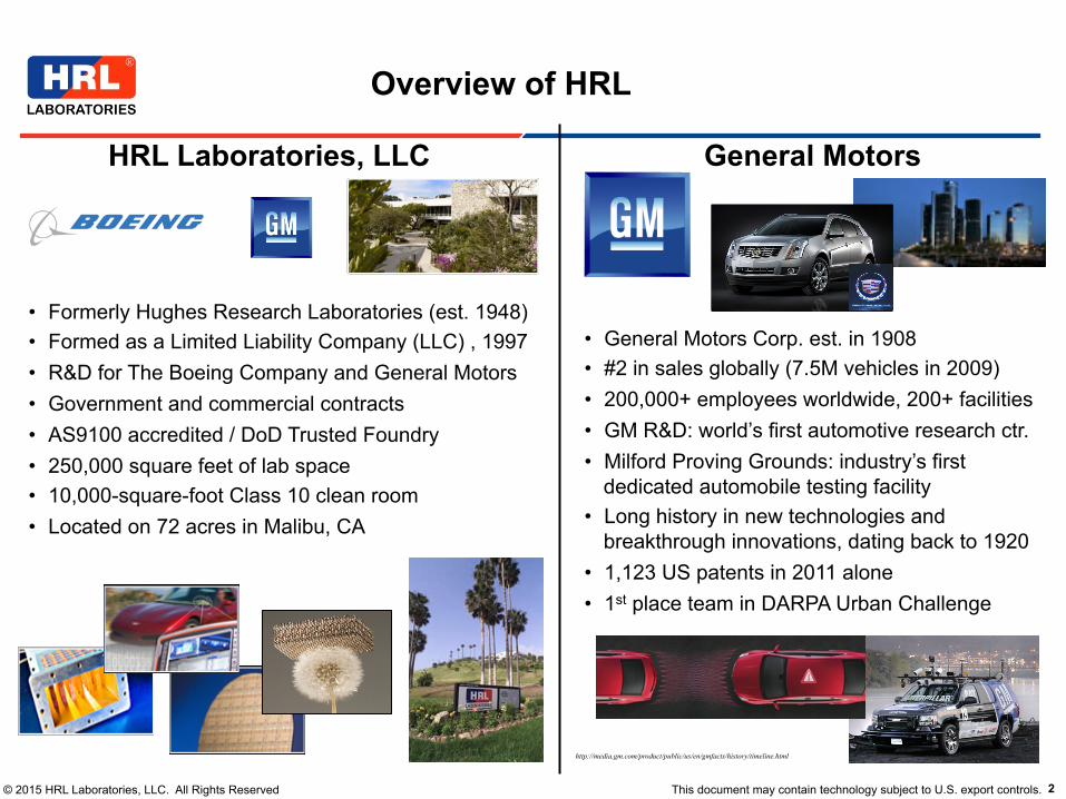
© 2015 HRL Laboratories, LLC. All Rights Reserved This document may contain technology subject to U.S. export controls. 2
Overview of HRL
HRL Laboratories, LLC
• Formerly Hughes Research Laboratories (est. 1948) • Formed as a Limited Liability Company (LLC) , 1997 • R&D for The Boeing Company and General Motors • Government and commercial contracts • AS9100 accredited / DoD Trusted Foundry • 250,000 square feet of lab space • 10,000-square-foot Class 10 clean room • Located on 72 acres in Malibu, CA
General Motors
• General Motors Corp. est. in 1908 • #2 in sales globally (7.5M vehicles in 2009) • 200,000+ employees worldwide, 200+ facilities • GM R&D: world’s first automotive research ctr. • Milford Proving Grounds: industry’s first
dedicated automobile testing facility • Long history in new technologies and
breakthrough innovations, dating back to 1920 • 1,123 US patents in 2011 alone • 1st place team in DARPA Urban Challenge
http://media.gm.com/product/public/us/en/gmfacts/history/timeline.html

© 2015 HRL Laboratories, LLC. All Rights Reserved This document may contain technology subject to U.S. export controls. 3
• Introduction and Motivation
• Prelims for Remote Attestation
• Secure and Minimal Architecture for (Dynamic) Root of Trust (SMART)
• Future Directions
Outline

© 2015 HRL Laboratories, LLC. All Rights Reserved This document may contain technology subject to U.S. export controls. 4
Widening Range of Specialized/Embedded Devices
Automotive Systems RFIDs
Sensors and Actuators
SmartCards
Connected Devices
Industrial Systems Appliances
Smartphones and Watches

© 2015 HRL Laboratories, LLC. All Rights Reserved This document may contain technology subject to U.S. export controls. 5
• Smart watches, e.g., Apple, Samsung
• Smart glasses and personal (VR) displays, e.g., Google Glass, Oculus Rift, Samsung
• Smart footwear, e.g., Nike+
• Smart clothes and garments (outer and under)
Already Here or Coming Soon

© 2015 HRL Laboratories, LLC. All Rights Reserved This document may contain technology subject to U.S. export controls. 6 5
Recent Attacks ■ Stuxnet [1] • Infected controlling windows machines • Changed parameters of the PLC of the
centrifuges of Iranian nuclear reactors ■ Attacks against automotive controllers [2] • Internal controller-area network (CAN) • Exploiting one subsystem (e.g., bluetooth)
allows access to critical subsystems (e.g., braking)
■ Medical devices • Insulin pumps hack [3] • Implantable cardioverter defibrillator [4]
[1] W32.Stuxnet Dossier. Nicolas Falliere, Liam O Murchu and Eric Chien. Symantec 2011 [2] Comprehensive Experimental Analyses of Automotive Attack Surfaces. S. Checkoway et al. USENIX 2011 [3] Hacking Medical Devices for Fun and Insulin: Breaking the Human SCADA System. Jerome Radcliffe. Blackhat 2011 [4] Pacemakers and Implantable Cardiac Defibrillators: Software Radio Attacks and Zero-Power Defenses. S&P 2008
Notable Attacks on Embedded Systems
• Stuxnet [1] (also DUQU) • Infected controlling windows machines • Changed parameters of the PLC (programmable logic
controller) used in centrifuges of Iranian nuclear reactors
• Attacks against automotive controllers [2] • Internal controller-area network (CAN) • Exploitation of one subsystem (e.g., bluetooth)
allows access to critical subsystems (e.g., braking) • Medical devices
• Insulin pumps hack [3] • Implantable cardiac defibrillator [4]
• Most effective CPS attacks are remote infestations, i.e., not physical attacks
[1] W32.Stuxnet Dossier, Symantec 2011 [2] Comprehensive Experimental Analyses of Automotive Attack Surfaces, USENIX 2011 [3] Hacking Medical Devices for Fun and Insulin: Breaking the Human SCADA System, Blackhat 2011 [4] Pacemakers and Implantable Cardiac Defibrillators: Software Radio Attacks and Zero-Power Defenses, S&P 2008

© 2015 HRL Laboratories, LLC. All Rights Reserved This document may contain technology subject to U.S. export controls. 7
Specialized/Embedded Devices in the Automotive Domain
According to sensormag.com http://www.sensorsmag.com/product/automotive-sensor-market-worth-3578-billion-2022 Market report on "Automotive Sensor Market by Product (Pressure, temperature, level, speed, MEMS, oxygen, Nox), Application (powertrain, safety & control, vehicle security, alternative fuel, telematics) and Geography - Forecast & Analysis to 2013 – 2022” is expecting market to grow at a CAGR of 8.6% from 2014 to 2022 and reach $35.78 Billion in 2022.
Figure source: http://www.can-cia.org/index.php?id=1691
“Modern cars have become complex digital devices, which can contain over 70 electronic control units (ECUs) …” https://www.escar.info/escar-usa.html

© 2015 HRL Laboratories, LLC. All Rights Reserved This document may contain technology subject to U.S. export controls. 8
Trusted Computing Group (TCG) Automotive Focus
Figure source: TCG TPM 2.0 Automotive Thin Profile, March 2015 http://www.trustedcomputinggroup.org/resources/tcg_tpm_20_library_profile_for_automotivethin
“Given the diverse use cases inside the vehicle, it is reasonable to describe a vehicle as a composite industrial control system network with one or more Internet Gateways and one or more human user interfaces.” -- TCG TPM 2.0 Automotive Thin Profile, March 16th 2015
Page 6 TCG Published Level 00 Version 1.0
March 16, 2015 Copyright © TCG 2015
4 Scenarios for usage of Automotive-Thin Profile (Informative)
4.1 Introduction
This specification defines a TPM 2.0 Library Profile for Automotive-Thin. Significant characteristics of an Automotive-Thin TPM include:
1. Often deployed in support of resource-constrained ECUs to support their integrity and attestation for remote maintenance services
2. Supports storage of ECU firmware measurements, creation of integrity digests, and creations of signatures on integrity digests
3. After receiving a firmware update or patch, an ECU may use an Automotive-Thin TPM to verify signatures and to help confirms to a Remote Center that an update installation was completed successfully
.
4.2 Example of both Automotive-Rich and Automotive-Thin TPMs in a vehicle
Here we show an example where both Automotive-Rich and Automotive-Thin TPMs are deployed in a vehicle body. Message flows based on this example are described below in Sections 4.5 and 4.6.
Figure 2: Automotive-Rich and Automotive-Thin TPMs implemented in a vehicle
As mentioned above in Section 2 above, the number of ECUs in a modern vehicle is commonly over 100. For the case where each ECU has its own Automotive-Thin TPM, the number of Automotive-Thin TPMs may be over 100. This is the reason that the Automotive-Rich Profile could have support for individual “shadowing” in NVRAM and also for aggregating of the integrity measurements from the many Automotive-Thin TPMs.
Head Unit / Gateway
HW
4 Core < RAM
OS
Others
Applications
TPM
Head Unit / Gateway
HW
1~2 core RAM
OS
Others
Applications
TPM
ECU
HW1 core RAM
Others
Application
TPM
ECU
HW1 core RAM
Others
Application
TPM
ECU
HW1 core RAM
Others
Application
TPM
More resources, Auto-Rich
Limited resources,Auto-Thin

© 2015 HRL Laboratories, LLC. All Rights Reserved This document may contain technology subject to U.S. export controls. 9
Trusted Computing Group (TCG) Automotive Focus
Page 8 TCG Published Level 00 Version 1.0
March 16, 2015 Copyright © TCG 2015
4.4 Message flows for Remote Maintenance
Here we show an example of message flows for a use case of remote maintenance of firmware, where an integrity digest is used to verify an ECU firmware update or patch. Because of this focus, details related only to real time vehicle operations performed by ECUs (brakes, lights, engine, etc.) will be ignored. Remote vehicle maintenance could be done periodically and/or in vehicle off times (i.e. vehicle parked with ignition off). When vehicle recalls could occur based only on software implementation defects, not caused by hardware issues, the remote vehicle maintenance method could be used to solve these recall issues without a dealer or repair shop visit.
Figure 4 shows the message flow for each component (Head Unit/Gateway or ECU) for remote maintenance handled by Automotive-Rich, and -Thins.
Figure 4: Message Flow for Remote Vehicle Maintenance
In this figure, the role of Vehicle Manufacturing Center (VMC) is also included.
4.5 Message Flows where Head Unit checks ECU signatures
Here we show an example of message flows where the Head Unit or Gateway uses its Automotive-Rich TPM to check the signatures on integrity reports created by each ECU with its own Automotive-Thin TPM. Each ECU’s Automotive-Thin TPM has been pre-provisioned with an Endorsement Key (EK) at the time of ECU installation (during vehicle manufacturing or when replaced by a dealer or repair shop). Each ECU’s Automotive Thin TPM EK public key has been registered with the Head Unit or Gateway and the Remote Center and the Remote Center has generated an EK certificate at the time of ECU installation in the vehicle.
Auto-RichInstalled
Auto-ThinInstalled
Update Data
FWDigest
FWDigest
Update Data
TNC
Remote Center• Recognize a status of the vehicle by surveying FW Digest• Select & send a suitable update data
“TPM 2.0 for Automotive Thin” installed in ECU• Measure ECU FW to create a digest & sign to the digest
“TPM 2.0 for Automotive Rich” installed in Head unit• Work as “TPM 2.0 for whole vehicle”; furthermore• Gateway between the Remote Center and ECU
Head Unit / Gateway
HW
1~2 core RAM
OS
Others
Applications
TPM
ECU
HW1 core RAM
Others
Application
TPM
Figure above shows the message flow for each component (Head Unit/Gateway or ECU) for remote maintenance handled by Automotive-Rich, and -Thins. Figure source: TCG TPM 2.0 Automotive Thin Profile, March 2015 http://www.trustedcomputinggroup.org/resources/tcg_tpm_20_library_profile_for_automotivethin

© 2015 HRL Laboratories, LLC. All Rights Reserved This document may contain technology subject to U.S. export controls. 10
– Memory: program (e.g., 128KB Flash) and data (e.g., 4KB SRAM) – Typically built around an MCU (serving as CPU), Integrated clock – As well as:
– Communication interfaces (USB, CAN, Serial, Ethernet, etc.) – Analog to digital converters
– Examples: TI MSP430, Atmel AVR, Raspberry Pi
Low-end Embedded Devices
(Automotive-Thin in TCG Language)
2
Low-end Embedded Devices
■ Low cost, low power devices ■ Built around a Micro-controller Unit
(MCU) ■ Limited: • Memory – 4 KB Data Memory (SRAM) – 128KB Program Memory (Flash)
• Power • computation capabilities
■ For example • MSP430 • AVR

© 2015 HRL Laboratories, LLC. All Rights Reserved This document may contain technology subject to U.S. export controls. 11
• Contrast with high-end processors, e.g., ARM, Intel
• Possibly built-in cryptographic support/functions, e.g., TPM, secure boot, HW-based isolation
• Notable example: ARM Trustzone
High-end Embedded Devices
(Automotive-Rich in TCG Language)
Figure sources: http://www.arm.com/products/processors/technologies/trustzone/index.php

© 2015 HRL Laboratories, LLC. All Rights Reserved This document may contain technology subject to U.S. export controls. 12
• Unrealistic that every processor will be Trustzone-like, maybe (at most) 1 or 2 in the system
• Cost is a serious limitation
• “Trust Anchors” in a large CPS can be built on more powerful CPUs, they can attest other CPUs/MCUs
Issues in a (Heterogeneous) CPS
CPS Definition: “A cyber-physical system (CPS) is a system where there is tight coordination of the system’s computational and physical elements, though sensors and actuators”

© 2015 HRL Laboratories, LLC. All Rights Reserved This document may contain technology subject to U.S. export controls. 13
• Not a final solution for securing heterogeneous CPS, more research still needed (also ongoing work to standardize it)
• A description of design and performance of an essential component for remote attestation for low-end (automotive-thin) embedded devices
• A blueprint for how the entire system can be attested
• Outline of future direction and research
Disclaimer: This Talk is …

© 2015 HRL Laboratories, LLC. All Rights Reserved This document may contain technology subject to U.S. export controls. 14
• Introduction and Motivation
• Prelims for Remote Attestation
• Secure and Minimal Architecture for (Dynamic) Root of Trust (SMART)
• Future Directions
Outline
© 2015 HRL Laboratories, LLC. All Rights Reserved This document may contain technology subject to U.S. export controls. 15
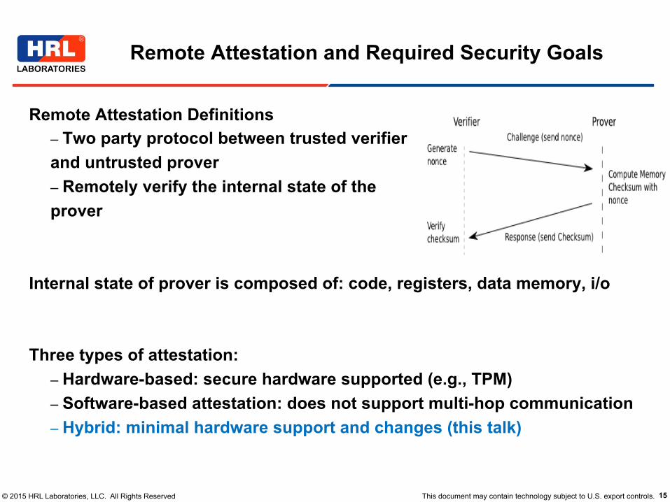
Remote Attestation Definitions – Two party protocol between trusted verifier and untrusted prover – Remotely verify the internal state of the prover
Internal state of prover is composed of: code, registers, data memory, i/o Three types of attestation:
– Hardware-based: secure hardware supported (e.g., TPM) – Software-based attestation: does not support multi-hop communication – Hybrid: minimal hardware support and changes (this talk)
Remote Attestation and Required Security Goals
7
Remote attestation
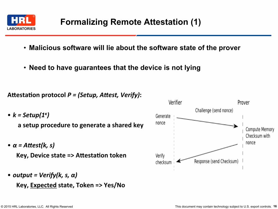
■ Malicious software will lie about the software state of the prover ■ Need to have guarantees that the device is not lying
© 2015 HRL Laboratories, LLC. All Rights Reserved This document may contain technology subject to U.S. export controls. 16
• Malicious software will lie about the software state of the prover
• Need to have guarantees that the device is not lying
Formalizing Remote Attestation (1)
7
Remote attestation
■ Malicious software will lie about the software state of the prover ■ Need to have guarantees that the device is not lying
A#esta(on protocol P = (Setup, A,est, Verify): • k = Setup(1κ)
a setup procedure to generate a shared key
• α = A,est(k, s) Key, Device state => A#esta(on token
• output = Verify(k, s, α) Key, Expected state, Token => Yes/No

© 2015 HRL Laboratories, LLC. All Rights Reserved This document may contain technology subject to U.S. export controls. 17
Formalizing Remote Attestation (2)
(1) Pick a random
challenge
(2) State of prover +
challenge + key
(3) Verify that the returned output corresponds to expected state
Attestation protocol may also return the exact state
© 2015 HRL Laboratories, LLC. All Rights Reserved This document may contain technology subject to U.S. export controls. 18
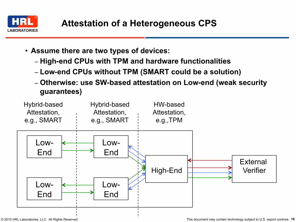
• Assume there are two types of devices: – High-end CPUs with TPM and hardware functionalities – Low-end CPUs without TPM (SMART could be a solution) – Otherwise: use SW-based attestation on Low-end (weak security
guarantees)
Attestation of a Heterogeneous CPS
External Verifier
High-End
Low-End
Low-End
Low-End
Low-End
HW-based Attestation, e.g.,TPM
Hybrid-based Attestation,
e.g., SMART
Hybrid-based Attestation,
e.g., SMART

© 2015 HRL Laboratories, LLC. All Rights Reserved This document may contain technology subject to U.S. export controls. 19
Outline
• Introduction and Motivation
• Prelims for Remote Attestation
• Secure and Minimal Architecture for (Dynamic) Root of Trust (SMART)
• Future Directions

© 2015 HRL Laboratories, LLC. All Rights Reserved This document may contain technology subject to U.S. export controls. 20
Systematic Analysis of Required Features
Remote Attestation
Prover Authentication
Authenticated Integrity of Prover’s
Internal State
MAC function + helper code
Prover Secret Key
Verifier Challenge
Restricted Access Secret Key Storage
Atomic Execution
Non-malleable Code = ROM
© 2015 HRL Laboratories, LLC. All Rights Reserved This document may contain technology subject to U.S. export controls. 21
1. Secure Key Storage (as little as 180 bits) – Required for remote Prover – Enables Prover authentication
2. Trusted ROM code memory region – Read-only means integrity: computes response – Accesses/uses key (exclusively)
3. MCU access control – Grants access to key from within ROM code only
4. Atomicity of ROM code execution – Disable/enable interrupts – No invocation other than from the start
Building Blocks

© 2015 HRL Laboratories, LLC. All Rights Reserved This document may contain technology subject to U.S. export controls. 22
Scope of Modifications to MCUs
(a) AVR: Dark gray boxes represent logic added to the processor. Corecontrol signals provide information about internal processor status tomemory bus controls.
(b) MSP430: Memory backbone was modified to control access toROM and K. Since MSP430 is based on Von Neumann architecture,concurrent access can occur to different memory parts (e.g., instruc-tion fetch and read data). In that case, memory backbone arbitratesbus access and temporarily saves/restores data.
Figure 4: Modifications to AVR and MSP430.
as one line of code, although they have very differentimpact on synthesized hardware. We synthesized theoriginal and SMART-ified designs for both AVR andMSP430. This provides an initial estimate of the im-pact of SMART on the final devices. Synthesizing isthe act of transforming (or compiling) the design froma high-level description language (Verilog or VHDL)into a set of wires and elementary gates that serve asbuilding blocks of an Application-Specific IntegratedCircuit (ASIC).
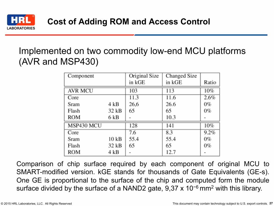
Synthesis needs to be performed for a specific targethardware. We used the library from UMC 180nmprocess [18] and Synopsys Design Compiler [44].For better performance, RAM and ROM memorieswere generated with a specific tool [17], [16]. Flashmemory numbers were gleaned from publicly avail-able information [10]. Results can vary substantiallydepending on many parameters, such as: requiredmaximum frequency, latency, placement and routingand availability of better memory IP. However, ourcurrent measurements (in Table 3) show that the impactof SMART on surface area is minimal. Adding SMARTto both AVR and MSP430 caused only a 10% increasein their respective surface areas. As mentioned before,most of that added area is due to the ROM housing
SMART code. Modifications to the core required only1K and 0.7K gate equivalents in AVR and MSP430,respectively. This could probably be reduced as we didnot perform optimizations.
Component Size in kGEOrig. with SMART Ratio
AVR MCU 103 113 10%Core 11.3 11.6 2.6%SRAM 4 kB 26,6 26.6 0%Flash 32 kB 65 65 0%ROM 6 kB - 10.3 -MSP430 MCU 128 141 10%Core 7.6 8.3 9.2%SRAM 10 kB 55.4 55.4 0%Flash 32 kB 65 65 0%ROM 4 kB - 12.7 -
Table 3: Comparison of chip surface used by each com-ponent of the original MCU to its modified version.kGE stands for thousands of Gate Equivalents (GE-s). One GE is proportional to the surface of the chipand computed form the module surface divided by thesurface of a NAND2 gate, 9, 37 ⇤ 10�6mm2 with thislibrary.
MSP430: Memory backbone was modified to control access to ROM and key. MSP430 is based on Von Neumann architecture, concurrent access can occur to different memory parts (e.g., instruction fetch and read data). In that case, memory backbone arbitrates bus access and temporarily saves/restores data.
(a) AVR: Dark gray boxes represent logic added to the processor. Corecontrol signals provide information about internal processor status tomemory bus controls.
(b) MSP430: Memory backbone was modified to control access toROM and K. Since MSP430 is based on Von Neumann architecture,concurrent access can occur to different memory parts (e.g., instruc-tion fetch and read data). In that case, memory backbone arbitratesbus access and temporarily saves/restores data.
Figure 4: Modifications to AVR and MSP430.
as one line of code, although they have very differentimpact on synthesized hardware. We synthesized theoriginal and SMART-ified designs for both AVR andMSP430. This provides an initial estimate of the im-pact of SMART on the final devices. Synthesizing isthe act of transforming (or compiling) the design froma high-level description language (Verilog or VHDL)into a set of wires and elementary gates that serve asbuilding blocks of an Application-Specific IntegratedCircuit (ASIC).
Synthesis needs to be performed for a specific targethardware. We used the library from UMC 180nmprocess [18] and Synopsys Design Compiler [44].For better performance, RAM and ROM memorieswere generated with a specific tool [17], [16]. Flashmemory numbers were gleaned from publicly avail-able information [10]. Results can vary substantiallydepending on many parameters, such as: requiredmaximum frequency, latency, placement and routingand availability of better memory IP. However, ourcurrent measurements (in Table 3) show that the impactof SMART on surface area is minimal. Adding SMARTto both AVR and MSP430 caused only a 10% increasein their respective surface areas. As mentioned before,most of that added area is due to the ROM housing
SMART code. Modifications to the core required only1K and 0.7K gate equivalents in AVR and MSP430,respectively. This could probably be reduced as we didnot perform optimizations.
Component Size in kGEOrig. with SMART Ratio
AVR MCU 103 113 10%Core 11.3 11.6 2.6%SRAM 4 kB 26,6 26.6 0%Flash 32 kB 65 65 0%ROM 6 kB - 10.3 -MSP430 MCU 128 141 10%Core 7.6 8.3 9.2%SRAM 10 kB 55.4 55.4 0%Flash 32 kB 65 65 0%ROM 4 kB - 12.7 -
Table 3: Comparison of chip surface used by each com-ponent of the original MCU to its modified version.kGE stands for thousands of Gate Equivalents (GE-s). One GE is proportional to the surface of the chipand computed form the module surface divided by thesurface of a NAND2 gate, 9, 37 ⇤ 10�6mm2 with thislibrary.
AVR: Dark gray boxes represent logic added to the processor. Core control signals provide information about internal processor status to memory bus controls.
© 2015 HRL Laboratories, LLC. All Rights Reserved This document may contain technology subject to U.S. export controls. 23
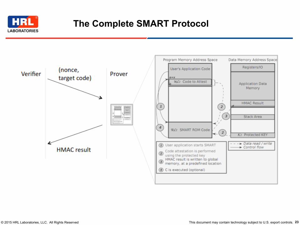
The Complete SMART Protocol

© 2015 HRL Laboratories, LLC. All Rights Reserved This document may contain technology subject to U.S. export controls. 24
Required Access Control Logic for Secret Key
GT
LT
A[15:0]
B[15:0]
C O M P M 1 6
GT
LT
A[15:0]
B[15:0]
C O M P M 1 6
PC
GT
LT
A[15:0]
B[15:0]
C O M P M 1 6
GT
LT
A[15:0]
B[15:0]
C O M P M 1 6
DATA_ADDR_BUS
KEY_LOW
ROM_MAX
KEY_HIGH
ROM_MIN
AND3
Internal_resetOR2
AND4
SRAM_BUS
M U X F 8I0
I1
S
O DATA_BUS
KEY_MEM_BUS
Figure 3: Schematic view of access control for attestation key.
A1 Cryptographic checksum C computed by PRVcannot be forged. Since C is a result of secureHMAC function (e.g., HMAC-SHA) we assumethat, for any ADV – external to PRV – that ob-serves a polynomial number of such checksums,finding HMAC collisions and/or learning bits ofthe attestation key is infeasible.
A2 Physical and hardware-based attacks on PRV arebeyond ADV’s capabilities.
A3 Attestation key K can be accessed only fromwithin ROM-resident SMART code. This is guar-anteed by MCU-based access controls.
A4 SMART code cannot be modified since it residesin ROM.
A5 SMART code can be only invoked at its be-ginning. The hardware checks that, except forthe very first instruction in RC, if the programcounter is in RC range, then the previous executedinstruction must also be in ROM.
A6 RC execution can only terminate at the very lastinstruction address in RC. The hardware checksthat, except for the very last instruction in RC,if the program counter is not in RC range, thenthe previous instructions must also be outside RCrange.
A7 Upon each invocation of SMART, all interrupts
are disabled 8 and remain so if, upon completionof SMART, control is passed to HC.
A8 K cannot be extracted by any software-basedADV internal to PRV . Upon completion ofSMART execution, K is no longer accessible.Also, all memory used by SMART code is se-curely erased. The only value based (statisticallydependent) on K is the output C.
A9 For each invocation, SMART computes C basedon the contents of the requested memory segment[a, b]. Although C is guaranteed to be computedcorrectly, it may or may not result in PRV pass-ing attestations, since [a, b] might be previouslycorrupted by ADV .
A10 Any erroneous state (e.g., violation of assertionsA3, A5, A6) leads to a hardware reset. Upon reset,all data memory and registers are erased, whichprevents K leakage. This boot-time memory era-sure also guarantees that, if power loss occursduring SMART execution, no information aboutK is retained in memory.
A11 Observing normal execution of SMART shouldleak no information about K. Therefore, SMARTexecution time and amount of memory used mustnot be key-dependent.
8. From the security perspective, executing SMART with inter-rupts disabled is redundant with respect to assertions A5 and A6.However, this (assertion A7) prevents a reset if an interrupt occursduring SMART execution, thus improving reliability.

© 2015 HRL Laboratories, LLC. All Rights Reserved This document may contain technology subject to U.S. export controls. 25
• If Prover infected, ROM code and malware share the same MCU resources
– Malware can set up execution environment to compromise ROM code and extract key
– Malware can schedule interrupts to occur asynchronously while key (or some function thereof) is in main memory
– Malware can use code gadgets in ROM to access key – Return-Oriented Programming (ROP)
– ROM code might leave traces of key in memory after its execution
Design and Operation Issues

© 2015 HRL Laboratories, LLC. All Rights Reserved This document may contain technology subject to U.S. export controls. 26
– Atomic ROM code execution: enforced in hardware – Enter at first instruction – Exit at last instruction
– ROM code instrumented to check for memory safety – Used DEPUTY – Upon detecting error reboot and clear memory
– Interrupts disabled immediately upon ROM entry – Before key usage (enabled upon exit) – DINT instruction must itself be atomic
– Erase key-related material before end of execution
Countermeasures
© 2015 HRL Laboratories, LLC. All Rights Reserved This document may contain technology subject to U.S. export controls. 27
Cost of Adding ROM and Access Control
Implemented on two commodity low-end MCU platforms (AVR and MSP430)
Comparison of chip surface required by each component of original MCU to SMART-modified version. kGE stands for thousands of Gate Equivalents (GE-s). One GE is proportional to the surface of the chip and computed form the module surface divided by the surface of a NAND2 gate, 9,37 x 10⁻⁶ mm2 with this library.

© 2015 HRL Laboratories, LLC. All Rights Reserved This document may contain technology subject to U.S. export controls. 28
HMAC Performance and Effort to Implement
application areas, e.g., in the automotive industry,utility meters, consumer devices and peripherals.
AVR and MSP430 also have some major architec-tural differences. Notably, MSP430 is a 16-bit VonNeumann architecture processor with common dataand code address spaces. Whereas, AVR is an 8-bit Harvard architecture processor that has separateaddress spaces for data and program memory. Anotherprominent difference is in the instruction set: AVR isa RISC architecture with most instructions requiring asingle 16-bit word and executing in one clock cycle.In contrast, MSP430 can perform multiple memoryaccesses within a single instruction. Its instructionexecution time can range from 1 to 6 clock cycles,and instruction length can vary from 16 to 48 bits.
The differences between AVR and MSP430 makesthem good representatives of architectures commonlyused in many modern embedded systems.
6.1. Implementation Details
SMART implementation consists of three main com-ponents:
• Processor modifications to add ROM code, keystorage and memory access controls.
• Largely architecture-independent SMART routinestored in ROM that implements Algorithm 1.This C code has a small number of architecture-dependent lines.
• One or more software protocol implementationsthat utilize the SMART primitive.
Implementation on AVR and MSP430 Cores. Wefirst implemented the hardware part of SMART onthe AVR processor, an Atmega103 [5] clone fromthe OpenCores Project [31]. Figure 4a illustrates theexecution core and its memory. Parts that had to bemodified or added are shaded. They mainly correspondto memory and memory access controls on memorybuses.
Next, we implemented SMART on MSP430. Weused the open-source OpenMSP430 core from theOpenCores Project [31] and ported SMART to it. Theport consists of processor modifications, adaptation ofROM code to MSP430 architecture as well as testingand synthesizing the resulting core. These tasks wereperformed in one week by one developer with mod-erate Verilog knowledge and no previous experiencewith the OpenMSP430 core. Processor modificationswere limited to implementing and adding modulesfor ROM code and key memory. In addition, minormodifications and address checks were required in the
Component Original ChangedLines Lines Ratio
AVR, core (VHDL) 3932 151 3.84%AVR, tests 2244 760MSP430, core (Verilog) 4593 182 3.96%MSP430, tests 17665 1122
Table 1: Changes made (in # of HDL lines of code) inAVR and MSP430 processors, respectively, excludingcomments and blank lines.
Data Size Cycles Time at 8MHz1 KByte 2302281 287 ms
512 Bytes 1281049 160 ms32 Bytes 387471 48 ms
Table 2: HMAC execution timing.
memory backbone module of the OpenMSP430 core.The memory backbone module performs arbitration ofmemory accesses. Figure 4b presents required modifi-cations (shaded) for MSP430.
In both processors, less than 200 lines of code(Table 1) were changed to implement these modi-fications. In addition to processor modifications, weextended existing regression tests (or test benches) toverify correct implementation of each of assertion fromSection 4 that is relevant here: A3, A5, A6, and A10.ROM-Resident Code. This code corresponds to 487lines of portable C and uses a standard SHA-1 imple-mentation [13]. It requires 4KBytes of ROM for theAVR and 6KBytes for MSP430. It executes in 10-s to100-s of milliseconds (see Table 2), depending on thesize of HC to attest.
Memory usage in SMART has to be carefully man-aged. SMART code cannot reserve memory for its ownusage. Memory should only be allocated on the stack(i.e. local functions variables). It should not attemptto use global variables or heap allocated memory.Doing so allows us to avoid relying on untrusted data.Finally, the code is compiled and linker scripts are usedto generate the ROM image suitable to the modifiedprocessor.Hardware Footprint. Simulating the design demon-strates its functional status. Whereas, comparing thenumber of lines of code of its implementation pro-vides insights into the amount of effort required toimplement SMART on a given MCU. However, this isinsufficient to assess real impact of SMART in termsof hardware overhead, i.e., surface increase due to itspresence on an actual manufactured device. A singleline of HDL can add a simple wire, a register or anentire memory block; each of these would be counted
HMAC is the most expensive operation to perform attestation in SMART
application areas, e.g., in the automotive industry,utility meters, consumer devices and peripherals.
AVR and MSP430 also have some major architec-tural differences. Notably, MSP430 is a 16-bit VonNeumann architecture processor with common dataand code address spaces. Whereas, AVR is an 8-bit Harvard architecture processor that has separateaddress spaces for data and program memory. Anotherprominent difference is in the instruction set: AVR isa RISC architecture with most instructions requiring asingle 16-bit word and executing in one clock cycle.In contrast, MSP430 can perform multiple memoryaccesses within a single instruction. Its instructionexecution time can range from 1 to 6 clock cycles,and instruction length can vary from 16 to 48 bits.
The differences between AVR and MSP430 makesthem good representatives of architectures commonlyused in many modern embedded systems.
6.1. Implementation Details
SMART implementation consists of three main com-ponents:
• Processor modifications to add ROM code, keystorage and memory access controls.
• Largely architecture-independent SMART routinestored in ROM that implements Algorithm 1.This C code has a small number of architecture-dependent lines.
• One or more software protocol implementationsthat utilize the SMART primitive.
Implementation on AVR and MSP430 Cores. Wefirst implemented the hardware part of SMART onthe AVR processor, an Atmega103 [5] clone fromthe OpenCores Project [31]. Figure 4a illustrates theexecution core and its memory. Parts that had to bemodified or added are shaded. They mainly correspondto memory and memory access controls on memorybuses.
Next, we implemented SMART on MSP430. Weused the open-source OpenMSP430 core from theOpenCores Project [31] and ported SMART to it. Theport consists of processor modifications, adaptation ofROM code to MSP430 architecture as well as testingand synthesizing the resulting core. These tasks wereperformed in one week by one developer with mod-erate Verilog knowledge and no previous experiencewith the OpenMSP430 core. Processor modificationswere limited to implementing and adding modulesfor ROM code and key memory. In addition, minormodifications and address checks were required in the
Component Original ChangedLines Lines Ratio
AVR, core (VHDL) 3932 151 3.84%AVR, tests 2244 760MSP430, core (Verilog) 4593 182 3.96%MSP430, tests 17665 1122
Table 1: Changes made (in # of HDL lines of code) inAVR and MSP430 processors, respectively, excludingcomments and blank lines.
Data Size Cycles Time at 8MHz1 KByte 2302281 287 ms
512 Bytes 1281049 160 ms32 Bytes 387471 48 ms
Table 2: HMAC execution timing.
memory backbone module of the OpenMSP430 core.The memory backbone module performs arbitration ofmemory accesses. Figure 4b presents required modifi-cations (shaded) for MSP430.
In both processors, less than 200 lines of code(Table 1) were changed to implement these modi-fications. In addition to processor modifications, weextended existing regression tests (or test benches) toverify correct implementation of each of assertion fromSection 4 that is relevant here: A3, A5, A6, and A10.ROM-Resident Code. This code corresponds to 487lines of portable C and uses a standard SHA-1 imple-mentation [13]. It requires 4KBytes of ROM for theAVR and 6KBytes for MSP430. It executes in 10-s to100-s of milliseconds (see Table 2), depending on thesize of HC to attest.
Memory usage in SMART has to be carefully man-aged. SMART code cannot reserve memory for its ownusage. Memory should only be allocated on the stack(i.e. local functions variables). It should not attemptto use global variables or heap allocated memory.Doing so allows us to avoid relying on untrusted data.Finally, the code is compiled and linker scripts are usedto generate the ROM image suitable to the modifiedprocessor.Hardware Footprint. Simulating the design demon-strates its functional status. Whereas, comparing thenumber of lines of code of its implementation pro-vides insights into the amount of effort required toimplement SMART on a given MCU. However, this isinsufficient to assess real impact of SMART in termsof hardware overhead, i.e., surface increase due to itspresence on an actual manufactured device. A singleline of HDL can add a simple wire, a register or anentire memory block; each of these would be counted
Changes made (in # of HDL lines of code) in AVR and MSP430 processors, respectively, excluding comments and blank lines.
© 2015 HRL Laboratories, LLC. All Rights Reserved This document may contain technology subject to U.S. export controls. 29
Secure Remote Attestation for Low-end Devices
• Introduction and Motivation
• Prelims for Remote Attestation
• Secure and Minimal Architecture for (Dynamic) Root of Trust (SMART)
• Future Directions

© 2015 HRL Laboratories, LLC. All Rights Reserved This document may contain technology subject to U.S. export controls. 30
• Asymmetric vs symmetric cryptography on Prover
• Automated synthesis of attestation and formal verification of implementation
• Platform for more sophisticated or specialized services: secure
code update, secure erasure, secure boot
• More experiments and implementation on various platforms/CPS
• Verifier Authentication (very relevant to mitigate denial-of-service)
Open Issues and Research Directions

© 2015 HRL Laboratories, LLC. All Rights Reserved This document may contain technology subject to U.S. export controls. 31
Questions?

© 2015 HRL Laboratories, LLC. All Rights Reserved This document may contain technology subject to U.S. export controls. 32
SMART as an API
Key Protection Guarantee. Assertion A3 impliesthat K is not directly available to untrusted software.Assertions A5 and A6 guarantee that code reuse attacksto recover K are impossible. A10 implies that, whenerror condition occurs, execution is stopped and noinformation about K is leaked. A11 guaranties thatside-channels cannot be used to gather informationabout K by untrusted software executing on the MCU.Other side-channels commonly used in key recov-ery attacks rely on power consumption analysis andelectromagnetic emanations [34]. However, these arehardware/physical attacks 9.
Given the above assertions and the key protectionguarantee and assuming that VRF receives and suc-cessfully verifies C, we argue that postulated securityobjectives are satisfied:Prover Authentication. If C is correctly computedand n is a random nonce of sufficient bit-length, VRFconcludes that C was computed by PRV within theinterval of time between the initial request messageand the receipt of C. This yields fresh authenticationof PRV .External Verification. Assertions A1-A8 imply that Cwas computed by SMART code on PRV . Therefore,memory region [a, b] on PRV contained code or dataexpected by VRF .Guaranteed Execution. Assertion A6 implies that,immediately after computing C, PRV executes codeat x, if xflag is set. If C is deemed correct by VRFand x = a, VRF is assured that the expected code atlocation a was executed.
5. Other Uses of SMART
In this section we describe several techniques thatcan be implemented using SMART as a building block.
5.1. Remote Attestation of Parts of Memory
The most natural usage of SMART is to attest amemory segment and verify that it contains data (orcode) that it is expected to contain. This can beachieved by invoking SMART with the start and endaddresses of the memory range to be attested, as shownin Algorithm 2.
9. We note that these side-channels might be exploitable in veryspecific cases by a local attacker, e.g., if hardware to perform suchmeasurements is available as a peripheral of the device, e.g., acoulomb counter that measures remaining battery power. This could,in theory, provide information on power consumption of SMARTcode. We assume that such features are not available on the device.
Algorithm 2: SMART usage to attest a memoryrange.
input : n nonce sent by VRFa start address to attestb end address to attestH HMAC result (global variable)
output: HMAC outputbegin
SMART(a, b, ;, False,n,&H ,;);Send(H);
end
5.2. Remote Proof of Reset
Some applications need to ensure that a device hasbeen reset successfully. This can be easily done withSMART, as shown in Algorithm 3. HMAC guaranteesthat the reset function (R) has been verified andexecuted. Here, we assume that output of HMAC is noterased during reset, e.g., stored in Flash or EEPROM.
5.3. Attested Reading of Measurements
Some applications need to make sure that valuesread from a peripheral device cannot be forged bymalware possibly present on that device. For example,large-scale incorrect reports of current electricity con-sumption by smart meters might lead to power outages.Or, an IMD that returns incorrect values when queriedby a physician might result in an incorrect prescrip-tion issued to a patient, with potentially catastrophicconsequences. Predictably, attestation of measurementsshould provide: (1) freshness of the values read, (2)proof of reading the values from the peripheral and(3) integrity of the values.
Freshness is provided via a nonce, present by defaultin SMART invocation. Proof of reading the value isprovided by calling SMART to attest and run HC, thatreads the values. Finally, HC calls SMART a secondtime, as a normal HMAC function, to protect integrityof the read values. Algorithm 4 presents this primitive.
Although this approach, using hash chains, bearssome resemblance to the extend operation of a TPM,there are some important differences: HMAC attestseach output of SMART with the secret key of thedevice. This allows for a simpler design. Besidesintegrity, HMAC correctness confirms that it wasproduced by SMART. This is fundamentally differentfrom the extend operation preformed by a TPM, sinceintegrity of the PCR is enforced by hardware.
challenge memory range to
attest

© 2015 HRL Laboratories, LLC. All Rights Reserved This document may contain technology subject to U.S. export controls. 33
K. Eldefrawy, A. Francillon, D. Perito and G. Tsudik, SMART: Secure and Minimal Architecture for Establishing Dynamic Root of Trust, NDSS 2012.
A. Francillon, Q. Nguyen, K. Rasmussen and G. Tsudik, A Minimalist Approach to Remote Attestation, DATE 2014,
• full version in Crypto ePrint Archive: Report 2012/713.
For More Details