reliance fast/trantm arl0909 & arl0909r · install the ats as close as possible to the main...
TRANSCRIPT

INSTRUCTIONS FOR THE RELIANCE Fast/TranTM ARL0909 & ARL0909R
THE RELIANCE Fast/Tran IS NOT FOR "DO-IT-YOURSELF" INSTALLATION. It must be installed by a
qualified electrician thoroughly familiar with all applicable electrical and building codes. The Reliance Fast/Tran is an automatic transfer switch (ATS) purpose-designed to provide a safe and simple method of powering designated branch circuits from a permanently installed backup AC power source. The electrical-over-mechanical transfer switching and interlocking system prevents accidental feedback of backup power onto utility lines. The extremely high speed switching system avoids the electrical appliance shutdowns that often occur with other transfer switches when transitioning from backup power back to utility power. This ATS consists of a utility power source and a HSB supply 2-pole switch which feeds a common bus. The two switches are mechanically interlocked so that both sources cannot feed the common bus at the same time. The automatic transfer switch (ATS) is used for transferring electrical load from a utility power source to a home standby generator (HSB) power source. This transfer of electrical loads occurs automatically when the utility power source has failed or is absent. The HSB controller continually monitors the utility power source, when the utility power source is lost, a signal is sent to the generator to start, the HSB comes up to capacity, a signal is then sent to the ATS to close the utility power source supply line and transfer to HSB supply. The ATS prevents electrical feedback between two different power sources, for that reason, codes require ATS in all standby electrical systems installations. The utility power source supply line is continually monitored by the HSB control, once utility power is re-established and constant, a signal is sent to the HSB to come off line, a signal is also sent to the ATS to transfer from the HSB to the utility power source line. The HSB will then perform a cool down, shut off and be placed into the standby alert position. The HSB Engine Control Module ATS/OFF/MANUAL switch must be in the ATS position, and the ATS Control Module TEST/AUTO/OFF switch must be in the AUTO position for the automatic operation. This manual has been prepared for the purpose of familiarizing servicing dealer/installer with the design, application, installation and servicing of the equipment. Read the manual carefully and comply with all instructions. This manual or a copy of this manual should remain with the switch. Every effort has been taken to make sure that the contents of this manual are accurate and current. The manufacturer reserves the right to change, alter or otherwise improve this literature and the product at any time without prior notice and without any obligation or liability whatsoever. The manufacturer cannot anticipate every possible circumstance that might involve a hazard. The warnings in this manual, tags and decals affixed to the unit are, therefore, not all-inclusive. If using a procedure, work method or operating technique the manufacturer does not specifically recommend follow all codes to ensure safety for personnel. Many accidents are caused by failing to follow simple and fundamental rules, codes and precautions. Before installing, operating or servicing this equipment, read the SAFETY RULES carefully. The publications that cover the safe use of ATS and installation are the following NFPA 70, NFPA 70E, UL 1008 and UL 67. It is important to refer to the latest version of any standard/code to ensure correct and current information. All installations must comply with national, state and local codes. It is responsibility of the installer to perform an installation that will pass the final electrical inspection.
Fast/Tran TM
Carefully unpack the ATS. Inspect closely for any damage that might have occurred during shipment. Check that all packing material is completely removed from the ATS prior to installation. Handle ATS carefully when installing. Do not drop. Protect the ATS against impacts at all times and against construction grit and metal chips. Never install an ATS that is damaged. The ARL0909 (Champion Model 100949) is a NEMA 1 enclosure and must be installed indoors, no exceptions. The ARL0909R (Champion Model 100952) is a NEMA 3R enclosure. It is similar to the NEMA 1, except the NEMA 3R is weather proof for outdoor installation. Both are UL Listed and have stickers attached to them providing designation.

INSTALLING THE Fast/Tran TM ARL Series
WARNING: Be certain that the power from the main panel is turned off and all backup sources are locked out before starting this procedure. Failure to do so could result in serious injury or death. Remember, automatic start generators will start upon loss of utility mains power unless locked in the “OFF” position. Consult the HSB instruction manual for positive lock-out procedures. CAUTION: Consult all local and National electrical codes for proper wiring methods for all wiring. Use a torque wrench to tighten the conductors, make sure not to overtighten, or damage to installation base could occur. If not tightened properly, a loose connection would result, causing excessive heat, which could result and damage to the base. Conductor sizes must be adequate to handle the maximum current to which they will be subjected to. The installation must comply fully with all applicable codes, standards and regulations. Conductors must be properly supported, of approved insulated qualities, protected by approved conduit, and the correct wire gauge size in accordance with all applicable codes. Before connecting wire cables to terminals, remove any surface oxides from the cable ends with a wire brush. All power cables must enter the enclosure through the knockouts. Install the ATS as close as possible to the main distribution panel. Mount the ATS vertically to a rigid supporting structure. To prevent ATS or enclosure box distortion, level all mounting points, use washers behind the mounting holes if needed.
1. Mount the ARL next to the main panel board (circuit breaker or fuse box). Install a large diameter conduit (1 ½ -
2 inch trade size recommended) between the two panels. Install a 100 ampere double-pole circuit breaker in the main panel board as a feeder for the ATS.
2. Strip wires 1/2 inch and install a Black L1, and Red L2 wire suitable for 100 amperes between the double-pole
feeder breaker in the main panel and the similarly-colored terminals on Utility Supply terminal block in the ATS. Install an insulated White wire of the same AWG between the neutral bar in the main panel and the White terminal on Utility Supply terminal block in the ATS. The neutral wire must be the same ampacity as the L1 and L2 power wiring. Install a suitable ground wire between the ground busses in the two panels.
3. Select the circuits to be powered by the backup generator. If the branch circuit conductor is long enough, you may want to pull it from the main panel board and reinstall it in the ATS. It is possible to use an additional wire and wire connector to extend the branch conductor in the main panel board through the conduit into the ATS. Install the branch circuit breakers in the ATS panel for those branch circuits to be powered by the generator. The ATS is UL listed for a number of 1-inch interchangeable breakers (see label on the inside cover of the ATS). If breakers are moved from the utility main panel board to the ATS, make certain the openings in the dead front created by removing those breakers from the main panel board are fitted with appropriate filler plugs. Connect each branch circuit conductor to its appropriate branch circuit breaker. Repeat for each of the selected circuits. The branch conductors must be connected to the same ampacity breakers as they were when they were in the main panel. Make certain that the total ampacity of the selected circuits does not exceed the maximum capacity of the generator.
4. Strip wires 1/2 inch and install a Black L1, Red L2, and White neutral wire suitable for 100 amperes between the
power output connector on the generator and the similarly-colored terminals on Generator Supply terminal block in the ATS. If the generator has a ground connector, install a ground wire between the generator and the ground bus in the ATS.
5. Route the multi-conductor cable from the generator to the 12-position center terminal block in the ATS. Strip wires 1/4 inch and connect each numbered wire to the terminal block in sequence from left to right starting with 1 in the left-most position. Each wire is connected by pushing the nylon release lever backwards to open the terminal clamp, inserting the stripped wire into the terminal opening, and releasing the terminal clamp. Care should be taken not to overstress the nylon release levers. Note that some of the terminal block positions are deliberately left unused (TB2-4 and TB2-8).
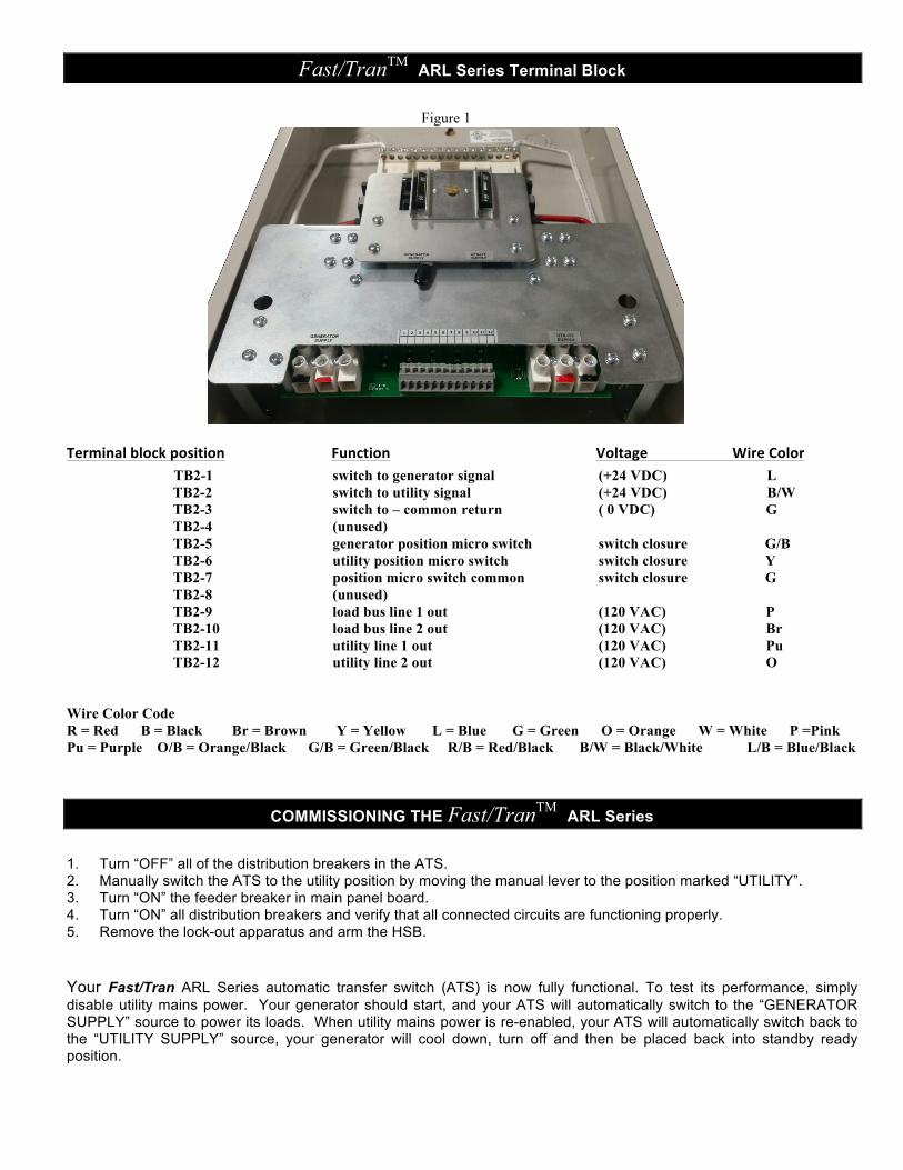
Fast/TranTM ARL Series Terminal Block
Figure 1
Terminal block position Function Voltage Wire Color TB2-1 switch to generator signal (+24 VDC) L
TB2-2 switch to utility signal (+24 VDC) B/W TB2-3 switch to – common return ( 0 VDC) G TB2-4 (unused) TB2-5 generator position micro switch switch closure G/B TB2-6 utility position micro switch switch closure Y TB2-7 position micro switch common switch closure G TB2-8 (unused) TB2-9 load bus line 1 out (120 VAC) P TB2-10 load bus line 2 out (120 VAC) Br TB2-11 utility line 1 out (120 VAC) Pu TB2-12 utility line 2 out (120 VAC) O
Wire Color Code R = Red B = Black Br = Brown Y = Yellow L = Blue G = Green O = Orange W = White P =Pink Pu = Purple O/B = Orange/Black G/B = Green/Black R/B = Red/Black B/W = Black/White L/B = Blue/Black
COMMISSIONING THE Fast/TranTM ARL Series
1. Turn “OFF” all of the distribution breakers in the ATS. 2. Manually switch the ATS to the utility position by moving the manual lever to the position marked “UTILITY”. 3. Turn “ON” the feeder breaker in main panel board. 4. Turn “ON” all distribution breakers and verify that all connected circuits are functioning properly. 5. Remove the lock-out apparatus and arm the HSB.
Your Fast/Tran ARL Series automatic transfer switch (ATS) is now fully functional. To test its performance, simply disable utility mains power. Your generator should start, and your ATS will automatically switch to the “GENERATOR SUPPLY” source to power its loads. When utility mains power is re-enabled, your ATS will automatically switch back to the “UTILITY SUPPLY” source, your generator will cool down, turn off and then be placed back into standby ready position.

Fast/TranTM ARL Series Automatic Transfer Switch Specifications
Model Number Enclosure
Style Maximum
Amps Nominal
Volts
ARL0909 (100949) NEMA 1 indoor 99 120/240 ARL0909R (100952) NEMA 3R outdoor 99 120/240
Figure 2
1 & 2. Bus bar mounting screws (2 total) 3. Two-pole main breakers (2) 4. Switching mechanism (Generator Supply, Utility Supply, left to right) 5 & 6. Mounting bracket screws (4 total) 7. Generator input (Neutral, L1, L2; designated White, Red, Black) 8. Utility input (L1, L2, Neutral; designated Black, Red, White) 9. Terminal block (HEADER), numbered 1 – 12, left to right

Fast/TranTM ARL Series Automatic Transfer Switch Specifications
CIRCUIT BOARD – FUSES Figure 3
F1 F2 F3 F4 F5 F6
WARNING: The power from “BOTH” the UTILITY power source and the HSB “MUST” be turned “OFF” before attempting to identify or replace any fuses. Failure to do so could result in serious injury or death.
On the backside of the circuit board are six (6), BUSS AGC 6 amp fuses. Should any of these fuses blow, the generator controller needs to be inspected and serviced by a qualified technician. Once the cause of the blown fuse is resolved, the fuse will need to be replaced. To access the fuses on the rear of the circuit board, remove the 4 screws (parts 5 and 6, figure 2) from the mounting bracket, and remove the two screws from the bus bar (parts 1 and 2, figure 2). To access these screws, the branch circuit breakers will need to be pulled off (removed) from the bus bar first. The entire bus bar and mechanism assembly now can tilted away from the cabinet (toward you), providing access to the rear of the circuit board and the fuses. Fuse identification, left to right: 1) F1 Utility Solenoid 2) F2 Utility L2 Out 3) F3 Utility L1 Out 4) F4 Load Bus L2 Out 5) F5 Load Bus L1 Out 6) F6 Generator Solenoid
Fast/TranTM ARL Series – Fuse Information and Testing
• Fuses F2 and F3:
o If the system controller shows that load voltage is available, fuses F2 and F3 are functional. o If not, disconnect the wires that are connected to terminals 9 and 10 on the 12-position terminal
block. With utility power on, verify the fact that all circuits connected to the ATS are energized. Connect an AC voltmeter between terminals 9 and 10. If the voltmeter reads approximately 240 VAC, fuses F2 and F3 are functional. Remove the voltmeter and reconnect the wires that were installed in terminals 9 and 10, in the correct order.
• Fuses F4 and F5:
o If the system controller shows that utility voltage is available, fuses F4 and F5 are functional. o If not, disconnect the wires that are connected to terminals 11 and 12 on the 12-position terminal
block. With utility power on, verify the fact that all circuits connected to the ATS are energized. Connect an AC voltmeter between terminals 11 and 12. If the voltmeter reads approximately 240 VAC, fuses F2 and F3 are functional. Remove the voltmeter and reconnect the wires that were installed in terminals 11 and 12, in the correct order.
• Fuse F1: o If the system controller will switch the transfer switch from utility to generator and back, fuse F1 is
functional. o If not, disconnect the wires that are connected to terminals 1, 2, and 3 on the 12-position terminal
block. With utility power on, verify the fact that all circuits connected to the ARL are energized. Connect the negative lead of a 24VDC power supply to terminal 3. FOR NO MORE THAN 1 SECOND, press the positive lead of the 24VDC power supply to terminal 1. If the solenoid clicks and the mechanism transfers, fuse F1 is functional. Disconnect the 24VDC power supply and reconnect the wires that were installed in terminals 1, 2, and 3, in the correct order.
• Fuse F6: o If the system controller will switch the transfer switch from utility to generator and back, fuse F6 is
functional. o If not, disconnect the wires that are connected to terminals 1, 2, and 3 on the 12-position terminal
block. With utility power on, verify the fact that all circuits connected to the ARL are energized. Connect the negative lead of a 24VDC power supply to terminal 3. FOR NO MORE THAN 1 SECOND, press the positive lead of the 24VDC power supply to terminal 2. If the solenoid clicks and the mechanism transfers, fuse F2 is functional. Disconnect the 24VDC power supply and reconnect the wires that were installed in terminals 1, 2, and 3, in the correct order.
WARRANTY
Each Reliance transfer switch or accessory is guaranteed against mechanical or electrical failure due to manufacturing defects for a period of 24 months following date of purchase or proof of successful activation by an Authorized Dealer. The manufacturer's responsibility during this warranty period is limited to repair or replacement, free of charge, of products proving defective under normal use or service when returned to the factory, transportation charges prepaid. Guarantee is void on products that have been subjected to improper installation, misuse, alteration, abuse or unauthorized repair. The manufacturer makes no warranty with respect to the fitness of any goods for a user's particular application and assumes no responsibility for proper selection and installation of its products. This warranty is in lieu of all other warranties, expressed or implied, and limits the manufacturer's liability for damages to the cost of the product. This warranty gives you specific legal rights, and you may have other rights, which vary from state to state.
2001 YOUNG COURT / RACINE, WI 53404 / (262) 634-6155
8/13/15 Fast/Tran ARL Instructions v8 13 AUGUST 2015