release guide volume 1 - strudleurope.eu · 5.2.7 design of flat plates based on the ... the...
TRANSCRIPT

GT STRUDL ®
Version 29.1
Release Guide
Volume 1 of 1
June 2007
Computer-Aided Structural Engineering Center School of Civil & Environmental Engineering
Georgia Institute of Technology Atlanta, Georgia 30332-0355
U.S.A.
Telephone: (404) 894-2260 Fax: (404) 894-8014
e-mail: [email protected]

- ii -
NOTICES
This GTSTRUDL® Release Guide is applicable to Version 29.1, with a release date inthe GTSTRUDL title block of June 2007.
The GTSTRUDL® computer program is proprietary to, and a trade secret of the GeorgiaTech Research Corporation, Atlanta, Georgia, U.S.A.
GTMenu and its documentation were developed as an enhancement to GTSTRUDLauthored by the Computer-Aided Structural Engineering Center, Georgia Institute ofTechnology.
DISCLAIMER
NEITHER GEORGIA TECH RESEARCH CORPORATION NOR GEORGIAINSTITUTE OF TECHNOLOGY MAKE ANY WARRANTY EXPRESSED ORIMPLIED AS TO THE DOCUMENTATION, FUNCTION, OR PERFORMANCE OFTHE PROGRAM DESCRIBED HEREIN, AND THE USER OF THE PROGRAM ISEXPECTED TO MAKE THE FINAL EVALUATION AS TO THE USEFULNESS OFTHE PROGRAM IN THEIR OWN ENVIRONMENT.
Commercial Software Rights Legend
Any use, duplication, or disclosure of this software by or for the U.S. Government shallbe restricted to the terms of a license agreement in accordance with the clause at DFARS227.7202-3 (June 2005).
This material may be reproduced by or for the U.S. Government pursuant to thecopyright license under the clause at DFARS 252.227-7013, September 1989.
© Copyright 2007Georgia Tech Research Corporation
Atlanta, Georgia 30332-0355U.S.A.
ALL RIGHTS RESERVED
S)))))))))))))))))QGTSTRUDL® is a registered service mark of the Georgia Tech ResearchCorporation, Atlanta, Georgia USA.© Windows Vista, Windows XP, Windows 2000, Windows NT, Windows ME, andWindows 98 are registered trademarks of Microsoft Corporation, Redmond,Washington.©Excel is a registered trademark of Microsoft Corporation, Redmond, Washington.

- iii -
Table of Contents
NOTICES . . . . . . . . . . . . . . . . . . . . . . . . . . . . . . . . . . . . . . . . . . . . . . . . . . . . . . . . . . . . . . ii
DISCLAIMER . . . . . . . . . . . . . . . . . . . . . . . . . . . . . . . . . . . . . . . . . . . . . . . . . . . . . . . . . . ii
Commercial Software Rights Legend . . . . . . . . . . . . . . . . . . . . . . . . . . . . . . . . . . . . . . . ii
CHAPTER 1
Introduction . . . . . . . . . . . . . . . . . . . . . . . . . . . . . . . . . . . . . . . . . . . . . . . . . . . . . . . 1-1
CHAPTER 2 NEW FEATURES IN VERSION 29.1
2.1 Static Analysis . . . . . . . . . . . . . . . . . . . . . . . . . . . . . . . . . . . . . . . . . . . . . . . 2-12.2 General . . . . . . . . . . . . . . . . . . . . . . . . . . . . . . . . . . . . . . . . . . . . . . . . . . . . . 2-22.3 Finite Element . . . . . . . . . . . . . . . . . . . . . . . . . . . . . . . . . . . . . . . . . . . . . . . 2-2
CHAPTER 3 ERROR CORRECTIONS
3.1 Dynamics . . . . . . . . . . . . . . . . . . . . . . . . . . . . . . . . . . . . . . . . . . . . . . . . . . . 3-13.2 Elastic Buckling Analysis . . . . . . . . . . . . . . . . . . . . . . . . . . . . . . . . . . . . . . . 3-13.3 Finite Elements . . . . . . . . . . . . . . . . . . . . . . . . . . . . . . . . . . . . . . . . . . . . . . . 3-13.4 General . . . . . . . . . . . . . . . . . . . . . . . . . . . . . . . . . . . . . . . . . . . . . . . . . . . . . 3-33.5 GTMenu . . . . . . . . . . . . . . . . . . . . . . . . . . . . . . . . . . . . . . . . . . . . . . . . . . . . 3-33.6 Static Analysis . . . . . . . . . . . . . . . . . . . . . . . . . . . . . . . . . . . . . . . . . . . . . . . 3-43.7 Superelement . . . . . . . . . . . . . . . . . . . . . . . . . . . . . . . . . . . . . . . . . . . . . . . . 3-4
CHAPTER 4 KNOWN DEFICIENCIES
4.1 Finite Elements . . . . . . . . . . . . . . . . . . . . . . . . . . . . . . . . . . . . . . . . . . . . . . . 4-14.2 General Input/Output . . . . . . . . . . . . . . . . . . . . . . . . . . . . . . . . . . . . . . . . . . 4-24.3 GTMenu . . . . . . . . . . . . . . . . . . . . . . . . . . . . . . . . . . . . . . . . . . . . . . . . . . . . 4-34.4 Rigid Bodies . . . . . . . . . . . . . . . . . . . . . . . . . . . . . . . . . . . . . . . . . . . . . . . . . 4-44.5 Scope Environment . . . . . . . . . . . . . . . . . . . . . . . . . . . . . . . . . . . . . . . . . . . . 4-4

- iv -
CHAPTER 5 PRERELEASE FEATURES
5.1 Introduction . . . . . . . . . . . . . . . . . . . . . . . . . . . . . . . . . . . . . . . . . . . . . . . . 5.1-15.2 Design Prerelease Features . . . . . . . . . . . . . . . . . . . . . . . . . . . . . . . . . . . . . 5.2-1
5.2.1 LRFD3 Steel Design Code and Parameters . . . . . . . . . . . . . . . . . . 5.2-15.2.2 GTSTRUDL BS5950 Steel Design Code and Parameters . . . . . 5.2-315.2.3 GTSTRUDL Indian Standard Design Code IS800 . . . . . . . . . . . . 5.2-535.2.4 ACI Code 318-99 . . . . . . . . . . . . . . . . . . . . . . . . . . . . . . . . . . . . . 5.2-715.2.5 Rectangular and Circular Concrete Cross-Section Tables . . . . . . 5.1-755.2.6 ASD9-E Code . . . . . . . . . . . . . . . . . . . . . . . . . . . . . . . . . . . . . . . . 5.2-775.2.7 Design of Flat Plates Based on the Results of Finite
Element Analysis (The DESIGN SLAB Command) . . . . . . . . . . 5.2-935.3 Analysis Prerelease Features . . . . . . . . . . . . . . . . . . . . . . . . . . . . . . . . . . . 5.3-1
5.3.1 The CALCULATE ERROR ESTIMATE Command . . . . . . . . . . . 5.3-15.3.2 The Viscous Damper Element for Linear and Nonlinear
Dynamic Analysis . . . . . . . . . . . . . . . . . . . . . . . . . . . . . . . . . . . . . . 5.3-5
5.4 General Prerelease Features . . . . . . . . . . . . . . . . . . . . . . . . . . . . . . . . . . . . 5.4-1
5.4.1 ROTATE LOAD Command . . . . . . . . . . . . . . . . . . . . . . . . . . . . . . 5.4-1
5.4.2 COUTPUT Command . . . . . . . . . . . . . . . . . . . . . . . . . . . . . . . . . . 5.4-5
5.4.3 Reference Coordinate System Command . . . . . . . . . . . . . . . . . . . . 5.4-7
5.4.3-1 Printing Reference Coordinate System Command . . . 5.4-10
5.4.4 Hashing Algorithm to Accelerate Input Processing . . . . . . . . . . . 5.4-11
5.4.5 GTMenu Point and Line Incidences Commands . . . . . . . . . . . . . 5.4-13

GT STRUDL Introduction
1 - 1
Chapter 1
Introduction
Version 29.1 covers GTSTRUDL operating on PC’s under the Windows Vista, XPand Windows 2000 operating systems. Chapter 2 presents the new features andenhancements which have been added since the release of Version 29. Chapter 3 providesyou with details regarding error corrections that have been made since the Version 29release. Chapter 4 describes known problems with Version 29.1. Chapter 5 describesprerelease features -- new features which have been developed and subjected to limitedtesting, or features for which the user documentation have not been added to theGTSTRUDL User Reference Manual. The command formats and functionality of theprerelease features may change before they become supported features based on additionaltesting and feedback from users.
The Prerelease features are subdivided into Design, Analysis, and General categories. Thefeatures in these categories and their sections numbers in Chapter 5 are shown below:
5.2 Design Prerelease Features
5.2.1 LRFD3 Steel Design Code and Parameters
5.2.2 BS5950 Steel Design Code and Parameters
5.2.3 Steel Design by Indian Standard Code IS800
5.2.4 ACI Code 318-99
5.2.5 Rectangular and Circular Concrete Cross Section Tables
5.2.6 ASD9-E Code
5.2.7 Design of Flat Plates Based on the Results of Finite Element Analysis(The DESIGN SLAB Command)
5.3 Analysis Prerelease Features
5.3.1 Calculate Error Estimate Command
5.3.2 The Viscous Damper Element for Linear and Nonlinear DynamicAnalysis

Introduction GT STRUDL
1 - 2
5.4 General Prerelease Features
5.4.1 Rotate Load Command
5.4.2 Coutput Command
5.4.3 Reference Coordinate System Command
5.4.4 Hashing Algorithm to Accelerate Input Processing
5.4.5 GTMenu Point coordinates and Line Incidences Commands
We encourage you to experiment with these prerelease features and provide us withsuggestions to improve these features as well as other GTSTRUDL capabilities.
Please note that the features and overall appearance of GTMenu have not beenchanged for Version 29.1 and are therefore still described in Volume 2 of the Version 29Release Guide. The GTMenu Release Guide is available under Help in the GTSTRUDLOutput Window (Help - Reference Documentation - GTMenu).

GT STRUDL New Features
2 - 1
Chapter 2
New Features in Version 29.1
This chapter provides you with details regarding new features and enhancements thathave been added to many of the functional areas of GTSTRUDL in Version 29.1. Thisrelease guide is also available online upon execution of GTSTRUDL under Help - ReferenceDocumentation - GT STRUDL Release Guide.
2.1 Static Analysis
1. The GTSES sparse equation solver, first implemented under the STIFFNESSANALYSIS GTSES command in Version 29, has been implemented as a stand-aloneprogram. When executed as such, the GTSES sparse equation solver is able toallocate all available virtual memory to its own execution process, thereby increasingthe efficiency of the equation solution beyond the improvements already made by theSTIFFNESS ANALYSIS GTSES command.
The STIFFNESS ANALYSIS GTSES command also stores the results of theanalysis (joint displacements, member and finite element forces, finite elementstresses and strains, reactions and resultant joint loads) in files in the current workingdirectory, further increasing the size of static analysis models that can be solved andthe efficiency with which they are solved.
An example of a large model execution which completed in Version 29.1 but ran outof memory in Version 29 is shown below:
Number of Joints 40042Number of Members 3055Number of Elements 41332Number of Loadings 50Number of Loading Combinations 48Average Bandwidth + Standard Deviation 584
Time to solve using GTSES for 240,252 degrees of freedom = 197 secondsTotal STIFFNESS ANALYSIS time = 767.04 seconds

New Features GT STRUDL
2 - 2
2.2 General
1. The AREA LOAD command has improved geometrical error detection andreporting. In addition, the total area and applied load are now printed as anadditional verification tool.
2.3 Finite Elements
1. The output from the DESIGN SLAB command was modified to display a full listingof elements selected and used in the computation of the total moment acting on a cutsection, for both the Wood & Armer and element force algorithms. The DESIGNSLAB command remains a prerelease feature in Version 29.1 and is described inSection 5.2.7 of this Release Guide.

GT STRUDL Error Corrections
3 - 1
CHAPTER 3
ERROR CORRECTIONS
This chapter describes changes that have been made to GTSTRUDL to correct errors. Theseerrors may have produced aborts, incorrect results, or restricted use of a feature in previous versionsof GTSTRUDL. The error corrections are discussed by the primary feature areas of GTSTRUDL.
3.1 Dynamics
1. The abort that may occur when the external file solver is used in conjunction with theCOMPUTE RESPONSE SPECTRUM command has been corrected. (GPRF 2007.03)
2. COMPUTE RIGID BODY MODES is no longer turned on by default when using the newGTSELANCZOS eigensolver. The user must now specify COMPUTE RIGID BODYMODES under the EIGENPROBLEM PARAMETERS command with all eigensolvers. (NoGPRF issued)
3.2 Elastic Buckling
1. Elastic Buckling Analysis will no longer produce an incorrect eigenvalue (bucklingmultiplier) and buckled mode shape under the following conditions:
a. The model contained a mixture of space frame and space truss members and one ormore of the space frame members had member releases.
b. The space truss members were created after the space frame members with memberreleases.
For the cases tested in Version 29.0, the incorrect results were obvious as a bucklingmultiplier of 0.0 was computed. (GPRF 2007.05)
3.3 Finite Elements
1. The LIST STRESSES command now outputs correct curved element nodal forces forloading conditions that remain active through two or more successive STIFFNESSANALYSIS command executions during which the structural model changes. (GPRF2007.02)

Error Corrections GT STRUDL
3 - 2
2. The following corrections were made to the DESIGN SLAB command (See Section 5.2.7of this Release Guide) which was a prerelease feature in Version 29 and remains aprerelease feature in Version 29.1:
a. The Wood and Armer element selection algorithm was updated to follow the sameselection rules as the Element Force element selection algorithm, meaning that onlyelements geometrically located between normals originating at the start and endnodes of the cut are incorporated in the moment computation. Due to therequirement that all elements across a cut section have uniform thickness, thismodification allows for a change in thickness at the starting and ending boundariesof the cut, as is the case if a cut is made across a drop panel. Previously, the Woodand Armer algorithm averaged the moment resultants for all elements incident tothe cut.
b. In addition, the element selection algorithm now only performs the check for a cutthat traverses across an element surface if the element has two nodes incident on thecut line. (Cuts may only be given along element boundaries.) This corrects theproblematic case exhibited in an element attached with only one node to the end ofa cut which may possess nodes that geometrically lie on both sides of the cut.
c. The Wood and Armer moment computation was updated to correctly process thecase where one or more loading conditions are inactive. This corrects the error ofreferences to improper analysis results when intermediary loading conditions areinactive.
d. In the design parameter summary, the format statement for printing the yield stressof the steel reinforcement (FY) was modified so that units of lb and ft do not causetruncation of the output.
e. A correction was made to the command to allow the word “ELEMENT” to bespecified twice as shown in the example below:
DESIGN SLAB REINFORCEMENT USING CALCULATE - RESULTANT ELEMENT FORCES JOINTS ‘J1’ ‘J2’ ELEMENT ‘E1’
f. An abort will no longer occur if nonlinear springs are located on the cut.
g. Additional modifications were made to the tolerance used for determining the nodeslocated on the cut line and the tolerance used for determining which elements to useduring the design moment computation. As originally implemented, the user mayspecify a linear tolerance on the command line. This linear tolerance, whileoriginally used only to determine the cut bounds for element selection, is now alsoused to determine whether a node is located on the cut line, whether a givenelement is located in the same plane as the user-specified element, and fordetermining the cut bounds for element selection. If the user does not specify a

GT STRUDL Error Corrections
3 - 3
linear tolerance, a default value of 0.1% the length of the cut (the distance betweenthe two user-specified cut definition nodes) is applied.
h. The methodology used to compute the distance between the cut line and anarbitrary node was updated. The new computation uses a more robust and accurateevaluation of the distance between joints and the cut.
3.4 General
1. The MEMBERS | ELEMENTS | CABLES | NLS ONLY option for EXISTING has beencorrected to work for all commands that accept EXISTING. Previously, some commandsdid not recognize this option, such as the WRITE command and the CALCULATE SOILSPRING command. (No GPRF issued)
3.5 GTMenu(GPRF’s are not issued for GTMenu unless specifically noted below)
1. Label Member End Forces no longer produces incorrect results when there is an inactivemember or if the model contains members and finite elements.
2. Inactive members are no longer used to compute the size of the graphics window. Inearlier versions, inactive members could cause the structure to appear in only a smallportion of the screen since the inactive members were used in computing the size of thestructure.
3. The tolerance used in GTMenu for determining the special case of the Beta angle(member parallel to Global Y) has been corrected so it is now consistent with thetolerance used in analyses.
4. The following element types may now be used when creating new elements using theCreate Elements Only option: CSTG, UTLQ1, LST and PSR. Previously, a pop-up errordialog would appear stating “Element Type Not Defined” while generating the elementswhen these element types were selected or the elements would not be created correctly.
5. Material constants having a value of 0.0 are now translated correctly.

Error Corrections GT STRUDL
3 - 4
3.6 Static Analysis
1. The STIFFNESS ANALYSIS command will no longer abort or produce numerous staticscheck error messages indicating severe equilibrium problems when a structural modelcontains ELASTIC CONNECTION member releases and the active load list for thestiffness analysis contains load combinations. (GPRF 2007.01)
3.7 Superelement
1. The SUPERELEMENT DEFINITION command has been improved so that the list ofinternal superelement members and finite elements can now consist of multiple sub lists,each beginning with the words MEMBERS and ELEMENTS as illustrated by thefollowing example:
SUPERELEMENT DEFINITION
'SUP1' BOUDARY NODE 15 16 21 22 ELEMENT 25 26 27 28
'SUP2' BOUNDARY NODE 8 TO 11 14 17 20 23 26 27 28 29 ELEMENT 7 TO 9 -MEMBERS 12 13 16 TO 18
Note that the definition for superelement ‘SUP2’ contains a list of internal members andfinite elements that consists of two sub lists: ELE 7 TO 9 and MEMBERS 12 13 16 TO18. In previous versions only the members in the last sub list, in this case MEMBERS 1213 16 TO 18, would have been stored as the internal members of superelement ‘SUP2’. Now, all finite elements 7 to 9 and members 12, 13, and 16 to 18 are stored as theinternal members and elements of ‘SUP2’. (No GPRF issued)

GT STRUDL Known Deficiencies
4 - 1
CHAPTER 4
KNOWN DEFICIENCIES
This chapter describes known problems or deficiencies in Version 29.1. Thesedeficiencies have been evaluated and based on our experience, they are seldom encounteredor there are workarounds. The following sections describe the known problems ordeficiencies by functional area.
4.1 Finite Elements
1. The ELEMENT LOAD command documentation indicates that header informationsuch as type and load specs are allowed. If information is given in the header andan attempt is made to override the header information, a message is output indicatingan invalid command or incorrect information is stored. (GPRF 90.06)
2. Incorrect results (displacements, stresses, reactions, frequencies, ... etc.) will resultif a RIGIDITY MATRIX is used to specify the material properties for the IPSL,IPSQ, and TRANS3D elements. (GPRF 93.09)
3. The CALCULATE RESULTANT command may either abort or print out anerroneous error message for cuts that appear to be parallel to the Planar Y axis.(GPRF 94.21)
4. If a superelement is given the same name as a member or finite element, an abort willoccur in the DEVELOP STATIC PROPERTIES command. (GPRF 95.08)
5. The curved elements, TYPE ‘SCURV’ and ‘PCURV’ will produce incorrect resultsfor tangential member loads (FORCE X). An example of the loading commandwhich will produce this problem is shown below:
LOADING 1MEMBER LOADS1 FORCE X UNIFORM W -10
where member (element) 1 is a ‘SCURV’ or ‘PCURV’ element.(GPRF 99.13)

Known Deficiencies GT STRUDL
4 - 2
4.2 General Input/Output
1. An infinite loop may occur if a GENERATE MEMBERS or GENERATEELEMENTS command is followed by a REPEAT command with an incorrectformat. An example of an incorrect REPEAT command is shown below by theunderlined portion of the REPEAT Command:
GENERATE 5 MEM ID 1 INC 1 FROM 1 INC 1 TO 2 INC 1REPEAT 2 TIMES ID 5 FROM 7 INC 1 TO 8 INC 1
Only the increment may be specified on the REPEAT command. (GPRF 93.22)
2. Rigid body elements can not be deleted or inactivated as conventional finiteelements. The specification of rigid body elements as conventional finite elementsin the INACTIVE command or in DELETIONS mode will cause an abort in asubsequent stiffness, nonlinear, or dynamic analysis. (GPRF 97.21)
3. The path plus file name on a SAVE or RESTORE is limited to 256 characters. If thelimitation is exceeded, the path plus file name will be truncated to 256 characters. This is a Windows limitation on the file name including the path. (No GPRF issued)
4. Object groups, created by the DEFINE OBJECT command, may not be used in aGROUP LIST as part of a list. If the OBJECT group is the last group in the list,processing will be correct. However, if individual components follow the OBJECTgroup, they will fail. Also, you can not copy members or joints from the OBJECTgroup into a new group.
(GPRF 99.26)
5. Numerical precision problems will occur if joint coordinate values are specified inthe JOINT COORDINATES command with more than a total of seven digits.Similar precision problems will occur for joint coordinate data specified in automaticgeneration commands. (GPRF 2000.16)
6. Internal member results will be incorrect under the following conditions:
1. Dynamic analysis is performed (response spectra or time history)
2. Pseudo Static Loadings are created
3. Buckling Analysis is Performed
4. Internal member results are output or used in a subsequent steel design afterthe Buckling Analysis.

GT STRUDL Known Deficiencies
4 - 3
In addition, the eigenvalues and eigenvectors from the Dynamic Analysis areoverwritten by the eigenvalues and eigenvectors from the Buckling Analysis.
We consider this problem to be very rare since we had never encountered a jobwhich contained both a Dynamic Analysis and a Buckling Analysis prior to this errorreport.
Workaround:Execute the Buckling Analysis in a separate run which does not contain adynamic analysis.
Alternatively, execute the Buckling Analysis before the Dynamic Analysisand output the Buckling results and then perform a Dynamic Analysis. TheDynamic Analysis results will then overwrite the buckling multiplier andmode shape which is acceptable since the buckling results have been outputand are not used in any subsequent calculations in GTSTRUDL.
(GPRF 2004.14)
4.3 GTMenu
1. Gravity loads and Self-Weight loads are generated incorrectly for the TRANS3Delement.
Workaround: Specify the self-weight using Body Forces under Element Loads.ELEMENT LOADS command is described in Section 2.3.5.4.1 ofVolume 3 of the GTSTRUDL Reference Manual.
(GPRF 95.18)
2. The Copy Model feature under Edit in the Menu Bar will generate an incorrectmodel if the model contains the TRANS3D element.
Workaround: Use the DEFINE OBJECT and COPY OBJECT commands inCommand Mode as described in Section 2.1.6.7.1. and 2.1.6.7.5 ofVolume 1 of the GTSTRUDL Reference Manual.
(GPRF 95.21)
4. The Load Summations option available under CHECK MODEL will produceincorrect load summations for line, edge, and body loads on all finite elements. TheLoad Summations are also incorrect for projected loads on finite elements. The load

Known Deficiencies GT STRUDL
4 - 4
summations for line and edge loadings should be divided by the thickness of theloaded elements. The body force summations should be multiplied by the thicknessof the loaded elements.
Workaround: You can check the load summation by specifying the LIST SUMREACTIONS command after STIFFNESS ANALYSIS.
(No GPRF issued)
5. Projected element loads will be displayed incorrectly when they are created or whenthey are displayed using Display Model 6 Loads.
Workaround: Verify that the loads are correct in the GTSTRUDL Output Windowusing the PRINT LOAD DATA command or by checking thereactions using LIST SUM REACTIONS.
(No GPRF issued)
4.4 Rigid Bodies
1. Response spectrum analysis may abort if rigid bodies and/or joint ties with slavereleases are present in the model. (GPRF 99.18)
2. Static and dynamic analyses will abort if member releases are specified for rigidbodies. (GPRF 2005.02)
4.5 Scope Environment
1. OVERLAY DIAGRAM in the Plotter Environment produces diagrams that are muchsmaller relative to the plot size than the Scope environment does. This is because thestructure plot is magnified to fill the Plotter graphics area, but the height of thediagram is not increased. As a work-around, use the PLOT FORMAT SCALEcommand to decrease the scale factor, which will increase the size of the diagram.The current value is printed with a Scope Environment OVERLAY DIAGRAM.The value printed with a Plotter Environment OVERLAY DIAGRAM is incorrect.For example, if a Moment Z diagram is OVERLAYed with a scale factor of 100.0on the Scope, the command PLOT FORMAT SCALE MOMENT Z 50. would scalea reasonable OVERLAY DIAGRAM for the Plotter.(GPRF 96.19)

GT STRUDL Prerelease Features
5.1 - 1
CHAPTER 5
PRERELEASE FEATURES
5.1 Introduction
This chapter describes new features that have been added to GTSTRUDL but areclassified as prerelease features due to one or more of the following reasons:
1. The feature has undergone only limited testing. This limited testingproduced satisfactory results. However, more extensive testing is requiredbefore the feature will be included as a released feature and documented inthe GTSTRUDL User Reference Manual.
2. The command formats may change in response to user feedback
3. The functionality of the feature may be enhanced in to response to userfeedback.
The Prerelease features in Version 29.1 are subdivided into Design, Analysis, andGeneral categories. The features in these categories are shown below:
5.2 Design Prerelease Features
5.2.1 LRFD3 Steel Design Code and Parameters
5.2.2 BS5950 Steel Design Code and Parameters
5.2.3 Steel Design by Indian Standard Code IS800
5.2.4 ACI Code 318-99
5.2.5 Rectangular and Circular Concrete Cross Section Tables
5.2.6 ASD9-E Code
5.2.7 Design of Flat Plates Based on the Results of Finite ElementAnalysis (The DESIGN SLAB Command)

Prerelease Features GT STRUDL
5.1 - 2
5.3 Analysis Prerelease Features
5.3.1 Calculate Error Estimate Command
5.3.2 The Viscous Damper Element for Linear and NonlinearDynamic Analysis
5.4 General Prerelease Features
5.4.1 Rotate Load Command
5.4.2 Coutput Command
5.4.3 Reference Coordinate System Command
5.4.4 Hashing Algorithm to Accelerate Input Processing
5.4.5 GTMenu Point Coordinates and Line Incidences Commands
We encourage you to experiment with these prerelease features and provide us withsuggestions to improve these features as well as other GTSTRUDL capabilities.

GT STRUDL LRFD3 Steel Design Code and Parameters
5.2 - 1
5.2 Design Prerelease Features
5.2.1 LRFD3 Steel Design Code and Parameters
LRFD3 CodeAmerican Institute of Steel Construction
Load and Resistance Factor DesignAISC LRFD Third Edition
LRFD3.1.2 LRFD3 Steel Design Code and Parameters
The LRFD3 code of GTSTRUDL may be used to select or check any of the followingshapes:
Design for bi-axial bending and axial forces:I shapes Round BarsChannels Square BarsSingle Angles Rectangular BarsTees Plate GirdersDouble Angles
Design for bi-axial bending, axial, and torsional forces:Round HSS (Pipes)Rectangular and Square HSS (Structural Tubes)
The term I shapes is used to mean rolled or welded I and H beams and columns,universal beams and columns, joists, universal bearing piles, W, S, M, and HP profiles withdoubly symmetric cross-sections.
The code is primarily based on the AISC “Load and Resistance Factor DesignSpecification for Structural Steel Buildings” adopted December 27, 1999 with errataincorporated as of September 4, 2001. The Specification is contained in the Third Editionof the AISC Manual of Steel Construction, Load and Resistance Factor Design (96). TheLRFD3 code utilizes the Load and Resistance Factor design techniques of the AISCSpecification.
Second order elastic analysis using factored loads is required by the GTSTRUDLLRFD3 code. Second order effects may be considered by using GTSTRUDL NonlinearAnalysis (Section 2.5 or Volume 3 of the User Reference Manual). GTSTRUDL LRFD3code check does not consider the technique discussed in Section C1.2 of AISC, Manual ofSteel Construction, Load & Resistance Factor Design, Third Edition, for determination ofMu (B1 and B2 factors) in lieu of a second order analysis.

LRFD3 Steel Design Code and Parameters GT STRUDL
5.2 - 2
Figure LRFD3.1-1 Local Axes for Design with LRFD3

GT STRUDL LRFD3 Steel Design Code and Parameters
5.2 - 3
Figure LRFD3.1-1 Local Axes for Design with LRFD3 (continued)

LRFD3 Steel Design Code and Parameters GT STRUDL
5.2 - 4
Figure LRFD3.1-1 Local Axes for Design with LRFD3 (Continued)

GT STRUDL LRFD3 Steel Design Code and Parameters
5.2 - 5
The following assumptions are made throughout the LRFD3 code.
1. Open cross-sections (I shapes, channels, single angles, double angles, tees,bars, and plate girders) are normally not used in situations whereinsignificant torsional moments must be resisted by the member. Torsionalstresses are usually small for open cross-sections when compared to axial andbending stresses, and may be neglected. No checks are made for torsion inopen cross-sections (I shapes, channels, single angles, double angles, tees,bars, and plate girders). The designer is reminded to check the torsionalstresses for open cross-sections (I shape, channels, single angles, doubleangles, tees, bars, and plate girders) whenever they become significant.
2. Torsional stresses are checked for round HSS (pipes), rectangular and squareHSS (structural tubes) based on the Section 6.1 on Page 16.2-8 of the AISCLRFD Third Edition. Combined torsion, shear, flexure, and/or axial forcesare also checked for round HSS (pipes), rectangular and square HSS(structural tubes) based on the Section 7.2 on Page 16.2-10 of the AISCLRFD Third Edition. Closed cross-sections (HSS) are frequently used insituations wherein significant torsional moments must be resisted by themembers. Generally the normal and shear stresses due to warping in closedcross-sections (HSS) are insignificant and the total torsional moment can beassumed to be resisted by pure torsional shear stresses (Saint-Venant’storsion).
3. Web stiffeners are considered for web shear stress, but they are not designed.
4. Modified column slenderness for double angle member is considered(Section E4 of the AISC LRFD Third Edition). Modified columnslenderness of the double angle member is computed based on the userspecified or designed number of the intermediate connectors.
5. Double angles contain an adequate number of intermediate connectors (stitchplates) which make the two angles act as one, Tee-like section.

LRFD3 Steel Design Code and Parameters GT STRUDL
5.2 - 6
The sections of the AISC LRFD Third Edition specifications (96) which areconsidered by the GTSTRUDL LRFD3 code are summarized below:
Section TitleChapter D Tension membersSection B7 Limiting slenderness ratiosSection D1 Design tensile strength
Chapter E Columns and other compression membersSection B7 Limiting slenderness ratiosTable B5.1 Limiting width to thickness ratio for unstiffened compression elementsTable B5.1 Limiting width to thickness ratio for stiffened compression elementsSection E2 Design compressive strength for flexural bucklingSection E3 Design compressive strength for flexural-torsional bucklingSection E4 Built-up member.Section E4.1 Design strength. Modified column slendernessSection E4.2 Detailing requirements
Appendix E Columns and other compression membersAppendix E3 Design compressive strength for flexural-torsional buckling
Appendix B Design requirementsAppendix B5.3a Unstiffened compression elementsAppendix B5.3b Stiffened compression elementsAppendix B5.3c Design propertiesSection B5.3d Design strength
Chapter F Beam and other flexural membersSection F1.1 YieldingSection F1.2 Lateral-Torsional BucklingSection F1.2a Doubly symmetric shapes and channels with Lb # Lr
Section F1.2b Doubly symmetric shapes and channels with Lb > Lr
Section F1.2c Tees and Double angles
Appendix F Beams and other flexural membersAppendix F1 Design for flexureTable A-F1.1 Nominal strength parameters
Appendix F2 Design for shearAppendix F2.2 Design shear strengthAppendix F2.3 Transverse stiffeners

GT STRUDL LRFD3 Steel Design Code and Parameters
5.2 - 7
Section Title
Appendix G Plate GirdersAppendix G1 LimitationsAppendix G2 Design flexural strengthAppendix G3 Design shear strengthAppendix G4 Transverse stiffenersAppendix G5 Flexure-shear
Chapter H Member under combined forcesSection H1 Symmetric members subject to bending and axial forceSection H1.1 Doubly and singly symmetric member in flexure and tensionSection H1.2 Doubly and singly symmetric member in flexure and
compression
Load and Resistance Factor Design Specification for Single-Angle Members
Section Title
Section 2 TensionSection 3 ShearSection 4 CompressionSection 5 FlexureSection 5.1 Flexure Design StrengthSection 5.3 Bending About Principal AxesSection 6 Combined ForcesSection 6.1 Members in Flexure and Axial CompressionSection 6.2 Members in Flexure and Axial Tension
Load and Resistance Factor Design Specification for Steel Hollow StructuralSections
Section Title
Table 2.2-1 Limiting Wall Slenderness for Compression Elements
Section 3 Tension MembersSection 3.1 Design Tensile StrengthSection 4 Column and Other Compression Members Section 4.2 Design Compressive StrengthSection 5 Beams and Other Flexural MembersSection 5.1 Design Flexural Strength

LRFD3 Steel Design Code and Parameters GT STRUDL
5.2 - 8
Section Title
Section 5.2 Design Shear StrengthSection 6 Torsion MembersSection 6.1 Design Torsional StrengthSection 7 Members Under Combined ForcesSection 7.1 Design for Combined Flexure and Axial ForceSection 7.2 Design for Combined Torsion, Shear, Flexure, and/or Axial
Force
Tensile or compressive axial strengths, bi-axial bending, shear strengths, andcombined strengths are considered for all cross-sections. Parameters allowing for thechanges which occur in structural steel at high temperatures have been included and may beinvoked at the user's discretion.
The detailed explanation of the code parameters and cross-section properties are asfollows.
1. Table LRFD3.1-1 Shows the parameters used by LRFD3 code. TableLRFD3.1-1 contains the applicable parameter names,their default values, and a brief description of theparameters.
2. Section LRFD3.2 Describes the cross-section properties used for eachshape.
3. Section LRFD3.3 Contains detailed discussion of the parameters usedby the LRFD3 code and they are presented in thealphabetic order in this section.

GT STRUDL LRFD3 Code Parameters
5.2 - 9
Table LRFD3.1-1LRFD3 Code Parameters
Parameter Default Name Value Meaning
CODE Required Identifies the code to be used for member checking ormember selection. Specify LRFD3 for code name. Secondorder elastic analysis using factored loads is required by theGTSTRUDL LRFD3 code. Second order effect may beconsidered by using GTSTRUDL Nonlinear Analysis(Section 2.5 of Volume 3 of the User Reference Manual).See Sections LRFD3.2 and LRFD3.3 for a more detaileddescription of parameters and cross-section properties.
TBLNAM WSHAPES9 Identifies the table of profiles to be used during selection(SELECT command). See Table LRFD3.1-3 for a list ofavailable table names.
CODETOL 0.0 Percent variance from 1.0 for compliance with the provisionsof a code. The ratio of Actual/Allowable must be less thanor equal to [1.0 + CODETOL/100].
PF 1.0 Area reduction factor for holesout in members subject toaxial tension.
a 10000.0 The clear distance between transverse stiffeners. This(inches) parameter is used to compute a/h ratio which is used in the
computation of the limiting shear strength. The default valueindicates that the shear check does not consider transversestiffeners.

LRFD3 Code Parameters GT STRUDL
5.2 - 10
Table LRFD3.1-1 (continued)
LRFD3 Code Parameters
Parameter Default Name Value Meaning
SECTYPE Computed Indicates that the cross-section is rolled or welded shape.This parameter is used to compute the value of Fr. Fr is thecompressive residual stress in flange.
ROLLED = rolled shape. Compressive residual stress isequal to 10 ksi.
WELDED = welded shape. Compressive residual stressis equal to 16.5 ksi.
Material Properties
STEELGRD A36 Identifies the grade of steel from which a member is made.See Tables LRFD3.1-4 and LRFD3.1-5 for steel grades andtheir properties.
Fy Computed Yield stress of member. Computed from parameter‘STEELGRD’ if not given.
Fu Computed Minimum tensile strength of member. Computed fromparameter ‘STEELGRD’ if not given.
Fyf Fy Minimum yield stress of the flange. If not specified, it isassumed equal to the parameter ‘Fy’. This parameter is usedto define a hybrid cross-section. See parameter ‘Fyw’ also.
Fyw Fy Minimum yield stress of the web. If not specified, it isassumed equal to the parameter ‘Fy’. This parameter is usedto define a hybrid cross-section. See parameter ‘Fyf’ also.
RedFy 1.0 Reduction factor for parameter ‘Fy’. This factor timesparameter ‘Fy’ gives the Fy value used by the code. Used toaccount for property changes at high temperatures.

GT STRUDL LRFD3 Code Parameters
5.2 - 11
Table LRFD3.1-1 (continued)
LRFD3 Code Parameters
Parameter Default Name Value Meaning
Material Properties (continued)
RedFu 1.0 Reduction factor for parameter ‘Fu’. Similar to parameter‘RedFy’.
REDE 1.0 Reduction factor for E, the modulus of elasticity. Similar toparameter RedFy.
Slenderness Ratio
SLENCOMP 200 Maximum permissible slenderness ratio (KL/r) for a membersubjected to axial compression. When no value is specifiedfor this parameter, the value of 200 is used for the maximumslenderness ratio.
SLENTEN 300 Maximum permissible slenderness ratio (L/r) for a membersubjected to axial tension. When no value is specified for thisparameter, the value of 300 is used for the maximumslenderness ratio.
K-Factors
COMPK* NO Parameter to request the computation of the effective lengthfactors KY and KZ (Sections 2.2 and 2.3 of Volume 2A ofthe User Reference Manual).
YES = compute KY and KZ factors.
KY = compute KY only.
KZ = compute KZ only.
NO = use default or specified values for KY andKZ.
*K-factor Leaning Columns Concept has not been implemented for the automatic K-factor Computation.

LRFD3 Code Parameters GT STRUDL
5.2 - 12
Table LRFD3.1-1 (continued)
LRFD3 Code Parameters
Parameter Default Name Value Meaning
K-Factors (continued)
KY 1.0 Effective length factor for buckling about the local Y axis ofthe profile. See Sections 2.2 and 2.3 of Volume 2A of theUser Reference Manual for GTSTRUDL computation ofeffective length factor, KY.
KZ 1.0 Effective length factor for buckling about the local Z axis ofthe profile. See Sections 2.2 and 2.3 of Volume 2A of theUser Reference Manual for GTSTRUDL computation ofeffective length factor, KZ.
Print-K YES Parameter to print the computed K-factor values after thedefault code check or select command output (TRACE 4output). The default value of ‘YES’ for this parameterindicates that the computed K-factor values should be printedafter the code check or select command output. The columnnames attached to the start and end of the code checkedmember is also printed. This printed information allows theuser to inspect the automatic detection of the columnsattached to the start and end of the designed member. Avalue of ‘NO’ indicates that K-factor values and the names ofthe attached columns to the start and end of the designedmember should not be printed.
SDSWAYY YES Indicates the presence or absence of sidesway about the localY axis.
YES = sidesway permitted.
NO = sidesway prevented.
K-factor Leaning Columns Concept has not been implemented for the automatic K-factor Computation.

GT STRUDL LRFD3 Code Parameters
5.2 - 13
Table LRFD3.1-1 (continued)
LRFD3 Code Parameters
Parameter Default Name Value Meaning
K-Factors (continued)
SDSWAYZ YES Indicates the presence or absence of sidesway about the localZ axis.
YES = sidesway permitted.
NO = sidesway prevented.
CantiMem NO Parameter to indicate that a member or a physical memberwhich is part of a cantilever truss should be considered as acantilever in the K-factor computation. True cantilevermembers or physical members are detected automatically.
NO = member or physical member is not cantilever,
YES = member or physical member is cantilever.
GAY Computed G-factor at the start joint of the member. GAY is used in thecalculation of effective length factor KY (see parametersCOMPK, KY, and Sections 2.2 and 2.3 of Volume 2A of theUser Reference Manual).
GAZ ComputedG-factor at the start joint of the member. GAZ is used in thecalculation of effective length factor KZ (see parametersCOMPK, KZ, and Sections 2.2 and 2.3 of Volume 2A of the UserReference Manual).
GBY ComputedG-factor at the end joint of the member. GBY is used in thecalculation of effective length factor KY (see parametersCOMPK, KY, and Sections 2.2 and 2.3 of Volume 2A of the UserReference Manual).
GBZ ComputedG-factor at the end joint of the member. GBZ is used in thecalculation of effective length factor KZ (see parametersCOMPK, KZ, and Sections 2.2 and 2.3 of Volume 2A of the UserReference Manual).

LRFD3 Code Parameters GT STRUDL
5.2 - 14
Table LRFD3.1-1 (continued)
LRFD3 Code Parameters
Parameter Default Name Value Meaning
Buckling Length
LY Computed Unbraced length for buckling about the local Y axis of theprofile. The default is computed as the length of the member.
LZ Computed Unbraced length for buckling about the local Z axis of theprofile. The default is computed as the length of the member.
FRLY 1.0 Fractional form of the parameter LY, allows unbraced lengthto be specified as fractions of the total length. Used onlywhen LY is computed.
FRLZ 1.0 Fractional form of the parameter LZ, similar to FRLY. Usedonly when LZ is computed.
Flexural-Torsional Buckling
KX 1.0 Effective length factor for torsional buckling about the localX axis of the profile. This parameter is used in flexural-torsional buckling stress, Fe computations.
LX Computed Unbraced length for torsional buckling about the local X axisof the profile. The default is computed as the length of themember. This parameter is used in flexural-torsionalbuckling stress, Fe computations.
FRLX 1.0 Fractional form of the parameter LX, allows unbraced lengthto be specified as fractions of the total length. Used onlywhen LX is computed.

GT STRUDL LRFD3 Code Parameters
5.2 - 15
Table LRFD3.1-1 (continued)
LRFD3 Code Parameters
Parameter Default Name Value Meaning
Bending Strength
CB Computed Coefficient used in computing allowable compressivebending strength (AISC LRFD Third Edition, Section F1.2a,Equation F1-3).
UNLCF Computed Unbraced length of the compression flange. The default iscomputed as the length of the member. In this parameter nodistinction is made between the unbraced length for the topor bottom flange. See UNLCFTF or UNLCFBF.
FRUNLCF 1.0 Fractional form of the parameter UNLCF, allows unbracedlength to be specified as fractions of the total length. Usedonly when UNLCF is computed.
UNLCFTF Computed Unbraced length of the compression flange for the topflange. When no value is specified, UNLCF and FRUNLCFare used for this parameter.
UNLCFBF Computed Unbraced length of the compression flange for the bottomflange. When no value is specified, UNLCF and FRUNLCFare used for this parameter.

LRFD3 Code Parameters GT STRUDL
5.2 - 16
Table LRFD3.1-1 (continued)
LRFD3 Code Parameters
Parameter Default Name Value Meaning
Channel Parameter
Tipping YES This is the parameter indicating that the tipping effect shouldbe considered. When the load is applied to the top flange ofthe channel and the flange is not braced, there is a tippingeffect that reduces the critical moment. A value of YES forthis parameter indicates that the flange is unbraced and theflange is loaded as such that causes tipping effect. In thiscase the reduced critical moment may be conservativelyapproximated by setting the warping buckling factor X2 equalto zero. A value of NO indicates that the tipping effect doesnot happen and the warping buckling factor is computedbased on the Equation F1-9 of the AISC LRFD Third Edition.
Single Angle Parameter
Cby Computed Coefficient used in computing elastic lateral-torsionalbuckling moment, Mob, (AISC LRFD Third Edition, Section5.3 on the page 16.3-6) for major axis bending (bending aboutthe principal Y axis).
Tee Parameter
SFYBend 1.0 Parameter to specify safety factor for the computation of thelimit state of Y axis (minor axis) bending of the tee section.
Double Angle Parameters
nConnect 0 Number of connectors between individual angles. The userspecified value is used during the code check. When theSELECT MEMBER (design) is requested, the user specifiedvalue is used unless more connectors are required. If the

GT STRUDL LRFD3 Code Parameters
5.2 - 17
Table LRFD3.1-1 (continued)
LRFD3 Code Parameters
Parameter Default Name Value Meaning
Double Angle Parameters (continued)
designed number of connectors are larger than the userspecified value, the computed number of connectors are usedand printed after the SELECT MEMBER result. The defaultvalue of zero indicates that the angles are connected at theends only. Following are additional options that you canspecify for this parameter:
0 = angles are connected at the ends of the member.
–1 = requesting the number of connectors to be computedduring code check.
–2 = bypass modified column slenderness equations.This will bypass the check for the Section E4.1 ofthe AISC LRFD Third Edition.
ConnType WELDED Type of the intermediate connectors that are used for doubleangle. Choices are: SNUG and WELDED.
SNUG = intermediate connectors that are snug-tightbolted.
WELDED = intermediate connectors that are welded orfully tensioned bolted. This is the default.
L Computed Actual member length is used to design a number ofconnectors and to check connector spacing (Section E4.2 ofthe AISC LRFD), and also used in the computation of themodified column slenderness, (KL/r)m (Section E4.1 of theAISC LRFD). This parameter is used to compute the distancebetween connectors a = L(n+1), where ‘a’ is the distancebetween connectors, ‘L’ is the physical member length, and‘n’ is the number of connectors. The default is computed asthe length of the member.

LRFD3 Code Parameters GT STRUDL
5.2 - 18
Table LRFD3.1-1 (continued)
LRFD3 Code Parameters
Parameter Default Name Value Meaning
Double Angle Parameters (continued)
K 1.0 Effective length factor for an individual component (singleangle). This parameter is used to design a number ofconnectors and to check the connector spacing (Section E4.2of the AISC LRFD).
SFYBend 1.0 Parameter to specify safety factor for the computation of thelimit state of Y axis (minor axis) bending of the double anglesection.
Round HSS (Pipes) Shear Check Parameters
avy Computed The length of essentially constant shear in the Y axisdirection of a member. This parameter is used to check the Ydirection shear of a round HSS (pipe) cross-section (96).This parameter is similar to the variable ‘a’ in the Equation5.2-2 of the AISC LRFD HSS specification in the Section16.2 of the LRFD Third Edition. The default is computed asthe length of the member.
avz Computed The length of essentially constant shear in the Z axis directionof a member. This parameter is used to check the Z directionshear of a round HSS (pipe) cross-section (96). Thisparameter is similar to the variable ‘a’ in the Equation 5.2-2of the AISC LRFD HSS specification in the Section 16.2 ofthe LRFD Third Edition. The default is computed as thelength of the member.

GT STRUDL LRFD3 Code Parameters
5.2 - 19
Table LRFD3.1-1 (continued)
LRFD3 Code Parameters
Parameter Default Name Value Meaning
Round HSS (Pipes) Torsion Check Parameter
LX Computed This parameter is to specify the distance between torsionalrestraints. LX is used in the equation 6.1-2 on Page 16.2-8 ofAISC LRFD Third Edition (96). This parameter is similar tothe variable ‘a’ in the Equation 5.2-2 of the AISC LRFD HSSspecification in the Section 16.2 of the LRFD Third Edition.The default is computed as the length of the member.
Rectangular Hollow Structural Section (HSS) Parameters
Cby Computed Coefficient used in computing limiting compressive bendingstrength (AISC LRFD Third Edition, Section F1.2a, EquationF1-3) for minor axis bending (bending about the Y-axis).
UNLCW Computed Unbraced length of the compression web about the local Yaxis of the profile. The default is taken as length of member.
FRUNLCW Computed Fractional form of the parameter UNLCW allows unbracedlength to be specified as a fraction of the total length. Usedonly when UNLCW is computed.
Plate Girder Parameters
Fyst Fy Minimum yield stress of the transverse stiffeners material. Ifnot specified, it is assumed equal to the parameter Fy.

LRFD3 Code Parameters GT STRUDL
5.2 - 20
Table LRFD3.1-1 (continued)
LRFD3 Code Parameters
Parameter Default Name Value Meaning
Plate Girder Parameters (continued)
Ast 0.0 Parameter to specify the transverse stiffeners area. Thisparameter is used to check Appendix G4 of AISC LRFD 3rd
Edition. The specified transverse stiffeners area is checkedto see if it is smaller than the computed value from EquationA-G4-1 of Appendix G4 of AISC LRFD 3rd Edition. Thedefault value of 0.0 indicates that the transverse stiffenersarea of Appendix G4 is not checked.
Ist 0.0 Parameter to specify the transverse stiffeners moment ofinertia. This parameter is used to check Appendix F2.3 ofAISC LRFD 3rd Edition for the required transverse stiffenersmoment of inertia. The default value of 0.0 indicates that thetransverse stiffeners moment of inertia according to AppendixF2.3 is not checked.
Dstiff 2.4 Parameter to specify the factor D that is used in the EquationA-G4-1 of Appendix G4 of AISC LRFD 3rd Edition. Adefault value of 2.4 for single plate stiffeners is assumed. Thevalue of factor D (parameter ‘Dstiff’) in the Equation A-G4-1is dependent on the type of transverse stiffeners used in aplate girder. Alternate values are as follows:
1.0 = for stiffeners in pairs. This is the default valuewhen the specified value for the parameter‘NumBars’ is greater than 1.
1.8 = for single angle stiffeners.
2.4 = for single plate stiffeners. This is the defaultvalue when the specified value for the parameter‘NumBars’ is equal to 1.
GT STRUDL LRFD3 Code Parameters
5.2 - 21
Table LRFD3.1-1 (continued)
LRFD3 Code Parameters
Parameter Default Name Value Meaning
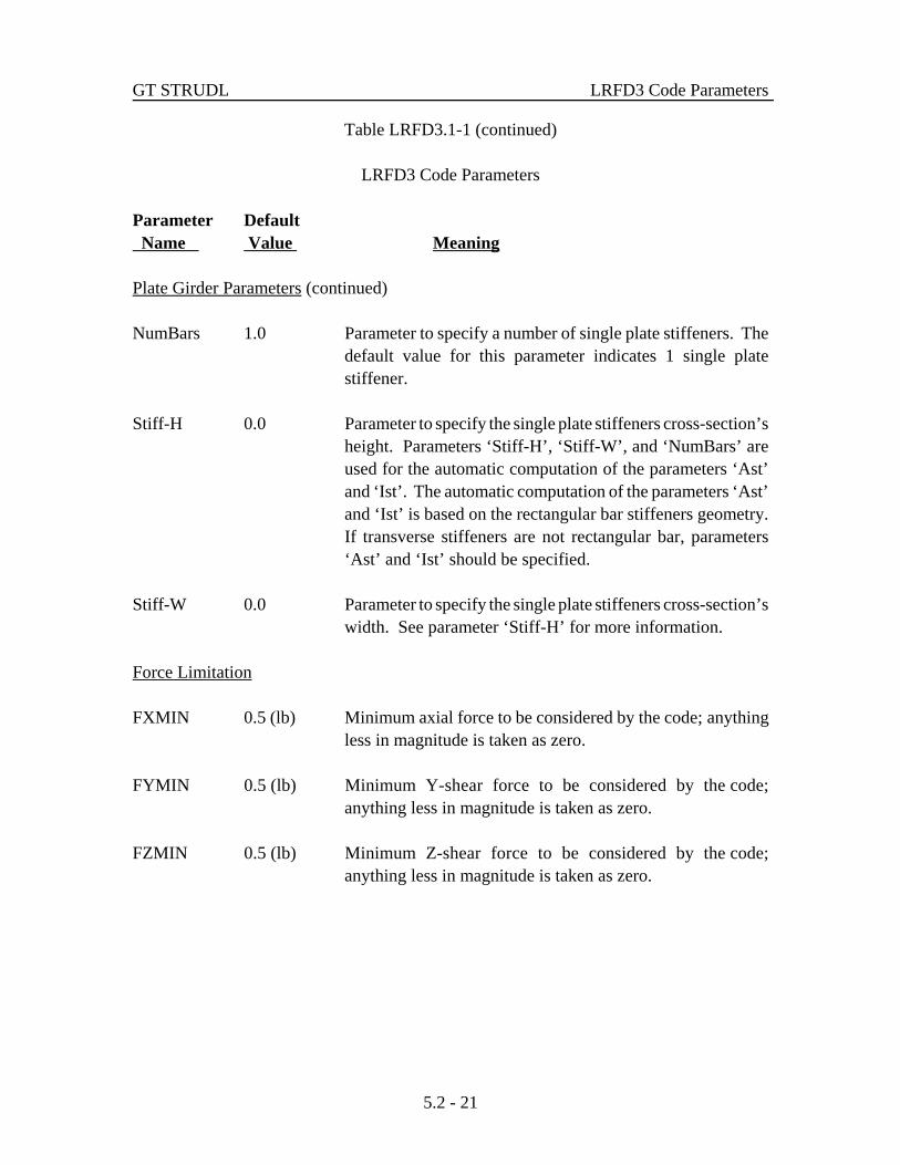
Plate Girder Parameters (continued)
NumBars 1.0 Parameter to specify a number of single plate stiffeners. Thedefault value for this parameter indicates 1 single platestiffener.
Stiff-H 0.0 Parameter to specify the single plate stiffeners cross-section’sheight. Parameters ‘Stiff-H’, ‘Stiff-W’, and ‘NumBars’ areused for the automatic computation of the parameters ‘Ast’and ‘Ist’. The automatic computation of the parameters ‘Ast’and ‘Ist’ is based on the rectangular bar stiffeners geometry.If transverse stiffeners are not rectangular bar, parameters‘Ast’ and ‘Ist’ should be specified.
Stiff-W 0.0 Parameter to specify the single plate stiffeners cross-section’swidth. See parameter ‘Stiff-H’ for more information.
Force Limitation
FXMIN 0.5 (lb) Minimum axial force to be considered by the code; anythingless in magnitude is taken as zero.
FYMIN 0.5 (lb) Minimum Y-shear force to be considered by the code;anything less in magnitude is taken as zero.
FZMIN 0.5 (lb) Minimum Z-shear force to be considered by the code;anything less in magnitude is taken as zero.

LRFD3 Code Parameters GT STRUDL
5.2 - 22
Table LRFD3.1-1 (continued)
LRFD3 Code Parameters
Parameter Default Name Value Meaning
Force Limitation (continued)
MXMIN 20.0 (in-lb) Minimum torsional moment to be considered by the code;anything less in magnitude is taken as zero.
MYMIN 20.0 (in-lb) Minimum Y-bending moment to be considered by the code;anything less in magnitude is taken as zero.
MZMIN 20.0 (in-lb) Minimum Z-bending moment to be considered by the code;anything less in magnitude is taken as zero.
Output Processing and System Parameters
SUMMARY NO Indicates if 'SUMMARY' information is to be saved for themember. Choices are YES or NO; see Sections 2.9 and 7.2of Volume 2A of the User Reference Manual for an expla-nation.
PrintLim NO Parameter to request to print the section limiting values forlimit state and load and resistance factor codes. The defaultoutput from CHECK or SELECT command prints the sectionforce values. A value of ‘YES’ for this parameter indicatesthat the section limiting values should be printed instead ofdefault section forces.

GT STRUDL LRFD3 Code Parameters
5.2 - 23
Table LRFD3.1-1 (continued)
LRFD3 Code Parameters
Parameter Default Name Value Meaning
Output Processing and System Parameters (continued)
TRACE 4.0 Flag indicating when checks of code provisions should beoutput during design or code checking. See Section 7.2 ofVolume 2A of the User Reference Manual for an explanation.
1 = never
2 = on failure
3 = all checks
4 = controlling Actual/Allowable values and sectionforces.
VALUES 1.0 Flag indicating if parameter or property values are to beoutput when retrieved. See Section 7.2 of Volume 2A of theUser Reference Manual for the explanation.
1 = no output
2 = output parameters
3 = output properties
4 = output parameters and properties.

LRFD3 Code Parameters GT STRUDL
5.2 - 24
This page intentionally left blank.

GT STRUDL LRFD3 Steel Design Code and Parameters
5.2 - 25
Table LRFD3.1-2
GTSTRUDL AISC Codes*
Code ParameterName Table Application
LRFD3 LRFD3.1-1 Checks compliance of I shapes, channels, single angles, tees,Volume double angles, round HSS (pipes), rectangular and square 2 - LRFD3 HSS (structural tubes), solid round, square and rectangular
bars, and plate girder profiles to the 1999 AISC LRFD,Third Edition, Specification (96).
ASD9-E ASD9-E.1-1 Checks compliance of I shape profiles to the 1989 AISCVolume ASD Ninth Edition specification (72) with equations that 2 - ASD9-E have been modified to include the modulus of elasticity
(constant E). LRFD2 LRFD2 Checks compliance of I shapes, pipes, structural tubing, plate
Volume 2A girders (subjected to bi-axial bending and axial force),single and double angles (subjected to axial forces only)shape profiles to the 1993 AISC LRFD, Second Edition,Specification (81).
ASD9 ASD9 Checks compliance of I shapes, single angles, channels, tees,Volume 2A double angles, solid round bars, pipes, solid squares and
rectangular bars, and structural tubing shape profiles to the1989 AISC ASD, Ninth Edition, Specification (72).
78AISC 2.2.3.1 Checks compliance of I shapes, single angles, channels, tees,Volume 2B solid round bars, pipes, solid squares and rectangular bars,
and structural tubing (use code name DBLANG for doubleangle) shape profiles to the 1978 AISC Specification (33),Eighth Edition, including 1980 updates.
* For latest (up to date) version of this table, see Table 2.1-1a of Volume 2A.

LRFD3 Steel Design Code and Parameters GT STRUDL
5.2 - 26
Table LRFD3.1-2 (continued)
GTSTRUDL AISC Codes*
Code ParameterName Table Application
69AISC 2.2.3.1 Checks compliance of I shapes, single angles, channels, tees,Volume 2B solid round bars, pipes, solid squares and rectangular bars,
and structural tubing (use code name DBLANG for doubleangle) shape profiles to the 1969 AISC Specification (16),Seventh Edition, including supplements 1, 2, and 3.
W78AISC 2.2.3.1 Similar to 78AISC code, except limited to checking I shapeVolume 2B profiles. This code is identical to the 78AISC code which
was available in older versions of GTSTRUDL (i.e., versionV1M7 and older).
DBLANG 2.2.3.1 Checks compliance of double angle profiles to the 1969 Volume 2B AISC Specification (16), Seventh Edition, including supple-
ments 1, 2, and 3.
W69AISC 2.2.3.1 Similar to 69AISC code, except limited to checking I shapeVolume 2B profiles. This code is identical to the 69AISC code which
was available in older versions of GTSTRUDL (i.e., versionV1M7 and older).
* For latest (up to date) version of this table, see Table 2.1-1a of Volume 2A.

GT STRUDL LRFD3 Steel Design Code and Parameters
5.2 - 27
Table LRFD3.1-3
GTSTRUDL Profile Tables for theDesign based on the LRFD3 Code
Profile Shapes Reference
I shapes See Appendix C of Volume 2A for list of applicable table namesfor I shapes, W, S, M, HP shapes, wide flange shapes, universalbeam shapes, universal column shapes, etc.
Channels See Appendix C of Volume 2A for a list of channel table namesapplicable to LRFD3 codes.
Single Angles See Appendix C of Volume 2A for list of single angle tablenames applicable to LRFD3 code.
Tees See Appendix C of Volume 2A for a list of tee table namesapplicable to LRFD3 codes.
Double Angles See Appendix C of Volume 2A for list of double angle tablenames applicable to LRFD3 code.
Round HSS See Appendix C of Volume 2A for list of round HSS (pipe,circular hollow section) table names applicable to LRFD3 code.
Rectangular HSS See Appendix C of Volume 2A for list of rectangular and squareHSS (structural tube, rectangular and square hollow section) tablenames applicable to LRFD3 code.
Solid Round Bars See Appendix C of Volume 2A for a list of solid round bar tablenames applicable to LRFD3 codes.
Solid Square Bars See Appendix C of Volume 2A for a list of solid square bar tablenames applicable to LRFD3 codes.
Solid Rectangular Bars See Appendix C of Volume 2A for a list of solid rectangular bartable names applicable to LRFD3 codes.
Plate Girders See Appendix C of Volume 2A for a list of plate girder tablenames applicable to LRFD3 codes.

LRFD3 Steel Design Code and Parameters GT STRUDL
5.2 - 28
Table LRFD3.1-4
ASTM Steel Grades and Associated Values of Fy and Fu Based on the1999 AISC LRFD Third Edition Specifications
Applicable Shapes: W, M, S, HP, L, 2L, C, MC, WT, MT, and STshapes from AISC Tables
Steel GradeASTM
DesignationGroup Number Per ASTM A6
Fy, Minimum Yield Stress (ksi)Fu, Minimum Tensile Strength (ksi)
Group 1 Group 2 Group 3 Group 4 Group 5A36 36
583658
3658
3658
3658
A529-G50 5065
5065
NA NA NA
A529-G55 5570
5570
NA NA NA
A572-G42 4260
4260
4260
4260
4260
A572-G50 5065
5065
5065
5065
5065
A572-G55 5570
5570
5570
5570
5570
A572-G60 6075
6075
6075
NA NA
A572-G65 6580
6580
6580
NA NA
A913-G50 5060
5060
5060
5060
5060
A913-G60 6075
6075
6075
6075
6075
A913-G65 6580
6580
6580
6580
6580
A913-G70 7090
7090
7090
7090
7090

GT STRUDL LRFD3 Steel Design Code and Parameters
5.2 - 29
Table LRFD3.1-4 (continued)
ASTM Steel Grades and Associated Values of Fy and Fu Based on the1999 AISC LRFD Third Edition Specifications
Applicable Shapes: W, M, S, HP, L, 2L, C, MC, WT, MT, and ST shapes from AISC Tables
Steel GradeASTM
DesignationGroup Number Per ASTM A6
Fy, Minimum Yield Stress (ksi)Fu, Minimum Tensile Strength (ksi)
Group 1 Group 2 Group 3 Group 4 Group 5A992a 50
655065
5065
5065
5065
A242 5070
5070
46b
67b42a
63a42a
63a
A588 5070
5070
5070
5070
5070
a Applicable to W shapes only.
b Applicable to W and HP shapes only.
NA Indicates that shapes in the corresponding group are not produced for that grade of steel.GTSTRUDL assumes Fy and Fu to be zero in such cases and will not select profiles for thesecombinations of group number and steel grade. Minimum yield stresses (Fy) and minimumtensile strengths (Fu) were obtained from the summary of ASTM specifications included in the1999 AISC LRFD Third Edition specification.

LRFD3 Steel Design Code and Parameters GT STRUDL
5.2 - 30
Table LRFD3.1-5
ASTM Steel Grades and Associated Values of Fy and Fu Based on the1999 AISC LRFD Third Edition Specifications
Applicable Shapes: Round HSS, Steel Pipe, and Rectangular HSS
Steel GradeASTM
DesignationApplicable Shape Series
Fy, Minimum Yield Stress (ksi)Fu, Minimum Tensile Strength (ksi)
Round HSS Steel Pipe Rectangular HSSA53-GB NA 35
60NA
A500-GB 4258
NA 4658
A500-GC 4662
NA 5062
A501 3658
NA 3658
A618-GIA618-GII
Thickness # 3/4
5070 NA
5070
A618-GIA618-GII
Thickness > 3/4
4667 NA
4667
A618GIII 5065
NA 5065
A242-G46 NA NA 4667
A242-G50 NA NA 5070
A588 NA NA 5070
A847 5070
NA 5070
NA Not applicable. See Table LRFD3.1-4 for more explanation.

GT STRUDL 00BS5950 Design Code and Parameters
5.2 - 31
5.2.2 BS5950 Design Code and Parameters
00BS5950 CodeBritish StandardBS 5950-1:2000
00BS5950.1.2 00BS5950 Code
The 00BS5950 code of GTSTRUDL may be used to select or check any of the followingshapes:
I shapes Subjected to bending and axial forceSingle Angles Subjected to axial force onlyCircular Hollow Sections (Pipes) Subjected to bending and axial force
The term I shapes is used to mean rolled or welded I and H beams and columns, universalbeams and columns, joists, universal bearing piles, W, S, M, and HP profiles with doublysymmetric cross-sections.
The code is based on the BS 5950-1:2000 "British Standard Structural use of steelwork inbuilding, Part 1: Code of practice for design rolled and welded sections" amendment number13199, issued May 2001. The 00BS5950 code utilizes the limit state design techniques of theBSI (British Standard Institution) specification.
The following assumptions are made throughout the 00BS5950 code.
1. Torsional stresses are usually small when compared to axial and bending stresses,and may be neglected. No checks are made for torsion. The designer is remindedto check the torsional stresses whenever they become significant.
2. Web stiffeners are considered for web shear stress, but they are not designed.

Design Prerelease Features GT STRUDL
5.2 - 32
Figure 00BS5950.1-1 Local Axes for Design with 00BS5950

GT STRUDL 00BS5950 Design Code and Parameters
5.2 - 33
The sections of the BS 5950-1:2000 specifications (95) that are considered by theGTSTRUDL 00BS5950 code are summarized below:
Section Title
3. Properties of materials and section properties3.5 Classification of cross-sections3.5.1 General3.5.2 Classification3.5.3 Flanges of compound I- or H-sections
Table 11. Limiting width-to-thickness ratios for sections otherthan CHS and RHS
3.5.5 Stress ratios for classification3.5.6.2 I- or H-sections with equal flanges3.5.6.4 Circular hollow sections3.6.2.2 Effective area3.6.2.3 Effective modulus when web is fully effective3.6.4 Equal-leg angle sections3.6.5 Alternative method3.6.6 Circular hollow sections
4. Design of structural members4.2.3 Shear capacity
4.2.5 Moment capacity4.2.5.2 Low shear4.2.5.3 High shear
4.3 Lateral-torsional buckling4.3.4 Destabilizing load.4.3.5 Effective length for lateral-torsional buckling
Table 13. Effective length LE for beams without intermediaterestraint
4.3.6.2 I-, H-, channel and box sections with equal flanges4.3.6.4 Buckling resistance moment4.3.6.5 Bending strength pb4.3.6.6 Equivalent uniform moment factor mLT
Table 18. Equivalent uniform moment factor mLT for lateral-torsional buckling

Design Prerelease Features GT STRUDL
5.2 - 34
Section Title
4.3.6.9 Ratio $W
4.4.5 Shear buckling resistance4.4.5.2 Simplified method4.4.5.3 More exact method
4.6 Tension members4.6.1 Tension capacity4.7.2 Slenderness
4.7 Compression members4.7.2 Slenderness4.7.4 Compression resistance4.7.5 Compressive strength
Table 23. Allocation of strut curve
4.8 Members with combined moment and axial force4.8.2 Tension members with moments4.8.2.2 Simplified method4.8.2.3 More exact method
4.8.3 Compression members with moments4.8.3.2 Cross-section capacity
4.8.3.3 Member buckling resistance4.8.3.3.1 Simplified method
Table 26. Equivalent uniform moment factor m for flexuralbuckling
4.8.3.3.2 More exact method for I- or H-sections with equal flangesTable 26. Equivalent uniform moment factor m for flexural
buckling4.8.3.3.3 More exact method for CHS, RHS or box sections with equal flanges
Table 26. Equivalent uniform moment factor m for flexuralbuckling
4.9 Members with biaxial moments

GT STRUDL 00BS5950 Design Code and Parameters
5.2 - 35
Section Title
Annex B (normative)Lateral-torsional buckling of members subject to bending
B.2 Buckling resistanceB.2.1 Bending strength.B.2.2 Perry factor and Robertson constantB.2.3 Uniform I, H and channel sections with equal flanges
Annex C (normative)Compressive strength
C.1 Strut formulaC.2 Perry factor and Robertson constant
Annex H (normative)Web buckling resistance
H.1 Shear buckling strength
Annex I (normative)Combined axial compression and bending
I.2 Reduced plastic moment capacityI.2.1 I- or H-section with equal flanges
Tensile or compressive axial stresses, bi-axial bending, shear stresses, and combinedstresses are considered for all cross-sections except single angles (tension or compression axialstresses only). Provisions for columns in simple construction are included. Parameters allowingfor the changes which occur in structural steel at high temperatures have been included and maybe invoked at the user's discretion.
The detailed explanation of the code parameters, cross-section properties, generalnomenclature, and code equations are as follows.
1. Table 00BS5950.1-1 Shows the parameters used by 00BS5950 code. Table00BS5950.1-1 contains the applicable parameternames, their default values, and a brief description ofthe parameters.
2. Section 00BS5950.2 Describes the cross-section properties used for eachshape.
Design Prerelease Features GT STRUDL
5.2 - 36
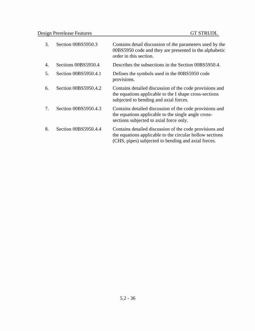
3. Section 00BS5950.3 Contains detail discussion of the parameters used by the00BS5950 code and they are presented in the alphabeticorder in this section.
4. Sections 00BS5950.4 Describes the subsections in the Section 00BS5950.4.
5. Section 00BS5950.4.1 Defines the symbols used in the 00BS5950 codeprovisions.
6. Section 00BS5950.4.2 Contains detailed discussion of the code provisions andthe equations applicable to the I shape cross-sectionssubjected to bending and axial forces.
7. Section 00BS5950.4.3 Contains detailed discussion of the code provisions andthe equations applicable to the single angle cross-sections subjected to axial force only.
8. Section 00BS5950.4.4 Contains detailed discussion of the code provisions andthe equations applicable to the circular hollow sections(CHS, pipes) subjected to bending and axial forces.

GT STRUDL 00BS5950 Design Code and Parameters
5.2 - 37
Table 00BS5950.1-100BS5950 Code Parameters
Parameter Default Name Value Meaning
CODE Required Identifies the code to be used for member checking or memberselection. Specify 00BS5950 for code name. See Sections00BS5950.2, 00BS5950.3, and 00BS5950.4 for a more detaileddescription.
TBLNAM UNIBEAMS Identifies the table of profiles to be used during selection(SELECT command). See Table 00BS5950.1-2 for choices.
METHOD EXACT Identifies the design method. This parameter indicates the typeof method that should be used for the shear or combinedcapacity checks.
BOTH = Use simplified and the more exact methods. See Sections 4.4.5, 4.8.2 and 4.8.3 of BS5950-1:2000 (95).
EXACT = Use the more exact method. See Sections 4.4.5.3, 4.8.2.3, 4.8.3.3.2, and 4.8.3.3.3 of BS5950-1:2000 (95).
SIMPLIFY = Use simplified method. See Sections 4.4.5.2,4.8.2.2 and 4.8.3.2 of BS 5950-1:2000 (95).
SECTYPE ROLLED Indicates that the cross-section is rolled or welded shape. Thisparameter is used to determine the equations that are applicableto the rolled or welded shape.
ROLLED = Member is hot rolled.
WELDED = Member is welded/coldformed.

Design Prerelease Features GT STRUDL
5.2 - 38
Table 00BS5950.1-1 (continued)
00BS5950 Code Parameters
Parameter Default Name Value Meaning
SHRAREAF Computed SHeaR AREA Factor is used for the computation of the sheararea. When an alternate value other than COMPUTE orTABLE is specified, shear area is computed as theSHRAREAF times the cross sectional area (AV = AY =SHRAREAF × AX).
COMPUTE = Compute the shear area based on the Section4.2.3 of BS 5950-1:2000 (95) except forsingle and double angles. Shear area forsingle and double angles are extracted fromGTSTRUDL or USER table.
TABLE = Shear area from GTSTRUDL or USER tableis used.
a 254000.0(mm) Distance between web stiffeners. This parameter is used tocompute a/d ratio. a/d is the ratio of the distance betweenstiffeners to web depth. An arbitrary high value of 254000.0(mm) has been assumed as a default to indicate that the webstiffeners are absent. A value is necessary to account for webstiffeners in the shear capacity calculation (Provisions '4.4.5.2'and '4.4.5.3').
SimpSupp NO Indicates that if a member is simply supported or not. Thisparameter is used to determine the equations that are applicableto the simply supported members (Provisions ‘4.2.5.2Z’,‘4.2.5.3Z’, ‘4.2.5.2Y’, and ‘4.2.5.3Y’.
NO = Member is not simply supported.
YES = Member is simply supported.
CODETOL 0.0 Percent variance from 1.0 for compliance with the provisionsof a code. The ratio of actual/limiting must be less than orequal to [1.0 + CODETOL/100].

GT STRUDL 00BS5950 Design Code and Parameters
5.2 - 39
Table 00BS5950.1-1 (continued)
00BS5950 Code Parameters
Parameter Default Name Value Meaning
PF 1.0 Area reduction factor for holesout in members subject to axialtension.
Material Properties
STEELGRD S235JRG2 Identifies the grade of steel from which a member is made. See Table 00BS5950.1-3 for STEEL GRaDes and theirproperties.
Py Computed Design strength py (yield stress) of member. Computed fromparameter STEELGRD if not given.
REDPy 1.0 Reduction factor for parameter Py. This factor times parameterPy gives the design strength (py) value used by the code. Usedto account for property changes at high temperatures.
Pyf Py Design strength of the flange. If not specified, it is assumedequal to the parameter Py. This parameter is used to define ahybrid cross-section, see parameter Pyw also.
Pyw Py Design strength of the web. If not specified, it is assumedequal to the parameter Py. This parameter is used to define ahybrid cross-section, see parameter Pyf also.
REDE 1.0 Reduction factor for E, the modulus of elasticity. Similar toREDPy.

Design Prerelease Features GT STRUDL
5.2 - 40
Table 00BS5950.1-1 (continued)
00BS5950 Code Parameters
Parameter Default Name Value Meaning
Slenderness Ratio
SLENCOMP Computed Maximum permissible slenderness ratio (LE/r, KL/r) for amember subjected to axial compression. The default value formaximum compression slenderness ratio is equal to 180.
SLENTEN Computed Maximum permissible slenderness ratio (L/r) for a membersubjected to axial tension. Only a user-specified value willinitiate the slenderness ratio check for a tension member.
Effective Length for a Compression Member
EFLEY 1.0 Effective factor value used for the computation of nominaleffective length, LEy = EFLEY × LY for a compressionmember. Nominal effective length, LEY, is used in thecomputation of maximum slenderness ratio about the local Yaxis of the profile. See Table 00BS5950.1-4 or Sections 4.7.2,4.7.3, and Table 22 of BS 5950-1:2000 (95) for the EFLEYvalues.
LY Computed Unbraced length for buckling about the local Y axis of thecross-section. This parameter is used to compute nominaleffective length LEy for a compression member (LEy = EFLEY× LY). The default value is computed as a length of the mem-ber.
FRLY 1.0 Fractional form of the parameter LY, allows unbraced length tobe specified as fractions of the total length. Used only whendefault value of ‘Computed’ is used for parameter LY (LY =FRLY × Member Length).

GT STRUDL 00BS5950 Design Code and Parameters
5.2 - 41
Table 00BS5950.1-1 (continued)
00BS5950 Code Parameters
Parameter Default Name Value Meaning
Effective Length for a Compression Member (continued)
EFLEZ 1.0 Effective factor value used for the computation of nominal effec-tive length, LEz = EFLEZ × LZ for a compression member. Nominal effective length, LEZ, is used in the computation ofmaximum slenderness ratio about the local Z axis of the profile. See Table 00BS5950.1-4 or Sections 4.7.2, 4.7.3, and Table 22 ofBS 5950-1:2000 (95) for the EFLEZ values.
LZ Computed Unbraced length for buckling about the local Z axis of the cross-section. This parameter is used to compute nominal effectivelength LEz for a compression member (LEz = EFLEZ × LZ). Thedefault value is computed as a length of the member.
FRLZ 1.0 Fractional form of the parameter LZ, allows unbraced length to bespecified as fractions of the total length. Used only when defaultvalue of ‘Computed’ is used for parameter LZ (LZ = FRLZ ×Member Length).
Effective Length for Lateral-Torsional Buckling
LE LLT Effective length of a member for lateral torsional buckling of abeam with restraints at the ends. Default value is the effectivelength between restraints against lateral-torsional buckling of amember under bending, see parameter LLT (LE = EFLE × LLT). See Table 00BS5950.1-5 for alternative values and also see Table13 and 14 of the BS5950-1:2000 (95).

Design Prerelease Features GT STRUDL
5.2 - 42
Table 00BS5950.1-1 (continued)
00BS5950 Code Parameters
Parameter Default Name Value Meaning
Effective Length for Lateral-Torsional Buckling (continued)
EFLE 1.0 Effective factor value used for the computation of the effectivelength, LE of a member under bending. Used only when defaultvalue of LLT is used for parameter LE (LE = EFLE × LLT, seeTable 00BS5950.1-5 and parameter LE).
LLT Computed Segment length between restraints against lateral-torsionalbuckling (unbraced length). This parameter generally used tospecify the segment length of the compression flange restraintagainst lateral-torsional buckling (unbraced length of thecompression flange). Computed as length of member.
FRLLT 1.0 Fractional value used for the computation of the unbraced lateral-torsional buckling length of a member, LLT. Used only whendefault value of ‘Computed’ is used for parameter LLT (LLT =FRLLT × Member Length).
Equivalent Uniform Moment Factors
mLT Computed Equivalent uniform moment factor for lateral-torsional buckling(mLT), which is used in the member buckling resistance equations. This parameter modifies Z axis bending buckling capacity incombined axial and bending capacity equations. See Section00BS5950.3 for more explanation.
my Computed Equivalent uniform moment factor for flexural buckling (my),which is used in the member buckling resistance equations. Thisparameter modifies Y axis bending capacity in combined axialand bending capacity equations. See Section 00BS5950.3 formore explanation.

GT STRUDL 00BS5950 Design Code and Parameters
5.2 - 43
Table 00BS5950.1-1 (continued)
00BS5950 Code Parameters
Parameter Default Name Value Meaning
Equivalent Uniform Moment Factors (continued)
mz Computed Equivalent uniform moment factor for flexural buckling (mz),which is used in the member buckling resistance equations. Thisparameter modifies Z axis bending capacity in combined axialand bending capacity equations. See Section 00BS5950.3 formore explanation.
myz Computed Equivalent uniform moment factor for lateral flexural buckling(myz), which is used in the member out-of-plane bucklingresistance equations. This parameter modifies Y axis bendingcapacity in combined axial and bending capacity equations. SeeSection 00BS5950.3 for more explanation.
SDSWAYY YES Indicates the presence or absence of SiDeSWAY about the localY axis.
YES = Sidesway permitted.
NO = Sidesway prevented.
SDSWAYZ YES Indicates the presence or absence of SiDeSWAY about the localZ axis.
YES = Sidesway permitted.
NO = Sidesway prevented.

Design Prerelease Features GT STRUDL
5.2 - 44
Table 00BS5950.1-1 (continued)
00BS5950 Code Parameters
Parameter Default Name Value Meaning
Equivalent Uniform Moment Factors (continued)
DESTLDY YES Indicates the presence or absence of a DESTabilizing LoaDwhich causes movement in the member local Y axis direction(and possibly rotation about the member local Y axis). Destabi-lizing load conditions exist when a load is applied in the local Zaxis direction of a member and both the load and the member arefree to deflect laterally (and possibly rotationally also) relative tothe centroid of the member. This parameter is only applicable toLOADS list or ALL LOADS of the PARAMETERS command.
YES = Destabilizing load.
NO = Normal load.
DESTLDZ YES Indicates the presence or absence of a DESTabilizing LoaDwhich causes movement in the member local Z axis direction(and possibly rotation about the member local Z axis). Destabi-lizing load conditions exist when a load is applied to the topflange (local Y axis load) of a member and both the load and theflange are free to deflect laterally (and possibly rotationally also)relative to the centroid of the member. This parameter is onlyapplicable to LOADS list or ALL LOADS of the PARAMETERScommand.
YES = Destabilizing load.
NO = Normal load.
Force Limitation
FXMIN 2.224 (N) Minimum axial force to be considered by the code; anything lessin magnitude is taken as zero. Units are in newtons (N).
FYMIN 2.224 (N) Minimum Y-shear force to be considered by the code; anythingless in magnitude is taken as zero.

GT STRUDL 00BS5950 Design Code and Parameters
5.2 - 45
Table 00BS5950.1-1 (continued)
00BS5950 Code Parameters
Parameter Default Name Value Meaning
Force Limitation (continued)
FZMIN 2.224 (N) Minimum Z-shear force to be considered by the code; anythingless in magnitude is taken as zero.
MYMIN 2260.0 Minimum Y-bending moment to be considered by the(mm-N) code; anything less in magnitude is taken as zero.
MZMIN 2260.0 Minimum Z-bending moment to be considered by the(mm-N) code; anything less in magnitude is taken as zero.
Output Processing
MXTRIALS 500.0 Maximum number of profiles to be tried when designing amember. Default is larger than the number of profiles in mosttables.
SUMMARY NO Indicates if 'SUMMARY' information is to be saved for themember. Choices are YES or NO; see Sections 2.9 and 7.2 ofVolume 2A of the User Reference Manual for an explanation
PrintLim NO Parameter to request to print the section limiting values for limitstate and load and resistance factor codes. This parameter isapplicable to the steel design CHECK and SELECT commands. The default output from CHECK or SELECT command prints thesection force values. A value of ‘YES’ for this parameterindicates that the section limiting values should be printed insteadof default section forces.

Design Prerelease Features GT STRUDL
5.2 - 46
Table 00BS5950.1-1 (continued)
00BS5950 Code Parameters
Parameter Default Name Value Meaning
Output Processing (continued)
TRACE 4.0 Flag indication when checks of code provisions should be outputduring design or code checking. See Section 7.2 of Volume 2A ofthe User Reference Manual for the explanation.
1 = never
2 = on failure
3 = all checks
4 = controlling Actual/Allowable values and section forces.
VALUES 1.0 Flag indication if parameter or property values are to be outputwhen retrieved. See Section 7.2 of Volume 2A of the UserReference Manual for the explanation.
1 = no output
2 = output parameters
3 = output properties
4 = output parameters and properties.

GT STRUDL 00BS5950 Design Code and Parameters
5.2 - 47
Table 00BS5950.1-2GTSTRUDL Profile Tables for the
Design based on the 00BS5950 Code
Profile Shapes Reference
I shapes See Appendix C of Volume 2A for list of Applicable Tablenames for universal beams, universal columns, joists, universalbearing piles, I shapes, W, S, M, HP shapes, wide flangeshapes, etc.
Single Angles See Appendix C of Volume 2A for list of single angle tablenames applicable to 00BS5950 code.
Circular Hollow Sections See Appendix C of Volume 2A for list of circular hollowsection (pipe, round HSS) table names applicable to 00BS5950code.

Design Prerelease Features GT STRUDL
5.2 - 48
Table 00BS5950.1-3
Steel Grades Based on the BS 5950-1:2000 (00BS5950) and 1993 Eurocode (EC3) Specification
Steel GradeNominal Yield Strength, fy (N/mm2) Ultimate Tensile Strength, fu
t # 16 16< t #40 40< t #63 63< t #80 80< t #100 100< t #150 150< t #200 200< t #250 t # 100 100< t #150 150< t #250
S185 185 175 ! ! ! ! ! ! 290 ! !
S235JR 235 225 ! ! ! ! ! ! 340 ! !
S235JRG1 235 225 ! ! ! ! ! ! 340 ! !
S235JRG2 235 225 215 215 215 195 185 175 340 340 320
S235J0 235 225 215 215 215 195 185 175 340 340 320
S235J2G3 235 225 215 215 215 195 185 175 340 340 320
S235J2G4 235 225 215 215 215 195 185 175 340 340 320
S275JR 275 265 255 245 235 225 215 205 410 400 380
S275J0 275 265 255 245 235 225 215 205 410 400 380
S275J2G3 275 265 255 245 235 225 215 205 410 400 380
S275J2G4 275 265 255 245 235 225 215 205 410 400 380
S275N 275 265 255 245 235 225 ! ! 370 350 !
S275NL 275 265 255 245 235 225 ! ! 370 350 !

GT STRUDL 00BS5950 Code and Parameters
5.2 - 49
Table 00BS5950.1-3 (continued)
Steel Grades Based on the BS 5950-1:2000 (00BS5950) and 1993 Eurocode (EC3) Specification
Steel GradeNominal Yield Strength, fy (N/mm2) Ultimate Tensile Strength, fu
t # 16 16< t #40 40< t #63 63< t #80 80< t #100 100< t #150 150< t #200 200< t #250 t # 100 100< t #150 150< t #250
S355JR 355 345 335 325 315 295 285 275 490 470 450
S355J0 355 345 335 325 315 295 285 275 490 470 450
S355J2G3 355 345 335 325 315 295 285 275 490 470 450
S355J2G4 355 345 335 325 315 295 285 275 490 470 450
S355K2G3 355 345 335 325 315 295 285 275 490 470 450
S355K2G4 355 345 335 325 315 295 285 275 490 470 450
S355N 355 345 335 325 315 295 ! ! 470 450 !
S355NL 355 345 335 325 315 295 ! ! 470 450 !
S420N 420 400 390 370 360 340 ! ! 520 500 !
S420NL 420 400 390 370 360 340 ! ! 520 500 !
S460N 460 440 430 410 400 ! ! ! 550 ! !
S460NL 460 440 430 410 400 ! ! ! 550 ! !

Design Prerelease Features GT STRUDL
5.2 - 50
Table 00BS5950.1-4Effective Factor Values EFLEY and EFLEZ for
Nominal Effective Length LEy and LEz computationBritish Standard BS 5950-1:2000 Specification
a) non-sway mode*
Restraint (in the plane under consideration) by other parts of structure EFLEYand
EFLEZEffectively held inposition at both ends
Effectively restrained in direction at both ends 0.7Partially restrained in direction at both ends 0.85Restrained in direction at one end 0.85Not restrained in direction at either end 1.0
b) sway mode*
One end Other end EFLEYand
EFLEZEffectively held inposition and restrainedin direction
Not held inposition
Effectively restrained in direction 1.2Partially restrained in direction 1.5Not restrained in direction 2.0
* Excluding angle, channel or T-section struts designed in accordance with Section4.7.10 of the BS 5950-1:2000 (95)
Example:PARAMETERS
'EFLEY' 1.5 MEMBER 1 $ LEy = 1.5LY for member 1'EFLEZ' 1.2 MEMBER 25 $ LEz = 1.2LZ for member 25
LY and LZ are the unbraced length for buckling about the local Y and Z axis of thecross-section (see parameter LY and LZ).

GT STRUDL 00BS5950 Code and Parameters
5.2 - 51
Table 00BS5950.1-5Effective Length LE
British Standard BS 5950-1:2000 SpecificationConditions of restraint at supports Alternate values for
Parameter LELoading conditions
Normal
DESTLDZ = NO
Destabilizing
DESTLDZ = YES
Default value for parameter LE LLT EFLLT×LLT EFLLT×LLT
Compression flange laterally restrained. Nominal torsional restraint against rotation about longitudinal axis.
Both flanges fully restrained againstrotation on plan
A1 0.7LLT 0.85LLT
Compression flange fully restrainedagainst rotation on plan
A2 0.75LLT 0.9LLT
Both flanges partially restrained againstrotation on plan
A3 0.8LLT 0.95LLT
Compression flange partially restrainedagainst rotation on plan
A4 0.85LLT 1.0LLT
Both flanges free to rotate on plan A5 1.0LLT 1.2LLT
Compression flange laterally unrestrained. Both flanges free to rotate on plan
Partial torsional restraint against rotationabout longitudinal axis provided byconnection of bottom flange to supports
A6 1.0LLT + 2D 1.2LLT + 2D
Partial torsional restraint against rotationabout longitudinal axis provided only bypressure of bottom flange onto supports
A7 1.2LLT + 2D 1.4LLT + 2D
Example:PARAMETERS
'DESTLDZ' 'NO' LOAD 2'DESTLDZ' 'YES' LOAD 5'LE' 'A3' MEMBER 1 $ LE = 0.8LLT for load 2 and
$ LE = 0.95LLT for load 5'LE' 'A7' MEMBER 8 $ LE = 1.2LLT+2D for load 2 and
$ LE = 1.4LLT+2D for load 5
1. D is the depth of cross-section (table property YD).2. Default value for parameter EFLLT is equal to 1.0.3. For cantilevers and other types of beams not in Table 00BS5950.1-6, use parameter EFLLT to specify the effective
length factor (LE = EFLLT×LLT).

Design Prerelease Features GT STRUDL
5.2 - 52
This page intentionally left blank.

GT STRUDL GTSTRUDL Indian Standard Design Code IS800
5.2 - 53
5.2.3 GTSTRUDL Indian Standard Design Code IS800
A new steel design code named IS800 has been added.
IS800 CodeIndian Standard
IS:800-1984
IS800.1.2 IS800 Code
The IS800 code of GTSTRUDL may be used to select or check any of the followingshapes:
I shapes Round BarsChannels PipesSingle angles Square Bars Tees Rectangular BarsDouble angles Structural Tubing
The term I shapes is used to mean ROLLED I beams and columns, universal beams andcolumns, W, S, M, and HP profiles with doubly symmetric cross-sections.
The code is based on the Indian Standard “Code of Practice for General Construction inSteel (Second Revision)” adopted April 25, 1984 (Twelfth Reprint December 1995,incorporating Amendments No. 1 and 2), IS:800-1984. The IS800 code utilizes the allowablestress design techniques of the Indian Standard IS:800-1984 code.
Design criteria for the above shapes are presented in Section IS800.4. A detaileddiscussion is presented on the allowable stresses for each of these shapes in Sections IS800.5.2through IS800.5.10.
The following assumptions are made throughout the IS800 code.
1. The member under consideration is made of one grade of steel.
2. The modulus of elasticity of the steel is 200,000 MPa. This is of particularimportance, since the computation of several constants appearing in the equationsof the IS:800-1984 Specification (92) is based on this value.
3. Torsional stresses are usually small when compared to axial and bending stresses,and may be neglected. No checks are made for torsion. The designer is remindedto check the torsional stresses whenever they become significant.

Design Prerelease Features GT STRUDL
5.2 - 54
Figure IS800.1-1 Assumed Local Axes Direction for Hot Rolled Shapes

GT STRUDL GTSTRUDL Indian Standard Design Code IS800
5.2 - 55
Figure IS800.1-1 (continued) Assumed Local Axes Direction for Hot Rolled Shapes

Design Prerelease Features GT STRUDL
5.2 - 56
Figure IS800.1-1 (continued) Assumed Local Axes Direction for Hot Rolled Shapes
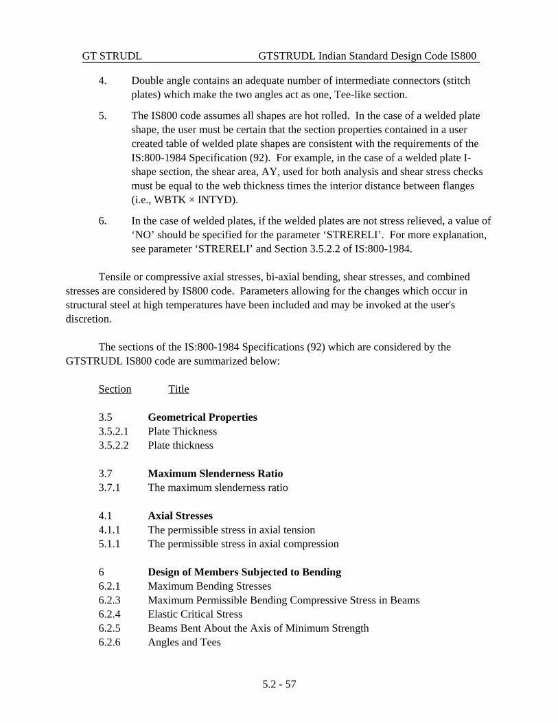
GT STRUDL GTSTRUDL Indian Standard Design Code IS800
5.2 - 57
4. Double angle contains an adequate number of intermediate connectors (stitchplates) which make the two angles act as one, Tee-like section.
5. The IS800 code assumes all shapes are hot rolled. In the case of a welded plateshape, the user must be certain that the section properties contained in a usercreated table of welded plate shapes are consistent with the requirements of theIS:800-1984 Specification (92). For example, in the case of a welded plate I-shape section, the shear area, AY, used for both analysis and shear stress checksmust be equal to the web thickness times the interior distance between flanges(i.e., WBTK × INTYD).
6. In the case of welded plates, if the welded plates are not stress relieved, a value of‘NO’ should be specified for the parameter ‘STRERELI’. For more explanation, see parameter ‘STRERELI’ and Section 3.5.2.2 of IS:800-1984.
Tensile or compressive axial stresses, bi-axial bending, shear stresses, and combinedstresses are considered by IS800 code. Parameters allowing for the changes which occur instructural steel at high temperatures have been included and may be invoked at the user'sdiscretion.
The sections of the IS:800-1984 Specifications (92) which are considered by theGTSTRUDL IS800 code are summarized below:
Section Title
3.5 Geometrical Properties3.5.2.1 Plate Thickness3.5.2.2 Plate thickness
3.7 Maximum Slenderness Ratio3.7.1 The maximum slenderness ratio
4.1 Axial Stresses4.1.1 The permissible stress in axial tension5.1.1 The permissible stress in axial compression
6 Design of Members Subjected to Bending6.2.1 Maximum Bending Stresses6.2.3 Maximum Permissible Bending Compressive Stress in Beams6.2.4 Elastic Critical Stress6.2.5 Beams Bent About the Axis of Minimum Strength6.2.6 Angles and Tees

Design Prerelease Features GT STRUDL
5.2 - 58
6.4 Shear Stresses6.4.1 Maximum Shear Stress6.4.2 Average Shear Stress6.2.4 Elastic Critical Stress6.2.5 Beams Bent About the Axis of Minimum Strength
7.1 Combined of Direct Stresses7.1.1 Combined Axial Compression and Bending7.1.2 Combined Axial Tension and Bending7.1.3 Symbols7.1.4 Bending and Shear
The detailed explanation of the code parameters, cross-section properties, generalnomenclature, and code equations are as follows.
1. Table IS800.1-1 Shows the parameters used by the IS800 code. TableIS800.1-1 contains the applicable parameter names, theirdefault values, and a brief description of the parameters.
2. Section IS800.2 Describes the cross-section properties used for each shape.
3. Section IS800.3 Contains detail discussion of the parameters used by theIS800 code and they are presented in alphabetic order inthis section.
4. Section IS800.4 Describes the subsections in the Section IS800.4.
5. Section IS800.4.1 Defines the symbols used in the IS800 code provisions.
6. Section IS800.4.2 Contains detailed discussion of the code provisions and theequations applicable to the I shape cross-sections subjectedto bending and axial forces.
7. Section IS800.4.3 Contains detailed discussion of the code provisions and theequations applicable to the Channel cross-sectionssubjected to bending and axial forces.
8. Section IS800.4.4 Contains detailed discussion of the code provisions and theequations applicable to the Single Angle cross-sectionssubjected to bending and axial forces

GT STRUDL GTSTRUDL Indian Standard Design Code IS800
5.2 - 59
9. Section IS800.4.5 Contains detailed discussion of the code provisions and theequations applicable to the Tee cross-sections subjected tobending and axial forces.
10. Section IS800.4.6 Contains detailed discussion of the code provisions and theequations applicable to the Double Angle cross-sectionssubjected to bending and axial forces.
11. Section IS800.4.7 Contains detailed discussion of the code provisions and theequations applicable to the Round Bar cross-sectionssubjected to bending and axial forces.
12. Section IS800.4.8 Contains detailed discussion of the code provisions and theequations applicable to the Pipe cross-sections subjected tobending and axial forces.
13. Section IS800.4.9 Contains detailed discussion of the code provisions and theequations applicable to the Square and Rectangular Barcross-sections subjected to bending and axial forces.
14. Section IS800.4.10 Contains detailed discussion of the code provisions and theequations applicable to the Structural Tubing cross-sectionssubjected to bending and axial forces.

Design Prerelease Features GT STRUDL
5.2 - 60
This page intentionally left blank.

GT STRUDL GTSTRUDL Indian Standard Design Code IS800
5.2 - 61
Table IS800.1-1
IS800 Code Parameters
Parameter Default Name Value Meaning
CODE Required Identifies the code to be used for member checking or memberselection. Specify IS800 for code name. See Table IS800.1-2 andSections IS800.2, IS800.3, and IS800.4 for a more detaileddescription.
TBLNAM ISBEAMS Identifies the table of profiles to be used during selection(SELECT command). See Table IS800.1-3 for choices.
CODETOL 0.0 Percent variance from 1.0 for compliance with the provisions of acode. The ratio of Actual/Allowable must be less than or equal to[1.0 + CODETOL/100].
PF 1.0 Area reduction factor for holesout in members subject to axialtension.
a 254000.0 Distance between web stiffeners. This parameter is used to(mm) compute a/h ratio. The a/h ratio is the ratio of the distance
between stiffeners to the web depth. An arbitrary high value of254000.0 (mm) has been assumed as a default to indicate that webstiffeners are absent. A value is necessary to account for webstiffeners in the allowable shear stress calculation (Provision ‘6.4.2Y’ and ‘6.4.2 Z’).
STRERELI YES Parameter to specify if the welded plates are stress relieved or not. This parameter is used for the computationof the effective cleardepth of the web (see Section 3.5.2.2 of IS:800-1984 and SectionIS800.4.2 of Volume 2 - IS800). A value of NO indicates thatwhen the effective clear depth of the web is being computed,assume that the welded plates are not stress relieved. The defaultvalue of ‘YES’ indicates that the cross-section is stress relieved.

Design Prerelease Features GT STRUDL
5.2 - 62
Table IS800.1-1 (continued)
IS800 Code Parameters
Parameter Default Name Value Meaning
Material Properties
STEELGRD A36 Identifies the grade of steel from which a member is made. SeeTable IS800.1-4 for steel grades and their properties.
FY Computed Yield stress of member. Computed from STEELGRD if not given.
REDFY 1.0 Reduction factor for FY. This factor times FY gives the fy valueused by the code. Used to account for property changes at hightemperatures.
REDE 1.0 Reduction factor for E, the modulus of elasticity. Similar toREDFY.
Slenderness Ratio
SLENCOMP Computed Maximum permissible slenderness ratio (KL/r) for membersubjected to axial compression. When no value is specified forthis parameter, the value of 180 is used for the maximumslenderness ratio.
SLENTEN Computed Maximum permissible slenderness ratio (L/r) for membersubjected to axial tension. When no value is specified for thisparameter, the value of 400 is used for the maximum slendernessratio.
K-Factors
COMPK NO Parameter to request the computation of the effective length factorsKY and KZ (Section 2.2 of Volume 2A).
YES = Compute KY and KZ factors.
KY = Compute KY only.
KZ = Compute KZ only.
NO = Use default or specified values for KY and KZ.

GT STRUDL GTSTRUDL Indian Standard Design Code IS800
5.2 - 63
Table IS800.1-1 (continued)
IS800 Code Parameters
Parameter Default Name Value Meaning
K-Factors (continued)
KY 1.0 Effective length factor for buckling about the local Y axis of theprofile. See Section 2.2 of Volume 2A for GTSTRUDL computa-tion of effective length factor, KY.
KZ 1.0 Effective length factor for buckling about the local Z axis of theprofile. See Section 2.2 of Volume 2A for GTSTRUDL computa-tion of effective length factor, KZ.
Print-K YES Parameter to print the computed K-factor values after the defaultcode check or select command output (TRACE 4 output). Thedefault value of ‘YES’ for this parameter indicates that thecomputed K-factor values should be printed after the code check orselect command output. The column names attached to the startand end of the code checked member is also printed. This printedinformation allows the user to inspect the automatic detection ofthe columns attached to the start and end of the designed member. A value of ‘NO’ indicates that K-factor values and the names ofthe attached columns to the start and end of the designed membershould not be printed.
SDSWAYY YES Indicates the presence or absence of sidesway about the local Yaxis.
YES = sidesway permitted.
NO = sidesway prevented.
SDSWAYZ YES Indicates the presence or absence of sidesway about the local Zaxis.
YES = sidesway permitted.
NO = sidesway prevented.

Design Prerelease Features GT STRUDL
5.2 - 64
Table IS800.1-1 (continued)
IS800 Code Parameters
Parameter Default Name Value Meaning
CantiMem NO Parameter to indicate that a member or a physical member which ispart of a cantilever truss should be considered as a cantilever in theK-factor computation. True cantilever members or physicalmembers are detected automatically.
NO = member of physical member is not cantilever,
YES = member of physical member is cantilever.
GAY Computed G-factor at the start joint of the member. GAY is used in thecalculation of effective length factor KY (see parameter COMPK,KY, and Section 2.2 of Volume 2A).
GAZ Computed G-factor at the start joint of the member. GAZ is used in thecalculation of effective length factor KZ (see parameter COMPK,KZ, and Section 2.2 of Volume 2A).
GBY Computed G-factor at the end joint of the member. GBY is used in thecalculation of effective length factor KY (see parameter COMPK,KY, and Section 2.2 of Volume 2A).
Table IS800.1-1 (continued)
GBZ Computed G-factor at the end joint of the member. GBZ is used in thecalculation of effective length factor KZ (see parameter COMPK,KZ, and Section 2.2 of Volume 2A).
Buckling Length
LY Computed Unbraced length for buckling about the local Y axis of the profile. Computed as length of member.
LZ Computed Unbraced length for buckling about the local Z axis of the profile. Computed as length of member.

GT STRUDL GTSTRUDL Indian Standard Design Code IS800
5.2 - 65
Table IS800.1-1 (continued)
IS800 Code Parameters
Parameter Default Name Value Meaning
Buckling Length (continued)
FRLY 1.0 Fractional form of the parameter LY. Allows the unbraced lengthto be specified as fractions of the total length. Used only when LYis computed.
FRLZ 1.0 Fractional form of the parameter LZ, similar to FRLY. Used onlywhen LZ is computed.
Bending Stress
UNLCF Computed Unbraced length of the compression flange. Computed as lengthof member. In this parameter no distinction is made between theunbraced length for the top or bottom flange. See UNLCFTF orUNLCFBF.
FRUNLCF 1.0 Fractional form of the parameter UNLCF. Allows the unbracedlength to be specified as a fraction of the total length. Used onlywhen UNLCF is computed.
UNLCFTF Computed Unbraced length of the compression flange for the top flange. When no value is specified, UNLCF and FRUNLCF is used forthis parameter.
UNLCFBF Computed Unbraced length of the compression flange for the bottom flange. When no value is specified, UNLCF and FRUNLCF is used forthis parameter.
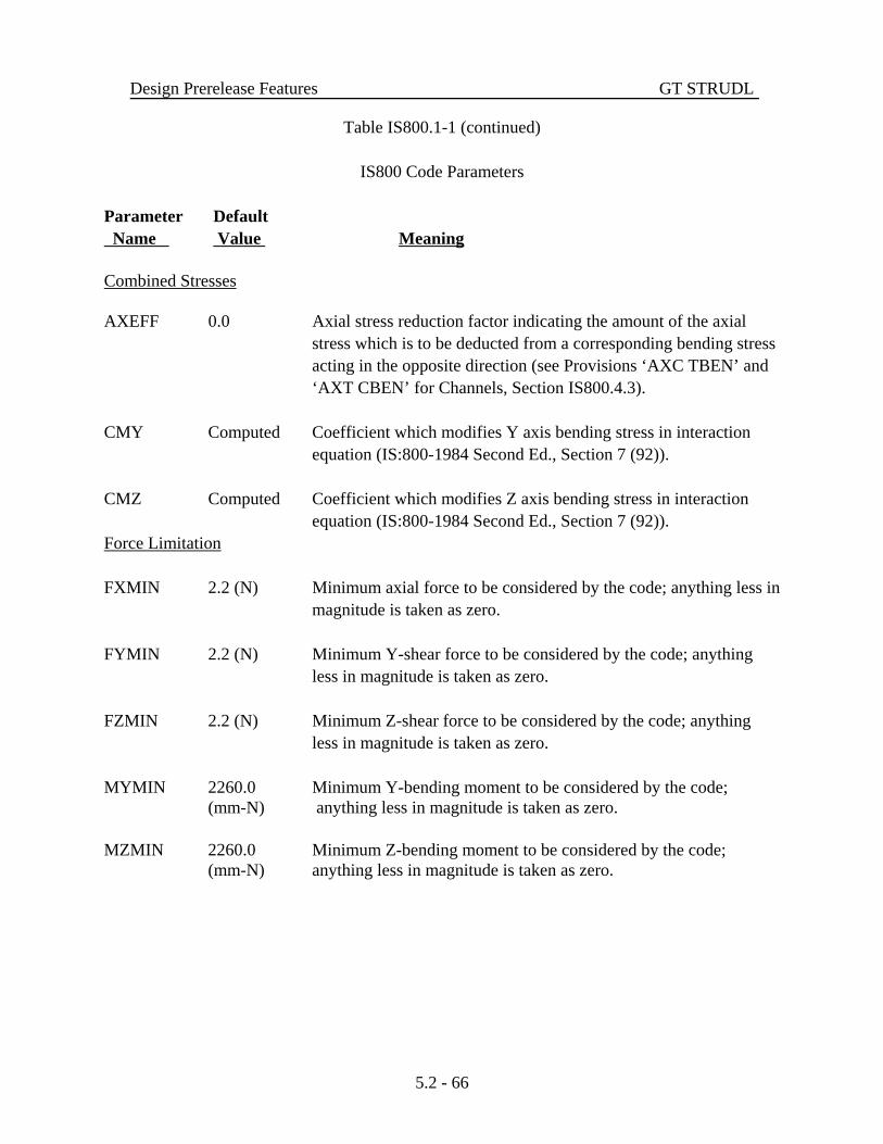
Design Prerelease Features GT STRUDL
5.2 - 66
Table IS800.1-1 (continued)
IS800 Code Parameters
Parameter Default Name Value Meaning
Combined Stresses
AXEFF 0.0 Axial stress reduction factor indicating the amount of the axialstress which is to be deducted from a corresponding bending stressacting in the opposite direction (see Provisions ‘AXC TBEN’ and‘AXT CBEN’ for Channels, Section IS800.4.3).
CMY Computed Coefficient which modifies Y axis bending stress in interactionequation (IS:800-1984 Second Ed., Section 7 (92)).
CMZ Computed Coefficient which modifies Z axis bending stress in interactionequation (IS:800-1984 Second Ed., Section 7 (92)).
Force Limitation
FXMIN 2.2 (N) Minimum axial force to be considered by the code; anything less inmagnitude is taken as zero.
FYMIN 2.2 (N) Minimum Y-shear force to be considered by the code; anythingless in magnitude is taken as zero.
FZMIN 2.2 (N) Minimum Z-shear force to be considered by the code; anythingless in magnitude is taken as zero.
MYMIN 2260.0 Minimum Y-bending moment to be considered by the code;(mm-N) anything less in magnitude is taken as zero.
MZMIN 2260.0 Minimum Z-bending moment to be considered by the code;(mm-N) anything less in magnitude is taken as zero.
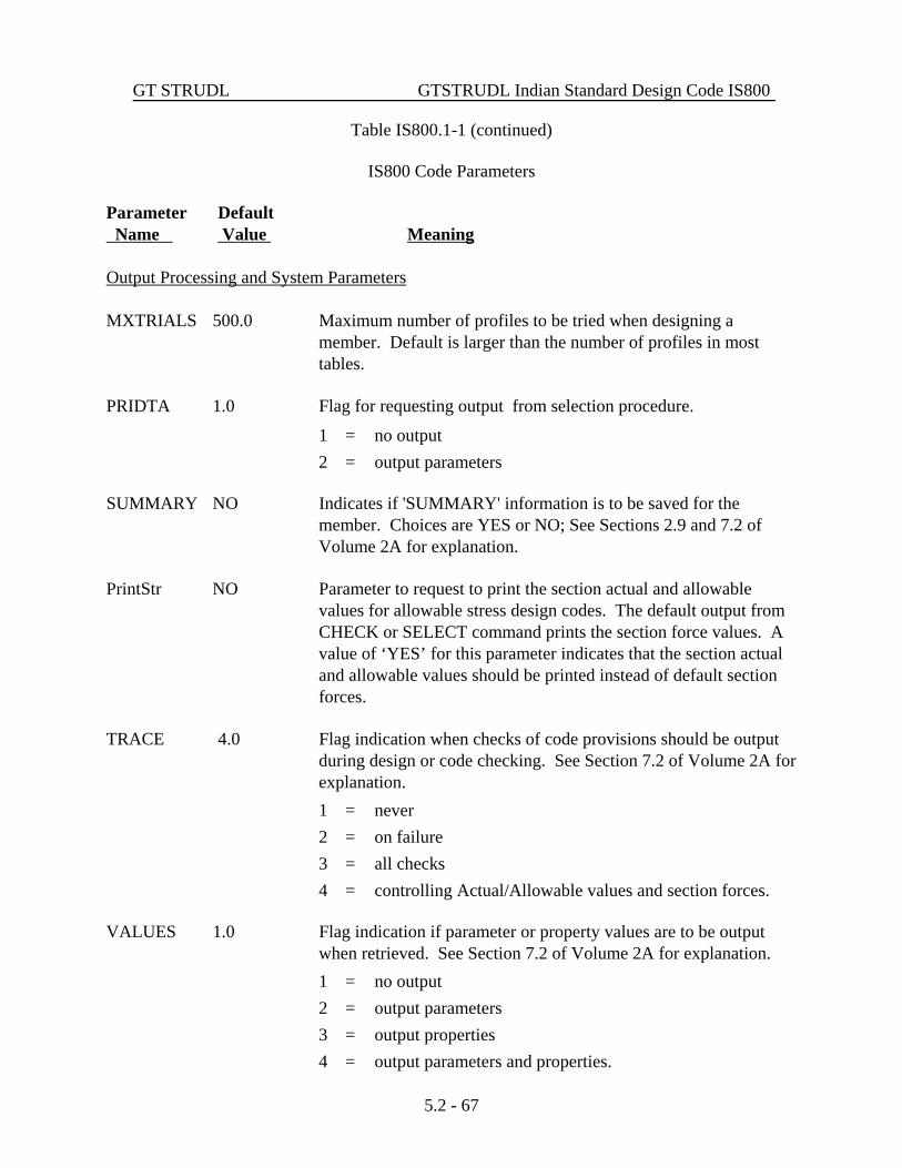
GT STRUDL GTSTRUDL Indian Standard Design Code IS800
5.2 - 67
Table IS800.1-1 (continued)
IS800 Code Parameters
Parameter Default Name Value Meaning
Output Processing and System Parameters
MXTRIALS 500.0 Maximum number of profiles to be tried when designing amember. Default is larger than the number of profiles in mosttables.
PRIDTA 1.0 Flag for requesting output from selection procedure.
1 = no output2 = output parameters
SUMMARY NO Indicates if 'SUMMARY' information is to be saved for themember. Choices are YES or NO; See Sections 2.9 and 7.2 ofVolume 2A for explanation.
PrintStr NO Parameter to request to print the section actual and allowablevalues for allowable stress design codes. The default output fromCHECK or SELECT command prints the section force values. Avalue of ‘YES’ for this parameter indicates that the section actualand allowable values should be printed instead of default sectionforces.
TRACE 4.0 Flag indication when checks of code provisions should be outputduring design or code checking. See Section 7.2 of Volume 2A forexplanation.1 = never2 = on failure3 = all checks4 = controlling Actual/Allowable values and section forces.
VALUES 1.0 Flag indication if parameter or property values are to be outputwhen retrieved. See Section 7.2 of Volume 2A for explanation.1 = no output2 = output parameters3 = output properties4 = output parameters and properties.

Design Prerelease Features GT STRUDL
5.2 - 68
Table IS800.1-2
GTSTRUDL Indian Standard Code(s)
Code ParameterName Table Application
IS800 IS800.2-1 Checks compliance of I shape, Single angle, Channel, Tee,Double angles, Solid Round bar, Pipe, Solid Square andRectangular bar, and Structural tubing shape profiles to the IndianStandard IS:800-1984 Specification (92).
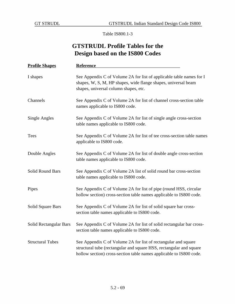
GT STRUDL GTSTRUDL Indian Standard Design Code IS800
5.2 - 69
Table IS800.1-3
GTSTRUDL Profile Tables for theDesign based on the IS800 Codes
Profile Shapes Reference
I shapes See Appendix C of Volume 2A for list of applicable table names for Ishapes, W, S, M, HP shapes, wide flange shapes, universal beamshapes, universal column shapes, etc.
Channels See Appendix C of Volume 2A for list of channel cross-section tablenames applicable to IS800 code.
Single Angles See Appendix C of Volume 2A for list of single angle cross-sectiontable names applicable to IS800 code.
Tees See Appendix C of Volume 2A for list of tee cross-section table namesapplicable to IS800 code.
Double Angles See Appendix C of Volume 2A for list of double angle cross-sectiontable names applicable to IS800 code.
Solid Round Bars See Appendix C of Volume 2A list of solid round bar cross-sectiontable names applicable to IS800 code.
Pipes See Appendix C of Volume 2A for list of pipe (round HSS, circularhollow section) cross-section table names applicable to IS800 code.
Solid Square Bars See Appendix C of Volume 2A for list of solid square bar cross-section table names applicable to IS800 code.
Solid Rectangular Bars See Appendix C of Volume 2A for list of solid rectangular bar cross-section table names applicable to IS800 code.
Structural Tubes See Appendix C of Volume 2A for list of rectangular and squarestructural tube (rectangular and square HSS, rectangular and squarehollow section) cross-section table names applicable to IS800 code.

Design Prerelease Features GT STRUDL
5.2 - 70
Table IS800.1-4
Permissible Steel Grade Based on 1993 AISC LRFD Second Edition, 1989 AISC ASD Ninth Edition,
and 1978 AISC Specification
Assumed Value of Yield Stress, Fy, and Minimum Tensile Strength, Fts.
Steel GradeASTM
Designation
Group Number Per ASTM A6Fy, Minimum Yield Stress (ksi)
Fu, Fts, Tensile Stress (ksi)
1 2 3 4 5
A36 3658
3658
3658
3658
3658
A529 4260
NA NA NA NA
A441 5070
5070
4667
4263
4263
A572-G42 4260
4260
4260
4260
4260
A572-G50 5065
5065
5065
5065
5065
A572-G60 6075
6075
NA NA NA
A572-G65 6580
NA NA NA NA
A242 5070
5070
4675
4263
4263
A588 5070
5070
5070
5070
5070
NA indicates that shapes in the corresponding group are not produced for that grade of steel. GTSTRUDL assumes Fy and Fts tobe zero in such cases and will not select profiles for these combinations of group number and steel grade. Yield strengths (Fy)and minimum tensile strengths (Fts) were obtained from the summary of ASTM specifications included in the 1993 AISC LRFDSecond Edition, 1989 AISC ASD Ninth Edition, and the 1978 AISC specification.

GT STRUDL ACI Code 318-99
5.2 - 71
5.2.4 ACI Code 318-99
Design of beams and columns by the 1999 ACI code has been added. Only membersdesignated as TYPE BEAM or TYPE COLUMN in a DESIGN DATA command can bePROPORTIONed when the METHOD is set to ACI318-99. When you specify ACI318-99,you will be reminded that it is a pre-release feature by a message (see the Example below).Note that CHECK is not available for codes after ACI318-77, including ACI318-99.
Example:METHOD ACI318-99 ****INFO_MET – 318-99 is a pre-release feature.
DESIGN DATA FOR MEMBER 1 TYPE BEAM RECTPROPORTION MEMBER 1
....ACTIVE CODE = ACI 318-99
....(the rest of the output is the same format as previouscodes)

Design Prerelease Features GT STRUDL
5.2 - 72
The table of CONSTANTS and assumed values for ACI 318-99 is shown below:
TABLE 2.4-1. CONSTANTS and Assumed Values for ACI 318-99CONSTANT Explanation ACI 318-99 Assumed Value
FCP Compressive strength of concrete, f'c 4000 psi
FY Yield strength of reinforcement, fy 60000 psi
WC Unit weight of plain concrete 145 pcf
DENSITY Unit weight of reinforced concrete (1) 150 pcf
FC Allow compr. stress in concrete, Fc A.3.1 0.45(FCP)
VU Ult. shear stress in beam with web reinf. (2) 11.5.6.9(5)
V Allow. shear stress in beam with web reinf. A.3.1(b)
RFSP Splitting ratio, fct/ (3) 9.5.2.3 6.7
FYST Yield strength of stirrups 60000 psi
FYSP Yield strength of spiral 60000 psi
FS Allowable tension stress in primary reinf. 20000 psi for
FSC Allowable compressive stress in column reinf. (4) A.3.2 Grades 40, 50
FV Allowable tension stress in stirrups (5) 24000 psi for
Grade 60
PHIFL Flexure capacity reduction factor 9.3.2 0.9
PHISH Shear capacity reduction factor 9.3.2 0.85
PHIBO Bond capacity reduction factor 9.3.2 0.85
PHITO Torsion capacity reduction factor 9.3.2 0.85
PHISP Spiral column capacity reduction factor 9.3.2 0.75
PHITI Tied column capacity reduction factor 9.3.2 0.7
BLFR Ratio of max p, (p - p') or (pw - pf) to pbal 10.3.3 0.75
PMAXCO Maximum allowable reinforced ratio in columns 10.9.1 0.08
PMINCO Minimum allowable reinforced ratio in columns 10.9.1 0.01
PMINFL Minimum allowable reinforced ratio in flexuralmembers
10.5.1 200/FY
ES Modulus of elasticity for reinf. steel 8.5.2 29x106psi
EC Modulus of elasticity for concrete 8.5.1 33(WC)1.5
EU Ult. strain in concrete at extreme comp. fiber 10.2.3 0.003

GT STRUDL ACI Code 318-99
5.2 - 73
Notes:
1. The constant 'DENSITY' is the GTSTRUDL constant of the same namewhich has been set to a value of 150 pcf for reinforced concrete.
2. VU is multiplied by PHISH internally.
3. Calculations for Vc and Tc are modified by replacing with RFSP/6.7( ) as per Section 11.2.1.1.
4. The assumed value of FSC is also limited to 30,000 psi maximum.
5. This value is defined only at the time of stirrup design.

Design Prerelease Features GT STRUDL
5.2 - 74
This page intentionally left blank.

GT STRUDL Rectangular and Circular Concrete Cross-Section Tables
5.2 - 75
5.2.5 Rectangular and Circular Concrete Cross-Section Tables
New tables have been added for rectangular and circular concrete cross sections. Thenew table for rectangular sections is called CONRECT and the new table for circularsections is called CONCIR. These tables are added to facilitate the modeling and analysisof concrete cross sections but may not be used in the design of concrete cross sections. Inorder to design concrete sections, the MEMBER DIMENSION command must be used (seeSection 2.5 of Volume 4 of the GTSTRUDL User Reference Manual).
The profiles in the CONCIR table are shown below where the name CIRxx indicatesa circular cross section and xx is the diameter in inches. Thus, CIR12 is a 12 inch diametercircular cross section.
CIR12 CIR24CIR14 CIR26CIR16 CIR28CIR18 CIR30CIR20 CIR32CIR22 CIR34
CIR36
The profiles in the CONRECT table are shown below where the name RECYYXZZindicates a rectangular cross section with a width of YY inches and a depth of ZZ inches.Thus, REC16X24 is 16 inch wide and 24 inch deep rectangular cross section.
REC6X12 REC8X12 REC10X12 REC12X12 REC14X12 REC16X12
REC6X14 REC8X14 REC10X14 REC12X14 REC14X14 REC16X14
REC6X16 REC8X16 REC10X16 REC12X16 REC14X16 REC16X16
REC6X18 REC8X18 REC10X18 REC12X18 REC14X18 REC16X18
REC6X20 REC8X20 REC10X20 REC12X20 REC14X20 REC16X20
REC6X22 REC8X22 REC10X22 REC12X22 REC14X22 REC16X22
REC6X24 REC8X24 REC10X24 REC12X24 REC14X24 REC16X24
REC6X26 REC8X26 REC10X26 REC12X26 REC14X26 REC16X26
REC6X28 REC8X28 REC10X28 REC12X28 REC14X28 REC16X28
REC6X30 REC8X30 REC10X30 REC12X30 REC14X30 REC16X30
REC6X32 REC8X32 REC10X32 REC12X32 REC14X32 REC16X32
REC6X34 REC8X34 REC10X34 REC12X34 REC14X34 REC16X34
REC6X36 REC8X36 REC10X36 REC12X36 REC14X36 REC16X36

Design Prerelease Features GT STRUDL
5.2 - 76
REC18X12 REC20X12 REC22X12 REC24X12 REC26X12 REC28X12
REC18X14 REC20X14 REC22X14 REC24X14 REC26X14 REC28X14
REC18X16 REC20X16 REC22X16 REC24X16 REC26X16 REC28X16
REC18X18 REC20X18 REC22X18 REC24X18 REC26X18 REC28X18
REC18X20 REC20X20 REC22X20 REC24X20 REC26X20 REC28X20
REC18X22 REC20X22 REC22X22 REC24X22 REC26X22 REC28X22
REC18X24 REC20X24 REC22X24 REC24X24 REC26X24 REC28X24
REC18X26 REC20X26 REC22X26 REC24X26 REC26X26 REC28X26
REC18X28 REC20X28 REC22X28 REC24X28 REC26X28 REC28X28
REC18X30 REC20X30 REC22X30 REC24X30 REC26X30 REC28X30
REC18X32 REC20X32 REC22X32 REC24X32 REC26X32 REC28X32
REC18X34 REC20X34 REC22X34 REC24X34 REC26X34 REC28X34
REC18X36 REC20X36 REC22X36 REC24X36 REC26X36 REC28X36
REC30X12 REC32X12 REC34X12 REC36X12
REC30X14 REC32X14 REC34X14 REC36X14
REC30X16 REC32X16 REC34X16 REC36X16
REC30X18 REC32X18 REC34X18 REC36X18
REC30X20 REC32X20 REC34X20 REC36X20
REC30X22 REC32X22 REC34X22 REC36X22
REC30X24 REC32X24 REC34X24 REC36X24
REC30X26 REC32X26 REC34X26 REC36X26
REC30X28 REC32X28 REC34X28 REC36X28
REC30X30 REC32X30 REC34X30 REC36X30
REC30X32 REC32X32 REC34X32 REC36X32
REC30X34 REC32X34 REC34X34 REC36X34
REC30X36 REC32X36 REC34X36 REC36X36

GT STRUDL ASD9-E Code Parameters
5.2 - 77
5.2.6 ASD9-E Code
A special Ninth Edition AISC allowable stress design code for W shapes has beenimplemented. The code name is ASD9-E. This code is based on the Ninth Edition AISCASD except the equations have been modified to include modulus of elasticity (constant E).ASD9-E is applicable to W shapes only. This code is useful for structures where E andpossibly other material data must be modified to account for high temperature. Parametersfor the ASD9-E Code are shown below:
ASD9-E.1.2 ASD9-E Code
The ASD9-E Code of GTSTRUDL may be used to select or check I shape cross-section. The term I shapes is used to mean W, S, M, and HP profiles. This code is primarilybased on the AISC "Specification for Structural Steel buildings, Allowable Stress Designand Plastic Design" adopted June 1, 1989. The Specification is contained in the NinthEdition of the AISC Manual of Steel Construction, Allowable Stress Design (72). TheASD9-E code utilizes the allowable stress design techniques of the AISC Specification. Theequations of the AISC have been modified to include constant E (modulus of elasticity).ASD9-E is similar to ASD9 code but it is only applicable to I shape cross-sections.
The purpose of this code is to be able to code check structures that experience hightemperature or when ever the modulus of elasticity of the steel is different than standardvalue of 29,000 ksi (. 200 kN/mm2). Equations in the AISC ASD specification have beensimplified by assuming the modulus of elasticity of the steel is equal to 29,000 ksi (. 200kN/mm2). The equations in the GTSTRUDL ASD9-E code are the original equations thatcontains the modulus of elasticity.
Design criteria for the I shape cross-section are presented in Section ASD9-E.4. Adetailed discussion is presented on the allowable stresses for I shape cross-section in SectionASD9-E.4.2. The following assumptions are made throughout the ASD9-E Code.
1. The member under consideration is made of one grade of steel.
2. Torsional stresses are usually small when compared to axial and bendingstresses, and may be neglected. No checks are made for torsion. Thedesigner is reminded to check the torsional stresses whenever they becomesignificant.
3. Web stiffeners are considered for web shear stress, but they are not designed.
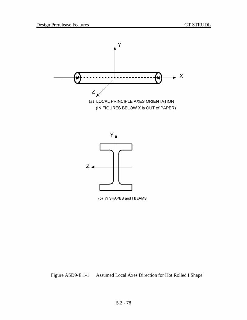
Design Prerelease Features GT STRUDL
5.2 - 78
Figure ASD9-E.1-1 Assumed Local Axes Direction for Hot Rolled I Shape
GT STRUDL ASD9-E Code Parameters
5.2 - 79
Tensile or compressive axial stresses, bi-axial bending, shear stresses, and combinedstresses are considered by ASD9-E. Provisions for slender compression elements, AppendixB of AISC Specification, are included when necessary. Parameters allowing for the changeswhich occur in structural steel at high temperatures have been included and may be invokedat the user's discretion.
The properties used for I shape cross-section is defined under Section ASD9-E.2.The parameters used by ASD9-E are discussed in detail in Table ASD9-E.1-1 and SectionASD9-E.3. Section ASD9-E.4.1 defines the general nomenclature used in describing theASD9-E Code. The equations used in ASD9-E to determine the acceptability of a profileare described in detail for I shape cross-section in Section ASD9-E.4.2.

Design Prerelease Features GT STRUDL
5.2 - 80
This page intentionally left blank.

GT STRUDL ASD9-E Code Parameters
5.2 - 81
Table ASD9-E.1-1
ASD9-E Code Parameters
Parameter Default Name Value Meaning
CODE Required Identifies the code to be used for member checking ormember selection. Specify ASD9-E for code name.
TBLNAM WSHAPES9 Identifies the table of profiles to be used during selection.See Table ASD9-E.1-2 for choices.
CODETOL 0.0 Percent variance from 1.0 for compliance with the provi-sions of a code. The ratio of Actual/Allowable must be lessthan or equal to [1.0 + CODETOL/100].
PF 1.0 Area reduction factor for holesout in members subject toaxial tension.
A/H 10000.0 Ratio of clear span between transverse stiffeners to cleardistance between flanges. Used in computing allowableshear stress. Default approximates infinity.
ALSTRINC 0.0 Allowable stress increase value. This parameter can beused to specify the 1/3 allowable stress increase for thewind or seismic loads. The user specified value for thisparameter must be followed by the load list. An examplefor this parameter is to specify a value of 33.3333 followedby a load list.
Material Properties
STEELGRD A36 Identifies the grade of steel from which a member is made.See Table ASD9-E.1-3 for steel grades and their properties.
FYLD Computed Yield stress of member. Computed from STEELGRD if notgiven.
FTS Computed Minimum tensile strength of member. Computed fromSTEELGRD if not given.
REDFYLD 1.0 Reduction factor for FYLD. This factor times FYLD givesthe FY value used by the code. Used to account for proper-ty changes at high temperatures.

ASD9-E Code Parameters GT STRUDL
5.2 - 82
Table ASD9-E.1-1 (continued)
ASD9-E Code Parameters
Parameter Default Name Value Meaning
Material Properties (continued)
REDFTS 1.0 Reduction factor for FTS. Similar to REDFYLD.
REDE 1.0 Reduction factor for E, the modulus of elasticity. Similar toREDFYLD.
Slenderness Ratio
SLENCOMP Computed Maximum permissible slenderness ratio (KL/r) for membersubjected to axial compression. When no value is specifiedfor this parameter, the value of 200 is used for the maxi-mum slenderness ratio.
SLENTEN Computed Maximum permissible slenderness ratio (L/r) for membersubjected to axial tension. When no value is specified forthis parameter, the value of 300 is used for the maximumslenderness ratio.
K-Factors
COMPK NO Parameter to request the computation of the effective lengthfactors KY and KZ (Sections 2.2 and 2.3 of Volume 2A).
YES = Compute KY and KZ factors
KY = Compute KY only.
KZ = Compute KZ only.
NO = Use default or specified values for KY and KZ.
KY 1.0 Effective length factor for buckling about the local Y axisof the profile. See Sections 2.2 and 2.3 of Volume 2A forGTSTRUDL computation of effective length factor, KY.
KZ 1.0 Effective length factor for buckling about the local Z axisof the profile. See Sections 2.2 and 2.3 of Volume 2A forGTSTRUDL computation of effective length factor, KZ.

GT STRUDL ASD9-E Code Parameters
5.2 - 83
Table ASD9-E.1-1 (continued)ASD9-E Code Parameters
Parameter Default Name Value Meaning
K-Factors (continued)
Print-K YES Parameter to print the computed K-factor values after thedefault code check or select command output (TRACE 4output). The default value of ‘YES’ for this parameterindicates that the computed K-factor values should beprinted after the code check or select command output. Thecolumn names attached to the start and end of the codechecked member is also printed. This printed informationallows the user to inspect the automatic detection of thecolumns attached to the start and end of the designedmember. A value of ‘NO’ indicates that K-factor valuesand the names of the attached columns to the start and endof the designed member should not be printed.
SDSWAYY YES Indicates the presence or absence of sidesway about thelocal Y axis.
YES = sidesway permitted.
NO = sidesway prevented.
SDSWAYZ YES Indicates the presence or absence of sidesway about thelocal Z axis.
YES = sidesway permitted.
NO = sidesway prevented.
CantiMem NO Parameter to indicate that a member or a physical memberwhich is part of a cantilever truss should be considered asa cantilever in the K-factor computation. True cantilevermembers or physical members are detected automatically.
NO = member of physical member is not cantilever,
YES = member of physical member is cantilever.
GAY Computed G-factor at the start joint of the member. GAY is used inthe calculation of effective length factor KY (see parameterCOMPK, KY, and Sections 2.2 and 2.3 of Volume 2A).

ASD9-E Code Parameters GT STRUDL
5.2 - 84
Table ASD9-E.1-1 (continued)ASD9-E Code Parameters
Parameter Default Name Value Meaning
K-Factors (continued)
GAZ Computed G-factor at the start joint of the member. GAZ is used inthe calculation of effective length factor KZ (see parameterCOMPK, KZ, and Sections 2.2 and 2.3 of Volume 2A).
GBY Computed G-factor at the end joint of the member. GBY is used in thecalculation of effective length factor KY (see parameterCOMPK, KY, and Sections 2.2 and 2.3 of Volume 2A).
GBZ Computed G-factor at the end joint of the member. GBZ is used in thecalculation of effective length factor KZ (see parameterCOMPK, KZ, and Sections 2.2 and 2.3 of Volume 2A).
Buckling Length
LY Computed Unbraced length for buckling about the local Y axis of theprofile. Computed as length of member.
LZ Computed Unbraced length for buckling about the local Z axis of theprofile. Computed as length of member.
FRLY 1.0 Fractional form of the parameter LY, allows unbracedlength to be specified as fractions of the total length. Usedonly when LY is computed.
FRLZ 1.0 Fractional form of the parameter LZ, similar to FRLY.Used only when LZ is computed.
Flexural-Torsional Buckling
FLTORBUK YES Indicates the consideration of flexural-torsional bucklingcheck.
YES = check flexural-torsional buckling.
NO = do not check flexural-torsional buckling.

GT STRUDL ASD9-E Code Parameters
5.2 - 85
Table ASD9-E.1-1 (continued)ASD9-E Code Parameters
Parameter Default Name Value Meaning
Flexural-Torsional Buckling (continued)
KX 1.0 Effective length factor for torsional buckling about the localX axis of the profile. This parameter is used in flexural-torsional buckling stress, Fe computations.
LX Computed Unbraced length for torsional buckling about the local Xaxis of the profile. Computed as length of member. Thisparameter is used in flexural-torsional buckling stress, Fecomputations.
FRLX 1.0 Fractional form of the parameter LX, allows unbracedlength to be specified as fractions of the total length. Usedonly when LX is computed.
Bending Stress
CB Computed Coefficient used in computing allowable compressivebending stress (AISC ASD Ninth Ed. Section F1.3).
UNLCF Computed Unbraced length of the compression flange. Computed aslength of member. In this parameter no distinction is madebetween the unbraced length for the top or bottom flange.See UNLCFTF or UNLCFBF.
FRUNLCF 1.0 Fractional form of the parameter UNLCF, allows unbracedlength to be specified as fractions of the total length. Usedonly when UNLCF is computed.
UNLCFTF Computed Unbraced length of the compression flange for the topflange. When no value is specified, UNLCF and FRUNLCFis used for this parameter.
UNLCFBF Computed Unbraced length of the compression flange for the bottomflange. When no value is specified, UNLCF and FRUNLCFis used for this parameter.

ASD9-E Code Parameters GT STRUDL
5.2 - 86
Table ASD9-E.1-1 (continued)ASD9-E Code Parameters
Parameter Default Name Value Meaning
Combined Stresses
AXEFF 0.0 Axial stress reduction factor indicating the amount of theaxial stress which is to be deducted from a correspondingbending stress acting in the opposite direction.
CMY Computed Coefficient which modifies Y axis bending stress in interac-tion equation (AISC ASD Ninth Ed. Section H1).
CMZ Computed Coefficient which modifies Z axis bending stress in interac-tion equation (AISC ASD Ninth Ed. Section H1).
Force Limitation
FXMIN 0.5(lb) Minimum axial force to be considered by the code;anything less in magnitude is taken as zero.
FYMIN 0.5(lb) Minimum Y-shear force to be considered by the code;anything less in magnitude is taken as zero.
FZMIN 0.5(lb) Minimum Z-shear force to be considered by the code;anything less in magnitude is taken as zero.
MYMIN 20.0(in-lb) Minimum Y-bending moment to be considered by the code;anything less in magnitude is taken as zero.
MZMIN 20.0(in-lb) Minimum Z-bending moment to be considered by the code;anything less in magnitude is taken as zero.
Output Processing and System Parameters
MXTRIALS 500.0 Maximum number of profiles to be tried when designing amember. Default is larger than the number of profiles inmost tables.
SUMMARY NO Indicates if 'SUMMARY' information is to be saved for themember. Choices are YES or NO; See Sections 2.9 and 7.2of Volume 2A for explanation.

GT STRUDL ASD9-E Code Parameters
5.2 - 87
Table ASD9-E.1-1 (continued)ASD9-E Code Parameters
Parameter Default Name Value Meaning
Output Processing and System Parameters (continued)
PrintStr NO Parameter to request to print the section stress values forallowable stress design codes. The default output fromCHECK or SELECT command prints the section forcevalues. A value of ‘YES’ for this parameter indicates thatthe section stress values should be printed instead of defaultsection forces.
TRACE 4.0 Flag indication when checks of code provisions should beoutput during design or code checking. See Section 7.2 ofVolume 2A for explanation.
1 = never
2 = on failure
3 = all checks
4 = controlling Actual/Allowable values and sectionforces.
VALUES 1.0 Flag indication if parameter or property values are to beoutput when retrieved. See Section 7.2 of Volume 2A forexplanation.
1 = no output
2 = output parameters
3 = output properties
4 = output parameters and properties.

ASD9-E Code Parameters GT STRUDL
5.2 - 88
This page intentionally left blank.

GT STRUDL ASD9-E Code Parameters
5.2 - 89
Table ASD9-E.1-2GTSTRUDL I shape Profile Tables for the
Design based on the ASD9-E Code*(I shapes, Universal Beams, Universal Columns, Joists, Piles, etc.)
Table Name Reference
AISC Tables (American Institute of Steel Construction)
W-LRFD3 W shapes from 1999 AISC LRFD Third Edition (96)
M/S/HPL3 M, S, and HP shape profiles from 1999 AISC LRFD Third Edition (96)
WSHAPES9 W shapes from 1989 AISC ASD Ninth Edition (72)
M/S/HP9 M, S, and HP shapes from 1989 AISC ASD Ninth Edition (72)
WBEAM9 W shapes commonly used as beams from 1989 AISC ASD Ninth Edition(72)
WCOLUMN9 W shapes commonly used as columns from 1989 AISC ASD NinthEdition (72)
WSHAPESM W shape from AISC Metric “WSHAPES” table (83)
M/S/HPM M, S, and HP shape profiles from AISC Metric “M SHAPES, SSHAPES, and HP SHAPES” table (83)
WBEAMM W shape profiles commonly used as beams from AISC Metric“WSHAPES” table (83)
WCOLUMNM W shape profiles commonly used as columns from AISC Metric“WSHAPES” table (83)
STEELW78 W shapes from 1978 AISC ASD Eighth Edition (33)
HP/S/M HP, S, and M shapes from 1978 AISC ASD Eighth Edition (33)
W78BEAM W shapes commonly used as beams from 1978 AISC ASD EighthEdition (33)
W78COLUM W shapes commonly used as columns from 1978 AISC ASD EighthEdition (33)
STEELW W shapes from 1969 AISC ASD Seventh Edition (16)
WCOLUMN W shapes commonly used as columns from 1969 AISC ASD SeventhEdition (16)
* See design code for applicable cross-sections* See Appendix C of Volume 2A for Table description and profile names* Also see Appendix C of Volume 2A for additional Table names

ASD9-E Code Parameters GT STRUDL
5.2 - 90
Table ASD9-E.1-2 (continued)
GTSTRUDL I shape Profile Tables for theDesign based on the ASD9-E Code*
(I shapes, Universal Beams, Universal Columns, Joists, Piles, etc.)
Table Name Reference
Brazilian Standard Tables, NBR 5884 2000
CS I shapes from Brazilian Standard, ABNT, NBR 5884:2000
CVS I shapes from Brazilian Standard, ABNT, NBR 5884:2000
VS I shapes from Brazilian Standard, ABNT, NBR 5884:2000
British Standard Tables, BS 5950
UNIBEAMS British Universal Beam profiles from 1996 BS 5950 Section Properties,4th Edition (82)
UNICOL British Universal Column profiles from 1996 BS 5950 SectionProperties, 4th Edition (82)
JOISTS British Joist profiles from 1996 BS 5950 Section Properties, 4th Edition(82)
UBPILES I shape profiles from British “UNIVERSAL BEARING PILES” table(82)
European Tables
HEA H shaped (HE-A) profiles from Breite I-Träger, Reihe HE-A. Theprofiles are from "STAHLBAU-PROFILE, 21., neu bearbeitete underweiterte Auflage, überarbeiteter Nachdruck 1997"
HEB H shaped (HE-B) profiles from Breite I-Träger, Reihe HE-B. Theprofiles are from "STAHLBAU-PROFILE, 21., neu bearbeitete underweiterte Auflage, überarbeiteter Nachdruck 1997"
HEM H shaped (HE-M) profiles from Breite I-Träger, Reihe HE-M. Theprofiles are from "STAHLBAU-PROFILE, 21., neu bearbeitete underweiterte Auflage, überarbeiteter Nachdruck 1997"
* See design code for applicable cross-sections* See Appendix C of Volume 2A for Table description and profile names* Also see Appendix C of Volume 2A for additional Table names

GT STRUDL ASD9-E Code Parameters
5.2 - 91
Table ASD9-E.1-2 (continued)
GTSTRUDL I shape Profile Tables for the Design based on the ASD9-E Code*
(I shapes, Universal Beams, Universal Columns, Joists, Piles, etc.)
Table Name Reference
European Tables (Continued)
IPE I shaped (IPE) profiles from Mittelbreite I-Träger, IPE-Reihe. Theprofiles are from "STAHLBAU-PROFILE, 21., neu bearbeitete underweiterte Auflage, überarbeiteter Nachdruck 1997"
EUROPEAN This table contains profiles from IPE, HEA, HEB, and HEM tables
Indian Standard Tables from IS808:1989
ISBEAMS I shape beam sections (medium flange beams, junior and light weightbeams) from Tables 2.1 and 2.2 of the Indian Standard IS 808:1989,DIMENSIONS FOR HOT ROLLED STEEL BEAM, COLUMN,CHANNEL AND ANGLE SECTIONS, Third Revision (93)
ISCOLUMN I shape column/heavy weight beam sections (column and heavy weightbeams) from Table 3.1 of the Indian Standard IS 808:1989,DIMENSIONS FOR HOT ROLLED STEEL BEAM, COLUMN,CHANNEL AND ANGLE SECTIONS, Third Revision (93)
* See design code for applicable cross-sections* See Appendix C of Volume 2A for Table description and profile names* Also see Appendix C of Volume 2A for additional Table names

ASD9-E Code Parameters GT STRUDL
5.2 - 92
Table ASD9-E.1-3
Permissible Steel Grade Based on 1989 AISC ASD NinthEdition Specification
Assumed Value of Yield Stress, Fy, and Minimum Tensile Strength, Fts.
Steel GradeASTM
Designation
Group Number Per ASTM A6Fy, Minimum Yield Stress (ksi)
Fu, Fts, Tensile Stress (ksi)
1 2 3 4 5
A36 3658
3658
3658
3658
3658
A529 4260
NA NA NA NA
A441 5070
5070
4667
4263
4263
A572-G42 4260
4260
4260
4260
4260
A572-G50 5065
5065
5065
5065
5065
A572-G60 6075
6075
NA NA NA
A572-G65 6580
NA NA NA NA
A242 5070
5070
4667
4263
4263
A588 5070
5070
5070
5070
5070
NA indicates that shapes in the corresponding group are not produced for that grade of steel. GTSTRUDL assumes Fy andFts to be zero in such cases and will not select profiles for these combinations of group number and steel grade. Yieldstrengths (Fy) and minimum tensile strengths (Fts) were obtained from the summary of ASTM specifications included inthe 1989 AISC ASD Ninth Edition specification.

GT STRUDL DESIGN SLAB Command
5.2 - 93
DESIGN SLAB (REINFORCEMENT) (USING)
WOOD (AND) (ARMER)AVERAGE
MAXIMUMCALCULATE (RESULTANT) (ELEMENT) (FORCES)
(ALONG)
(CUT 'a'i )
JOINTSNODES list ELEMENT list (TABLE
ASTM UNESCO
TOP (FACE) (BARS i ) (SPACING v )BOTTOM (FACE) (BARS i ) (SPACING v )BOTH (FACES) (BARS i ) (SPACING v )
11 2
*
2 1
3 2
4 3
−→⎧
⎨⎩
⎫⎬⎭
⎧⎨⎪
⎩⎪
⎫⎬⎪
⎭⎪−
⎧⎨⎩
⎫⎬⎭
⎧⎨⎩
⎫⎬⎭
→⎧⎨⎩
⎫⎬⎭−
⎧⎨⎪
⎩⎪
⎫
)
⎬⎪
⎭⎪−
→⎧⎨⎩
⎫⎬⎭
−INNER (LAYER)
OUTER (LAYER) (COVER v ) (LINEAR (TOLERANCE) v )
(TORSIONAL (MOMENT) (WARNING) v )
4 5
6
5.2.7 Design of Flat Plates Based on the Results of Finite ElementAnalysis (The DESIGN SLAB Command)
The goal of the DESIGN SLAB command is to select reinforcing steel for concreteflat plate systems using finite elements as a tool for the determination of design moments.
Instead of dealing with results on an element-by-element basis, the user will be ableto design the reinforcing steel for slab systems based on cuts. Here, the term cut refers tothe cross-section of a strip at a particular location to be designed. A cut is defined by twonodes identifying the start and end of the cut, and by an element in the plane of the cut.
Once the definition of the cut has been determined, the resultant forces along the cutare computed using either moment resultants (otherwise known as the Wood and Armermethod) or element force results (using the CALCULATE RESULTANT command, asdescribed in Section 2.3.7.3 of Volume 3 of the Reference Manuals). The final designmoment is determined by computing the resultant moment acting on the cut for each loadingcondition, and reducing these moments to a design envelope.
Once the design envelope is computed, the cross-section is designed according toACI 318-05 either using default design parameter or with certain user specified designparameters such as the bar size or spacing.
An important distinction is to note that each cut is designed independently from allother cuts. That is, a cut specified in one region is independent with respect to a design inanother region. As such, if the user wishes to use the same bar size over multiple adjacentcuts, this information must be specified for each cut.
The form of the command is as follows:

Design Prerelease Features GT STRUDL
5.2 - 94
where,
‘a’ or i1 refer to an optional alphanumeric or integer cut name
list1 = list containing ID’s of the start and end node of the cut
list2 = list containing the ID of an element in the plane of the cut
i2 = bar size to be used for bars on the top surface of the slab
i3 = bar size to be used for bars on the bottom surface of the slab
i4 = bar size to be used for both the top and bottom surfaces of the slab
v1 = reinforcing bar spacing to be used on the top surface of the slab
v2 = reinforcing bar spacing to be used on the bottom surface of the slab
v3 = reinforcing bar spacing to be used on both surfaces of the slab
v4 = optional user-specified cover distance for reinforcing bars
v5 = linear tolerance used in element selection rules for momentcomputation
v6 = optional ratio of torsion to bending moment allowed on the cross-section
TOP = element surface with +ZPLANAR coordinate
BOTTOM = element surface with -ZPLANAR coordinate
Explanation:
The DESIGN SLAB command allows the user to communicate all data necessary forthe reinforcing steel design. This information is processed and a design is calculated basedon the input. The command is designed to provide varying levels of control for the user soas to make the command as broadly applicable as possible.
The user must first define the cut. A cut is defined by a start and end node ID, andan element ID in the plane of the cut. The user has the option of giving each cut analphanumeric name for organizational purposes. The purpose of the required element ID isto determine the appropriate plane to design in the event that multiple planes of finiteelements intersect along the cut, as defined by the start and end node. An example wherethis might occur is the intersection of a slab with a shear wall. In this case, a misleadingdesign could be generated if the slab was designed using the forces in the shear wall. Thecut definition constitutes all information required to compute the resultant forces actingalong the cut.

GT STRUDL DESIGN SLAB Command
5.2 - 95
The total moment acting on a cut cross-section is computed using one of twomethods. The use of moment resultants, also known as the Wood and Armer method, isimplemented as the default method. In this method, the moment resultants MXX, MYY, andMXY are resolved on a per node basis along the cut, and either the average effect or themaximum effect on the cut is applied to the entire cross-section.
The other option for moment computation is based on the use of element forces. Inthis method, the total resultant moment acting on the cross-section is computed using theCALCULATE RESULTANT command, and the element force nodal moments are resolvedfor each node of each element adjacent to the cut.
Once the cut has been defined, the user may indicate parameters to be used to designthe system. The user may constrain the bar size or spacing to a certain value, either for thetop face, bottom face, or for both faces. In this case, the final design will utilize theinformation provided. If the bar size is constrained, the appropriate spacing of bars isdetermined. If the bar spacing is constrained, the appropriate bar size is determined. In thecase that the user supplies a bar size and spacing for the cut, the application will simplycheck the strength of the cross-section against the computed design envelope according toACI 318. If the user specifies no design constraints, the application assumes a bar size anddesigns the section to satisfy ACI 318. As such, the user maintains explicit control over thefunction of the application.
The user may also specify which layer of bars to be designed, using the modifierINNER or OUTER. These refer to the location of reinforcing bars on each surface. At mostslab locations, reinforcement is placed in two perpendicular directions on both surfaces ofthe slab. Since each layer of reinforcement cannot occupy the same space, one layer mustbe placed on top of the other. OUTER refers to the layer closest to the surface, whileINNER refers to the layer nearest the center of the slab.
All user-specified constraints, such as concrete compressive strength, yield strength,cover, and spacing are checked against ACI minimum/maximum values, as specified in ACI318-02. The thickness of the cross-section is determined internally based on the modeledthickness of the user-specified element.
With respect to the interpretation of results, “top” always refers to the face of the slabon the +ZPLANAR side of the element, and “bottom” always refers to the face of the slabon the -ZPLANAR side of the element. “Positive bending” refers to bending that producestension on the bottom face of the slab and compression on the top face, as definedpreviously. “Negative bending” produces tension on the top face and compression on thebottom face, as defined previously.

Design Prerelease Features GT STRUDL
5.2 - 96
Requirements:
The MATERIAL REINFORCED CONCRETE command must be specified beforethe DESIGN SLAB. The MATERIAL REINFORCED CONCRETE command initializesthe RC capabilities of GT STRUDL and sets the relevant material and design quantities totheir default values for design. At this point, the user can issue the CONSTANTS commandto modify any material properties to be used in the design. The default values are:
ECU = 0.003ES = 29,000,000 psiFCP = 4000 psiFY = 60,000 psiPHIFL = 0.9
The STIFFNESS command must be issued prior to the DESIGN SLAB command.The STIFFNESS command solves the global equilibrium equation and computes thequantities required for the determination of the bending moments that the DESIGN SLABcommand uses.
Only elements known to appropriately model the behavior of slab systems areincluded in the computation of design forces. For a flat plate system, only plate bending andplate elements are used. Thus, if the user models the system using plane stress / plane strainelements, and then issues the DESIGN SLAB command, a warning message is output andthe command is ignored.
Plate bending elements supported include the BPHT, BPR, BPHQ, CPT, and IPBQQfinite elements. General plate elements supported include the SBCT, SBCR, SBHQ,SBHQCSH, SBHT, SBHT6, and SBHQ6 finite elements.
Usage:
Studies have shown that the CALCULATE RESULTANT ELEMENT FORCEoption of the DESIGN SLAB command is only applicable in regions where the cutorientation is generally orthogonal to the directions of principle bending. If the geometryof a region dictates that a cut be oriented non-orthogonally to the principal bendingdirections, a significant torsional effect may occur. In this case, the Wood and Armermethod must be employed due to its ability to correctly compute the ultimate moment in astrong torsion field. In the DESIGN SLAB command, the user is warned if the element forceimplementation computes a resultant torsion greater than 10% of the resultant bendingmoment on a particular cross-section. The user may modify the torsion warning thresholdvia the modifiers TORSIONAL MOMENT WARNING. If there is any question of theorientation of the cut with respect to the directions of principal bending, the user shouldinvestigate the behavior in the finite element results section of GTMENU.

GT STRUDL DESIGN SLAB Command
5.2 - 97
Usage Example: Description of Example Structure
The example structure is a rectangular slab system, shown in Figure 5.2.7-1. The clear spanof the structure is thirty feet, and the slab strip has a width of ten feet. The two ends of theslab are fully fixed, while the thirty foot sides are free, resembling a fixed-fixed beam. Theslab is one foot thick and constructed of normal strength concrete with FCP = 4000 psi. Theexample structure can be idealized as a subset of a larger slab system, perhaps the designstrip running between two column faces in an interior region. The structure is loaded witha distributed surface pressure of 150 psf over the entire surface of the slab.
Figure 5.2.7-1 Example Flat Plate Structure (PLAN)

Design Prerelease Features GT STRUDL
5.2 - 98
GT STRUDL Finite Element Model
The example structure was modeled in GT STRUDL using PLATE BENDING finiteelements. The BPHQ element was utilized, and the configuration modeled corresponded toa mesh of ten elements by thirty elements. The model contained 300 finite elements and 341nodes. The material properties were the default values associated with the MATERIALREINFORCED CONCRETE command. All 6 degrees of freedom were restrained at eachnode along the supported ends of the slab system. Each element was loaded with a surfacepressure of 150 psf, resulting in a confirmed summation of vertical reaction of 45,000 lb.
Figure 5.2.7-2 Example Finite Element Model
Definition of Cut Cross-Sections
Two “cuts” are considered for the verification example, as shown in Figure 5.2.7-1.
Cut 1-1:
The cross-section Cut 1-1 is defined along the fixed support at the end of the slab strip andrepresents the maximum “negative moment” section in the slab where top reinforcing steelwould be required. Cut 1-1 originates at node #1 and terminates at node #11. The elementsalong Cut 1-1 are elements #1-#10. The command given for Cut 1-1 is:
“design slab using calculate resultant joi 1 11 ele 1 top bar 5"

GT STRUDL DESIGN SLAB Command
5.2 - 99
In this case, the user requests that a slab cross-section beginning at node #1, ending at node#11, and in the plane of element #1 be reinforced according to the section moment computedusing the CALCULATE RESULTANT command. The user has specified that #5 bars areto be used on the top surface, indicating that spacing is to be computed. The results of theDESIGN SLAB command are shown in the following table.
Calculation Surface Bar Spacing Area Prov. Moment Strength Moment Required
# in sq. in. lb-in lb-in
DESIGN SLAB Top 5 13.0 2.862 1561006.4 1354381.5
DESIGN SLAB Bottom NA NA NA NA NA
The GTSTRUDL output for this example is as follows:
** FLAT PLATE SLAB DESIGN BASED ON THE RESULTS OF FINITE ELEMENT ANALYSIS **
PROBLEM - VFE103 TITLE - DESIGN SLAB VERIFICATION - VERIFY DESIGN CALCULATIONS
RELEVANT ACTIVE UNITS: INCH LB
NUMBER OF ACTIVE LOADINGS: 1
REINFORCEMENT ORIENTATION PERPENDICULAR TO A CUT BEGINNING AT NODE 1 AND TERMINATING AT NODE 11 AND IN THE PLANE OF ELEMENT 1
** ELEMENT FORCE IMPLEMENTATION **
** DESIGN MOMENT ENVELOPE **
NEGATIVE MOMENT = -1354381.48 DUE TO LOAD 150psf POSITIVE MOMENT = 0.00 DUE TO LOAD (none)
NOTE: - Negative moment produces tension on the positive PLANAR Z surface, requiring TOPbars. - Positive moment produces compression on the positive PLANAR Z surface, requiringBOTTOM bars.
** SLAB CROSS-SECTION **
Width Depth FCP FY Cover Layer ________________________________________________________________________
120.00 12.00 4000.00 60000.00 0.750 Inner
** DESIGN RESULTS (per ACI 318-05) **
Face Bar Spacing AS PROV'D MOMENT STRENGTH MOMENT REQ'D STATUS _________________________________________________________________________________________
TOP # 5 13.000 2.862 1561006.4280 1354381.4844 PASSES
BOTTOM ( Reinforcement Not Required )

Design Prerelease Features GT STRUDL
5.2 - 100
Cut 2-2:
The cross-section Cut 2-2 is defined along the center line in the middle region of theslab strip and represents the maximum “positive moment” section in the slab wherebottom reinforcing steel would be required. Cut 2-2 originates at node #166 andterminates at node #176. The elements along Cut 2-2 are elements #141-#150 on oneside and #151-#160 on the other side. The command given for Cut 2-2 Case 1 is:
“design slab wood and armer joi 166 176 ele 141 table unesco bottom spacing10 outer layer"
In this case, the user requests that a slab cross-section beginning at node #166, endingat node #176, and in the plane of element #141 be reinforced according to the averageeffect produced by the Wood and Armer method. The user has specified thatUNESCO metric reinforcing bars are to be used. The bottom reinforcement spacinghas been constrained to 10 inches, and the reinforcement to be designed is located inthe outer layer. The results of the DESIGN SLAB command are shown in thefollowing table:
Calculation Surface Bar Spacing Area Prov. Moment Strength Moment Required
# in sq. in. lb-in lb-in
DESIGN SLAB Bottom M14 10.0 2.864 1664920.7 671358.2
DESIGN SLAB Top NA NA NA NA NA
The GTSTRUDL output for this example is as follows:
** FLAT PLATE SLAB DESIGN BASED ON THE RESULTS OF FINITE ELEMENT ANALYSIS **
PROBLEM - VFE103 TITLE - DESIGN SLAB VERIFICATION - VERIFY DESIGN CALCULATIONS
RELEVANT ACTIVE UNITS: INCH LB
NUMBER OF ACTIVE LOADINGS: 1
REINFORCEMENT ORIENTATION PERPENDICULAR TO A CUT BEGINNING AT NODE 166 AND TERMINATING AT NODE 176 AND IN THE PLANE OF ELEMENT 141
** WOOD & ARMER IMPLEMENTATION **
Design using average result acting on section.
** DESIGN MOMENT ENVELOPE **
NEGATIVE MOMENT = 0.00 DUE TO LOAD 150psf POSITIVE MOMENT = 671358.19 DUE TO LOAD 150psf

GT STRUDL DESIGN SLAB Command
5.2 - 101
NOTE: - Negative moment produces tension on the positive PLANAR Z surface, requiring TOPbars. - Positive moment produces compression on the positive PLANAR Z surface, requiringBOTTOM bars.
** SLAB CROSS-SECTION **
Width Depth FCP FY Cover Layer ________________________________________________________________________
120.00 12.00 4000.00 60000.00 0.750 Outer
** DESIGN RESULTS (per ACI 318-05) **
Face Bar Spacing AS PROV'D MOMENT STRENGTH MOMENT REQ'D STATUS _________________________________________________________________________________________
TOP ( Reinforcement Not Required )
BOTTOM M14 10.000 2.864 1664920.7190 671358.1875 PASSES

Design Prerelease Features GT STRUDL
5.2 - 102
This page intentionally left blank.

GT STRUDL The CALCULATE ERROR ESTIMATE Command
5.3 - 1
( ) ( )e e eσ σ σL2
= dT
Ω
Ω∫⎛
⎝
⎜⎜
⎞
⎠
⎟⎟
1 2/
5.3 Analysis Prerelease Features
5.3.1 The CALCULATE ERROR ESTIMATE Command
The form of the command is as follows:
CALCULATE ERROR (ESTIMATE) (BASED ON) -
*
*
The results from this command provide an estimate of the errors in the finite elementdiscretization of the problem. Energy norm (L2 norm) and nodal error estimates are available.
The L2 norm is given by:
where is the error in stress and is the domain of the element. The error stresseσΩ
is the difference between the average stress, , and element stress at the nodes, .σ * σThe stress norm is obtained by using the shape functions used for displacements, thus,
where N is the shape functions used for the assumed displacement field of the element.

Analysis Prerelease Features GT STRUDL
5.3 - 2
( ) ( )σ σ σL2
= N N dT
T* *
/
Ω
Ω∫ ⋅⎛
⎝
⎜⎜
⎞
⎠
⎟⎟
1 2
ησ
σ
σ =
ee
100+
×
The stress norm uses the average stresses and is given by:
The relative percentage error which is output for each element is given by:
The nodal error estimates estimate the accuracy of the data in a selected nodal output vector.Six nodal error estimation methods are available:
C Maximum Difference.
C Difference from Average.
C Percent Maximum Difference.
C Percent Difference from Average.
C Normalized Percent Maximum Difference.
C Normalized percent Difference from Average.
These error estimates look at the variations in stresses at the nodes. An error estimateof nodal output data will be based on the gradients that data produces in each element. Thatis, how the data varies across that node based on the different data values from the elementsconnected at that node. The calculation of error estimates for nodal output is fairlystraightforward, the values at each node connected at an element are simply compared. Thesix nodal error measures are outlined in more detail below:

GT STRUDL The CALCULATE ERROR ESTIMATE Command
5.3 - 3
Value - ValueValue
100%Max Min
Avg×
( )MAX Value - Value Value - Value
Value 100%
Max Avg Min Avg
Avg
,×
Value - ValueValue
100%Max Min
VectorMax×
( )MAX Value - Value Value - Value
Value 100%
Max Avg Min Avg
VectorMax
,×
Maximum Difference Method
Difference from Average Method
Percent Maximum Difference Method
Percent Difference from Average Method
Normalized Percent Maximum Difference
Normalized Percent Difference from Average Method
In each of these calculations, the “Min”, “Max”, and “Avg” values refer to theminimum, maximum, and average output values at the node. The “Vector Max” values referto the maximum value for all nodes in the output vector. All error estimates are either zero orpositive, since all use the absolute value of the various factors.

Analysis Prerelease Features GT STRUDL
5.3 - 4
The choice of an appropriate error estimation method largely depends on the conditionsin the model. As many error estimates as required may be calculated. In general, the MaxDifference method is good at pointing out the largest gradients in the portions of your modelwith the largest output values. The Difference from Average Method will also identify areaswith the largest output values. In this case however, areas where only one or a few values aresignificantly different will be accentuated. The Max Difference method will identify thesteepest gradients in the most critical portions of your model. The Difference from AverageMethod will identify just the steepest non-uniform gradients, the ones that vary in only a singledirection. The two percentage methods identify the same type of gradients, but do not makeany distinction between large and small output values. These methods are to be used only ifthe magnitude of the output is less important than the changes in output. The two percentagemethods estimate the error as a percent of the average stress. However, at nodes where thereis a change in sign of the stress, the average stress becomes very small and often close to zero.As a result, the value of the error becomes enormous. In order to quantify this error, the errorat such nodes is given a value of 1,000 percent. The final two normalized percentage methodsare usually the best at quantifying overall errors in area with peak stress values.
The results produced by the CALCULATE ERROR ESTIMATE command may alsobe contoured in GTMenu. To produce a contour of the error estimate in GTMenu, follow thesteps below after performing a STIFFNESS ANALYSIS for a static loading:
1. Enter GTMenu.
2. Select Results, Finite Element Contours, and then Energy & Stress ErrorEstimates.
3. Select the Estimate Method including Value, Surface, and Stress Component.
4. Select the Loading.
5. Select Display (solid colors or lines) to produce a contour of the error estimate.
6. Select Legend to place a legend on the screen indicating the type of errorestimate, loading, and surface.

GT STRUDL Viscous Damper Element
5.3 - 5
5.3.2 The Viscous Damper Element for Linear and NonlinearDynamic Analysis
The Sections shown below are numbered as they will appear when added to Volume 3of the GTSTRUDL User Reference Manual.
2.4.3.7 The Viscous Damper Element for Linear and NonlinearDynamic Analysis
This section describes the commands that are used to incorporate the viscous damperelement (dash pot) into a structural model that is used for linear and nonlinear dynamicanalysis by the direct integration procedure. The commands that are used for this purposeinclude:
1. DAMPER ELEMENT DATA, described in Section 2.4.3.7.1.
2. PRINT DAMPER ELEMENT DATA, described in Section 2.4.3.7.2.
3. DELETE DAMPER ELEMENT DATA, described in Section 2.4.3.7.3.
2.4.3.7.1 The DAMPER ELEMENT DATA Command
Tabular form:
DAMPER ELEMENT (DATA)
i' a '
INCIDENCESi' a '
i' a '
GLOBAL LOCAL
[CTX] v [CTY] v [CTZ] v [CRX] v [CRY] v [CRZ] v
i' a '
INCIDENCESi' a '
i' a '
GLO
D
D
S
S
E
E
CTX CTY CTZ CRX CRY CRZ
D
D
S
S
E
E
⎧⎨⎩
⎫⎬⎭
⎧⎨⎩
⎫⎬⎭
⎧⎨⎩
⎫⎬⎭
→⎧⎨⎩
⎫⎬⎭
−
•••
⎧⎨⎩
⎫⎬⎭
⎧⎨⎩
⎫⎬⎭
⎧⎨⎩
⎫⎬⎭
→
( )
( )BAL
LOCAL [CTX] v [CTY] v [CTZ] v [CRX] v [CRY] v [CRZ] v
END (OF DAMPER ELEMENT DATA)
CTX CTY CTZ CRX CRY CRZ
⎧⎨⎩
⎫⎬⎭
−

Analysis Prerelease Features GT STRUDL
5.3 - 6
Elements:
iD/’aD’ = integer or alphanumeric name of the new damper element. The name mustbe unique among all previously defined damper elements and is restrictedto no more than eight digits or alphanumeric characters.
iS/’aS’ = integer or alphanumeric name of a previously defined joint to be thestarting incident joint of the new damper element.
iE/’aE’ = optional integer or alphanumeric name of the previously defined joint to bethe ending incident joint of the new damper element. The starting joint andending joint names must be different.
vCTX = decimal value for the damper force coefficient corresponding to translationvelocity in the LOCAL or GLOBAL X direction. Active force, length, andtime units apply [force/(length/time)].
vCTY = decimal value for the damper force coefficient corresponding to translationvelocity in the LOCAL or GLOBAL Y direction. Active force, length, andtime units apply [force/(length/time)].
vCTZ = decimal value for the damper force coefficient corresponding to translationvelocity in the LOCAL or GLOBAL Z direction. Active force, length, andtime units apply [force/(length/time)].
vCRX = decimal value for the damper moment coefficient corresponding to angularvelocity about the LOCAL or GLOBAL X axis. Active force, length,angle, and time units apply [force-length/(angle/time)].
vCRY = decimal value for the damper moment coefficient corresponding to angularvelocity about the LOCAL or GLOBAL X axis. Active force, length,angle, and time units apply [force-length/(angle/time)].
vCRZ = decimal value for the damper moment coefficient corresponding to angularvelocity about the LOCAL or GLOBAL X axis. Active force, length,angle, and time units apply [force-length/(angle/time)].

GT STRUDL Viscous Damper Element
5.3 - 7
i' a '
INCIDENCESi' a '
i' a '
GLOBAL LOCAL
[CTX] v [CTY] v [CTZ] v [CRX] v [CRY] v [CRZ] v
D
D
S
S
E
E
CTX CTY CTZ CRX CRY CRZ
⎧⎨⎩
⎫⎬⎭
⎧⎨⎩
⎫⎬⎭
⎧⎨⎩
⎫⎬⎭
→⎧⎨⎩
⎫⎬⎭
−( )
INCIDENCES i'a '
S
S
⎧⎨⎩
⎫⎬⎭
i'a '
D
D
⎧⎨⎩
⎫⎬⎭
Explanation:
The DAMPER ELEMENT DATA command is used to create new viscousdamper elements and define their joint connectivity and damping force and momentproperties. The viscous damper element data are entered by giving the DAMPERELEMENT DATA command header first, followed by one or more tabular element dataentry lines of the form:
for each new damper element. This data entry line consists of the element name, theelement incidences, the element orientation, and the element viscous dampingcoefficients, which are described in greater detail as follows:
Element name
Each new damper element must be given an integer or alphanumeric name that isunique among all other existing damper element names. The name may not exceedeight digits or alphabetic characters. The name may be a duplicate of a previouslydefined member or finite element name.
The damper element connectivity is defined by one or two incident joints. The firstincident joint, iS/’aS’, defines the start of the element. The second incident joint,iE/’aE’, is optional and defines the end of the element. If only one joint is given, thesecond joint is taken as a totally fixed support joint; it is fictitious and invisible.The specified joints must have been previously defined and if two are specified,they must be different. However, they may be coincident. The only restriction onthe selection of incident joints is that they may not be slave joints.

Analysis Prerelease Features GT STRUDL
5.3 - 8
GLOBAL LOCAL→⎧⎨⎪
⎩⎪
⎫⎬⎪
⎭⎪
( )
CTX 0 0 0 0 0CTY 0 0 0 0
CTZ 0 0 0sym CRX 0 0
CRY 0CRZ
⎡
⎣
⎢⎢⎢⎢⎢⎢⎢⎢
⎤
⎦
⎥⎥⎥⎥⎥⎥⎥⎥
The GLOBAL and LOCAL options are used to specify the coordinate referenceframe for the damper element. The GLOBAL option, which is the default,means that the element is a global element and that the six element dampingdegrees-of-freedom are defined with respect to the global coordinate system.The LOCAL option means that the element damping degrees-of-freedom aredefined with respect to the element local coordinate system, which is identicalto the local joint-to-joint coordinate system for frame members. The onlydifference between the frame member and damper element local coordinatesystems is that the damper element does not support the Beta angle. If theLOCAL option is specified, but the joint-to-joint length of the element is equalto 0 (# 10-5 inches), then GLOBAL is assumed. In addition, GLOBAL isautomatically assumed for any damper element for which only one incident jointis specified.
[CTX] vCTX [CTY] vCTY [CTZ] vCTZ [CRX] vCRX [CRY] vCRY [CRZ] vCRZ
These decimal data values represent the damping coefficient values on thediagonal of the uncoupled element damping matrix, which has the followingform:
These values refer to the element damping translational and rotational degrees-of-freedom with respect to the specified coordinate system, GLOBAL, thedefault, or LOCAL. Only non-zero values need be specified.
Command processing is completed when the END option is given.
The damping properties from the viscous damper elements are assembled into the totalglobal system damping matrix of the equations of motion that are solved using the directintegration methods executed by the DYNAMIC ANALYSIS PHYSICAL andDYNAMIC ANALYSIS NONLINEAR commands. The viscous damper element dataare used only by the execution of these two commands

GT STRUDL Viscous Damper Element
5.3 - 9
Modifications:
The DAMPER ELEMENT DATA command operates only in the ADDITIONS mode.If the command is given when the active input mode is CHANGES or DELETIONS, then thecommand execution is terminated and the command data are ignored. If it is necessary tochange the data for an existing damper element, then use the DELETE DAMPER ELEMENTcommand described in Section 2.4.3.7.3 to delete the damper element to be changed, followedby the re-specification of the new data in the DAMPER ELEMENT DATA command. All ofthese steps are performed in ADDITIONS mode.
Example:
The following example illustrates the creation of two damper elements DAMP1 andDAMP2. DAMP1 spans from joint 2 to joint 10 and has one damping coefficient equal to 107
kips/(inches/second) corresponding to translation in the local y direction of the element.DAMP2 spans from joint 1 to joint 2 and has global damping factors CTX = 100kips/(inches/second) and CRZ = 1000 kip-inches/(radians/second). The damping coefficientsfor element DAMP2 are referenced with respect to the global coordinate system because theGLOBAL/LOCAL option was not given. The execution of this example depends on DAMP1and DAMP2 not having been previously defined and joints 1, 2, and 10 being valid joints.
UNITS KIPS INCHES RADIANSDAMPING ELEMENT DATA 'DAMP1' INC 2 10 LOCAL CTY 1.E7 'DAMP2' INC 1 2 CTX 100.0 CRZ 1000.0END
Errors:
1. When two or more damper elements are defined with the same name, the followingwarning message is printed. Command processing is terminated for the offendingelement and continues for subsequent elements.
10 > DAMPING ELEMENT DATA 11 > 'DAMP1' INC 1 2 LOCAL CTX 100.0 CRZ 1000.0 12 > 'DAMP1' INC 2 4 GLOBAL CTY 1.E7
**** WARNING_STDELD -- Damper element DAMP1 previously defined.Command ignored.
13 > 'DAMP3' INC 3 3 GLOBAL CTY 1.E7 14 > END
Element DAMP1 is successfully created by the first tabular command entry. The warningmessage for DAMP1 is printed for the second tabular entry for DAMP1. Commandprocessing continues with the tabular entry for DAMP3.

Analysis Prerelease Features GT STRUDL
5.3 - 10
2. The following warning message is printed if one or both of the specified element incidencejoints are not defined. Command processing continues with the tabular entry for the nextelement.
10 > DAMPING ELEMENT DATA 11 > 'DAMP1' INC 2 10 LOCAL CTY 1.E7
**** WARNING_STDELD -- Damper element incidence joint not defined. Command ignored.
12 > 'DAMP2' INC 1 2 LOCAL CTX 100.0 CRZ 1000.0 13 > END
The warning message indicates that one or both of the specified element incidences forelement DAMP1 are not defined.
3. The following warning message is printed when the starting and ending element incidencejoints are the same. Command processing continues with the tabular entry for the nextelement.
10 > DAMPING ELEMENT DATA 12 > 'DAMP1' INC 1 2 LOCAL CTX 100.0 CRZ 1000.0 13 > 'DAMP2' INC 2 4 GLOBAL CTY 1.E7 14 > 'DAMP3' INC 3 3 GLOBAL CTY 1.E7
**** WARNING_STDELD -- Damper element starting and ending incident joints are the same. Command ignored.
15 > 'DAMP4' INC 4 5 CTY 1.E7 16 > END

GT STRUDL Viscous Damper Element
5.3 - 11
2.4.3.7.2 The PRINT DAMPER ELEMENT DATA Command
General form:
PRINT DAMPER (ELEMENT DATA)
Explanation:
The PRINT DAMPER ELEMENT DATA is used to print a table of the damperelement data for all existing damper elements. The following is an example of the printedoutput from this command:
Example:
The following example illustrates the format for the output from the PRINT DAMPERELEMENT command.
17 > PRINT DAMPING ELEMENT DATA ******************************** * RESULTS FROM LATEST ANALYSIS * ********************************
ACTIVE UNITS (UNLESS INDICATED OTHERWISE): LENGTH WEIGHT ANGLE TEMPERATURE TIME FEET LB RAD DEGF SEC
Damping Element Data ==================== Element Start Jnt End Jnt CTX CTY CTZ CRX CRY CRZ ------- --------- ------- ----- ----- ----- ----- ----- -----
DAMP1 LOC 1 2 100.0 0.0000E+00 0.0000E+00 0.0000E+00 0.0000E+00 1000. DAMP2 GLO 2 4 0.0000E+00 0.1000E+08 0.0000E+00 0.0000E+00 0.0000E+00 0.0000E+00

Analysis Prerelease Features GT STRUDL
5.3 - 12
Errors:
The following warning message is printed when no damper element data exists.
9 > PRINT DAMPING ELEMENT DATA ******************************** * RESULTS FROM LATEST ANALYSIS * ********************************
ACTIVE UNITS (UNLESS INDICATED OTHERWISE): LENGTH WEIGHT ANGLE TEMPERATURE TIME FEET LB RAD DEGF SEC
Damping Element Data ==================== Element Start Jnt End Jnt CTX CTY ... CRZ ------- --------- ------- ----- ----- -----
**** INFO_STPDED -- Damper element data have not been defined.

GT STRUDL Viscous Damper Element
5.3 - 13
DELETE DAMPER (ELEMENT DATA)i' a '
...i' a '
D
D
D
D
⎧⎨⎩
⎫⎬⎭
⎧⎨⎩
⎫⎬⎭
2.4.3.7.3 The DELETE DAMPER ELEMENT DATA Command
General form:
Elements:
iD/’aD’ = integer or alphanumeric name of damper element to be deleted. The nameis limited to no more that eight digits or characters.
Explanation:
This command is used to delete previously defined damper elements. The namesof the elements to be deleted are given in the list of individually named damper elements.No other list construct, such as “1 TO 10" is permitted. Specified damper elements thatare not defined are ignored.

Analysis Prerelease Features GT STRUDL
5.3 - 14
This page intentionally left blank.

GT STRUDL ROTATE Load Command
5.4 - 1
[ ] [ ] [ ]ROTATE LOADING i
'a ' ( ANGLES ) T1 r T2 r T3 r
R
R
1 2 3
⎧
⎨⎪
⎩⎪
⎫
⎬⎪
⎭⎪
5.4 General Prerelease Features
5.4.1 ROTATE LOAD Command
The ROTATE LOAD command will rotate an existing loading and create a newloading condition in order to model a different orientation of the structure or the loading. TheROTATE command is described below and is numbered as it will appear when added to Volume1 of the GTSTRUDL User Reference Manual.
2.1.11.4.6 The ROTATE LOAD Command
General form:
Elements:
iR/’aR’ = integer or alphanumeric name of the existing independent loadingcondition whose global components are to be rotated.
r1, r2, r3 = values in current angle units of the load component rotation angles 21, 22,23 as shown in Figure 2.1.7-1, Volume 1, GTSTRUDL User ReferenceManual.
Explanation:
In many instances, loading conditions are defined for a structure having a givenorientation in space, but then the same structure may need to be analyzed for differentadditional orientations. Applied loading components that are defined with respect tolocal member or element coordinate systems remain unchanged regardless of thestructure’s orientation. However, loading components that are defined with respect tothe global coordinate system may need to be rotated in order to properly reflect a neworientation for the structure. This is particularly true for self-weight loads, buoyancyloads, etc.

General Prerelease Features GT STRUDL
5.4 - 2
The ROTATE LOADING command is used to take the global applied loadingcomponents from an existing loading condition, rotate them through a set of rotationangles, and copy the new rotated global components to a new or modified differentdestination loading condition. The existing independent loading condition, the ROTATEload, from which the rotated global load components are computed is specified by theloading name iR/’aR’. The angles of rotation are specified by the values r1, r2, r3. Theserotation angles are defined according to the same conventions as those that define thelocal support release directions in the JOINT RELEASE command described in Section2.1.7.2, Volume 1 of the GTSTRUDL User Reference Manual, and illustrated in Figure2.1.7-1.
The ROTATE LOADING command is always used in conjunction with one ofthe following loading definition commands: LOADING, DEAD LOAD, and FORMLOAD. These commands will define the name (and title) of a new or existingdestination loading condition into which the ROTATE LOADING results are copied.The ROTATE LOADING command may be given with any additional applied loadingcommands such as JOINT LOADS, MEMBER LOADS, ELEMENT LOADS, etc.
Taking the specified loading iR/’aR’, the ROTATE LOADING commandperforms the following operations and copies the results into the destination loadingcondition:
1. Rotate all joint loads, including applied joint support displacements.
2. Rotate all member force and moment loads defined with respect to theglobal coordinate system. Member force and moment loads defined withrespect to the member local coordinate system are simply copied withoutrotation.
3. Rotate all element force loads defined with respect to the globalcoordinate system. Element force loads defined with respect to anyapplicable local or planar coordinate systems are copied without rotation.
4. All other types of loads such as member temperature loads, memberdistortions, joint temperatures, etc. are copied without changes.

GT STRUDL ROTATE LOAD Command
5.4 - 3
Examples:
1. UNITS DEGREESLOADING 2 ‘ROTATED LOADING’MEMBER DISTORTIONS
1 TO 10 UNIFORM FR LA 0.0 LB 1.0 DISPL X 0.001ROTATE LOADING 1 ANGLES T1 45.0
The applied loads from previously defined loading 1 will be processed according toSteps 1 to 4 above and copied into the new destination loading 2, which includes thespecified member distortion loads applied to members 1 to 10.
2. UNITS DEGREESCHANGESLOADING 3ADDITIONSROTATE LOAD 4 ANGLES T2 -30.0
Previously defined loading 3 is specified in CHANGES mode, followed by a return toADDITIONS mode. The ROTATE LOAD command is then given to add thecomponents of load 4, including appropriate rotations, to loading 3.
Error Messages:
Incorrect data given in the ROTATE LOADING command will cause the following errorconditions to be identified and error messages printed:
1. The following error message is printed if the ROTATE loading name is identical to thename of the destination load. An example of the commands that produce this error arealso included:
114 > LOADING 201 115 > ROTATE LOAD 201 T1 45.0
**** ERROR_STROLO – The ROTATE loading is illegally the same as thedestination loading.Command ignored.
Loading 201 is illegally named as both the destination load and the loading whosecomponents are rotated.
2. In the following error example, loading 51 is undefined.
111 > LOADING 201 112 > ROTATE LOAD 51 T1 45.0
**** ERROR_STROLO – Loading to be rotated undefined.Command ignored.

General Prerelease Features GT STRUDL
5.4 - 4
3. The following error message is produced because loading 4, specified as the ROTATEload, is a load combination, or dependent loading condition. The ROTATE load mustbe an independent loading condition.
141 > LOADING 108 142 > ROTATE LOADING 4 T3 45.0
**** ERROR_STROLO – Rotated Loading 4 is an illegal dependent load.Command ignored.
4. This error condition and message is caused by the fact that the destination load 108 isdefined as a loading combination.
144 > LOAD COMB 108 ‘ALL’ COMBINE 1 1.5 2 1.0 3 1.0 145 > ROTATE LOADING 1 T3 45.0
**** ERROR_STROLO – Destination independent loading not defined.Rotated load components not computed.

GT STRUDL COUTPUT Command
5.4 - 5
5.4.2 COUTPUT Command
The COUTPUT command now can replace (overwrite) an existing output file. Previously, anexisting file could be appended only.
where,
'file_name' is a new or existing text file. 'file_name' is limited to 256 characters and mustbe enclosed in quotes (apostrophes).
Explanation:
APPEND is the default action, so "COUTPUT 'file1'" and "COUTPUT APPEND 'file1'"are equivalent. APPEND tells GTSTRUDL to add subsequent output to the end of thespecified file. If APPEND is requested, 'file_name' must be given.
REPLACE tells GTSTRUDL to delete the contents of the specified file and the writesubsequent output to the specified file. If REPLACE is requested, 'file_name' must begiven.
APPEND and REPLACE act identically when 'file_name' does not already exist. WhileGTSTRUDL is in the APPEND or REPLACE state, only input (commands) are echoprinted in the text window - all generated output will be placed in the specified output file.
STANDARD tells GTSTRUDL to stop writing to the specified output file and directsubsequent output to the text window. This is the output state when GTSTRUDL starts.
Usage:
COUTPUT APPEND 'file1'
All subsequent output, from PRINT, LIST, etc., will be written to 'file1' and will notappear in the text window, although the actual command will be displayed in the textwindow. If 'file1' existed previously to this COUTPUT request, the new output will appearat the end of the existing contents.

General Prerelease Features GT STRUDL
5.4 - 6
COUTPUT REPLACE 'file2'
All subsequent output, from PRINT, LIST, etc., will be written to 'file2' and will notappear in the text window, although the actual command will be displayed in the textwindow. If 'file2' existed previously to this COUTPUT request, the existing contents willbe deleted and only the new output will appear in 'file2'.
COUTPUT STANDARD
Stop writing output to an output file and write all output to the text window.

GT STRUDL Reference Coordinate System Command
5.4 - 7
REFERENCE (COORDINATE) (SYSTEM) i'a '
1
1
⎧⎨⎩
⎫⎬⎭
−
ORIGIN [ X ] vx [ ] vy [ Z ] vz ) ROTATION [ R1] v1 [ R2 ] v2 [ R3] v3)
JOINT i
' a2 '
X v4 Y v5 Z v6
JOINT i
' a2 '
X v4 Y v5 Z v6
JOINT i
' a2 '
X v4 Y v5
2 2 2
( (Y
⎧
⎨⎪
⎩⎪
⎫
⎬⎪
⎭⎪
⎧
⎨
⎪⎪
⎩
⎪⎪
⎫
⎬
⎪⎪
⎭
⎪⎪
⎧
⎨⎪
⎩⎪
⎫
⎬⎪
⎭⎪
⎧
⎨
⎪⎪
⎩
⎪⎪
⎫
⎬
⎪⎪
⎭
⎪⎪
⎧
⎨⎪
⎩⎪
⎫
⎬⎪
⎭⎪
Z v6
⎧
⎨
⎪⎪
⎩
⎪⎪
⎫
⎬
⎪⎪
⎭
⎪⎪
⎧
⎨
⎪⎪⎪⎪
⎩
⎪⎪⎪⎪
⎫
⎬
⎪⎪⎪⎪
⎭
⎪⎪⎪⎪
5.4.3 Reference Coordinate System Command
General form:
Explanation:
The REFERENCE COORDINATE SYSTEM is a right-handed three-dimensionalCartesian coordinate system. The Reference Coordinate System’s origin may be shiftedfrom the origin (X=0.0, Y=0.0, Z=0.0) of the overall global coordinate system. TheReference Coordinate System axes may also be rotated from the corresponding orthogonalaxes of the overall global coordinate system.
At the present time, this command is used to specify additional coordinate systemswhich may be used in GTMenu (see Volume 2 of the GTSTRUDL Release Guide) tofacilitate the creation of the structural model. Reference Coordinate systems created usingthe above command will be available as Local systems in GTMenu. In a future release,the user will be able to output results such as joint displacements and reactions in aReference Coordinate System.
There are two optional means of specifying a Reference Coordinate System:
(1) Define the origin and rotation of coordinate axes of the reference systemwith respect to the global coordinate system, and
(2) define three joints or the coordinates of three points in space.
In either case, i1 or ‘a1’ is the integer or alphanumeric identifier of the referencecoordinate system. For the first option, vx, vy, and vz are the magnitude of translations inactive length units of the origin of this system from the origin of the overall globalcoordinate system. The translations vx, vy, and vz, are measured parallel to the orthogonalaxes X, Y, and Z, respectively, of the global system and are positive in the positivedirections of these axes; v1, v2, and v3 are the rotation angles R1, R2, and R3 in activeangular units between the orthogonal axes of this system and the axes of the overall globalcoordinate system. The description of these angles is the same as given in Section 2.1.7.2of Volume 1 of the GTSTRUDL User Reference Manuals for rotated joint releases (21, 22,and 23).

General Prerelease Features GT STRUDL
5.4 - 8
In the second case, three joints are required. Each of the three joints may be definedeither by a joint identifier using the JOINT option of the command or by its global X, Y,and Z coordinates. If the joint identifier option is used, however, the coordinates of thejoint must be specified previously by the JOINT COORDINATES command. The firsttime (i2 or ‘a2’ or v4, v5, and v6) defines the origin of the reference system; the X-axis ofthe reference system is determined by the first and second joints (i3 or ‘a3’ or v7, v8, and v9).The positive X-axis is directed from the first to the second joint. The third joint (i4 or ‘a4’or v10, v11, and v12) is used to define the XY-plane of the reference system. The positiveY-axis is directed toward the third joint. The Z-axis then is determined by the right-handrule.
Only one reference system can be specified in one command, but the command maybe used any number of times.
Modifications of Reference Systems:
In the changes mode, the translations of the origin and/or the rotations of the axes of thereference system from those of the overall global system can be changed. Only thatinformation supplied in the command is altered. The other data that might be supplied inthe command remains unchanged. The CHANGES mode, however, does not work for thesecond option discussed above (i.e., define a reference coordinate system by three jointsor the coordinate of three points in space). The reason is that data for these joints are notstored permanently in GTSTRUDL. When this option is used, a reference system iscreated and its definitions of the system origin, rotation angles, as well as thetransformation matrix between the global coordinate system and the reference system aregenerated and stored as would be for the first option. Therefore, if any of the coordinatesfor the joints used to specify a reference system is changed after the REFERENCECOORDINATE SYSTEM command has been given, the definition of the reference systemremains unchanged. For this reason, care must be taken in using the three joints option inconjunction with the changes of joint coordinates. The reference system should be deletedfirst if any of the coordinates of the joints used to define the reference system are to bechanged. Under the DELETIONS mode, the complete definition of the referencecoordinate system is destroyed.

GT STRUDL Reference Coordinate System Command
5.4 - 9
Examples:
a) UNITS DEGREES REFERENCE COORDINATE SYSTEM ‘FLOOR2’ -
ORIGIN 0.0 15.0 0.0 R1 30.
This command creates a Reference Coordinate System called FLOOR2 at Y=15 with theaxes rotated 30 degrees about global Z.
b) REF COO 1 -X 120 Y 120 Z -120 -X 120 Y 240 Z 0 -X -120 Y 120 Z 0
This command creates Reference Coordinate System 1 with its origin at 120, 120, -120 andits X-axis from this origin to 120, 240, 0 and its Y axis is the plane defined by the two previouscoordinates and the third coordinate, -120, 120, 0, with the positive Y-axis directed toward thethird coordinate.
c) REFERENCE COORDINATE SYSTEM 2 -JOINT 10 JOINT 20 JOINT 25
This command creates Reference Coordinate System 2 with its origin located at Joint 10and its X-axis directed from Joint 10 toward Joint 20. The XY plane is defined by Joints 10, 20,and 25 with the positive Y-axis directed toward Joint 25.
d) CHANGESREFERENCE COORDINATE SYSTEM ‘FLOOR2’ -
ORIGIN 10 20 30ADDITIONS
The above commands change the origin of the Reference System FLOOR2 defined in a)above. The rotation RI = 30 remains unchanged.
e) DELETIONSREFERENCE SYSTEM 2ADDITIONS
The above command deletes Reference System 2.

General Prerelease Features GT STRUDL
5.4 - 10
PRINT REFERENCE (COORDINATE) (SYSTEM) ALL
list→⎧⎨⎩
⎫⎬⎭
5.4.3-1 Printing Reference Coordinate System Command
General form:
Explanation:
The PRINT REFERENCE COORDINATE SYSTEM command will output theReference Systems. The origin and rotation angles will be output.

GT STRUDL Hashing Algorithm to Accelerate Input Processing
5.4 - 11
SET ELEMENTS HASHED
SEQUENTIAL
⎧
⎨⎪
⎩⎪
⎫
⎬⎪
⎭⎪
5.4.4 Hashing Algorithm to Accelerate Input Processing
An advanced data-structuring technique called HASHING can now be used when storingand searching lists of joints and/or elements. The command to control this feature is as follows:
The following points concern HASHING:
1) The benefit of HASHING is that it GENERATES large structures faster. Thedisadvantage is that it is more complex internally.
2) HASHING is disabled by GTMenu. The GTSTRUDL database is usually notmodified extensively in GTSTRUDL after invoking GTMenu, so this has minimalaffect. However, the SET ELEMENTS HASHED command, when given with anexisting database, builds hashing data structures for the existing database.
3) The order of a joint and/or element listing is the same for HASHED andSEQUENTIAL unless the structural database has been edited in DELETIONS modeand then in ADDITIONS mode again. Then SEQUENTIAL will place the latestaddition in the deleted slot whereas HASHING will append the addition to the endof the list.

General Prerelease Features GT STRUDL
5.4 - 12
This page intentionally left blank.

GT STRUDL GTMenu Point and Line Incidences Commands
5.4 - 13
5.4.5 GTMenu Point and Line Incidences Commands
GTMenu can now write construction geometry commands to an input file, which can beread later into GTSTRUDL in order to initialize the construction geometry of GTMenu. Thetwo commands written are “GTMenu POINT COORDINATES” and “GTMenu LINEINCIDENCES”.
(1) GTMenu POINT COORDINATES
General Form:
GTMenu POINT COORDINATES
A A A
Elements:
coordinate-specs = [X] v1 [Y] v2 [Z] v3
Where,
i1, i2, ...,in = unsigned integer Point identifiers.
‘a1', ‘a2', ..., ‘an’ = 1 to 8 character alphanumeric Point identifiers.
v1, v2, v3 = Cartesian Point coordinates (integer or real).

Analysis Prerelease Features GT STRUDL
5.4 - 14
(2) GTMenu LINE INCIDENCES
General Form:
GTMenu LINE INCIDENCES
A A A
Elements:

GT STRUDL GTMenu Point and Line Incidences Commands
5.4 - 15
Where,
i1, i2, ...,in = unsigned integer Line/Curve identifiers.
‘a1’, ‘a2’, ..., ‘an’ = 1 to 8 character alphanumeric Line/Curveidentifiers.
i1, i2, ..., ip = unsigned integer Point identifiers used.
‘a1’, ‘a2’, ..., ‘ap’ = 1 to 8 character alphanumeric Point identifiers.
v1 = positive number (integer or real).
k2 = integer between 2 and the number of incidences.
1, 2, ...,p = Point subscripts for a Line/Curve. The followingtable gives the number of Points used to specifydifferent types of Line/Curve:
type number of incidences
LINE 2 - 500
POLYNOMIAL CURVE 2 - 10
ARC TEMPLATE 3
CENTERED ARC 3
BEZIER CURVE 2 - 10
SPLINE CURVE 2 - 10

Analysis Prerelease Features GT STRUDL
5.4 - 16
End of Document.