relap/scdap simulation results for candu 6 · pdf fileplant the overpressure protection of the...
TRANSCRIPT

U.P.B. Sci. Bull., Series C, Vol. 78, Iss. 3, 2016 ISSN 2286-3540
RELAP/SCDAP SIMULATION RESULTS FOR CANDU 6 ACCIDENT MANAGEMENT MEASURE: PRIMARY HEAT
TRANSPORT SYSTEM VOLUNTARY DEPRESSURIZATION FOLLOWING A STATION BLACKOUT
Elena DINCA1, Daniel DUPLEAC2, Ilie PRISECARU3
This paper analyse consequences of a CANDU-6 Station Black-Out in two sets of accident conditions: first, with no any heat sink credited for nuclear fuel and second considering the voluntary depressurization of the primary circuit before fuel channel rupture, using two special installed depressurization valves, for this accident management. The SCDAPSIM/RELAP5/Mod 3.6(a) code was used to perform this analysis. The results obtained for the two accident condition sets are compared in order to determine the efficiency of this accident management measure.
Keywords: CANDU, station blackout, RELAP/SCDAP, severe accident
1. Introduction
In case of an unmitigated Station Blackout accident, SBO, at a CANDU-6 plant the overpressure protection of the primary circuit, PHTS, will be ensured by the discharge of some heavy water into the degasser-condenser and then into reactor containment through the spring relief valves, DGC-RVs, but the pressure will remain at about the primary nominal value. This will not allow the injection of water into PHTS, by Emergency Core Cooling System until one or more fuel channels rupture and discharge hot heavy water into moderator in CV. This will determine both the depressurization of the primary circuit and also moderator pressure increasing, which in turn will lead to the break of the CV rupture disks and ejection of a large amount of moderator into containment. The top rows of fuel channels will remain uncovered and start to heat-up, if a water source is not provided for fuel cooling, at a high enough flow to recover the lost inventory of primary coolant and moderator. The hot fuel channels will sag and break. In this case, SBO already determined the damage of the reactor core.
1 Nuclear Power Engineer, National Commission for Nuclear Activities Control, Romania, e-mail:
[email protected] 2 Prof., Power Engineering Faculty, University POLITEHNICA of Bucharest, Romania, e-mail:
[email protected] 3 Prof., Power Engineering Faculty, University POLITEHNICA of Bucharest, Romania, e-mail:

228 Elena Dinca, Daniel Dupleac, Ilie Prisecaru
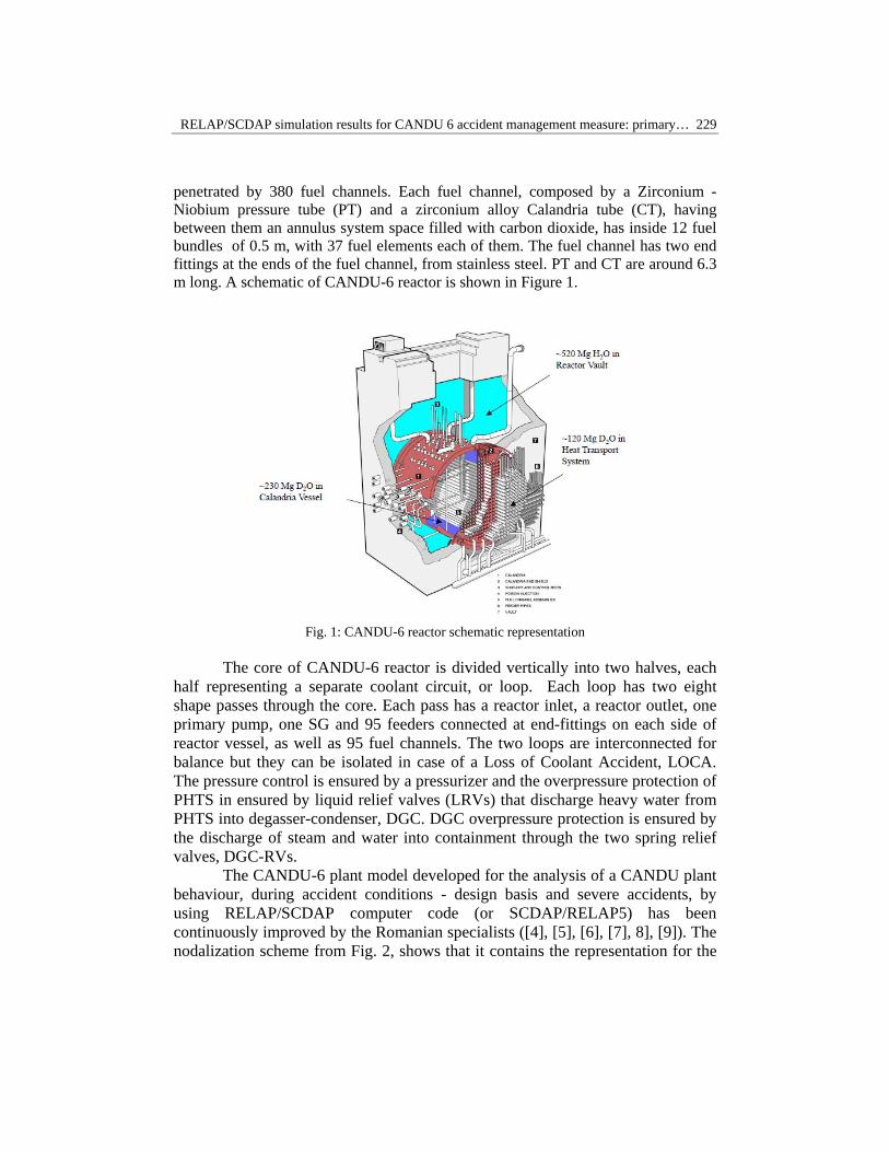
A schematic representation of the CANDU-6 reactor is provided in Figure 1, as well as the CANDU-6 water sources for accident prevention and mitigation.
The moderator system is a separate system from PHTS, containing into CV heavy-water outside the fuel channels, at low temperature and low-pressure. This water inventory, representing an inherent safety characteristic of the CANDU reactors, could play an important role in severe accident prevention and mitigation by passively removing decay heat from the fuel for many hours after an accident. This will ensure a time window large enough for operator intervention. The main accident mitigation measure in case of a SBO event is the depressurization of Steam Generators (SGs) and injection of water into SGs, from Dousing Tank or by Emergency Water System, EWS. SGs depressurization can be done automatically or by the operator but in both cases the Main Steam Safety Valves (MSSVs), that ensure SGs depressurization, have to be blocked in open position in order to have a path for continuous steaming to environment for heat removal. Analyses performed until now showed that SGs represents an efficient seat sink for primary coolant ([12],[14]), even in the cases when this depressurization and water injection into SGs is done late, after SGs dry-out (calculations performed by authors).
Only for the case when SGs can’t be depressurized or there are problems with the injection of water into SGs, the fuel channel rupture can be still precluded for a while, creating the necessary conditions and ensuring a generous time window to implement other accident management measures, as firstly the water injection into PHTS by ECC high and medium pressure stages. These conditions can be realized by the voluntary depressurization of the PHTS (VD-PHTS) using two depressurization valves, for redundancy, special installed on the primary circuit. The location, size and moment of these voluntary depressurization valves (VDVs) of PHTS, are subjects of sensitivities studies.
The paper presents the analysis of the consequences of the severe accident resulted from the unmitigated station blackout (SBO) event and the case when the depressurization of the primary circuit is performed, before the fuel channels rupture, in order to keep the reactor core integrity and to create provide conditions and time for water injections into PHTS. Three different cases have been analysed for VD-PHTS, as a sensitivity study, in order to determine the period to implement such accident management measure. The RELAP/SCDAP Mod 3.6 code ([1], [2], [3],[13]) was used for this severe accident analysis.
2. CANDU-6 plant models
CANDU-6 reactor is a Canadian designed Pressurized Heavy Water Reactor (PHWR) type, having a gross capacity of about 700 MW(e), using heavy water both for moderator and for primary coolant, in separate circuits, and natural uranium for fuel. CANDU-6 reactor consists in a large Calandria Vessel (CV), as reactor vessel,
RELAP/SCDAP simulation results for CANDU 6 accident management measure: primary… 229
penetrated by 380 fuel channels. Each fuel channel, composed by a Zirconium - Niobium pressure tube (PT) and a zirconium alloy Calandria tube (CT), having between them an annulus system space filled with carbon dioxide, has inside 12 fuel bundles of 0.5 m, with 37 fuel elements each of them. The fuel channel has two end fittings at the ends of the fuel channel, from stainless steel. PT and CT are around 6.3 m long. A schematic of CANDU-6 reactor is shown in Figure 1.
Fig. 1: CANDU-6 reactor schematic representation
The core of CANDU-6 reactor is divided vertically into two halves, each
half representing a separate coolant circuit, or loop. Each loop has two eight shape passes through the core. Each pass has a reactor inlet, a reactor outlet, one primary pump, one SG and 95 feeders connected at end-fittings on each side of reactor vessel, as well as 95 fuel channels. The two loops are interconnected for balance but they can be isolated in case of a Loss of Coolant Accident, LOCA. The pressure control is ensured by a pressurizer and the overpressure protection of PHTS in ensured by liquid relief valves (LRVs) that discharge heavy water from PHTS into degasser-condenser, DGC. DGC overpressure protection is ensured by the discharge of steam and water into containment through the two spring relief valves, DGC-RVs.
The CANDU-6 plant model developed for the analysis of a CANDU plant behaviour, during accident conditions - design basis and severe accidents, by using RELAP/SCDAP computer code (or SCDAP/RELAP5) has been continuously improved by the Romanian specialists ([4], [5], [6], [7], 8], [9]). The nodalization scheme from Fig. 2, shows that it contains the representation for the

230 Elena Dinca, Daniel Dupleac, Ilie Prisecaru
two loops with fuel channels, inlet headers, feeders and end fittings, outlet headers, feeders and end fittings, primary coolant pumps, pressurizer, steam generators and associated pipes. A simplified model for balance of plant systems is also used in analysis.
Fig. 2: CANDU-6 – PHTS nodalization scheme
RELAP/SCDAPSIM has been designed to describe the overall primary heat transport system thermalhydraulic response and core behavior under normal operating conditions or under design basis or severe accident conditions. The RELAP5 models calculate the overall PHTS thermalhydraulic response, control system behavior, reactor kinetics, and the behavior of special reactor system components such as valves and pumps. The SCDAP models calculate the behaviour of the core and vessel structures under normal and accident conditions [13]. The models calculate the progression of damage in the reactor core: heat-up,

RELAP/SCDAP simulation results for CANDU 6 accident management measure: primary… 231
oxidation and meltdown of fuel rods and control rods, ballooning and rupture of fuel rod cladding, release of fission products from fuel rods and disintegration of fuel rods into porous debris and molten material. More versions of RELAP/SCDAP code have been release, the most common being the commercial version Mod3.4. Some of the PHWR characteristics could not be correctly represented when using the version RELAP/SCDAPSIM/Mod3.4. Mod3.5 contains important improvements, comparing with the previous Mod3.4 version, which were specifically added to improve the modelling of out-of-pile fuel rod experiments and to improve the modelling of fuel rod behaviour during reactor accidents. Several code extensions were introduced to RELAP/SCDAPSIM/Mod3.5, which was identified as Mod3.6 after including new ATUCHA and CANDU specific features [13]. All simulated CANDU-6 plant components are modelled using RELAP5 components, excepting the fuel and fuel channel thermal response that are modelled using SCDAP components. A detailed description of RELAP/SCDAP model of CANDU-6 plant, the analysis methodology, assumptions and failure criteria used in analysis of SBO can be found in Ref. [5], [7], [8], [10].
CANDU-6 reactor is modelled both with RELAP5 and SCDAP components, in this SBO simulation. CV is modelled as two parallel pipe components with three vertical sub-volumes. Each of these pipe components simulates half of the CV volume and represents the moderator surrounding fuel channels of one PHTS loop. The analogous volumes of the two parallel pipes are connected through cross flow junctions, as it is shown in Figure 3, representing the CV model used in analysis.
Fig. 3: Calandria Vessel model

232 Elena Dinca, Daniel Dupleac, Ilie Prisecaru
The four CV pressure relief ducts are modelled as a single pipe component with three sub- volumes having vertical orientation. The over pressure protection of CV is ensured by the break of the rupture disks (CV-OPRD), that are modelled as a single trip valve that connects CV with reactor containment.
3. SBO analysis conditions
For the purpose of this paper, the SBO analysis is carried out until the core collapse occurs, for the case without credit for any heat sink or mitigation measure. The behaviour of the debris on the bottom of CV, the behaviour of the molten pool or CV were not considered. Also, the containment behaviour as a result of steam and water discharge from PHTS, CV or other pressurization sources has not been analyzed here.
Two sets of analyses have been performed for this study. First, Case A, was represented by the case of SBO at CANDU, without credited for any heat sink for the nuclear fuel (reference case). This case was analyzed many times until now, using different computer codes and models (MAAP-CANDU, ISAAC, SCDAP/RELAAP5), [10], [11], [12]. The reason of the new study was to analyse all cases using the same Mod3.6 version of RELAP/SCDAP (having CANDU specific features) and the same models and input data (including a complex model of the reactor core with 32 SCDAP components). The analysis results of this reference case are used for comparison with the results obtained for cases with voluntary depressurization (VD-PHTS).
For the second part of the study, in order to fulfil the objectives of this analysis, the PHTS model was slightly modified. Two depressurization valves (VDVs) were added to ensure the primary circuit depressurization before the fuel channel rupture. This PHTS new depressurization feature was proposed only for study, to determine the opening of VDVs at a selected moment can ensure, using another way than the fuel channel break, the necessary conditions to inject water into PHTS, in case the SGs couldn’t be depressurized or/and water into SGs couldn’t be supplied. For this analysis purpose, the two valves have been considered located on the line to the degasser condenser, before the branch to Liquid Relief Valves, as is indicated in Figure 4. Regarding the size of these valves, the same total area of discharge has been considered in the input model, as for the rupturing of 10 fuel channels (the assumption considered in [10]), 0.03475 m2.
For High and Medium Pressure ECC injection into PHTS it is necessary to have basically the PHTS pressure lower than ECC pressure injection and a path for hot water or/and steam discharge into containment. These conditions for HPECC and MPECC injection into PHTS can be created by the VDVs opening. First, this ensures the PHTS depressurization and the open valves ensure a path

RELAP/SCDAP simulation results for CANDU 6 accident management measure: primary… 233
for fluids discharge from PHTS (to avoid re-pressurization of PHTS). The necessary water in the sump is ensured by the dousing spray, when the containment pressure increases over a setpoint (due to RVs and VDV’s discharge), as well as by the PHTS inventory discharged into containment, both through the overpressure protection valves (LRVs, RVs) and through open VDVs.
In addition, for Low Pressure stage of ECC (LPECC) action, it is necessary to have enough water in the sump, one LPECC pump available and also service water provided to the ECC heat exchanger. The LPECC pump could be supplied with electrical power in case of SBO using for example mobile Diesel generators (MDG), that should be available after 2,5-3 hours from SBO initiation, according to [14]. MDG can also ensure the operation of the service water pumps. If, after 3 hours from the initiation of the SBO, SGs couldn’t be depressurized or water into SGs couldn’t be injected, a PHTS depressurization might be done by opening (operator action) the voluntary depressurization valves (VDVs). VDVs would need to have independent sources of power and/instrument air for valves actuation.
Fig. 4: The CANDU-6 reactor – PHTS depressurization model

234 Elena Dinca, Daniel Dupleac, Ilie Prisecaru
Three different cases, CaseB1, B2 and B3, have been analyzed for SBO with VD-PHTS: at 2.5 h (9000s), 3h (10800s) and 3.5h (12600s) after an SBO and no other accident management measures considered before. The simulations have been done for about 40,000s each, except the depressurization at 9000s (this was done only for 21000s), as the latest case is considered to have the PHTS depressurization too early. This study didn’t simulate the ECC water injection into the channels. It only determined the differences in the accident progression caused by the depressurization and highlighted the opportunities created to implement mitigation actions and to maintain the integrity of the core, as well as the impact on CV and containment (in terms of pressure and flow discharged).
Different analysis assumption and failure criteria were used in analysis, the same as in [10], as these have been agreed by the users that analyzed SBO to CANDU using different computer codes. A temperature criterion of 1000K on the inner pressure tube is considered for the fuel channel failure, when the channel pressure is higher than 1 MPa and a temperature of 1473K on the CT is considered for fuel channel disassembly when pressure is lower than 1 MPa.
4. Analysis results
In the reference case (Case A), as a result of loss of power, SGs will ensure the heat sink until their dry-out. First SG will dry-out at 7360s and the last one at 7510s (Fig.5).
Fig. 5: SBO event at CANDU-6: SGs level
After SGs are lost as heat sink, the PHTS pressure will increase and at
8580s first LRV will open and discharge heavy water into degasser-condenser, DGC. All LRVs will open and close near their setpoints of 10.24 MPa(g) to ensure PHTS overpressure protection. When DGC pressure increase at 10.16 MPa, the two RVs open, first time at 9150s, and then they will cycle for DGC

RELAP/SCDAP simulation results for CANDU 6 accident management measure: primary… 235
overpressure protection. As a result of this discharge, PHTS inventory decreases gradually, as it can be seen in Fig. 6. The same figure shows the evolution of the PHTS inventory in Cases B, with VD-PHTS at different moments.
Fig. 6: SBO event at CANDU-6: PHTS inventory
In Case A, at 12960s, first fuel channels break and determine PHTS de-
pressurization. The PT and CT rupture determine a rapid blow-down from the PHTS into the CV. Moderator pressure will increase suddenly due to PHTS inventory discharged into CV and determine the break of the CV ducts rupture disks. A large amount of moderator is expulsed through the ruptured disks and as a consequence, a rapid decrease in the CV water level occurs. The fuel channels at the upper side of CV become uncovered and start to heat-up, as the fuel channels located on the lower side of CV are still submerged in water. After the initial rapid moderator expulsion, the moderator continues to discharge gradually into the containment, as a result of continued moderator boil-off, due to the heat transfer from the core. According to [9], [10], [11], [12], [13], this behaviour resulted from all analyses performed, even if there are differences in terms of timing or parameters values. The uncovered fuel channels heat-up, sag and disassembly when temperature increase over 1473K.
For the purpose of this paper the moment when first time one fuel channel break in the core in case of SBO is considered as the end of the period when the core geometry can be still maintained and the severe accident remains a limited core-damaged accident, in all analyzed cases. For the reference case this moment is at 12960s, when 10 channels (assumption, according to [10]) break, at high pressure, and possibly challenge the CV. By comparison, in Cases B the behaviour is similar with Case A until the moment of voluntary depressurization of PHTS. In Case B3, VDVs open at 12600s and discharge the remained PHTS inventory into containment. The maximum flow rate discharged through VDVs is about 440 kg/s (total, for both valves), and decreases at less than 1kg/s in around

236 Elena Dinca, Daniel Dupleac, Ilie Prisecaru
250s. PHTS pressure decreases rapidly, under 1MPa, in about 90 s. For Case B2 the total flow rate is 680 kg/s and for Case B1 (at 9000s), the total flow rate is 1114 kg/s.
After PHTS depressurization, fuel temperature decreases also for a while. HPECC and MPECC can inject water in the fuel channels and cool the fuel. There is a criterion for re-flooding of the core; this can be done if the cladding temperature is less than 1000°C (1273K). It is considered as a time window for operator to inject water into the channels the period between the PHTS depressurization and the moment when the maximum fuel surface temperature reaches 1273K. For Case B3 this temperature is reached at 15960 s, so the time window to reflood the fuel channels is of 3360s. Fig. 7 shows the evolution of the maximum fuel surface temperature for Case A and Case B3, for comparison.
Fig. 7: SBO at CANDU-6: Maximum fuel surface temperature (Case A and Case B3)
The time windows that operators have got to implement accident
management measures, in terms of injection of water in channels for the other Cases B are: 3640s for Case B2 and 3800s for Case B1. Fig.8 shows the evolution of the maximum fuel surface temperature in Cases B1, 2, 3.
If no water is injected into channels in the time window mentioned above, the temperature of the fuel will increase and finally the fuel channels disassembly, by sagging, as in the reference case. Before this, hot channels will transfer heat to the moderator and will determine the CV pressurization that leads to the break of CV rupture disks. The pressure impact on CV and also the moderator flow discharged into containment are sensible less than in Case A. Fig.9 shows the pressure in the CV in cases with and without VD-PHTS (Case B3 and A). Fig.10 shows the moderator flow discharged into containment in Case A and Case B3, for comparison.

RELAP/SCDAP simulation results for CANDU 6 accident management measure: primary… 237
Fig. 8: SBO at CANDU-6: Maximum fuel surface temperature (Case B1,2,3)
Fig. 9: SBO at CANDU-6: CV pressure (Case A and Case B3)
Fig. 10: SBO at CANDU-6: Moderator flow discharged into containment (Case A and Case B3)

238 Elena Dinca, Daniel Dupleac, Ilie Prisecaru
Moderator level decreases in all cases, due to continuous vaporization, proportional with heat transferred from the hot fuel channels.
Fig. . SBO event at CANDU-6: Evolution of moderator level (Case A and Cases B1,2,3)
Regarding the sensitivity study performed for VD-PHTS, Cases B, it can
be mentioned: - In Case B3, the moment of VD-PHTS is very close of the moment of
channel rupture under pressure (Case A), but it is still efficient, cooling for a while the fuel and creating a good time window for ECC injection.
- In Case B2, VD-PHTS at 3 hours from SBO initiation seems to be far enough from the moment of channel rupture (of Case A), the maximum flow discharged through VDVs is not so high and there is 1 hour period of time to implement accident management measures in order to preserve the core geometry.
- Case B1, by comparison with B2 and B3 brings a larger time windows for operator actions to inject water into PHWR, but almost whole PHWR is discharged fast into containment, like in a large LOCA, leading probable to a negative impact on the containment.
Total mass of hydrogen generated by oxidation is shown in Fig.11 for all analyzed cases, for the reference case and for VD-PHTS, without ECC injection.

RELAP/SCDAP simulation results for CANDU 6 accident management measure: primary… 239
Fig.11: SBO event at CANDU-6: Integrated mass of H2 generated (Case A and Cases B1,2,3)
5. Conclusions
The RELAP/SCDAPSIM/Mod 3.6 code ([1], [2], [3], [13]) was used to perform the analysis of the consequences of a SBO event at a CANDU-6 plant, with and without voluntary depressurization (VD) of the PHTS. The VD-PHTS is not possible at the actual CANDU-6 project, Voluntary Depressurization Valves being considered only for this study. The VD-PHTS is performed only in case SGs couldn’t be depressurized and water injected into SGs.
The main results of this study can be summarized as it follows: − The behaviour of the plant in the first part of the event is the same for all
cases, until the VD-PHTS; this action being performed by the operator, before any fuel channel to break. In particular, the SGs are dry at the same moments, and LRVs and DGC-RVs open and discharge fluids from PHTS in the same manner.
− After the VD-PHTS, the core heating is delayed, and fuel channels break under pressure will not occur, which will avoid high CV pressurization and high moderator flow into containment.
− The channels disassembly due to continuous heating is also delayed comparing with reference case, and a time window of about 1 hour is created, between the VD-PHTS and the end of the period in which water can be still added into channels, using ECC.
− In cases with VD-PHTS, the highest mass flow rate (Case B1) discharged into containment through VDVs is 1114 kg/s, whish is much lower than the moderator flow discharged at the CV rupture disks break in Case A, of 13905.4 kg/s, more than ten times.
− Integrated mass of hydrogen generated is not higher, per total, in case of VD-PHTS than in the reference case.

240 Elena Dinca, Daniel Dupleac, Ilie Prisecaru
The most important conclusion is that by voluntary depressurization of the primary circuit, at about 3 hours after SBO initiation - only in case SGs do not act as a heat sink, the energetic rupture (under pressure) of the fuel channel can be precluded, creating in the same time the necessary conditions for ECC water injection in the core, action that can be done in about 1 hour.
R E F E R E N C E S
[1]. SCDAP/RELAP5 Development Team SCDAP/RELAP5/MOD3.2 Code Manual, Vol. 1-5, NUREG/CR-6150, INEL-96/0422, Rev.1, 1997.
[2]. C. M. Allison, J. K Hohorst. Role of RELAP/SCDAPSIM in Nuclear Safety, TOPSAFE, Dubrovnik, Croatia. September 30-October 3, 2008
[3]. L. J. Siefken, C. M. Allison, J. K. Hohorst, RELAP/SCDAPSIM/MOD3.5 - Improvements Resulting from QUENCH and PARAMETER Bundle Heating and Quenching Experiments, ISS, USA, 2010.
[4]. G. Negut, I. Prisecaru, A. Catana. CANDU 600 severe accident assessment. In: Proceedings of the 16th International Conference on Nuclear Engineering - ICONE16, Orlando, May 11-15, 2008, VOL 3, Pag.: 477-484, 2008.
[5]. D. Dupleac, M. Mladin, and I. Prisecaru. Generic CANDU 6 plant severe accident analysis employing SCAPSIM/RELAP5 code, Nuclear Engineering and Design, 239, 2093–2103, 2009.
[6]. D. Dupleac, M. Mladin, and I. Prisecaru. SCDAP/RELAP5 analysis of progression of severe accident in CANDU 6. In: Proceedings of the 17th International Conference on Nuclear Engineering- ICONE17, Brussels, Vol. 3 Pag.: 47-57, 2009.
[7]. M. Mladin, D. Dupleac and I. Prisecaru. Modifications in SCDAP code for early phase degradation in a CANDU fuel channel. In: Annals of Nuclear Energy, Volume: 36, Issue: 5 Pag.: 634-640, May 15, 2009.
[8]. G. Negut, A. Catana, I. Prisecaru, Severe accident development modeling and evaluation for CANDU, Annals of Nuclear Energy, Volume 36 Issue: 9 Pages: 1424-1430, September 2009
[9]. A. Budu, D. Dupleac, Pressure tube oxidation heat addition in an accident in a CANDU type nuclear power plant, U.P.B. Sci. Bull., Series C, Vol. 73, Iss. 2, Bucharest, 2011.
[10]. IAEA TECDOC SERIES, TECDOC No. 1727- Benchmarking Severe Accident Computer Codes for Heavy Water Reactor Applications, International Atomic Energy Agency, Vienna, 2013.
[11]. T. Nitheanandan et al., Backup and Ultimate Heat Sinks in CANDU Reactors for Prolonged SBO Accidents, Nuclear Engineering and Technology, Vol.45, No.5., 2013.
[12]. S.M. Petoukhov, MAAP4-CANDU simulation results for CANDU 6 accident management measure: steam generator secondary side water make-up from dousing tank for the station blackout scenario”, The 19th Pacific Basin Nuclear Conference (PBNC 2014), Vancouver, British Columbia, Canada, 2014.
[13]. A.Bonelli, O.Mazzantini, D.Dupleac, E.Dinca, L. J. Siefken, C. M. Allison, J. K. Hohorst „RELAP/SCDAPSIM/MOD3.6 – Development of Severe Accident Models for Heavy Water Reactors Including CANDU and Atucha-2”. I. Proc. ICAPP 2015, May 03-06, Nice, France, (Paper 15080), (2015).
[14]. CNCAN, „National Report on the Implementation of the Stress Tests”, Bucharest, December 2011.