rel 511 c*2 - abb group · rel 511 c*2.0 1 mak 506 024-ben page 1 ... start function, ... the...
TRANSCRIPT

REL 511 C*2.0
1 MAK 506 024-BENPage 1
Issued Apri/1999Status: New
ecllo change withoui noliceData subj
(SE 95 02 07)
Features .Line distance functionality comprises;
-simultaneous measurement of the differ-ent phase. phase and phase. earthimpedances with numerical measuringelements, ilndividually for each type offault and each distance zone for fast andreliable fault detection
-three zone protection with completelyindividual settings
-separate and independent impedancemeasuring elements for the GeneralFault Criteria with advanced characteris-tic
-scheme communication logic with cur-rent reversal and weak end infeed logics
-power swing detection
.Additional protection functions includedsuch as;
-phase overl~urrent, residual current
-breaker faillJre protection
-fuse failure and current transformercircuit supervision
-single- or mlulti-pole tripping
.Controi functions included:
-autoreclosing and synchro-check withenergising (~heck
.Monitoring functions included:
-event recorljer
-disturbance recorder
Compact line distance protection terminal REL 511 C*2.0
General Substation Monitoring System (SMS) andSubstation Controi System (SCS). The unitsin the PANORAMA concept are available asstand alone relays/terminals or as buildingblocks in a total power network managementsystem.
The REL511 C line distance protection ter-minal is one of the basic units for distributionand sub-transmission line distance protectionapplications and forms a part of a PAN-ORAMA Station Automation.
The PANORAMA ,Station Automation con-cept includes a complete range of single-function units and multi-functional terminals,
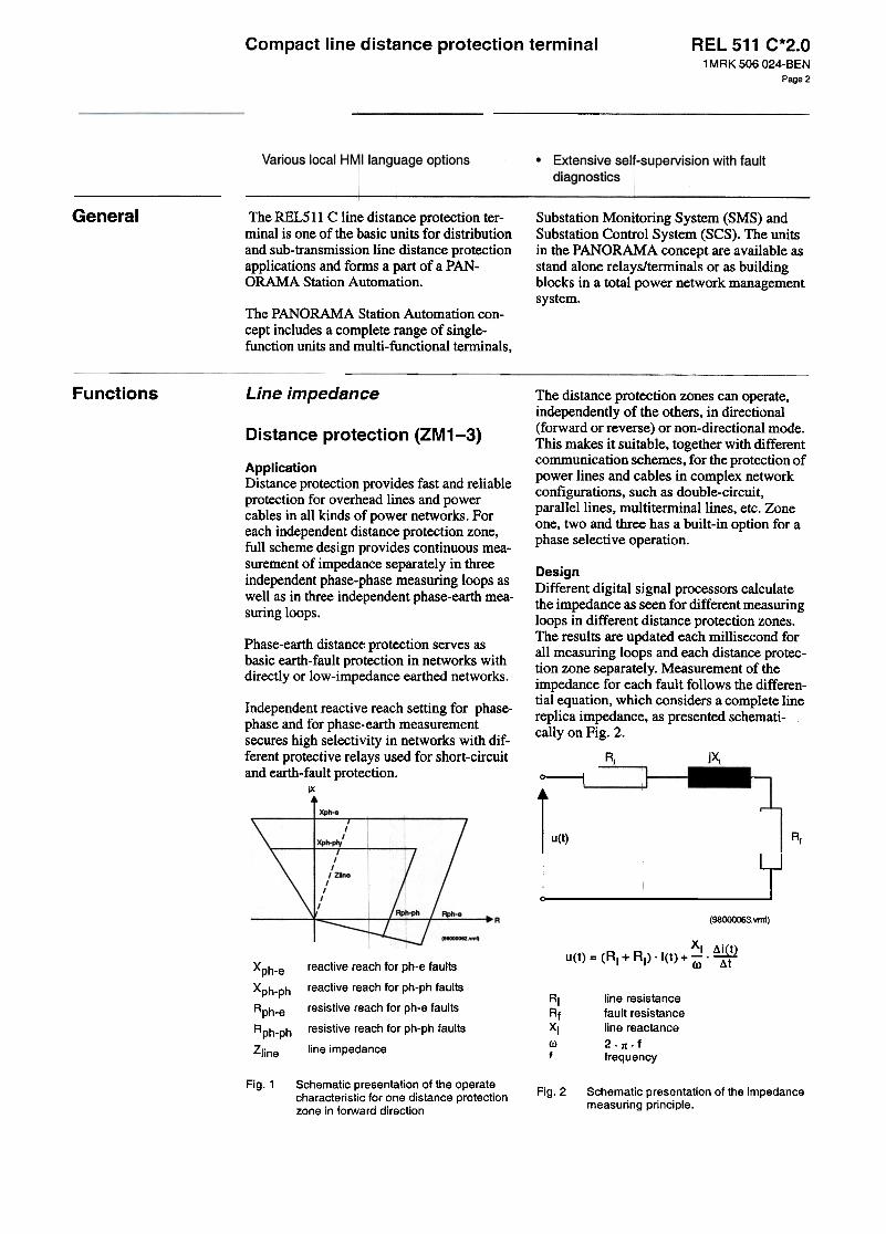
Functions Line impedance The distance protection zones can operate,independently of the others, in directional(forward or reverse) or non-directional mode.This makes it suitable, together with differentcommunication schemes, for the protection ofpower lines and cables in complex networkconfigurations, such as double-circuit,parallellines, multi terminal lines, etc. ZoneoDe, two and three has a built-in option for aphase selective operation.
Distance prot4~ction (ZM1-3)
ApplicationDistance protection provides fast and reliableprotection for overhead lines and powercables in all kinds of power networks. Foreach independent distance protection zone,full scheme design provides continuous mea-surement of impedance separately in threeindependent phase-phase measuring loops asweIl as in three independent phase-earth mea-suring loops.
DesignDifferent digital signal processors calculatethe impedance as seen for different measuringloops in different distance protection zones.The results are updated each millisecond forall measuring loops and each distance protec-tian zone separately. Measurement of theimpedance for each fault föllows the differen-tial equation, which considers a complete linereplica impedance, as presented schemati-cally on Fig. 2.
Phase-earth distance protection serves asbasic earth-fault protection in networks withdirectly or low-impedance earthed networks.
Independent reactive reach setting for phase-phase and for phase-earth measurementsecures high selectivity in networks with dif-ferent protective relays used for short-circuitand earth-fault protection.
IX
RI jx,
"---i
u(t)
i(t) ..
~
L,J~ ! I
(98000063. vmf)
u(t) = (RI + Rf) .i(t) + ~ .~(J) ~treactive rea ch for ph-e faults
reactive reach for ph-ph faults
resistive reach for ph-e faulls
resistive reach for ph-ph faults
line impedance
Xph-e
Xph-ph
Rph-e
Rph-ph
Zline
RIRfXIrof
line resistancefault resistanceline reactance
2.n.ffrequency
Fig. 1 Schematic presentation of the operatecharacteristic for one distance protectionzone in forward direction
Fig.2 Schematic presentation of the impedancemeasuring principle.
1 MAK 506 024-BENPage 2

Compact line distance protection terminal REL 511 C*2.0
Setting of all line parameters, such as positivesequence resistance and reactance as weIl aszero-sequence resistance and reac-tance,together with expected fallit resistancefor phase-phase and phase-earth faults, areindependent for each zone. The operate char-acteristic is thus automaticaIly adjusted to theline characteristic angle. The earth-returncompensation factor for the earth- fallit dis-tance protection is calculated automaticaIlyby the terminal itself.
Voltage polarisation for directional measure-ment uses continuous calculation and updat-ing of the positive sequence voltage for eachmeasuring loop separately. This secures cor-rect directionality of the protection on differ-ent evolving faults within the complexnetwork configurations. Positive-sequencememory voltage secures reliable directionaloperation on close-up three-phase fallIts.
Xfw
Xrv
Af
Rid
ARGld
Reactive reach in forward direction
Reactive reach in reverse direction
Resistive reach related to faultresistance
Resistive reach related to minimumload impedance
Load impedance angleThe distance pcc)tection function blocks areindependent of each other for each zone.Each function block comprises a number ofdifferent functional inputs and outputs, whichare freely configurable to different externatfunctions, logic gates, timers and binaryinputs and outputs. This makes it possible toinfluence the operation of the complete mea-suring zone oronly its trip function by theoperation of the fuse-failure function, thepower-swing-detection function, etc.
Fig.3 General fault criteria -schematic presen-tation of the operate characteristic in the
impedance plane
Independent measurement for each fault loopsecures reliable phase selection and correctoperation for complex network faults, such assimultaneous faults on paralIeI circuits,evolving faults, etc. Independent reactivereach setting for phase-phase and for phase-earth measurement secures high selectivity innetworks with different protective relays osedfor short-circuit and earth-fault protection.
General faullt criteria (GFC)
ApplicationThe general fault criteria is an independentimpedance measuring function, which servesas an overall fault detection and/or phaseselection element in all kinds of networks.Observe that the GFC function is not used asstart function, because full scheme measure-ment is utilised for the distance protectionzones.
DesignThe basic operate principle is the same as forthe basic distance protection zones (seeFig. 2). 1t is possible to set the reactive reachin forward and reverse direction for phase-phase and for phase-earth measurement sepa-ratelyand independently of each other. Set-ting of the resisti ve reach can also be differentfor phase-phase and for phase-earth measure-ment.
The GFC function is specially suitable incases when the fallit resistance to be detectedexceeds the minimum expected load imped-ance. The shaped operate characteristic in theimpedance plane (see Fig. 3) prevents theoperation of the irnpedance measuring ele-ments for low loRd impedances and at thesame time allows coverage of higher fallitresistance with remote infeed of the fallitcurrent.
The usel can program the influence of theGFC function on the operation of the distanceprotection zones used. The GFC function canprevent the operation of the distance protec-tion zones with a Teach longer than the Teachof the GFC elements, as long as the measuredimpedance is outside the GFC operate charac-teristic.
1MRK 506 024-BENPage 3

Compact line distance protection terminal REL 511 C*2.0
Functions (cont'd) Current reversal and weak endinfeed logics (ZCAL)
Operation of the distance protection zonescan also be completely independent on theoperation of the GFC function.
Power swing detection (PSD)ApplicationThis function is a complement to the ZCOMor to the ZCIP function.
In interconnected systems, the fault currentcan change direction when circuit breakersopen to clear the fallit. The permissive over-Teach scheme should have a current reversallogic which. when activated, will preventunwanted operation in case of current rever-sal.
ApplicationThe power swing detection function detectspower swings with a periodic swing time aslow as 200 ms (i.e. slip frequency as high as10% of the rated frequency on a 50 Hz basis).It detects swings under normal system condi.tians as weIl as during the dead-time of thesingle-pole reclosing cycle.
If the infeed of the fault current at the remoteend is too low to operate the forward directedmeasuring element, no carrier signal will beobtained from the remote end when there is afault on the line and the communicationscheme will not operate properly. This will bethe cage if the zero sequence source at theremote line end is too high, e.g. if the line cir-cuit breaker is open. The permissive commu-nication scheme should therefore include aweak end infeed logic which, when activated,reflects the carrier signal and thereby securestripping. It can also be used to trip the localcircuit breaker in cages when fault currentdistribution prevent carrier signal.
DesignThe operation of the PSD function is basedon the measurement of the transition time thatthe power swing transient impedance needs topass the impedance area between two imped-ance measuring characteristics (known as l1ZJA-t measurement). The impedance measuringprinciple is the same as the one used for thedistance protection zones (see Fig. 2). Thetransient impedance time is measured in allthree phases separatelyand one-out-of-threeor two-out-of-three operating modes can beselected permanentlyor according to the spe-cific system operate conditions.
The use of different timers for initial and con-secutive swings secures a high degree of dif-ferentiation between power swing and faultconditions. Built-in logic circuits and config-urable functional inputs makes it possible tocombine the function with other functionsand conditions, as weIl as to use it in the sameway as with older distance relays.
Autamatic switch anta faultlagic (SOTF)
ApplicationThe switch-onto-fault protection secureshigh-speed operation of the distance protec-tion on energising of faulty or short-circuited (earthed for safety reasons) powerlines. Two operating modes are available forthe detection of a breaker closing condition:Use of an auxiliary contact from a line CBcontroi switch or the operation of a built-indead-line-detection (DLD) function. The sec-ond mode is highly recommended for busbarconfigurations where more than one circuitbreaker can energise the protected line at oneline end.
Scheme comlTlunication logic(ZCOM)
ApplicationTo achieve fast fallit clearing for a fallit on thepart of the line not covered by the instanta-neous zone 1, the stepped distance protectionfunction can be supported with logic, utilisingcommunication channels. One communica-tion channel, capable of transmitting an 00/off signal, is required in each direction. Design
The function is active for Olle second arter thebreaker cIosing conditions have been reportedby the external auxiliary contact or by theDLD function (automatic mode). The outputsignal will be generated if the fauIt has beendetected within the non-directional Teach ofthe selected distance protection zone. Config-urable function inputs and outputs make itpossibIe to configure different use of the
Depending on whether a reverse or forwarddirected impedance zone is used to issue theseDd signal, the communication schemes aredivided in 'Blocking' and 'Permissive'schemes, respectively. This function cansupport any scheme communication require-ments.
1 MRK 506 024-BENPage 4

Compact line distance protection terminal REL 511 C*2.0
Breaker failure protection (BFP)function. Note: The presence of the dead-line-detection function is absolutelyrequired, if the function shall operate in theautomatic mode"
ApplicationThe breaker failure protection provides back-up protection in cage of failure of the breakerto trip and clear the fault as requested by theobject protection. It is obtained by checkingthat fault current persists af ter a brief timefrom the opemtion of the object protection.
Current, phase wise
InstantaneOlus phase over-current projtection (IOC)
DesignThe breaker failure protection is initiated bythe trip commands from the protection func-tions, either imternal to the terminal or fromexternat commands thrOUgh binary inputs.The start can be single-phase or three-phase.
ApplicationDifferent system! conditions, such as sourceimpedance and the position of the faults onlong transmission lines, infIuence the faultcurrents to a gre:lt extent. The IOC function,with low overreaching of the measuring ele-ments, secure very short operate times, downto 10 ms and sell~tive tripping for close-infaults on long power lines, where short faultclearing times are extremely important inmaintaining system stability
The operate valnes of the three current mea-suring elements are settable within a widesetting range. The measurement is stabilisedagainst the dc~transient that can causeunwanted operation with saturated currenttransformers. Time measurement is individ-ual for each phase. Two independent timersare available, Tl for repeated tripping of'own' breaker and T2 which operates triplogic for adjacent breakers.
DesignThe IOC function comprises a three phaseinstantaneous overcurrent protection. Whensingle-pole tripping is required, the singleand/or three-pol(: trip logic allows for phaseselective starting; signals from the function. Current, residual (earth (ault)
Time delaYE!d phase over-current pro1:ection (TOC)
Current residual
ApplicationIn case of single-ph ase to earth faults, theprimary fallit resistance will vary with thenetwork conditions and location of the fault.In many cases the fallit resistance is muchhigher than the resistance that can be coveredby an impeda11lce measuring distance func-tian.
ApplicationThe time-delayed overcurrent protectionoperates in different system conditions forcurrents exceeding the pre-set value andremain high for langer than the delay time seton the corresponding timer. The function canalso be used as slLlpervision and fault detectorfor same other protection functions, toincrease the security of a complete protectionsystem. It can seJrve as a reserve function forthe line distance Iprotection, if activated underfuse failure conditions which disables theoperation of the line distance protection.
Earth faults with high fault resistance can bedetected by measuring the residual current(310). Hence, the current residual functionscan be osed as complement to the impedancemeasuring distance function for sensitiveearth fault detection.
DesignThe TOC function comprises a three phasetime-delayed overcurrent protection. Phaseselective starting signals are available fromthe function.
To prevent unwanted operation when energis-ing a directly grounded power trans former,the functions are provided with 2nd harmonicrestraint blocking feature.
The inverse time delayed function is providedwith minimum operate current and minimumoperate time for improved selectivity in cer-tain applications.
1 MAK 506 024-BEN
Page 5

REL 511 C*2.0Compact line distance protection terminal
Functions (cont'd) The instantaneous and time-delayed functionscan be made directional together with logicsfor communication scheme cooperation,weak-end-infeed and current reversal.
function is supervised by the fuse-failurefunction and the information about the closedposition of an associated circuit breaker.
Overload supervision (OVLD)DesignFollowing current residual functions areselectable; Application
The overload protection prevents excessiveloading of power lines. Its operation is basedon the measurement of the maximum phasecurrent and its duration, which must notexceed the pre-set values. The operate currentand the operate time are settable within awide range.
1. Instantaneous
2. Time delayed;
-Independent time delay
3. Inverse time delayed;
-Normal inverse (NI)
-Very inverse. (VI)
-Extremely inverse (El)
-Logarithmic inverse (IDG)
NI. VI and El according to mc 255-3
Secondary system supervision
Fuse failure supervision (FUSE)
ApplicationThe fuse-failure-supervision function contin-uously supervises the ac voltage measuringcircuits between the voltage transformers andthe terminal. Different output signals can beused to block, in the case of faults in the acvoltage secondary circuits, the operation ofthe distance protection and other voltage-dependent functions, such as the synchro-check function, the undervoltage protectionfunction, etc.
4. Directional check and communicationschemes
Power system supervision
Broken conductor check (BRC)
ApplicationThe broken-conductor check function detectsnon-symmetrical current conditions in thethree phases. The BRC function is especiallysuitable for the detection of broken conduc-tOfS on protected power lines and cables(series faults) without the presence of theadditional short circuits (phase-earth orphase-phase fallits). It will also detect inter-ruptions in secondary current circuits.
Zero-sequence based measurement is recom.mended in directly- or low-impedanceearthed systems.
DesignThe function continuously measures the zero-sequence voltage and current in three-phaseac voltage circuits. It operates if the measuredzero sequence voltage increases over the pre-set operate value, and if the measured zerosequence current remains below the pre-setoperate value.
DesignThe function measures all three-phase cur-rents and operates when the ratio between theminimum of measured phase currents and themaximum phase current falls below the setvalue. The phase current must be higher than20% of the terminal rated current.
Two function output signals are available.The flTst depends directly on the voltage andcurrent measurement. The second depends onthe operation of the dead-line detection func-tion, to prevent unwanted operation of thedistance protection if the line has been de-energised and energised under fuse-failureconditions. A special function input servesthe connection to the auxiliary contact of theMCB (when used), to secure correct opera-tion of the functiQn on simultaneous interrup-tion of all three measured phase voltages.
Loss of volta~,e check (LOV)
ApplicationThe loss-of-voltage function is suitable foruse in networks with automatic restorationfunction. The LOV function initiates a three-pole tripping of a circuit breaker. if all threephase voltages fall below the set value forlonger than 7 seconds. The operation of the
1MRK 506 024-BENPage 6

REL 511 C*2.0Compact line distance protection terminal
LogicControi
Synchro-l~heck and energisingcheck (S"NX)
Single- or two-pole tri p logic(TRIP)
ApplicationTRIP operates in singIe-poIe trip mode forsingIe-phase fallIts, in two-poIe operatingmode for two-phase faults (with or withoutearth) and in three-poIe trip mode for three-phase fallIts. It is aIso possibIe to achievethree-poIe tripping for both one-phase andtwo-phase fallIts.
ApplicationThe synchro-check function is used for con-trolled interconnection of a line in an alreadyinterconnected network. When used, thefunction gives an enable signal at satisfactoryvoltage conditions across the breaker that isto be closed. The synchro-check functionmeasures the voltages on the busbar side andthe line side. It operates and permits closingof the circuit-breaker when the set conditionsare met, with respect to the voltage difference(UDiff), the phase-angle difference (phaseDiff),and the frequency difference (FreqDiff)'
The function is applicable for all terminalswhich have built-in phase selection function-ality and is used in applications where single-pole tripping is required for single-phasefaults due to system stability reasons. Thetwo-pole operating mode can be osed ondouble-circuit parallellines with single-polebreakers.
The energising condition can be set to allowenergising in one, or the other, or both direc-tions, e.g. live busbar and dead line. It is pas-sible to have different energising settings fora manual close command and an autoreclosecommand.
DesignSpecial functional inputs are provided for theinitiation of a single, two and three-pole tripcommand. Decision to initiate outgoing tripsignals in different phases depends on a pres-ence of corresponding phase selective signalson special ly provided functional inputs.Additionallogic circuits secure a three-polefinal trip command in the absence of therequired phase selection signals.
DesignThe synchro-check for double busbararrangements includes the voltage selectionfunction. From the auxiliary contacts of thebreakers and disconnectors, the terminal canselect the right voltage for the synchronismand energising function. The function is alsodesigned to allow manual closing when bothsides of the breaker are dead. The function is equipped with logic circuits,
which secure correct operation on evolvingfaults as weIl as arter the reclosing on persis-tent faults. Special function inputs are pro-vided to override the interna! conditions andinitiate an instantaneous three-pole trip com-mand. These inputs could be initiated by dif-recent externa! functions, such as stationbreaker failure protection, transfer trip fromthe remote end line terminal, etc.
Autoreclosiing (ARxx)
ApplicationThe reclosing function can be selected toperform single-, two- and/or three-phasereclosing from eight single-shot or multi-shotreclosing programs. The three-phase auto-reclose open time can be selected to giveeither high-speed autoreclosing or delayedautoreclosing. Three-phase autoreclosing canbe performed with or without the use of thesynchronism check or energising function.
Pole discordance logic,contact based (PD)
ApplicationBreaker pole position discordance can occuron operation of a breaker with independentoperating gears for the three poles. The rea-son may be an interruption in the closing ortrip coil circuit, or a mechanical failure result.ing in a stuck breaker pole. A discordancecaused by one pole failing to close or open
DesignThe autoreclosing function co-operates withthe line protection functions, the trip function,the circuit breaker and the synchro-checkfunction. It can also be influenced by otherprotection functions through binary input sig-nals. The autoreclosing is a logical functionbuilt up by logical elements.
1MRK 506 024-BENPage 7

Compact line distance protection terminal REL 511 C*2.0
Functions (cont'd) can be tolerated for a limited time, forinstance during a single-phase trip-reclosingcycle.
Event recorder (EVA)
ApplicationAn event recording function is available. Itpresents in a IQgical order, starting and trip-ping signals that have occurred in the termi-nal. Up to 150 time-tagged events for each ofthe last 10 recorded disturbances are stored.
Fault locator (FLC)
DesignThe operation of the pole discordance protec-tian is based on checking the position of thebreaker auxiliary contacts. Three paraliei nor-mally-open contacts in series with three nor-mally-closed contacts in paralIei for therespective breaker poles form a condition ofpole discordance, connected to a binary inputdedicated for the purpose. Application
An accurate fault locator is an essential com-plement to the line protection. The faultlocator provides distance to the fault togetherwith information about the measuring loopthat has been used in the calculation. Possi-bility of recalculation with changed para-meter settings exists. Information on the last10 disturbances are available.
Additional configurable logic
ApplicationConfigurable logic is included in basic. Addi-tionallogic circuits including more AND/ORgates are also available. With this logic theuser can configure different logical functionsin the terminals to suit special requirementsfor different applications.
The fault 10cator algorithm compensates theeffect of the 10ad currents, the apparent fauttresistance and rero sequence mutual imped-ance.
Monitoring Trip value recorder (TRVAL)
Disturbance recorder (DR EP) ApplicationInformation on the actual prirnary and secon-darr phasors of the voltages and currents areavailable in the trip value recorder. The pre-fallIt and fallIt values of the applicable volt-ages and currents are recorded with theirphase relations for the last 10 disturbances.
ApplicationThe disturbance recording function is animportant part of a station monitoring system,which enables the evaluation of differentevents within the power system. The high-performance disturbance recorder can memo-rise up to analogue channels and 48 binarysignals (internal signals to the terminal and/orexternai signals connected to the binaryinputs of the terminal). Any of the recordedanalogue channels and binary signals can beprogrammed to start arecording.
Miscellaneous
Activation of active settinggroup (GRP)
Furthennore, analogue channels are program-mable for over- and under-functions and thebinary signals can start recording on transi-tion from a logical O to a logicall and viceversa. Pre-fault, post-fallIt and limit time canbe set in wide ranges. Collection of distur-bance records is possible locaIly as weIl asremotely, using HMI software. Evaluation ofthe disturbances can be done in the program,typeREVAL.
ApplicationDifferent system operate conditions requiredifferent settings of protection functionsused. The 500 series terminals have basicallyfour sets of independent setting group s built-in, which contains all setting parameters forall protection-, cpntrol- and monitoring func-tians used. The user can change the activesetting group at any time, locally by means oflocal HM! or a personal computer, orremotely by me~s of SMS and SCS as weIlas by activation of the corresponding func-tional inputs to the GRP function. Adaptivechanging of the active setting group is possi-
1 MAK 506 024-BENPage 8

Compact line distance protection terminal REL 511 C*2.01 MAK 506 024-BEN
Page 9
ble by means of the GRP and some otherfunctions, available within the 500 series ter.minals.
can be use4 up to a distance of 30 ffi (90 ftGlass fibres for distances up to 500 ffi(1500 ft.).
An optical network can be used within theSCS system. This enables communicationwith the ter:minal throUgh the LON bus fromthe operator's workplace and the contralcentre.
DesignThe GRP functional block has four functionalinputs, each corresponding to oDe of the set-ting groups stored within the terminal. Acti-vation of any of these inputs changes theactive setting group. Four functional outputsignals are available for the configurationpurposes, so that continuous information onactive setting groups is available for differentpurposes.
The second bus is used for SMS. It caninclude different numerical relays/terminalsfrom the PANORAMA range with remotecommunication possibilities. Connection to apersonal computer (PC) can be made directly(if the PC is located in the substation) or bytelephone modem through a telephone net-work with CCITT characteristics.
Dead-line detection (DLD)Note: This function is not separately avail-able. /t is an addition to the automatic switch.onto-fault fun(~tion, the weak-end infeeddetection function and the fuse failure func-non.
Time synchronisation
ApplicationThe terminal has an interna! clock, which canbe synchronised by means of aminute pulsethrough a binary input or via the station buscommunication.
ApplicationDifferent protection, controi and monitoringfunctions require for their proper operationinformation on the condition of a protectedelement, such as power lines, etc. The DLDfunction detects the conditions of a protectedelement, whether or not it is connected to therest of the power system.
Local HMI
ApplicationThe HM! (Human- Machine- Interface) servesas an information unit, presenting in a logicalorder starting and tripping signals that haveappeared during each of the last ten recordeddisturbances.
DesignThe function continuously measures all threephase currents and phase voltages of a pro-tected power line. The line is declared as adead (non-energised) line if all three mea-sured currents and voltages fall below thepre-set values for longer than 200 ros. Thefunction operates on a phase-segregatedbasis. if single-pole trip logic has beenselected for a particular terminal.
Furthermore; each of the two local HM! pos-sibilities lakes over the functionality of themeasuring insb'uments such as the A-meter,V-meter, VAr-meter, W-meter and Hz-meter.The current &tatuses of all binary input sig-nals and intemallogical signals are availabletoo.Serial communication
Ac/dc measurementsApplicationOne or two optional optical senal interfaces,one with SPA or IEC 870-5-103 and the otherwith LON protocol, for remote communica-tion, enable the terminal to be part of a Sub-station Controi System (SCS) and/orSubstation Monitoring System (SMS). Theseinterfaces are located at the rear of the termi-nal.
ApplicationThis function provides three-phase or single-phase values pf current. At three-phase mea-surement, the value offrequency (Hz) and themean value for current (I) can be calculated.
Alarm limits to be used as conditions in theconfiguration logic can be set. Besides thedirect inputs of voltage and current, analogueinputs for mA signals are also available.
Two buses can be built up, one independentof another, each of them with different func-tionalities regarding monitoring and setting ofthe functions in the terminal. Plastic fibres
Compact lirJe distance prote<:tion terminal REL 511 C*2.0
Functions (cont'd) Self-supervision with internaievent recorcjer
-Checks verification of types ofsignal c mmunication
-Read-W °te-Read-Write cycling of thememory cells and internat registers
The self-supe ision status is available fromthe local HMI r via a SMS or SCS system.
E.g if an inte al fallIt has occured, extensiveinformation a ut the fallIt is retrievable fromthe list of inte al events. This time-taggedlist with the da e and time of the last 40 inter-nal events also includes information regard-ing setting ch ges etc.
ApplicationThe self -supervision function operates con-tinuously and includes:
-Normal micro-processor watchdogfunction
-Checking of digitized measuring signals
-Checksum verification of FROMcontents
1 MAK 506 024-BEN
Page 10

Compact line distance protection terminal REL 511 C*2.0
Hardwaredesign
The REx 5,cx series can be flush, 19"-struc-ture or pro~ection mounted with differentmounting kits available. This product canalso be senii-flush mounted. Two cases1/2xI9" can be mounted side-by-side formaximum mtilising of space in 19" panels. Atest switch, type RTXP, and/or COMBIFLEXmodules are added in separate cases of thesame basic design as the mechanical packag-ing of the 500 series. These cases, typeRHGS, exist in sizes 1/4xI9" and l/2xI9"and can be tnounted by the side of REx 5xxproducts smaller than 1/lxI9".
The REx 5xx series mechanical packagingand connecting system consist of a cage inwhich printed circuit boards are inserted. Thecage has the height 6U (265.9 mm). REL511C is assembled in a case with the width1/2x19". The cover is made ofpreplated steelsheet, with the different details spot weldedtogether. The outside surfaces are paintedlight beige.
The front plate, which is made of aluminiumprofile, has a cut-out with a local HM!module.
The degree of protection is lP 40, accordingto mc 529. lP 54, for the front area, can beobtained with accessories for flush and semi.flush mounting.
All connections are made on the rear of thecases with compression type screw terminalblocks for electrical connections. Senal com-munication connections are made by fibreoptic coODeCtors type Hewlett Packard(IWBR) forplastic fibres or bayonet type STfor glass fibres.
Hardware modules
1 MAK 506 024-BENPage 11

Compact line distance protection terminal REL 511 C*2.01 MAK 506 024-BEN
Page 12
Layout and dim4~nsionsHardware design(cont'd)
(mm)
Semi-flush mounting
Fastener
c = 4-10 mmD = 16.5 mmE = 187.6 mm wit'"1°ut protective cover,
228.6 mm with protective coverF = 106.5 mmG = 97.6 mm withöut protective cover,
138.6 mm with protective coverL

Side-by-side
mounling
Com
pact line distance
protection term
inal
.c;
Wall m
ounting
/'-
IIII\
I\
I\
I\
I\
I\
I,
I\
I,
I,
I80'
I~
II
II
II
I-j -',
I I
i ".A
I
I,
T
~
I'
" ,
I
'" "
I I
"-' "
I I
',,', ",'
I I
",,', ,"'..
I I
lo"-',
,.. ..I
N'"
, "
.I O
",", 'V
I
8
,\,,~(
I '"
,',., I
'".J
<
RE
L 511 C
*2.01M
RK
50602'-.EN
,.,."
'"§oo~

Compact line distance protection terminal REL 511 C*2.0
Hardware design(cont'd)
Rear view layout
REAR VIE W
X24 X22 X20 X18 X13 X11
X15
X25 X23 X21 X12
@
Fig.4 Rear view of REL 511 C (standard case size, 1/2x19j
Terminal connections
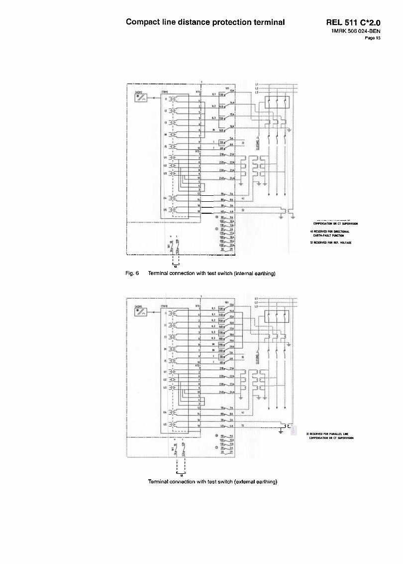
31 RfSERVED FDR PARALLEl UNECDHPENSATIDN DR CT SUPERVISlDN
41 RESERVED FDR DRECTlDNALEARTH-FAIx.T FUNCTIDN
51 RESERVED FDR REF. VOLTAGE
Fig.5 Terminal connection without test switch
1 MAK 506 024-BENPage 14
Compact line distance protection terminal REL 511 C*2.01MRK 506 024-BEN
Page 15
.., ,JA1., [jE"
",z j , f---u j f---~;]
:=3::tJ--.-' -
~--
L 15A~ :1!
~I
t;
l
.~
ji
.-"-11 , ~ 3 q-i'--' 3y
---:1- 1-~ ~
I
l
fj
---i~-~C_-j
~
+ I
I
~lt ,I II I
L..:;...Fig. 6 Terminal connection with test switch (internai earthing)
f u j ,---,-t-, , ':11~
'--I:j:::JJ],--_o, :=:::r::l_~_-
.I ' if.--", '-I. ~' [:__[[_1-::
..~,---;
~r---'1.-'- ,I , I'1__":3 :J q--r I "
:3 ?q-_C !-~.,i.-0000
2B~
I 22B ]l!
I 23B.--llit:::: 2'.~
==E'".--l!.18~
I 3B.--l!.
! ..~
.~i~A!~!
<D~!1!-.-1!!
i! ~~ j
~! ~~ ~ T
i
---1-I II II I
L-:-II.
Terminal connection with test switch (external earthing)
1123!~
I
o3:C=II
-3:C-II SA
1153:~- ,~t ~ I ,.,..-I
Ut 3111 'e~ I - U2 3: --' '28~ I r-'
I -PUJ 3' -'E Ni :I 9...' hI .,I:
."' äA1..-rI "*"
I o
I..3:C= J9~I I ~
U5 3:C= E~~.L ..~~
J
Iq3:~
I
o3:CI1
"3:~II153i~
U131iUJ 3: 1
U3 3'111
I :I 11
U43:C1
U53i~L

Compact line distance protection terminal R
Technical dataTable 1: Energising quantities, rated values and limits
I Quantlty
i Current
Rated value
Ir = 1 or 5 AIr = 1 or 5 A for 15
(0.004-100) x Jr4 x 'rcont.100 x Ir for 1 s I
< 0.25 VA at Ir
Ur = 100/110/115/120 VUr = 200/220/230/240 V
Nominal ral
Operation rangePermissive overfoad
Burden
Ac voltage Ph-Ph
Operation rangePermissive over1oad
Burden
Frequency
(0.001-1.5) x Ur1.5 x Urcont.2.5 x Ur for 1 s< 0.2 VA at Ur
fr = 50/60 Hz
EL = (48-250) V
:t5%
:t20%Auxiliary dc voltage EL
powerconsumptionbasic terminaleach output relay
power dissipatiol1RL24 = (24/30)VRL48 = (48/60)VRL110 = (110/125)VRL220 = (220/250)V
~16W~O.15W
I max. 0.05 W/input
max. 0.1 W/inputmax. 0.2 W/input, max. 0.4 W/input
Binary inpuVoutput moduledc voltage AL RL24 = (24/30) V
RL48 = (48/60) VRL110 = (110/125) V
i RL220 = (220/250) V
:t 20 %:t 20 %:t 20 %I
:t 20 %
power consumptioneach I/O-moduleeach output relay
power dissipationRL24 = (24/30)VRL48 = (48/60)VRL 110 = (110/125)V
RL220 = (220/250)V
$1.0W$ 0.15 W
!
max. 0.05 W/inputmax. 0.1 W/inputmax. 0.2 W/inputmax. 0.4 W/input
Binary input moduledc voltage RL
I
RL24 = (24/30) VRL48 = (48/60) VRL110 = (110/125) VRL220 = (220/250) V
1:1:20%:1:20%1
:1:20%1:1:20%
power consumptioneach input module
power dissipationRL24 = (24/30)VRL48 = (48/60)V
RL110 = (110/125)VRL220 = (220/250)V
I ~O.5W
,
max. 0.05 W/input
max. 0.1 W/inputImax. 0.2 W/inputmax. 0.4 W/input
Binary output moduls
power consumptioneach output modulseach output relay
*) max. 350 A for 1 s when COMBIFLEX tl12t = 10 kAs
~1.0W~ 0.25 W
IMAK 506 024-BENPage 16

Compact line distance protection terminal REL 511 C*2.01 MAK 506 024-BEN
Page 17
Table 2: Inflllencing factors, Permissible influence
I Dependence on:
I
Within operative rangeWlthln nominal range
0.01 %/oC
Negligible
I
Ambient temperature Correct function
Ripple in auxilii~ry dc voltage Correct function
Interruption in auxiliary dc voltageI with out resetting
correct fum=tionrestart time
I
< 50 ms
0-00< 100 s
<50ms0-00
< 100 s
Table 3: Electromagnetic compatibility tests
Test i Type test values Reference standards
2.5 kV2.5 kV
!
IEC 602!
IEC 6021
5-22-1, Glass III;5-22-1, Glass III
1 MHz burst disturbanceFor short-range galvanic modemFor galvani(~ interface*)
-common mode-differential mode
1 kVO.5kV
8kV8kV
4kV4kV1 kV
Glass III Glass II
I IEC 60255-22-2. Glass 11-'
lEG 60255-22-2, Glass III
I
Electrostatic dischargeFor short-range galvanic modemFor galvanic: interface ")
lEG 60255-22-4, Glass IVlEG 60255-22-4, Glass IVGlass II, level 2
Fast transient disturbanceI For short-range galvanic modem
For galvanic interface'
Radiated electro-magnetic fielddisturbance
10 V/m, (25-1000) MHz lEG 60255-22-3, Glass III! IEEE/ANSI C37.90.2
*) For FOX6Plus the following modes are not applicable:-V.36N11 Co-directional according to CCITT-RS530/RS.~22 Co-directional according to EIA
Table 4: Insul~ltion tests (reference standard: lEG 60255-5)1
I T;st I Type test values
Dielectric testFor short-range galvanic modemFor galvanic interface .,
Impulse voltage testFor short-range galvanic modemFor galvanic interface I
For other circuits
5 kV, 1.2/50 ILs, 0.5 J1 kV, 1.2/50 ILs, 0.5 JI 5 kV, 1.2/50 ILs, 0.5 J
Il;;sulation
re~stal'1ce
!
>100 Mil at 500 V dc
Table 5: CE-m~lrk
I Test I Type test values
Immunity -EmissivityI
Low volta ge directive
EN 50082-2
EN 50081-2
EN 50178
Table 6: Mechanical tests
I Type test values
Class I
Class I
Class I
i Reference standards
lEG 60255-21-1I
lEG 60255-21-2IIEC
60255-21-3
Test
VibrationI
I Shock and bumpI Seismic
1 2:0 kV ac, 1 min2.5 kVac, 1 min1.0 kV ac, 1 min

Compact line distance protection terminal C*2.0
Page 18
Technical data (cont'd)Table 7: Contacl: data (reference standard: IEC 60255)
I Function or quantity I !ast s~elays~ax system volt~ge
Trlp and Signal relays
250 V ac, dc
1000 V rms
1250 V ac, dc .I
ISOOVdcI Test v~ltage across open contact.1-;;;in
Current carrying capacitycontinuous1 s
1
8A10 A
1 8A
10 A
Making capacity at inductive loadwith UR>10 ms
0.2 s1.0 s
~
OA 10A
250 V/8.0 A
I
Breaki-;g Capacityf~~c, cos <p>0:4
0.4 A0.4A
250 V/8.0 A
48 V/1 A110 V/0.4 A220 V/0.2 A
I Breaking capacity for dc with UR<40ms 48 V/1 A110 V/0.4 A220 V/0.2 A250 V/0.15 A
I Maximum capacitive road -1onF
Table 8: Additional General Data
Weight approx. 1/2 of 19" rack: S 8.5 kg
Storage temperature -40 oG to +70 °C
Table 9: Front communlcatlonFunction : Value
Connectors i special electricloptic cable
Table 10: Serial communication (SPA)
Function Value
I Connectors and optical fibres glass or plastic
Table 11: Serial communication (LON)
Functlon Value
Compact line distance protection terminal REL 511 C*2.01 MAK 506 024-BEN
Page 19
Table 12: Serial communication (IEC 870-5-103)
I
Functlon
Protocol
Communication speed
Value
lEG 870-5-103I
I
9-600, 19200 biVs
!
Connectors ami optical fibres glass or plastic
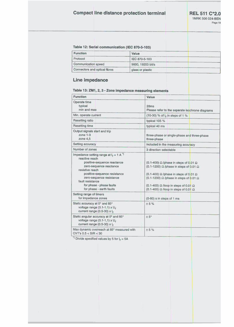
Line impedance
Table 13: ZM~I, 2, 3 -Zone impedance measuring elements
I Function
I
Value I -
28ms I
Please refer toithe separate isochrone diagrams
I (10-30) % of Ir in steps of 1 %
typical105 %
typical 40 ms
I
Operate timeI
typical
min and max
Min. operate currentI
Resetting ratio
Resetting time
Output signals start and tripzons 1-3zons 4,5
Setting accuracy
three-phase or single-phase and three-phasethree-phase
included in the measuring accuracy
I Number of zones
Impedance setting range at Ir = 1 A *)
reactive reachpositive-.sequence reactancezero-sequence reactance
resistive reach
positive-sequence resistancezero-sequence resistance
fault resistancefor phaSEt -phase faultsfor phasEi -earth faults
I 3 direction seleCtable
I
I
(0.1-400) .Q Iph.se in steps of 0.01 .Q
I (0.1-1200) .Q Iphase in steps of 0.01 .QI
(0.1-400) .Q Iphase in steps of 0.01 .Q(0.1-1200) .Q Ipryase in steps of 0.01 .Q
(0.1-400) .Q /loop in steps of 0.01 .QI (0.1-400) .Q /1001> in steps of 0.01 .Q
Setting range of timersfor impedance zones
I
(0-60) s in steps I of 1 ms
Static accuracy at 00 and 850Ivoitage
range (0.1-1.1) x Urcurrent range (0.5-30) x Ir
:1:5%
Static angular accuracy at 00 and 850voltage range (0.1-1,1) x Urcurrent range (0.5-30) x Ir
:t 50
Max dynamic overreach at 850 measured withCVT's 0.5 < SIR <: 30
:1:5%
") Divide specified values by S for Ir = SA

Compact line distance protection terminal 511 C*2.0
Page 20
Technical data (cont'd)Table 14: GFC -General fault criteria
Function Value
I General fault criteria (GFC) -impedance settingrange at Ir = 1A ')
reactive reach forwardpositive-sequence reactancezero-sequence reactance
reactive reach reversepositive-sequence reactancezero-sequence reactance
resistive reach (forward & reverse)for phase -phase faultsIfor phase -earth faultsroad encroachmentsafety load impedance angla
General fault criteria (GFC) -overcurrent setting
rangephase currentsresidual current
I (10-400) % of Ir in steps of 1 %(10-150) % of Ir in steps of 1 %
Timers for the GFC criteriafor phase measuringfor earth fault measuring
I (O-50) s in steps ofl1 ms(O-50) s in steps of 11 ms
*) Divide specified values by 5 for Ir = SA
Table 15: PSD -Power swing detection
Accuracy
I
Function Setting range
(0-60) s in steps of 1 msi (0-60) s in steps of 1 ms
(0-60) s in steps of 1 ms
(0-60) s in steps of 1 ms
Impedance setting range at Ir =1A ,reactive reach, XIN I (0.1-400) .QJphase in steps of q.01 .Q.
I resistive reach, AlN (0.1-400) .QJphase in steps of q.01 .Q.I reach multiplication facto r (120-200) % of XIN in steps of ~ %reach multiplication facto r (120-200) % of AlN in steps of %
Initial PSD timer (0-60) s in steps of 1 msi Fast PSD timer (0-60) s in steps of 1 msI Hold timer for activation of fast PSD
timerHold timer for PSD detected-nmer overcoming 1 ph reclosing deadI, time: -nmer to time delay block by the residual
currentOn delay timer for blocking of output! signal at very slow sw'ings
;
(0-60) s in steps of 1 ms
Static accuracy at 00 and 850 voltage range (0.1-1.1) x Urcurrent range (0.5-30) x Ir
:t5%
IStatic
angular accuracy at 00 and 850
I
voltagerange(0.1-1.1)xUr
current range (0.2-30) x Ir1:1:50
-) Divide specified values by 5 for Ir = 5A

Compact line distance protection terminal REL 511 C*2.0
Table 16: ZCOM, ZC1 P -
I Function
I (O-50) s in steps of 1 ms(O-50) s in steps of 1 ms
I
Unblocking logic
security timer (0-60) s in steps of 1 ms
Table 17: ZCJ\L -Communication additionallogic
Function Setting rangeWeak end infee,d tri p and echo function
Operate voltage U<
phase -phase
phase -earthCoordination time
(20-170) % Ur in steps of 11/0
(10-100) % Ur in steps of 1r/o(0-60) s in steps of 1 ms !
l Current reversalloglc
activation time delaytime delay of CR, CS
I (O-GO) s in steps of 1 ms(O-GO) s in steps of 1 ms
Table 18: SOT F -Automatic switch onto fault logic
I Function i Settin!
200m!
~ range
Function Setting rangeI
Automatic check of dead line condition
operate phase voltageoperate phase current
I (10-100) % of Ur in steps ot 1%(5-100) % of 'r in steps of 1f/o
Table 20: ZCLC: -Local acceleration logic
i Function I Setting range
lOn/Off
Operation loss of load lOn/Off
Current
Table 21: IOC -Instantaneous overcurrent protection
Setting range i Operate time I Accuracy
]' (50-2000)% of 'r
in steps of 1%
Operate current I»
phase measuring elements
(50-2000)% of Irin steps of 1%
residual measuring elements
Minimum operate time at I> 10 x 'set
I
max 15m$
I Dynamic overreach at'[ < 100 ms I1<5%
1 MAK 506 024-BEN
Page 21

Compact line distance protection terminal REL 511IMRK506
Technical data (cont'd)Table 22: TOC -Time delayed overcurrent protection
I
FunctionSetting range Accuracy
Operate current I>phase measuring elements
I
(10-400) % of Jr in steps of 1 %
residual measulring elements (10-150) % of Ir in steps of 1 %
Time delayphase measuring elementsresidual measuring elements
I (0-60) s in steps of 1 ms(0-60) s in steps of 1 ms
I
Dynamic overreach at 't < 1 00 m~ 1<5%
Table 23: BFP -Breaker failure protection
Function Settlng range
(5-200) % of Ir in steps of 1 %Operate current(one measuring element per phase)
I
Relrip lime delay 11 I (0-60) s in steps of 1 ms
I
Back-up trip ti~e delay t2 I (0-60) s in steps of 1 ms
I
Value
max 18 ms
max 10 ms
I Trip operate time
I
Operate time for current detection
Table 24: TEF -Time delay earth-fault
Function AccuracyI Setting range
Basic current, inverse time delay: 310 I (5-300) % of Ir in steps of 1 %
I
Selection of E/F protection Non-directional
I Operate valuefor directional
current measurementforward 310 at q> = 650
reverse
I
(5-35) % of Ir in steps of 1 %60 % of the setting for forward
operation
I
Independent ti~e delay I (0-60) s in steps of 1 ms
i:!:
0.5 %:!: 10 ms
Normal inverse characteristic k = (0.05-1.1) in steps of 0.01 lEG 255-3 class 5 :t 60 ms
Very inverse characteristic
I
k = (0.05-1.1) in steps of 0.01 lEO 255-3 Glass 7.5:t 60 ms
I Extremely invers e ch,aracteristic k = (0.05-1.1) in steps of 0.01
I
lEG 255-3 clas s 7.5 :t 60 ms
Logarithmic charactelristic
It = 5,8-1,35xln~o
:t 5 % of t atI = (1.3-29) x 310
Min. operate current for dependentcharacteristic IMin (100-400) % of 310 in steps of 1 %
I (O~O) s in steps-of 1 mstMin for dependent charact.-Rated voltage
i Minimum polarising voltageI Operate time
Resetting time
Ur1 % of Ur
Valu.< 70 ms
C*2.0024-BEN
Page 22

Compact line distance protection terminal REL 511 C*2.0
Table 25: EFC -Earth-fault communication
I
Function
!
Setting range
Communicatiol1 scheme None, Permissive, BlockingCoordinalion lilmer I (O-GO) s in steps of 1 ms
!
, Table 26: EFCA -Earth-fault communication additionall<tgic
I Function I Settlng range-- I
I Operate voltagl~ for WEllripCurrent reversal pickup timerCurrenl reversal delay limer
I (5-70) % of Ur in steps of 1 PI:(0-60) s in steps of 1 ms
l(0-60) s in steps of 1 ms
Power sy~;tem supervision
Table 27: BR(~ -Broken conductor check
Function
Operate currenti lime delay
Setting rangeI (10-100) % of 'r in steps of 11%
(O-SO) s in steps of 1 ms
Table 28: LOV' -Loss of voltage check
I Function I Setting range
I (10-100)';;: of Ur in steps of 1%
Table 29: OVLD -Overload supervision
I
Functlon
Operate current I>Time delay
I Setting range
I (20-300) % of Ir in steps of 1 flo(O-GO) s in steps of 1 ms I
Secondary system supervision
Table 30: FUSI: -Fuse failure supervision function
I
FunctlonSetting range
Zero-sequence quantities:operate voltage 3Uooperate current 310
I (10 -50)% of Ur in steps of 1°}..(10 -50)% of Ir in steps of 1%1
I
1 MAK 506 024-BEN
Page 23

Technical data (cont'd

Compact line distance protection terminall REL 511 C*2.01 MAK 506 024-BEN
Page 25
Table 35: Ba:sic logic
I Timers
i FunctionSetting rangeNumber
101-:;0-
110
10
I Timer I (O-ro) s in steps of 1 ms
I (0-90000) s in steps of 0.1 s
I
Long timer
Pulse timer -Pulse long timer-
I Loglc
Functlon
AND
I (O-GO) s in steps of 1 ms
I (0-90000) s in stepsl of 0.1 s
Number
30
160i 39
20
5
I Description
I 4 inputs {1 inverted)J2 outputs {inver
led
and non-inverted) I
!OR I 6 inputs, 2 outputs (inverted and non-inverted)
2 inputs, 2 outputs (inverted and non-inverted)
2 inputs, 2 outputs (inverted and non-inverted)
Table 36: Additionallogic
Timers
FunctlonI Pulse timer
Loglc
I
Number
40
I Setting range
I (O-50) S in steps of 11ms
I Function
I
Number
239
159
59
I Description
lAND
OR
4 inputs (1 inver1ed),2 outputs (inver1, Id and non-inverted) I
I
6 inputs, 2 outputs (inverted and non-inverted)
IINV
Monitoringi
Table 37: DREI~ -Disturbance recorder
Setting rang. I
0-48
0-102kHz
(5-250) Hz
(O -5000) % of I in steps of 1 %
Functlon
Number of binary' signals
Number of analogue signals
Sampling rate!
Recording bandwidth
Overcurrent triggl~ring
I Undercurrent triggering I (O -200) % of Ir in steps of 1 %
I (O -200) % of U~ in steps of 1 %! Overvoltage triggl3ring at 100 V sec
I Undervoltage trig!Jering I (O -110) % of Ur!in steps of 1 %
Pre-fault time
Post fault time
I (10 -300) ms in steps of 10 ms
I (100 -3000) ms in steps of 100 r
I Limit time I (500 -4000) ms in steps of 100 ms
Number of recorded disturbances
Total recording time with 10 analogue and48 binary signals *) recorded
Max 1 O di~turba~ces
maximum 40 s
I VoItage channels
dynamic rangeresolution
(0.01-2.0) x Ur at \100 V seco! 0.1 %ofUr

Compact line distance protection terminal REL 511IMAK 506
Technical data (cont'd) Table 37: DREP -Disturbance recorder
I Setting range
I (0.01-110) x Ir(0.01-60) x Ir0.5 % of If
I
Functlon
Current channelsIdynamic range
with out dc offsetI with full dc offset
resolution
, Built-in calendar I for 30 years with leap years
*) The amount of harmonics can affect the maximum storage time
Table 38: Event recorder
Function Value
1 ms
15010
1:t1o5mS, :t 1.5 ms
Time tagging resolutionEvent buffering capacity
Max. number of events/disturbance repan! Max. number of disturbance repans
Time tagging error vvith synchronisation once/1 sTime tagging error with synchronisation once/10sTime tagging error Y/ith synchronisation once/60sI
(minute pulse s}'nchronisation)Time tagging error \\/ithout synchronisation
:!: 1.5 ms:!: 3 ms/min
Table 39: FLC -Fiault locator
Function Setting rangeDislance lo faull localor
reach for Ir =1 A inresislive direclionreaclive dire,~lion
phase seleclion
I (O -1500) Q/phase
(O -1500) Q/phase
internai
Table 40: Mean vallues
Function~~~~!
Voltage
Settlng range
(0.95-1.05) xfr
(0.1-1.5) x Ur
~
~=ccuracY :t 0.2 Hz
:t 2.5 % of Ur:t 2.5 % of U I
:t 2.5 % of Ir at I S Ir:t 2.5 % of I at I > 'r
:t5%:t 7.5 %
at U S Urit U > Ur
Current (0.2-4) x Ir
I ~:~~:.~~~~.~.~- OjReactive power *)at lcos C/l1 ~ 0.9at Icos C/l1 ~ 0.8
I Measured at Urand 20 % of Ir
C*2.0024-BEN
Page 26

Compact line distance protection termina~ REL 511 C*2.0
Ordering The REL 511 C is a phase-to-phase and phase-to-earth line
~ stance prote( three impedalrlce measuring zones and separate general faut criteria. Seve:
functions are also included.
:tion terminal withral other protective
Ordering Number: 1 MAK 002 488-AA Qu .
Includes basic functions and the selected functions and hardware optio s below
Basic data:
Frequency, fr 50/60 Hz
Dc voltage, EL 48/60/110/125/220/250 V
Basic data to spec:ify:
Ac inputs
1 A, 110V
5A,110V
1A,220V
5 A, 220 V
Interface dc voltage
24/30 V
48/60 V
110/125 V
220/250 V
o 1MRto 1 MR~
D 1MR~
01MR~
< 000 157-MA
(000 157-NA
C 000 157-VA
C 000 157-WA
D1MRI<
D1MRK
D1MRK
D 1MRK
:
000 179-EA:
000 179-AB:
000 179-BB
000 179-CB
Factory configuration
Standard configuration, single- or multi-pole tripping
81MRK
8 1 MAK
81MAK
81MAK
81MAK
8 1 MAK
81MAK'
001 456-AA
001 456-CA
001 456-DA001
456-LA001
456-NA001
455-PA001
456-RA
B1MRK(
81MRK(
81MRK(
)01
457-AA)01
457-BA
}01 458-AA
Functions;
.= function always included
Line impedance
General fault criteria protection, impedance and/or current-based
3 zones phase-phasEl protection
3 zones phase-earth protection
Power swing detection
Scheme communication logic
Current reversal and weak end infeed logic
Automatic switch anta fault logic
Current, phase wise
Instantaneous phase overcurrent protection
Time-delayed phase overcurrent protection
Breaker failure protection
Current, residual (ealrth fault)
Instantaneous residual overcurrent protection (non-directional)
Time-delayed residua I overcurrent protection (non-directional)B1MRKC
B1MRKC
)01 456-VA
)01 456-XA
1MRK 506 024-BEN
Page 27

C*2.0Compact line distance protection terminal
Page 28
Ordering (cont'd)Note: Only one of the following two alternatives below can be selected.
Inverse time residual overcurrent protection (non-directional)
Residual directional check, inverse time residual overcurrent protection andcommunication logic (directional element)
Power system supervision
Broken conductor check
Loss of voltage check
Overload supervision
Secondary system supervision
Fuse failure supervision (Zero sequence)
Controi
Synchro-check and energising-check, single CB
Autorecloser logic, 1 and/or 3 phase, single CB
Logic
Single or two pole tripping logic
Pol e discordance logic (contact based)
Additional configurable logic
Monitoring
Disturbance recorder, 40 s
Event recorder
Fault locator
Trip value recorder
Hardware options;
Casing
1/2x 19" (max. 31/0)1MRKOOO 151-FA
I
Case size
Combined binary input/olJtput andoutput modules (max) 3

Compact line distance protection terminal REL 511 C*2.01 MAK 506 024-BEN
Page 29
I/O modules
3 modules are available in the 1/2 x 19" case.
Quantity lOrdering number
Binary input modul e
(16 inputs)
InterfaceDC voltage
24/30 V
48/60V
110/125 V
220/250 V
24/30 V
48/60V
110/125 V
220/250 V
I 1 MAK 000 508-DA
I 1 MAK 000 50B-AA
11MRK 000 508-BAI I -11 MA~ 000 508-CA -
I 11 MAK 000 173-GABinary inpuVoutput module(8 inputs and 12 outputs)
11 MAK 000 173-AB
i 1 MAK 000 173-88
11 MAK 000 173-CB
! 1MRK 000 614-AABinary output modulei (24 single outputs or 12 command outputs)
Note: One binary inlDut!output module is included for standard factory cohfiguration.
Serial communication modules
Serial communication for SMS and SCS; (one alternative per po )
SMS, port SPAlIEC 870-5-103 (Iocation X13)
PlastiC/Plastic
Glass/Glass
SCS, pon LON (Iocation X15)
Plastic/Plastic
Glass/Glass
Engineering facilities
HMllanguageSecond language besides English
German
Russian
French
Spanish
ltalian
D 1 MAK 001 459-BA
D 1MAK 001 459-CA
D 1 MAK 001 459-DA
Customer-specific ordering
Customer-specific order number
Combiflex
COMBITEST test switch module RTXP 24 mounted withthe terminal in RHGS6 case with window door
DIntemai earthing RK 926 215-BB D External earthing RK 9~6 215-BC
On/Off switch for the dc supply ORK 795 017-AA I

RiEL 5111MRK506
Ordering (cont'd)
D1MRKO
D1MRKOI
D1MRKOI
D 1MKC 91
D 1MRK DI
D 1MKC 9!
00
020-BR00
020-DA
)0020- Y
30001-2
)0 020-BS
~O 001-2
Mounting details with IP40 degree of protection from the front:
19" rack
Wall mounting
Flush mounting
addition al for IP54 (protection terminal only)
Semi-flush mounting
additional for IP54 (protection terminal only)
Quantity: ~ 1MRK 606 003-UEN
Quantlty: ~ 1MAK 00Quantity: ~ 1 MAK 00
o
611-Ao
486-AA
Quantlty: 1 MKC 95
Quantity: 1 MAK 00
Quantity: 1MAK 001
Quantlty: 1MAS 15
1MAKOO.
0001-1
O 876-KB
O 876-PA1400
1700-4
Quantity: AS 881 OC
Quantlty: 1 MAK OOC
Quantity: AS 881 01
QUantity: 1MAK 000
Quantlty: 1MAK 000
)7-AA
I 314-MA
1-AA
IO77-DC
'O7S-AB
Accessories:
User documentation
Technical reference manual, REL 511
Combiflex
Key switch (for locked ~;ettings)
Resistor unit for creation of 3Uo voltage (RXTMA 1)
Configuration and molnitorlng tools
Front connection cable Ilor PC (Opto/9-pol D-sub)
CAP 531, Graphical corlfiguration tool (IEC 1131-3)
CAP/REx 500, CAP software module
LNT 505, LON configuration toor
SLDT, LON configuration module REx 500available on our website: www.abb.se/net
SMS-BASE, Basic program for all SMS applications
SM/REx 500, SMS soft\'o'are module
REPORT, program for e',ent and alarm handling in SMS
RECOM Disturbance collection program
REVAL Disturbance evaluation program, English version
MicroSCADA tools
LIB 520, MicroSCADA engineering toolQuantity: cp On request
>n data:
Country: End user:
Station name:Voltage level: kV
C*2.0024-BEN
Page 30
REL 511 C*2.0
References Series RE 5~)Mechanical design and mounting accessories lMRK 514 003-BEN
Technical refi:rence manual, REL 511 lMRK 606 003-UEN
Reference list. REL 511 lMRK 50~ 002-REN
Lm 520lMRK 5111o57-BEN
SMS 010 lMRK 5111014-BEN
CAP 531lMRK5111056-BEN
Man ufacturer ABB Automa1:ion Products AB5ubstation Automation Division5-721 59 Västerås
5wedenTel: +4621 3420100Fax: +46 21146~918
1 MAK 506 024-BEN
Page 31

Compact line distance protection terminal
Page 32