rekluse motor sports - deutschland · pdf filerekluse motor sports the z-start pro clutch ......
TRANSCRIPT

REKLUSE MOTOR SPORTS
The z-Start Pro Clutch
INSTALLATION GUIDE
Clutch Cable Actuated Models
191-800
Manual Revision: 041513
©2012 Rekluse Motor Sports Rekluse Motor Sports, Inc. 12000 W Franklin Rd. Boise, Idaho 83709 208-426-0659

z-Start Pro Installation Guide 2
TABLE OF CONTENTS
z-START PRO CROSS-SECTION VIEW 3
INCLUDED PARTS 3
REQUIRED TOOLS 3
BIKE PREPARATION AND DISASSEMBLY 4
CLUTCH BASKET INSPECTION 5
INSTALLING THE z-START PRO CENTER CLUTCH 6
INSTALLING THE CLUTCH PACK 7
INSTALLING THE Z-START PRO CLUTCH 8
DETERMINE THE INSTALLED GAP OF THE Z-START PRO CLUTCH 11
SETTING CLUTCH CABLE SLACK 13
APPENDIX A – CENTER CLUTCH REMOVAL TIP SHEET 14

z-Start Pro Installation Guide 3
Z-START PRO CROSS-SECTION VIEW
INCLUDED PARTS
Item Item
� Top Plate
� Pressure Plate
� Rekluse Center Clutch
� Retaining Ring
� (8) RMS Measured Drive Plates
� (1) RMS .065” OR .060” Drive
Plate (Adjustment Plate)
� Rotating Hub Assembly
� External Tab Lock Washer
� Lever Return Spring Carrier
� Rekluse Throw-out Spacer
� Rekluse Oil Spigot (CRF250R
Only)
� (27) 7/16” Chrome Steel Ball Bearings
(big bore bikes)
� (30) 3/8” Chrome Steel Ball Bearings
(small bore bikes)
� (10) M4x12 Torx Head Screws
� Wave Springs – See Included Tuning
Chart for your Model
� T-20 Torx Bit
� Blue Loctite 243
� Rekluse Clutch Cover Gasket
� Rekluse Wire Gauges
REQUIRED TOOLS
• 8mm socket
• 10mm socket
• 27mm or 30mm socket
(for center clutch nut)
• T-20 Torx bit (supplied)
• Impact Wrench
Top
Plate
Friction
Disk
Drive
Plate
Retaining
Ring
Rotating Hub
Assembly Stock Throw-out,
bearing, and washer
Pressure
Plate
Center
Clutch
Lock
Washer
Lever Return
Spring Carrier
Throw-out
Spacer

z-Start Pro Installation Guide 4
BIKE PREPARATION AND DISASSEMBLY
1. Before you begin, read these instructions
carefully and check to ensure all parts
are present.
2. Disconnect the clutch cable at the clutch
perch.
3. Shut off fuel at petcock. Lay bike on left
side. CAUTION: fuel may drain from
carburetor; to prevent fire hazard, place
a suitable container beneath bike to
catch fuel.
4. Remove clutch cover.
5. Remove bolts and springs from OEM
pressure plate.
6. Remove OEM pressure plate.
NOTE: Flat throwout thrust washer
(coupled with needle bearing and OEM
throwout) may be stuck to bottom of
OEM pressure plate. Retain as it will be
re-used.
7. Remove OEM clutch throw out and set
aside. It will be re-installed.
8. Remove the clutch pack (friction disks
and drive plates). Separate the friction
disks from the pack as they will be re-
installed.
9. 2008 CRF250 ONLY: remove clutch
boss spring located at base of OEM
center clutch. It will not be re-installed.
10. Remove the OEM center clutch hub
following the steps outlined in the
vehicle manufacturer’s service manual.
Also, see the center clutch removal tip
sheet (Appendix A) for further
assistance.
11. Retain OEM thrust washer located
between OEM clutch basket and OEM
center clutch hub.
NOTE: thrust washer may be stuck to
bottom of OEM center clutch hub.
12. Aprilia 450/550 and Suzuki RM250 2-
stroke owners ONLY: Remove stock
clutch basket and install Rekluse Clutch
Basket prior to step 13. Refer to
included Rekluse Clutch Basket
Installation Guide for instructions.
z-Start Pro Installation Guide 5
CLUTCH BASKET INSPECTION
NOTE: The following outlines Clutch Basket
Damper Failure. Some Clutch baskets will
last a season, and some last only hours. If
the dampers go unchecked, clutch damage
will result. After inspecting the basket,
continue with the z-Start Pro installation.
Clutch Basket Damper Operation
Most OEM Clutches use elastomer dampers
to protect the clutch from shock loading
applied to the basket by the drive train
and/or engine during normal operating
conditions. The dampers are located
between the clutch basket body and the
ring gear. These dampers take up the slack
between the ring gear and clutch basket so
that under normal loading they rotate as
one. Under extreme loading the dampers
provide a cushion so the ring gear and
basket can float independently and keep
shock loads from being transferred to the
clutch.
As the dampers wear, the system gains
slack and shock loads start getting
transferred to the clutch. This creates a
hammering effect between the clutch
basket and ring gear. The hammering
transfers to the clutch plates and causes the
plates to wear away at the clutch basket
and center clutch hub. If the dampers
continue to go unchecked, the hammering
progresses until the clutch fails.
Checking Your Clutch Basket for Damper Failure
Prior to installing the z-Start Pro, it is
recommended that you check the condition
of your Clutch Basket and Center Clutch
Hub.
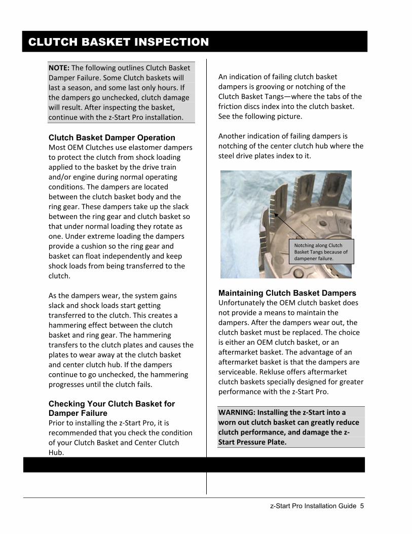
An indication of failing clutch basket
dampers is grooving or notching of the
Clutch Basket Tangs—where the tabs of the
friction discs index into the clutch basket.
See the following picture.
Another indication of failing dampers is
notching of the center clutch hub where the
steel drive plates index to it.
Maintaining Clutch Basket Dampers Unfortunately the OEM clutch basket does
not provide a means to maintain the
dampers. After the dampers wear out, the
clutch basket must be replaced. The choice
is either an OEM clutch basket, or an
aftermarket basket. The advantage of an
aftermarket basket is that the dampers are
serviceable. Rekluse offers aftermarket
clutch baskets specially designed for greater
performance with the z-Start Pro.
WARNING: Installing the z-Start into a
worn out clutch basket can greatly reduce
clutch performance, and damage the z-
Start Pressure Plate.
Notching along Clutch
Basket Tangs because of
dampener failure.

z-Start Pro Installation Guide 6
INSTALLING THE Z-START PRO CENTER CLUTCH
13. Install the Rekluse Center Clutch with the OEM thrust washer behind it on top of the
basket.
14. Install the included Rekluse external tab lock washer* over the main-shaft on top of the
Rekluse center clutch.
*NOTE: KX/KLX/KFX450F, KX250F, ‘04-‘06 RMZ 250, ’06-’08 RM250,
YZ/WR250F and 2012 WR450 use OEM lock washer.
NOTE: Some Honda models use a flat washer under the OEM lock washer.
For these models, re-use the OEM flat washer under the Rekluse lock
washer.
15. Torque the center clutch nut to the specified torque found in the manufacturer’s service
manual.
16. Using a pair of adjustable pliers, bend remaining two tabs of external tab washer up
against the nut to secure it. See photo below.

z-Start Pro Installation Guide 7
INSTALLING THE CLUTCH PACK
17. The 8 Rekluse steel drive plates packaged with the Rekluse Center Clutch come pre-
measured and are the 8 steel drive plates you will start with.
Install 1 Rekluse steel drive plate onto the Rekluse Center Clutch.
NOTE: A Rekluse steel drive plate must be the first clutch plate installed.
18. Install the stock friction disks with a Rekluse steel drive plate between each one. (Aprilia
owners – see tuning guide before proceeding). See following chart:
NOTE: Some bikes have 9 friction disks stock. With the z-Start Pro you use 8 Friction
disks.
WARNING: Do not install the OEM 2-piece clutch boss spring (located at the base of the
stock center clutch) if your bike had one.
Top of Pack
Stock Friction disk Last Plate In
Rekluse Steel Drive Plate
Stock Friction disk
Rekluse Steel Drive Plate
Stock Friction disk
Rekluse Steel Drive Plate
Stock Friction disk
Rekluse Steel Drive Plate
Stock Friction disk
Rekluse Steel Drive Plate
Stock Friction disk
Rekluse Steel Drive Plate
Stock Friction disk
Rekluse Steel Drive Plate
Stock Friction disk
Rekluse Steel Drive Plate First Plate In
Bottom of pack

z-Start Pro Installation Guide 8
INSTALLING THE Z-START PRO CLUTCH
19. Place lower assembly into Rekluse
center clutch hub. You must align
the three cut-outs in the lower
assembly with the corresponding
tabs in the center clutch. NOTE:
some models only have two cut-
outs.
20. Using a pair of mechanics gloves (the
edges of the ring can be sharp and
may cut you), install the retaining ring
into the Rekluse Center Clutch ring
groove.
You must ensure the retaining ring is
snapped into the groove. Start the
square end of the ring and thread the
ring into the groove as shown, ensuring
that the scalloped end of the ring is
clockwise in relation to the square end.
WARNING: Scalloped end of ring MUST
be oriented as shown above-right.
Threading retaining ring into groove
Use a screwdriver to ensure the ring is seated by sliding along the ring’s inner diameter.
WARNING: It is CRITICAL that the
retaining ring is fully seated using a
screwdriver, or clutch damage
WILL occur.
Rekluse lower
assembly
Cut-outs
Scalloped end of ring correctly oriented:
clockwise in relation to square end.

z-Start Pro Installation Guide 9
21. Install OEM clutch throw-out with bearing
and washer on top into the transmission
shaft. Ensure the needle bearing and flat
thrust washer is placed on top of throw-
out. Note: some models may have a
circlip that retains washer and bearing to
throwout.
NOTE: RMZ250 bearing has rollers on only
one side. Rollers MUST face down onto
throwout.
22. Install the Rekluse throw-out spacer on
top of the throw-out.
NOTE: YZ250 owners be sure to use
throwout spacer (etched with part #002A)
and NOT brake spacer (which has raised
surface) referred to in step 37.
23. Configure throwout according to
following diagrams:
24. Read the Setup and Tuning Guide to
determine desired spring setting.
25. Install the C150 wave spring on top of
clutch lever return spring carrier.
OEM Throw-out with
bearing and washer
Rekluse
Spacer
Rekluse Spring
Carrier
Rekluse Spring
Carrier
OEM Throw-out with
bearing and washer
Rekluse
Spacer
Rekluse Oil
Spigot
Flat Thrust Washer
Needle Bearing
OEM Throwout
All models EXCEPT 2004-2009 CRF250R/X:
2004-2009 CRF250R/X ONLY:

z-Start Pro Installation Guide 10
26. Install the C200 wave spring (if used by
chosen configuration) on top of rotating
hub into the locating pocket.
27. Place a small amount of oil into the ball
grooves of the Rekluse Pressure Plate.
28. Away from the bike, install the steel balls
into the pressure plate ball grooves. Refer
to Setup and Tuning Guide for desired
number of balls and proper distribution
pattern.
If your basket has 2 sets of slots, make
sure you index the Rekluse pressure plate
tabs into the main/deep slots.
29. Push and hold the pressure plate down,
overcoming the wave spring(s) so the 10
rotating hub posts index into the 10
pressure plate holes.
30. While holding down the pressure plate
so it is indexed with the basket and 10
rotating hub posts properly, place the
Rekluse top plate over the Rekluse
pressure plate and thread in 2 torx
head screws180° across from one
another. Lightly tighten the 2 screws
to secure the Rekluse top plate.
Rotating hub posts indexed
into pressure plate holes.

z-Start Pro Installation Guide 11
DETERMINE THE INSTALLED GAP OF THE Z-START PRO
CLUTCH
NOTE: Installed gap is measured using two no-
go wire gauges. Therefore, if gauges do not
slide between Rekluse pressure plate and the
pads of the top friction disk, your installed gap
is correct.
If gauges do slide between the Rekluse
pressure plate and the pads of the top friction
disk, you need to adjust your installed gap
according to step 33.
31. Verify that the top-most friction disk moves
up and down freely between the Pressure
Plate and top-most steel drive plate by pulling
up and down on top-most friction disk. If no
“float” exists, top-most steel drive plate has
become disoriented during previous step and
needs to be re-installed.
32. Attempt to slide the shorter legs of the 2
included .050” no-go wire gauges between
the Rekluse pressure plate and the friction
pads of the top friction disk 180° apart.
If clutch pack wear exists, gauges will slide in
with slight resistance. Do not force the gauges
in; if the gauges do not slide in smoothly then
the Installed Gap is good and you can move on
to step 34.
33. If the wire gauges slide in smoothly, the
clutch pack needs adjustment. Swap the
thick Rekluse adjustment drive plate for
the top drive plate. Repeat step 33.
NOTE: The adjustment drive plate is .060”
for small bore bikes and .065” for big
bore bikes. Once the drive plate has been
used and the clutch wears enough so the
wire gauges slide in again, the friction
disks need to be replaced. Use the small leg of
wire gauges.
Try to slide wire gauges
between pressure plate and
pads of top friction disk.
Attempt to slide both
gauges in 180° apart
simultaneously

z-Start Pro Installation Guide 12
34. Install the remaining 8 Torx head screws using
blue Loctite 243 and torque to 25 in-lb (2.08
ft-lb).
35. Remove the 2 screws originally installed
without Loctite, apply Loctite and torque.
36. Re-install the clutch cover with thicker Rekluse
Gasket—only the YZ/WR 250F, CR500, and
2010+ CRF250R do not require a thicker
gasket. Lightly tighten all of the cover bolts
before full torque is applied, or you may break
the cover. Note: Aprilia models refer to tuning
chart before installing clutch cover.
WARNING: If your kit came with two gaskets,
you MUST use both or clutch damage will
result.
(Exception 1: CRF 450R. If you have the
RMS-813 kit, two gaskets are included; one
gasket applies to 02-08 model years and the
other to 2013+ models.) If your bike is 09-11,
disregard this message and use the one
supplied gasket.
(Exception 2: CR 250R. This kit includes
two gaskets; one gasket applies to 97-01
model years and the other to 02-07 models.)
37. ’99-’04 YZ250 only: Install the brake pedal
spacer with the raised surface towards the
brake pedal as shown:
38. Reconnect the clutch cable to the lever and
stand the bike upright.
IMPORTANT: SEE NEXT PAGE OF
INSTRUCTIONS FOR PROPER CABLE
SLACK SETTING
Adjust the cable slack for the z-Start Pro
(SEE NEXT PAGE).

z-Start Pro Installation Guide 13
SETTING CLUTCH CABLE SLACK
IMPORTANT: Cable slack adjustment is critical. The cable slack must be adjusted properly and
maintained frequently. Failure to do so will result in clutch failure.
Adjusting cable slack is different with a z-Start Pro Clutch installed. Cable slack adjustment
requires starting the motor in neutral and revving to a minimum of 4500 RPMs (approximately
½-throttle) while checking for lever free play. There must be clutch lever free play while
holding a minimum of 4500 RPM.
If there is not enough cable slack, the clutch will slip excessively causing the clutch to fail.
Too much cable slack reduces the ability to disengage the clutch at higher RPMs.
WARNING: Ensure the bike is in neutral or it could lunge forward unexpectedly when revving
the engine.
Place the bike into neutral and start the
engine. While holding a minimum of 4500
RPM, check for 1/2" (1cm) of play at the end
of the clutch lever before you feel significant
resistance. Adjust cable slack accordingly
using stock cable slack adjuster(s).
In other words, when revving the engine,
clutch lever free play should feel like stock.
Tip: Use one finger with light pull when
checking for lever free play. This will
make it easier to distinguish between
the light resistance of the lever return
spring and the significant resistance felt
when disengaging the Rekluse pressure
plate.
Note: Be sure to review the included
Break-in and Maintenance Guide for
clutch pack wear adjustments.
WARNING: After a 20 minute break-in
period, the clutch plates will seat in
and you must re-measure the Installed
Gap to guarantee the Installed Gap is
within the prescribed range—make
drive plate adjustments if necessary.
Clutch break-in re-measurement of the
Installed Gap is necessary whenever
new clutch plates are installed.
Refer to the “Safety Warnings” and
“Break-in Tuning and Maintenance
Guide” before operating the z-Start Pro
clutch.

z-Start Pro Installation Guide 14
APPENDIX A – CENTER CLUTCH REMOVAL TIP SHEET
The following covers 3 methods for removing the OEM center clutch from your motorcycle or ATV. At
no time should you ever pry against the standoffs of the OEM center clutch because they are easily
broken.
Note: If your bike has an external tab lock washer, use a flat blade screwdriver to pry the tabs away from
the nut. Next use a hammer and punch to lightly tap the tabs flat.
1. Pneumatic or electric impact gun:
Place the bike in gear and remove the nut
2. Clutch Holding Tool:
Example: Motion Pro # 08-0008
Use the clutch holding tool to hold the center clutch while using a wrench to remove the center
clutch nut.
3. Holding the Rear Brake:
Place the bike in 4th
or 5th
gear (a higher gear gives you more mechanical advantage). Apply the
rear brake firmly and hold firmly while using a wrench to remove the center clutch nut. A
second set of hands is helpful.