reinforced earth company ltd hapas certificate high ... · bs en iso 898-1 : 2013, hot-dip...
TRANSCRIPT

Page 1 of 12
Reinforced Earth Company Ltd
Innovation House Euston Way, Town Centre Telford Shropshire TF3 4LT Tel: 01952 201901 Fax: 01952 201753 HAPAS Certificate e-mail: [email protected] 18/H276 website: www.reinforcedearth.co.uk Product Sheet 1
HIGH ADHERENCE STRIP AND PANEL LUG SYSTEM HIGH ADHERENCE STRIP AND PANEL LUG SYSTEM FOR REINFORCED SOIL RETAINING
WALL AND BRIDGE ABUTMENTS
This HAPAS Certificate Product Sheet(1) is issued by the British Board of Agrément (BBA), supported by Highways England (HE) (acting on behalf of the Overseeing Organisations of the Department for Transport; Transport Scotland; the Welsh Assembly Government and the Department for Infrastructure, Northern Ireland), the Association of Directors of Environment, Economy, Planning and Transport (ADEPT), the Local Government Technical Advisers Group and industry bodies. HAPAS Certificates are normally each subject to a review every three years. (1) Hereinafter referred to as ‘Certificate’.
This Certificate relates to the High Adherence Strip and Panel Lug System for reinforced soil retaining wall and bridge abutments, comprising high adherence reinforcing strips with panel lugs used in conjunction with precast reinforced concrete facing panels, to construct reinforced soil retaining walls and bridge abutments.
CERTIFICATION INCLUDES: • factors relating to compliance with HAPAS
requirements • factors relating to compliance with Regulations where
applicable • independently verified technical specification • assessment criteria and technical investigations • design considerations • installation guidance • regular surveillance of production • formal three-yearly review.
KEY FACTORS ASSESSED
Design — interaction between the high adherence strips and panel lugs and the soil/concrete facing panels has been considered (see section 6).
Mechanical properties — the system, when used in accordance with this Certificate, has satisfactory structural characteristics for use in reinforced soil retaining wall and bridge abutments (see section 7).
Durability — the system can achieve a design life of 120 years (see section 9).
The BBA has awarded this Certificate to the company named above for the system described herein. This system has been assessed by the BBA as being fit for its intended use provided it is installed, used and maintained as set out in this Certificate.
On behalf of the British Board of Agrément
Date of First issue: 16 March 2018
Paul Valentine Technical Excellence Director
Claire Curtis-Thomas Chief Executive
The BBA is a UKAS accredited certification body – Number 113. The schedule of the current scope of accreditation for product certification is available in pdf format via the UKAS link on the BBA website at www.bbacerts.co.uk Readers are advised to check the validity and latest issue number of this Agrément Certificate by either referring to the BBA website or contacting the BBA direct.
British Board of Agrément Bucknalls Lane Watford Herts WD25 9BA
©2018
tel: 01923 665300
[email protected] www.bbacerts.co.uk
Page 2 of 12
Requirements In the opinion of the BBA, the High Adherence Strip and Panel Lug System for use in reinforced soil retaining wall and bridge abutments, when used in conjunction with precast concrete facing panels and designed and installed in accordance with the provisions of this Certificate, will meet or contribute to meeting the requirements of Highways England and local Highway Authorities for the design and construction of reinforced retaining walls and bridge abutments.
Regulations
Construction (Design and Management) Regulations 2015 Construction (Design and Management) Regulations (Northern Ireland) 2016 Information in this Certificate may assist the client, designer (including Principal Designer) and contractor (including Principal Contractor) to address their obligations under these Regulations. See section: 3 Delivery and site handling (3.1) of this Certificate.
Additional Information
CE marking The Certificate holder has taken the responsibility of CE marking the system in accordance with harmonised European Standard BS EN 10025-1 : 2004.
Technical Specification
1 Description 1.1 The High Adherence Strip and Panel Lug System for reinforced soil retaining wall and bridge abutments comprises:
• high adherence strips
• panel lugs
• bolts and nuts — for attaching the high adherence strips to the panel lugs
• precast concrete facing panels
• frictional fill.
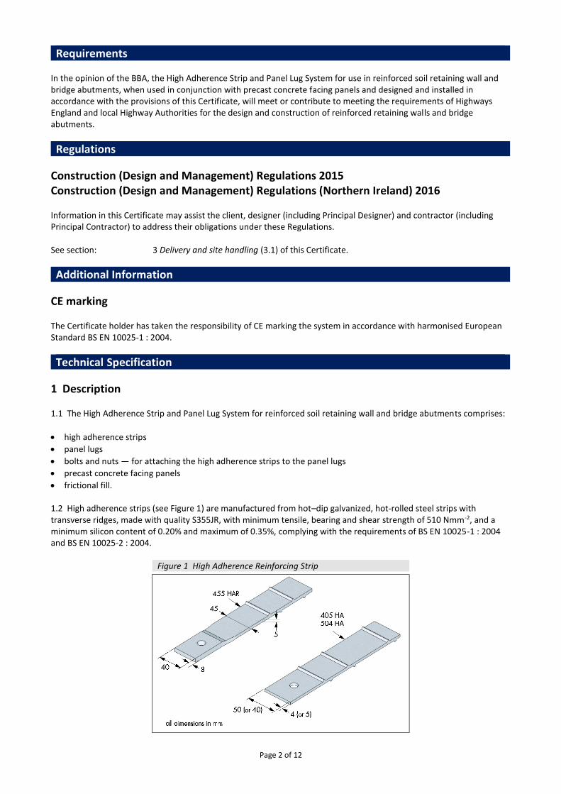
1.2 High adherence strips (see Figure 1) are manufactured from hot–dip galvanized, hot-rolled steel strips with transverse ridges, made with quality S355JR, with minimum tensile, bearing and shear strength of 510 Nmm-2, and a minimum silicon content of 0.20% and maximum of 0.35%, complying with the requirements of BS EN 10025-1 : 2004 and BS EN 10025-2 : 2004.
Figure 1 High Adherence Reinforcing Strip

Page 3 of 12
1.3 The panel lugs (see Figure 2) are manufactured from hot–dip galvanized, hot-rolled steel strips made of quality S355JR, with minimum tensile, bearing and shear strength of 510 Nmm-2, having a silicon content of not less than 0.2% and maximum of 0.35%, complying with the requirements of BS EN 10025 -1 : 2004 and BS EN 10025-2 : 2004.
Figure 2 Panel lug
1.4 After fabrication, the high adherence strips and panel lugs are hot-dip galvanized to BS EN ISO 1461 : 2009, with a minimum average zinc coating thickness of not less than 70 microns. 1.5 The 12 mm diameter bolts are steel alloy grade 10.9 to BS 3692 : 2014 or BS EN ISO 4014 : 2011 grade A, and BS EN ISO 898-1 : 2013, hot-dip galvanized to BS EN ISO 1461 : 2009.
1.6 The 12 mm diameter nuts are steel alloy grade 8 to BS 3692 : 2014 or BS EN ISO 4032 : 2012, style 1, grade A and BS EN ISO 898-2 : 2012, hot-dip galvanized to BS EN ISO 1461 : 2009.
1.7 Nominal dimensions and the design strength (TD) of the high adherence strips and panel lugs are given in Table 1.
Table 1 Properties of high adherence strips and panel lugs Type Nominal width
(mm) Nominal thickness
(mm) Design strength, TD
(1)(2) (kN)
Main body Connection
405HA 40 5 38.8 24.0 504HA 50 4 37.1 25.9 455HAR 45 5 43.9 42.2(3) Panel lug 45 4 — 42.2 (1) Assumes a design life of 120 years. (2) Includes a partial factor (fn) of 1.1 to allow for ramifications of failure. See BS 8006-1 : 2010, Table 9, and section 7 of this Certificate. (3) Connection capacity limited by panel lug.
Specification for precast concrete facing panels 1.8 The precast concrete facing panels, used in conjunction with the high adherence strips and panel lugs, must be designed and manufactured in accordance with BS 8006-1: 2010, BS EN 14475 : 2006, BS EN 1992-2 : 2005 and the requirements of this Certificate. Specification for frictional fill 1.9 The frictional fill must comply with the requirements set out in BS 8006-1 : 2010 and the Manual of Contract Documents for Highways Works (MCHW), Volume 1 Specification for Highways Works (SHW).
2 Manufacture 2.1 The high adherence strips and panel lugs are manufactured from hot-dip galvanized, hot-rolled steel. See sections: 1 Description (1.2 ) and 3 Delivery and site handling (3.2 to 3.4).

Page 4 of 12
2.2 Quality control checks on the high adherence strips and panel lugs during manufacture include chemical analysis, tensile tests and zinc thickness tests. 2.3 As part of the assessment and ongoing surveillance of product quality, the BBA has:
• agreed with the manufacturer the quality control procedures and product testing to be undertaken
• assessed and agreed the quality control operated over batches of incoming materials
• monitored the production process and verified that it is in accordance with the documented process
• evaluated the process for management of nonconformities
• checked that equipment has been properly tested and calibrated
• undertaken to carry out the above measures on a regular basis through a surveillance process, to verify that the specifications and quality control operated by the manufacturer are being maintained.
3 Delivery and site handling 3.1 The system components should be handled and stored generally in accordance with HE requirements. 3.2 The high adherence strips are supplied in bundles. Each bundle carries a label bearing the BBA logo incorporating the number of this Certificate. 3.3 Panel lugs are supplied in bundles or crates, each carrying a label bearing the BBA logo incorporating the number of this Certificate, ready for casting into the precast concrete facing panels before delivery to site. 3.4 The precast concrete facing panels should be handled and stored in accordance with the manufacturers’ instructions, the requirements of BS 8006-1 : 2010, BS EN 14475 : 2006 and the MCHW, Volume 1.
Assessment and Technical Investigations The following is a summary of the assessment and technical investigations carried out on the High Adherence Strip and Panel Lug System for reinforced soil retaining wall and bridge abutments.
Design Considerations
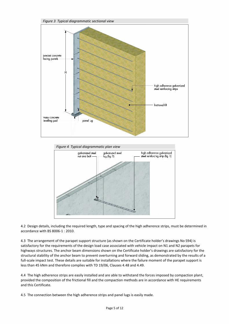
4 Use 4.1 When designed and installed in accordance with this Certificate, the high adherence strip and panel lugs are satisfactory for use in providing reinforcement for reinforced soil structures, with stability achieved through interaction of the soil particles with the high adherence strips. A typical sectional elevation and plan are shown in Figures 3 and 4, respectively.
Page 5 of 12
Figure 3 Typical diagrammatic sectional view
Figure 4 Typical diagrammatic plan view
4.2 Design details, including the required length, type and spacing of the high adherence strips, must be determined in
accordance with BS 8006-1 : 2010.
4.3 The arrangement of the parapet support structure (as shown on the Certificate holder’s drawings No S94) is
satisfactory for the requirements of the design load case associated with vehicle impact on N1 and N2 parapets for
highways structures. The anchor beam dimensions shown on the Certificate holder’s drawings are satisfactory for the
structural stability of the anchor beam to prevent overturning and forward sliding, as demonstrated by the results of a
full-scale impact test. These details are suitable for installations where the failure moment of the parapet support is
less than 45 kNm and therefore complies with TD 19/06, Clauses 4.48 and 4.49.
4.4 The high adherence strips are easily installed and are able to withstand the forces imposed by compaction plant,
provided the composition of the frictional fill and the compaction methods are in accordance with HE requirements
and this Certificate.
4.5 The connection between the high adherence strips and panel lugs is easily made.

Page 6 of 12
4.6 To prevent damage, the high adherence strips must not come into direct contact with compaction plant, they must
be covered and protected with frictional fill prior to any trafficking.
4.7 Fill should be placed to a minimum depth as detailed in the MCHW, Volume 1, Series 600 before each pass of the compaction plant and, to avoid movement of the precast concrete facing panels, heavy compaction plant should not be employed within 2 m of the face. 4.8 Prior to the commencement of the work, the designer must satisfy the design approval and certification procedure of the relevant Highway Authority.
4.9 Where appropriate to specific projects, the designer should provide the main contractor with details of:
• working drawings
• calculations
• specification for frictional fill
• acceptable moisture content of frictional fill at time of placement
• drainage
• protection of the high adherence strips and panel lugs against damage during installation
• design of the precast concrete facing panel units
• sequence of placing fill material
• estimated movement of precast concrete facing panel units during filling and compaction operations
• tolerance on the position of finished line of the wall.
4.10 Where appropriate, the reinforced soil structure should be protected against horizontal impact loads caused by possible vehicle collision with the lower precast concrete facing panel units of the wall.
4.11 The precast concrete facing panels should be designed to conform to the requirements of the Principles and Application Rules of Eurocode 2.
5 Practicability of installation The system components must be installed only by trained ground engineering contractors in accordance with the specifications and construction drawings.
6 Design 6.1 Reinforced soil structures incorporating the system must be designed in accordance with BS 8006-1 : 2010, HE requirements and the MCHW, Volume 1. 6.2 In accordance with BS 8006-1 : 2010, Annex B, the design of permanent walls and bridge abutments should have a design life of 120 years.
7 Mechanical properties Design strength (TD) 7.1 The appropriate design strength (TD) for a particular combination of high adherence strip and panel lug may be taken from Table 1, this allows for:
• a design life of 120 years
• a partial material factor (fm) of 1.5
• a partial factor (fn) of 1.1, dealing with ramifications of failure according to BS 8006 -1 : 2010.

Page 7 of 12
Notes:
• the design strength (TD) of metallic reinforcement should be: 𝑇𝐷= 𝑇𝑈/𝑓𝑚
where: 𝑇𝐷 is the design strength of the reinforcement 𝑇𝑈 is the ultimate tensile strength of the reinforcement 𝑓𝑚 is the partial material factor for reinforcement – for galvanized steel reinforcement, the value should be taken as (1.5)
• factor of safety for ramifications of failure for category 3 structures a partial safety factor of 1.1 is applied to the equation in accordance with BS 8006-1 : 2010
• sacrificial thickness : for 120 years design life for galvanized steel reinforcement reduction is 0.75 mm per face (Dry areas) and 1.0 mm per face (Fresh water/Wet areas), only if 6I and 6J materials are acceptable to Section 600 Earthworks of HE Specification Table 6/1
• for determination of long-term design strength (Dry Condition) calculation example: for taking account of the sacrificial thickness, the manufacturing tolerances and partial safety factors (fm and fn), the design strength of each strip type based on clause 6.8.4.3.2 of BS 8006 - 1 : 2010 𝑇𝐷= 510 / 1.5 * 1.1 = 309.09 N𝑚𝑚−2
• for 455 strip-cross section = strip size including manufacturing tolerances – (120 years sacrificial thickness ) = (44.5-0.75-0.75) x (4.8-0.75-0.75) = 141.9 mm2 - main body - or (39.5-13-0.75-0.75-0.75-0.75) x (7.8-0.75-0.75) = 148.05 mm2 (connection)
• design strength (455) strip = 43.86 kN (main body); *45.76 kN* (connection) but governed by panel lug strength
• for panel lug, allowable cross section = strip size including manufacturing tolerances minus 120 year sacrificial thickness = (44-13.7-0.75-0.75-0.75-0.75) x (4.0-0.75-0.75) = 68.25 mm2 x 2 = 136.5 mm2
• design strength of panel lug = 42.19 kN
• for determination of long-term design strength (Wet Condition) calculations example: allowable cross section of (455) strip = strip size including manufacturing tolerances minus 120 year sacrificial thickness = (44.5-1.0-1.0) x (4.8-1.0-1.0) = 119 mm2 (main body) or (39.5-13-1.0-1.0-1.0-1.0) x (7.8-1.0-1.0) = 130.5 mm2 (connection)
• design strength (455) strip = 36.78 kN (main body); *40.34 kN* (connection) but governed by panel lug strength.
High adherence strip/frictional fill interaction 7.2 The frictional fill material used in the structures must be 6I or 6J frictional fill, as described in the MCHW Volume 1, Section 600 Earthworks, Tables 6/1 and 6/2, with electrochemical properties in accordance with Table B.1 of BS 14475 : 2006, or frictional fill material as described in section 7.3 of this Certificate. 7.3 Frictional fill material used in structures that comply with the following grading limits (see Table 2), has a uniformity coefficient not less than two, and the characteristic parameters defined in section 7.4 can be used in design without further tests, except where the frictional fill is chalk, in which case shear box (300 mm) tests must be carried out. Where frictional fill in the reinforced earth structure is within a vertical distance of 1 m of a trafficked road surface, it must have a uniformity coefficient not less than 5.
Table 2 Fill material grading limits BS sieve Percentage passing
125 mm(1) 100
75 mm not less than 75
10 mm not less than 10
63 μm 0 to 15

Page 8 of 12
7.4 For frictional fill complying with the grading requirements of sections 7.2 or 7.3, shear strength characteristics(1) will be equal to or better than:
• ɸˊ = 36°, where ɸˊ is the effective angle of friction of the fill
• µ*0 = 1.2 + log (uniformity coefficient) and
• µ*6+ = tan ɸ’, where µ*
0 and µ*
6+ are defined in Figure 5 of this Certificate, and represent enhanced pull-out
resistance as described in clause 2.12 of BS 8006-1 : 2010
(1) These values are conservative and maybe used in routine design of structures in accordance with BS 8006-1 : 2010 and the MCHW, Volume 1, unless more definitive data on uniformity coefficient (CU) and ɸˊ are available. Particles from 125 mm and up to 250 mm maybe used at the discretion of the engineer.
Figure 5 Distribution of μ* values used for design
7.5 Definitive data for uniformity coefficient (CU) of the frictional fill can be obtained from particle size distribution tests (where CU = D60/D10 in accordance with BS EN ISO 14688 -2 : 2004). Definitive data for ɸˊ for the frictional fill can be obtained from shear box (300 mm) tests.
7.6 When the frictional fill has more than 15% passing the 63 micron sieve, special procedures are required for determining the suitability of the frictional fill. These are shown on drawing No S429 available from the Certificate holder. 7.7 Frictional fill material containing particles greater than 250 mm is not covered by this Certificate, but may be acceptable at the discretion of the engineer. The following provisions should be considered:
• the size of the largest particles is not greater than 70% of the vertical spacing of the high adherence strips
• the frictional fill is well graded
• frictional fill containing large particles is not placed within a distance of 2 m of the facing
• compaction of the frictional fill can be carried out to achieve the required density.
Parapet support structure 7.8 The parapet support units must be constructed to the design of the Certificate holder, as approved by the BBA and as shown in drawing Nos S94 and S98 available from the Certificate holder. The general arrangement is shown in Figure 6.

Page 9 of 12
Figure 6 Parapet support structure general arrangement
7.9 The number and layout of high adherence strips below the parapet support structure must be to the requirements of the Certificate holder, approved by the BBA and as shown on drawing No S94 available from the Certificate holder (see section 4.3). Precast concrete facing panels 7.10 The precast concrete facing panel units must be designed in accordance with the relevant provisions of BS 8006-1 : 2010, BS EN 14475 : 2006 and BS EN 1992-2 : 2005. 7.11 The appropriate combination of concrete exposure classes should be selected from Table A.1 of BS 8500-1 : 2015, and Table 1 of BS EN 206-1 : 2013, to suit the proposed location and level of exposure of the proposed structure. 7.12 Where precast concrete facing panel units are to be embedded in soils which could be potentially aggressive, the guidance in BRE Special Digest 1 : 2005, Part C should be followed. Connection strength 7.13 A full strength connection can be achieved between the high adherence strips and precast concrete facing panels using the method described in section 1.7. A reduction factor for connection strength is not required where high adherence strips and panel lugs are connected to the precast concrete facing panels in this manner.
8 Maintenance The exposed faces of the precast concrete facing panels may require occasional maintenance, to remove dirt build up, mould and moss growth. The other system components are confined within the frictional fill and do not require maintenance.
9 Durability 9.1 In the opinion of the BBA, when used and installed in accordance with this Certificate, the system can achieve a design life of 120 years, as required by BS 8006-1 : 2010. 9.2 The precast concrete facing panels will have adequate durability for the proposed life of the structure under exposure conditions normally encountered in the UK in reinforced earth retaining wall and bridge abutments, when designed and installed in accordance with the provisions of BS 8006-1 : 2010, BS EN 14475 : 2006 and the requirements of this Certificate (see sections 7.10 to 7.12).

Page 10 of 12
Installation
10 Procedure 10.1 The formation level is prepared, the concrete levelling pad constructed, and the first course of precast concrete facing panels erected and temporarily propped. 10.2 Frictional Fill is placed and compacted behind the facing up to the level of the first layer of high adherence strips. 10.3 The high adherence strips are then laid and attached to the panel lug embedded in the precast concrete facing panels, using galvanized steel connection bolts. 10.4 A further course of precast concrete facing panels are placed, and successive layers of frictional fill are placed and compacted on top of the high adherence strips until the level of the next layer of strips is reached. The sequence is repeated up to the required height of the structure. 10.5 The parapet support units are constructed using normal reinforced concrete construction techniques.
Technical Investigations
11 Tests As part of the assessment resulting in the issue of previous BBA Certificate 99/R106, tests were carried out to establish:
• thickness of galvanizing on high adherence strips and panel lugs
• coefficient of friction between high adherence strips and frictional fill
• performance of parapet support structure under full-scale impact test.
12 Investigations 12.1 As part of this and previous assessments, the following investigations were carried out:
• existing data on the high adherence strip were examined in relation to coefficient of friction between the strips and the frictional fill quality and composition of steel tensile properties of steel quality of galvanizing design calculations
• existing data on the panel lug were examined in relation to quality and composition of steel tensile properties of steel quality of galvanizing design of high adherence strip/panel lug connection
• existing data relating to the quality of the bolts were examined. 12.2 The manufacturing processes for the high adherence strip and panel lugs were examined, including the methods of quality control and details were obtained of the quality and composition of the materials used. 12.3 A visit was made to site to assess the practicability of installation. 12.4 Test data and design calculations relating to the parapet support units were examined. Additional information All suppliers of the High Adherence Strip and Panel Lug System components to the Certificate holder’s specification are required to have had their management systems assessed and registered as meeting the requirements of BS EN ISO 9001 : 2015.

Page 11 of 12
Bibliography BRE Special Digest 1 : 2005 Concrete in aggressive ground, Part C Assessing the aggressive chemical environment BS 3692 : 2014 ISO metric precision hexagon bolts, screws and nuts — Specification BS 8500-1 : 2015 + A1 : 2016 Concrete — Complementary British Standard to BS EN 206-1 — Method of specifying and guidance for the specifier BS 8006-1 : 2010 + A1 : 2016 Code of practice for strengthened/reinforced soils and other fills BS EN 206-1 : 2013 + A1 : 2016 Concrete — Specification, performance, production and conformity BS EN 1992-2 : 2005 Eurocode 2 — Design of concrete structures — Concrete bridges — Design and detailing rules BS EN 10025 -1 : 2004 Hot rolled products of structural steels — General technical delivery conditions BS EN 10025 -2 : 2004 Hot rolled products of structural steels — Technical delivery conditions for non-alloy structural steels BS EN 14475 : 2006 Execution of special geotechnical works — Reinforced fill BS EN ISO 898-1 : 2013 Mechanical properties of fasteners made of carbon steel and alloy steel — Bolts, screws and studs with specified property classes — Coarse thread and fine pitch thread BS EN ISO 898-2 : 2012 Mechanical properties of fasteners made of carbon steel and alloy steel —Nuts with specified property classes — Coarse thread and fine pitch thread BS EN ISO 1461 : 2009 Hot dip galvanized coatings on fabricated iron and steel articles — Specifications and test methods BS EN ISO 4014 : 2011 Hexagon head bolts — Product grades A and B BS EN ISO 4032 : 2012 Hexagon regular nuts (style 1) — Product grades A and B BS EN ISO 9001 : 2015 Quality management systems — Requirements BS EN ISO 14688-2 : 2004 + A1 : 2013 Geotechnical investigation and testing — Identification and classification of soil — Principles for a classification TD 19/06 Design Manual for Roads and Bridges (DMRB), Volume 2, Section 2, Part 8 Requirement for Road Restraint Systems Manual of Contract Documents for Highways Works (MCHW), Volume 1 Specification for Highways Works

Page 12 of 12
Conditions of Certification
13 Conditions 13.1 This Certificate:
• relates only to the product/system that is named and described on the front page
• is issued only to the company, firm, organisation or person named on the front page – no other company, firm, organisation or person may hold claim that this Certificate has been issued to them
• is valid only within the UK
• has to be read, considered and used as a whole document – it may be misleading and will be incomplete to be selective
• is copyright of the BBA
• is subject to English Law. 13.2 Publications, documents, specifications, legislation, regulations, standards and the like referenced in this Certificate are those that were current and/or deemed relevant by the BBA at the date of issue or reissue of this Certificate. 13.3 This Certificate will remain valid for an unlimited period provided that the product/system and its manufacture and/or fabrication, including all related and relevant parts and processes thereof:
• are maintained at or above the levels which have been assessed and found to be satisfactory by the BBA
• continue to be checked as and when deemed appropriate by the BBA under arrangements that it will determine
• are reviewed by the BBA as and when it considers appropriate. 13.4 The BBA has used due skill, care and diligence in preparing this Certificate, but no warranty is provided. 13.5 In issuing this Certificate the BBA is not responsible and is excluded from any liability to any company, firm, organisation or person, for any matters arising directly or indirectly from:
• the presence or absence of any patent, intellectual property or similar rights subsisting in the product/system or any other product/system
• the right of the Certificate holder to manufacture, supply, install, maintain or market the product/system
• actual installations of the product/system, including their nature, design, methods, performance, workmanship and maintenance
• any works and constructions in which the product/system is installed, including their nature, design, methods, performance, workmanship and maintenance
• any loss or damage, including personal injury, howsoever caused by the product/system, including its manufacture, supply, installation, use, maintenance and removal
• any claims by the manufacturer relating to CE marking. 13.6 Any information relating to the manufacture, supply, installation, use, maintenance and removal of this product/system which is contained or referred to in this Certificate is the minimum required to be met when the product/system is manufactured, supplied, installed, used, maintained and removed. It does not purport in any way to restate the requirements of the Health and Safety at Work etc. Act 1974, or of any other statutory, common law or other duty which may exist at the date of issue or reissue of this Certificate; nor is conformity with such information to be taken as satisfying the requirements of the 1974 Act or of any statutory, common law or other duty of care.
British Board of Agrément Bucknalls Lane Watford Herts WD25 9BA
©2018
tel: 01923 665300
[email protected] www.bbacerts.co.uk