reinforced concrete partition walls retrofitted with...
TRANSCRIPT

Reinforced Concrete Partition Walls Retrofitted with Carbon Fiber Reinforced Polymer
Shyh-Jiann Hwang1, Yaw-Shen Tu2, Yung-Hsin Yeh3, and Tsung-Chih Chiou3
ABSTRACT
For seismically insufficient buildings, retrofitting of the reinforced concrete partition walls using the
carbon fiber reinforced polymer is of particular interest at the present juncture in Taiwan after Chi-Chi Earthquake. This paper describes theoretical and experimental studies related to the seismic retrofits of the reinforced concrete frames containing partition walls using carbon fiber reinforced polymer materials. One “as built” partition wall, one structural wall, and four “retrofitted” partition walls had been tested under simulated seismic actions. The test results of the retrofitted partition walls indicated that the use of the carbon fiber reinforced polymer with sufficient end anchorages is an effective retrofitting measure. Experimental observations and theoretical analyses indicated that the shear resisting mechanism of the reinforced concrete squat walls can be modeled as the strut-and-tie actions, and that the shear strength of low-rise wall can be reasonably predicted by the softened strut-and-tie model.
1 Professor, Dept. of Construction Engineering, National Taiwan University of Science and Technology,
Taipei, Taiwan 10672, ROC
Division Head of Building Structures, National Center for Research on Earthquake Engineering, Taipei, Taiwan 106, ROC
2 Lecturer, Department of Civil Engineering, De Lin Institute of Technology, Taipei, Taiwan 23654, ROC
PhD Candidate, Dept. of Construction Engineering, National Taiwan University of Science and Technology, Taipei, Taiwan 10672, ROC
3 Research Assistant Fellow, National Center for Research on Earthquake Engineering, Taipei, Taiwan 106, ROC

INTRODUCTION
The poor performances of the low-rise reinforced concrete (RC) buildings with nonductile reinforcing details had been widely observed during the Chi-Chi earthquake. This stimulates an urgent need of seismic assessment and retrofitting of these structures. However, seismic retrofitting of each component of the nonductile RC frames is extremely difficult and expensive. Fortunately, the existing low-rise buildings in Taiwan contain a lot of partition walls which are lightly reinforced RC walls. By retrofitting these walls as the lateral-force-resisting elements, the existing frames can be treated as members that are not proportioned to resist forces induced by earthquake motions. This retrofitting strategy may alleviate the strength and deformation requirements of a nonductile RC frame. Due to the greatly reduced cost, the retrofitting of the existing buildings with nonductile frames is much feasible.
The low-rise buildings in Taiwan were usually designed as structural frames, but nevertheless the interaction of frames and partition walls due to earthquakes was not considered in the analysis. Therefore, the RC frames were provided with sufficient strengths, but the partition walls were detailed with temperature and shrinkage reinforcement only. Consequently, the frames containing RC partition walls might result in sufficient flexural strength but unfortunately insufficient shear strength. The common practice in Taiwan now is to tear down the partition walls then to recast with the RC structural walls. This retrofit scheme is time consuming and causes tremendous inconvenience to the residents. Seeking for the other alternative is of ever-increasing expectance.
The repair of understrengthed or damaged reinforced concrete members by the external bonding of carbon fiber reinforced polymer (CFRP) laminates is becoming increasingly popular in the construction industry (Meier 1992). The use of CFRP laminates for this application offers several desirable attributes, such as high strength, resistance to corrosion, light weight, and ease of handling. Retrofitting the RC partition walls by the bonding of CFRP might be a feasible solution of the aforementioned problem.
This paper describes theoretical and experimental studies related to the seismic retrofits of the RC frames containing partition walls using CFRP materials. Experimental tests (Yeh 2001, Chiou 2002) were conducted on wall specimens that were subjected to reversed cyclic inelastic deformations representative of earthquake loadings. Theoretical analyses, based on the softened strut-and-tie model (Hwang and Lee 2002) and the ACI 318 building code (2002), were performed to evaluate the shear strength of the walls. RESEARCH SIGNIFICANCE
The techniques on assessment and retrofitting of the seismically insufficient buildings are urgently needed in Taiwan. This paper presents the experimental and analytical studies related to the seismic retrofits of the RC frames containing partition walls using CFRP materials. The test results indicate that the use of the CFRP laminates with sufficient end anchorages is quite effective in enhancing the shear strength of partition walls. Moreover, the enhanced shear strength of the retrofitted walls can be reasonably assessed by the softened strut-and-tie model.

EXPERIMENTAL PROGRAM Test Specimens
In all, six large-scale isolated specimens, two as-built walls and four retrofitted walls, were tested. The test specimens are identified as WF-12, WF-12-FV, WF-12-FHV, WF-12-FV-A, WF-12-FHV-A, and WF-15. The dimensions and reinforcing details are given in Fig. 1. In order to focus attention on the shear behavior of walls, the adequate strength and the ductile detailing requirements per ACI 318 building code (2002) were adopted for the design of frames for all specimens.
The test wall of Specimen WF-12 (Yeh 2001) represented approximately 0.6 scale model of a prototype partition wall in a building. The test wall was 12 cm thick with 5030 × cm boundary elements. The overall length of the wall was 350 cm and the height was 155 cm. Specimen WF-12 had reinforcement #3 @ 30cm for each direction placed in one layer parallel with faces of wall (Fig. 1), which resulted in the minimum ratio of reinforcement area to gross concrete area of 0.002.
Clear (typ.)
unit: cm
4150
4 4
44
32
#3@
30fo
r WF-
12
2-#4
@20
for W
F-15
10-#6
30
422
50
#4@8
8-#6 #4@10
#4@15
18-#8
Section A-A
AA
B
B
Section B-B
4063
405015
570
42
#3@30 for WF-122-#4@20 for WF-15
4424 Clear (typ.)
250 505025 25
412 for WF-12; 15 for WF-15
Figure 1. Geometry and reinforcement detail
Specimens WF-12-FV and WF-12-FHV (Yeh 2001) had the same existing wall dimensions as
WF-12 but retrofitted with CFRP laminates. Specimen WF-12-FV was strengthened with four layers of vertical CFRP laminates, two layers for each side of wall. The fibers of CFRP laminates for Specimen WF-12-FV were placed in the vertical direction and the thickness of each layer is 0.1375 mm. Total of eight layers of CFRP laminates were bonded to Specimen WF-12-FHV, four layers in the horizontal direction and four layers in the vertical direction. One layer of the CFRP laminate with the horizontal fibers was first bonded to the wall web, and then one layer of the vertical laminate was added in turn. In order to reflect the real situations in fields, the CFRP sheets were attached to Specimens WF-12-FV and

WF-12-FHV without the end anchorage. The CFRP sheets were terminated at the edges of wall web. This might cause two serious drawbacks. Firstly, delamination might easily occur in the vicinity of the edges of CFRP sheet. Secondly, the interface shear capacity at the wall base is not improved since the CFRP laminates without end anchorage cannot be treated as interface shear reinforcement.
Specimens WF-12-FV-A and WF-12-FHV-A (Chiou 2002) had the same properties as those of Specimens WF-12-FV and WF-12-FHV, except that the end anchorages of the CFRP laminates were carefully installed for Specimens WF-12-FV-A and WF-12-FHV-A. As shown in Fig. 2, the vertical CFRP sheets were anchored at the wall base and the reaction beam through a load transfer mechanism to transfer the load carried by the CFRP sheets to the supports of the specimen. The anchor system consists of a structural steel angle bolted to the supports of the specimen (Fig. 2). More details can be found in References (Chiou 2002 and Lombard 1999 ). The horizontal CFRP sheets were wrapped around the wall web with a lap length of 20 cm, as seen in Fig. 2.
Lafas et al.(1990) found that horizontal web reinforcement does not appear to have a significant effect on the shear resistance of a low-rise wall. In view of this contrasting evidence, Specimen WF-12-FV-A, bonded with the vertical CFRP sheets only, was designed to clear this ambiguity.
Specimen WF-15 (Chiou 2002) contains a structural wall of thickness of 15 cm, which provided a threshold of the qualified wall behavior. Two curtains of #4 reinforcement spacing at 20 cm were used in Specimen WF-15 (Fig. 1). The vertical and horizontal reinforcement in the wall of Specimen WF-15 was approximately 0.5 percent of the wall cross section.
30
30
25
5
25
2
B
B
AA
155
5070
Section B-B
12
40
unit: cm
Cement grout
WallEpoxyCFRP
Section A-A
30
18
9
Radius 3
50 250 50
Lap > 20 CFRP
Bolt (M16)
17 Base block
Wall
Bolt (M20)
Detail C
Angle
Detail C
Beam
Base block
Col
umn
Col
umn
(L150 100 10)× ×
Figure 2. Details of end anchorage of CFRP
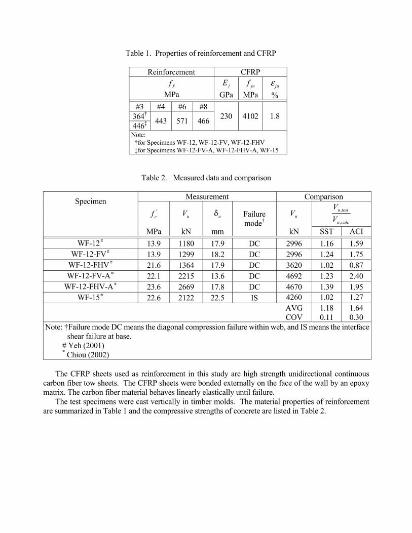
Table 1. Properties of reinforcement and CFRP
Reinforcement CFRP yf
MPa jE
GPa juf
MPa juε
% #3 #4 #6 #8
364†
446‡ 443 571 466 230 4102 1.8
Note: †for Specimens WF-12, WF-12-FV, WF-12-FHV ‡for Specimens WF-12-FV-A, WF-12-FHV-A, WF-15
Table 2. Measured data and comparison
Measurement Comparison
'cf uV uδ nV
calcu
testu
VV
,
,
Specimen
MPa kN mm
Failure mode†
kN SST ACI WF-12# 13.9 1180 17.9 DC 2996 1.16 1.59
WF-12-FV# 13.9 1299 18.2 DC 2996 1.24 1.75 WF-12-FHV# 21.6 1364 17.9 DC 3620 1.02 0.87 WF-12-FV-A* 22.1 2215 13.6 DC 4692 1.23 2.40
WF-12-FHV-A* 23.6 2669 17.8 DC 4670 1.39 1.95 WF-15* 22.6 2122 22.5 IS 4260 1.02 1.27
AVG 1.18 1.64 COV 0.11 0.30
Note: †Failure mode DC means the diagonal compression failure within web, and IS means the interface shear failure at base.
# Yeh (2001) * Chiou (2002)
The CFRP sheets used as reinforcement in this study are high strength unidirectional continuous
carbon fiber tow sheets. The CFRP sheets were bonded externally on the face of the wall by an epoxy matrix. The carbon fiber material behaves linearly elastically until failure.
The test specimens were cast vertically in timber molds. The material properties of reinforcement are summarized in Table 1 and the compressive strengths of concrete are listed in Table 2.

Test Setup and Procedure The overall schematic representation of the test setup is shown in Fig. 3(a). Horizontal load was
applied with three double-acting servo-controlled actuators, 1000-kN capacity each. The top reaction beams of the test specimens were clamped with two steel beams to simulate the mechanism that the lateral load is transferred from the strong diaphragm (Fig. 3). The footing was tied down to the test floor with 8 post-tension rods, and the horizontal movement of the footing was further restrained by two end reaction blocks. Fig. 3(b) presents the photo of the test setup in this study.
(a) Schematic representation of the test setup
(b) Photo of test setup
Prestressed rod800kN
40 40 40 40 4060
Strong floor
400
60
100
Wedge steel plate
Steel plate
Reactionblock
Clamp beam
Measurement of
Prestressed rod 900kN
Unit: cm
deflection δ
Figure 3. Test setup
Drif
t rat
io (%
)
Figure 4. Loading history

The wall specimens were tested to failure in the in-plane direction subjected to a predetermined increasing quasi-static cyclic loading. The loading pattern for the specimens consisted of two cycles at lateral drift ratios, as shown in Fig. 4.
OBSERVERD BEHAVIOR
Horizontal force-displacement hysteretic response histories and final damage patterns for all specimens are shown in Fig. 5. Horizontal shear forces (V ) were measured by calibrated load cells in actuators. Top horizontal displacements (δ ) were measured by linear potentiometers, as shown in Fig. 3(a). The failure mode of all the specimens, except WF-15, was the diagonal compression failure in the wall web due to shear. Specimen WF-15 was failed due to the interface shear at base, as shown in Fig. 5(f). It is noted that, for Specimen WF-12-FV-A as shown in Fig. 5(d), crushing of concrete was found in the upper half of column. Honeycombs existed in that spot due to improper handling of concrete during placement. This is a post-strength damage and Specimen WF-12-FV-A was failed by the crushing of concrete in the wall web. No damage was found for the end anchorage systems of Specimens WF-12-FV-A and WF-12-FHV-A.
Table 2 reports the measured shear strength, uV , as well as the calculated shear corresponding to the flexural nominal strength at the base of wall, nV . The flexural nominal strengths of the test specimens, subjected to single curvature bending, were determined by analysis of the fully cracked section with straight-line theory. The maximum force-carrying capacities uV developed by all the wall specimens were less than the calculated shear due to flexure nV (Table 2), indicating insufficient shear strengths of the wall specimens.
In disregard of the retrofitting with CFRP laminates, Specimens WF-12, WF-12-FV and WF-12-FHV exhibited similar hysteretic behavior. This can be examined through their hysteretic curves in Figs. 5(a)-5(c) and other indices, such as shear strength and failure mode, shown in Table 2. This observation clearly indicates that bonding the CFRP sheets to the wall webs without end anchorage system is worthless. The ACI 318 building code (2002) requires that all continuous reinforcement in structural walls shall be anchored and developed fully during an earthquake. For strengthening, the CFRP laminates bonded on the surface of wall behave like reinforcement. Therefore, the full anchorage of the CFRP sheets is required.
On the other hand, the shear strengths of Specimens WF-12-FV-A and WF-12-FHV-A were significantly enhanced (Fig. 5). Compared to Specimen WF-12, the application of the CFRP sheets resulted in 88% and 126% increase in the shear strengths for Specimen WF-12-FV-A and WF-12-FHV-A (Table 2), respectively. The enhanced shear capacities can substantiate the necessity of the end anchorage for the application of the CFRP laminates.
As comparing the measured shear strengths among Specimens WF-12, WF-12-FV-A and WF-12-FHV-A, a strength increase of 88% is attributable to the bonding of the vertical CFRP sheets, and a further increase of 38% is accountable for the addition of the horizontal CFRP laminates. It is clearly shown that, for the test walls with a height-to-width ratio of 0.51, retrofitting with the vertical CFRP sheets is more efficient in enhancing the shear strength. That the ACI 318 building code (2002) emphasizes the detailing of the horizontal web reinforcement is indeed misleading.

Specimen WF-15 had the shear strength higher than that of Specimen WF-12, but was failed due to the interface shear in stead of the web diagonal compression (Fig. 5). It means that, for Specimen WF-15, the larger volume of concrete and increased amount of steel in web can enhance the web crushing strength more efficiently than the interface shear capacity. As compared to Specimen WF-15, Specimens WF-12-FV-A and WF-12-FHV-A had higher strengths and different failure mode of web crushing. This reveals that the application of the vertical CFRP sheets with end anchorages can increase the interface shear capacity at base.
Figure 5. Load-deflection responses and final damage patterns

She
ar fo
rce
(kN
)
Figure 6. Envelopes of load-deflection responses
Fig. 6 shows the envelopes of load-deflection response for all specimens. As revealed in Fig. 6, the
retrofitted specimens WF-12-FV-A and WF-12-FHV-A developed much higher strengths than the as-built walls WF-12 and WF-15. The test results indicated that the retrofit of RC partition walls by the external bonding of CFRP laminates with sufficient end anchorage is quite effective.
The shape of envelope of the diagonal compression failure is different from that of the interface shear failure (Fig. 6). The load-deflection curve of diagonal compression failure descends quickly from the peak value, whereas the curve of envelope of the interface shear failure decreases slowly. It is of interest to note that the walls with diagonal compression failure can have a residual strength exceeding a half of the peak strength and can maintain this residual value until a drift ratio of 3% (Fig. 6). This piece of information might be useful for the seismic assessment of the low-rise RC buildings.
ASSESSMENT OF WALL SHEAR STRENGTH Softened Strut-and-Tie Model
A rational model for determining the shear strength of RC walls for seismic resistance has been
developed by Hwang et al. (2001). The proposed model, termed as the softened strut-and-tie (SST) model, is based on the concept of struts and ties and derived to satisfy equilibrium, compatibility, and constitutive law of cracked reinforced concrete.
Three strut-and-tie load paths (Hwang et al. 2001) are proposed to model the force transfer within the wall, and they are the diagonal, horizontal, and vertical mechanisms as depicted in Fig. 7. The diagonal mechanism is a diagonal compression strut. The vertical mechanism includes one vertical tension tie and two steep compression struts, and the horizontal mechanism is composed of one horizontal tension tie and two flat compression struts. For diagonal compression failure, the shear strength of the wall is defined as the concrete compressive stress on the nodal zone reaching its capacity. The softened strut-and-tie model was found to reproduce the available test results of shear walls from the literature with reasonable accuracy (Hwang et al. 2001).
In order to facilitate the routine design, a simplified approach of the softened strut-and-tie model was also developed (Hwang and Lee 2002). It is found that the simplified model is a useful and practical tool for determining the shear strength of the walls failing in diagonal compressions.

ba
3ba
h
wa 3wa
HvF
D
hF
h
rvd
θ
θ
T C
V
wtn
bbbh
nH
Figure 7. Strut-and-tie modeling for cracked wall
Evaluation of Shear Strength
The shear strength of low-rise RC walls failing in diagonal compressions can be estimated using the simplified version of the softened strut-and-tie model (Hwang and Lee 2002).
θζ cosstrcu AfKV ′= (1) where K is the strut-and-tie index; cf ′ is the compressive strength of a standard concrete cylinder in units of MPa; strA is the effective area of the diagonal strut; θ is the angle of inclination of the diagonal strut with respect to the horizontal h axis (Fig. 7); and ζ is the softening coefficient. The solution algorithm for uV is summarized in Fig. 8. More details can be found in References (Hwang et al 2004 ).
In the softened strut-and-tie model, the CFRP laminates can be model as tension tie to enhance the shear strength of walls. Since the CFRP sheet without end anchorage is useless, the effect of CFRP was excluded from the estimation for Specimens WF-12-FV and WF-12-FHV. For Specimens WF-12-FV-A and WF-12-FHV-A, the bonded CFRP sheets are treated as reinforcement with a design tensile strain of 0.002 (Yu and Hwang 2004) in calculating the strut-and-tie index K .
The failure mode of Specimen WF-15 was classified as interface shear failure. However, the prediction of the interface shear capacity for walls is unclear and not within the scope of this study. Therefore, the calculated strength for Specimen WF-15, listed in Table 2, is the diagonal strength estimated by the softened strut-and-tie model (Hwang and Lee 2002).
The shear strengths of test walls calculated using the softened strut-and-tie model (Hwang and Lee 2002) and the ACI 318 method (2002) are listed in Table 2. The average strength ratio ( calcutestu VV ,, / ) for the softened strut-and-tie model is 1.18 with a coefficient of variation of 0.11 (Table 2). The mean value and the coefficient of variation of the test-to-calculated shear strength ratio by ACI 318 method were found to be 1.64 and 0.30, respectively (Table 2). As seen in Table 2, the softened strut-and-tie model

(Hwang and Lee 2002) predicts the failure shears more accurately than the equation of the ACI 318 building code (2002).
Because the vertical reinforcement plays no role in the strength estimation of walls according to the ACI 318 building code (2002), a test-to-calculated strength ration of 2.40 was obtained for Specimen WF-12-FV-A (Table 2). This underestimation results from the inadequate force transfer mechanism adopted by the ACI 318 building code (2002). On the contrary, the softened strut-and-tie model yielded a reasonable strength ratio of 1.23 for Specimen WF-12-FV-A (Table 2). This is an evidence that the softened strut-and-tie model can reflect more correctly the shear failure mode of concrete crushing in the wall web, and that the revision on wall strength of the ACI 318 building code is needed.
52.035.3'
≤=ζcf
1−+= vh KKK
'cf wayhF yvF, , ,
2)7(
51 n
wnbbwn
bb
Hthb
tHh
a ≤+=
22bwwstr aatA +×=
⎟⎟⎠
⎞⎜⎜⎝
⎛ −= −
n
baH 3/tan 1θ
)(2.011 ;
)(2.011
22vv
vhh
h KKγ+γ−
=γ+γ−
=
31cot2 ;
31tan2 −θ=γ−θ=γ vh
θAfKF strhhh cos 'cζγ=
θAfKF strvvv sin 'cζγ=
v
v
yvvvh
h
yhhh K
FF
KKKFF
KK ≤−+=≤−+= )1(1 ;)1(1
θζ cos 'strcu AfKV =
Figure 8. Flow chart for shear strength at failure

As an improvement to current wall retrofit design methodology, it is recommended that the softened strut-and-tie model be used to assess the shear strength of RC walls, and that the seismically insufficient RC partition walls be retrofitted by using CFRP materials.
CONCLUSIONS Based on the cyclic load tests of 6 wall specimens, and within the limitations of the test data, the following conclusions are made:
1. The test results indicated that the externally bonded CFRP laminates with sufficient end anchorages is an effective retrofitting measure to enhance both the diagonal compression strength and the interface shear strength of RC walls. On the other hand, the application of the CFRP sheets without anchor system is worthless.
2. The diagonal compression strength of RC walls can be reasonably predicted by the softened strut-and-tie model. The CFRP sheets can be treated as reinforcement in shear resisting mechanism.
3. For the strengthening of the shear strength of the low-rise walls, the use of the vertical CFRP sheets is more effective than the application of the horizontal CFRP laminates. The empirical expressions on shear strength of walls of the ACI 318 building code are misleading and should be revised.
4. The residual strength of the low-rise RC wall subjected to diagonal compression failure descends quickly but maintains a value exceeding a half of the peak strength until a drift ratio of 3%.
ACKNOWLEDGMENTS
This research study was sponsored by both the National Science Council and the National Center for Research on Earthquake Engineering of the Republic of China. The authors would like to express their gratitude for the supports. Prof. K. C. Chang is specially thanked for his initiation and coordination of this research project
.
REFERENCES American Concrete Institute (ACI), 2002, Building Code Requirements for Structural Concrete, ACI 318-02 and Commentary (ACI 318R-02), Farmington Hills, Michigan. Chiou, T. C., 2002, “Reinforced concrete squat walls retrofitted with carbon fiber reinforced polymer,” Master Thesis, Department of Construction Engineering, National Taiwan University of Science and Technology (in Chinese). Hwang, S. J., Fang, W. H., Lee, H. J., and Yu, H. W., 2001, “Analytical model for predicting shear strengths of squat walls,” Journal of Structural Engineering, ASCE, Vol. 127, No. 1, January, pp. 43-50. Hwang, S. J., and Lee, H. J., 2002, “Strength prediction for discontinuity regions by softened strut-and-tie model,” Journal of Structural Engineering, ASCE, Vol. 128, No. 12, December, pp. 1519-1526.
Hwang, S. J., Tu, Y. S., and Yu, H. W., 2004, “Load deflection responses of low rise reinforced concrete shear walls,” submitted to Journal of Structural Engineering, ASCE. Lefas, I. D., Kotsovos, M. D., and Ambraseys, N. N., 1990, “Behavior of reinforced concrete structural walls: strength, deformation characteristics, and failure mechanism,” ACI Structural Journal, Vol. 87, No. 1, pp. 23-31. Lombard, J. C., 1999, “Seismic strengthening and repair of reinforced concrete shear wall using externally bonded carbon fiber tow sheets,” Master Thesis, Department of Civil and Environmental Engineering, Carleton University, Ottawa, Ontario, Canada. Meier, U., Deuring, M., Meier, H., and Schwengler, G., 1992, “Strengthening of structures with CFRP laminates: research and applications in Switzerland,” Proceedings of the 1st International Conference on Advanced Composite Material in Bridges and Structures, Sherbrooke, Quebec, pp. 243-251. Oesterle, R. G., Aristizabal-Ochoa, J. D., Shiu, K. N., and Corley, W. G., 1984, “Web crushing of reinforced concrete structural walls,” ACI Journal, Vol. 81, No. 3, May-June, pp. 231-241. Yeh, Y. H., 2001, “Reinforced concrete walls retrofitted with carbon fiber reinforced polymer,” Master Thesis, Department of Construction Engineering, National Taiwan University of Science and Technology (in Chinese). Yu, H. W., and Hwang, S. J., 2004, “Shear and flexural strength predictions for reinforced concrete beams using FRP laminates,” Journal of the Chinese Institute of Civil and Hydraulic Engineering, Vol. 16, No. 1, pp. 125-135 (in Chinese).