reflectance and illumination estimation for realistic ... and illumination estimation for... ·...
TRANSCRIPT

HAL Id: hal-01355581https://hal.inria.fr/hal-01355581
Submitted on 23 Aug 2016
HAL is a multi-disciplinary open accessarchive for the deposit and dissemination of sci-entific research documents, whether they are pub-lished or not. The documents may come fromteaching and research institutions in France orabroad, or from public or private research centers.
L’archive ouverte pluridisciplinaire HAL, estdestinée au dépôt et à la diffusion de documentsscientifiques de niveau recherche, publiés ou non,émanant des établissements d’enseignement et derecherche français ou étrangers, des laboratoirespublics ou privés.
Reflectance and Illumination Estimation for RealisticAugmentations of Real Scenes
Salma Jiddi, Philippe Robert, Eric Marchand
To cite this version:Salma Jiddi, Philippe Robert, Eric Marchand. Reflectance and Illumination Estimation for RealisticAugmentations of Real Scenes. IEEE Int. Symp. on Mixed and Augmented Reality, ISMAR’16(poster session), Sep 2016, Merida, Mexico. �hal-01355581�

Reflectance and Illumination Estimation for Realistic Augmentations ofReal Scenes
Salma Jiddi∗
Technicolor R&D FranceIRISA
Philippe Robert†
Technicolor R&D FranceEric Marchand‡
Universite de Rennes 1IRISA
Figure 1: Left: Original captured image of the scene. Center: Augmented scene with two virtual cubes. One can notice the effect of theestimated 3D position of the light source. Right: Augmented scene with a virtual sphere where the specular occlusion is correctly rendered.
ABSTRACT
The acquisition of surface material properties and lighting condi-tions is a fundamental step for photo-realistic Augmented Reality(AR). In this paper, we present a new method for the estimationof diffuse and specular reflectance properties of indoor real staticscenes. Using an RGB-D sensor, we further estimate the 3D posi-tion of light sources responsible for specular phenomena and pro-pose a novel photometry-based classification for all the 3D points.Our algorithm allows convincing AR results such as realistic virtualshadows as well as proper illumination and specularity occlusions.
Index Terms: I.4.1 [Image Processing and Computer Vision]:Digitization and Image Capture—Reflectance; I.4.8 [Image Pro-cessing and Computer Vision]: Scene Analysis—Photometry;
1 INTRODUCTION
The Augmented Reality field is expected to exhibit a high growthin the years to come. The ability of augmenting real scenes withsubjective virtual objects offers a large range of applications in var-ious domains such as training, entertainment and user assistance.Therefore, many research streams focus on delivering highly accu-rate and robust techniques for the AR essential algorithms such astracking, 3D reconstruction and photometry. As defined in [3], pho-tometric reconstruction is the process of estimating the illuminationand surface reflectance properties of an environment, given a geo-metric model of the scene and a set of photographs of its surfaces.Photometric and geometric reconstruction have often been consid-ered separately. The existing solutions often addressed scenes withsimple geometry (e.g. a plane) and reflectance (e.g. Lambertian ornon-textured surfaces) as well as scenes reduced to an isolated sin-gle object. For complex lighting, a mirror ball [9] or a fisheye cam-era [5] is generally introduced in the scene to capture the lighting.The recent development of RGB-D sensors (Google Tango tablet,Intel RealSense sensors, Microsoft Kinect, etc.) have moved geom-
∗e-mail: [email protected] , [email protected]†e-mail:[email protected]‡e-mail:[email protected]
etry and photometry closer providing new possible approaches tothe subject. In this paper, we are interested in estimating the dif-fuse and specular components which can spatially vary in texturedreal scenes. Also, we aim at recovering the 3D position of existinglight sources without using any light probes or external assistance.We only consider as input the RGB-D data provided by a given 3Dsensor. This paper makes four key contributions:
• Recovery of the spatially varying diffuse and specular proper-ties for the 3D scene.
• Estimation of the 3D position of point light sources using onlyobserved specular reflections in the scene.
• Photometry-based classification of all 3D points (shadowedareas, Lambertian and/or specular surfaces).
• Cast shadows detection and removal within the recovered dif-fuse component map.
2 RELATED WORK
Illumination and reflectance estimation is one of the most challeng-ing problems in the computer vision field. It requires fitting a Bidi-rectional Reflectance Distribution Function (BRDF) to the color in-tensity in the input RGB images. In this task, also called InverseRendering, simple lighting and reflection models have been consid-ered [10][13]. To address this problem, a wide variety of techniqueshave been developed. They are based on one or multiple images andscene geometry must be known (at least roughly). They can differfrom each other through the type of addressed scenes and acquireddata about the scene.
In [8], Nishino et al. proposed a method to separate the re-flectance components in the input images based on the pixel’s in-tensity variation using both sparse images and a geometric model.They considered only an isolated single object and assumed a uni-form specular reflectance property as well as distant light sources.Sato et al. [11] proposed a method that estimates the illuminationdistribution of a simple scene with shadows cast by an object usinga single color image of the scene. Practically, the image does notdisplay specular effects, so the method is mainly based on the shad-ows and alternates reflectance estimation and illumination radiance

estimation. The reconstructed data is only valid over a small regionof the scene due to the hemispherical nature of the resulting illumi-nation model. Gibson et al. [3] addressed the same problem in lessrestricted situations. They considered virtual light sources whichmimic the effect of direct and indirect illumination. The intensityof these virtual light sources and the surface material properties areestimated using an iterative algorithm which attempts to match cal-culated radiance values to those observed in photographs. Jachniket al. [4] presented an algorithm which is able to capture a surfacelight-field from a single hand-held camera by moving it around aspecular planar object. In [4], the captured surface light-field wassplit into its diffuse and specular components and used the specularreflection to estimate an environment map.
Several methods are based on intrinsic image decompositiontechniques. Their objective is to separate an image into its re-flectance and shading components. The reflectance componentcontains the intrinsic color (albedo) of depicted surfaces while theshading component encodes the incident illumination in the scene,shadows and shading. Lee et al. [6] presented a technique to solvethis under-constrained problem using an RGB-D sequence. Theyused both local and non-local, shading and temporal constraints,and obtained interesting intrinsic-images based decomposition re-sults. Neverova et al. [7] presented an approach which consists indecomposing an original image into its specular shading, diffuseshading and albedo. The obtained specular and diffuse shadingsrepresent the inputs of an optimization process aiming at findingthe 3D position of the light sources. In [6] and [7], no further es-timation of the specular parameters is proposed as they are eitherprocessed as an outlier or simply integrated in the shading.
Further methods have taken advantage of the RGB-D informa-tion available throughout single, sparse, or dense streams. Knechtet al. [5] proposed a method that reconstructs the surrounding en-vironment and then estimates its BRDF properties. They used botha Kinect sensor to acquire the scene’s geometry and a fisheye cam-era to capture the incident illumination. They assumed a uniformmaterial property for the recovered scene clusters, detected specu-lar effects as highlights in the image and did not consider shadowsfor the diffuse component estimation. Recently, Boom et al. [1]proposed a method to estimate surface reflectance and illuminationproperties for a real static scene using a 3D sensor. Following acolor-based segmentation on the assumed Lambertian surfaces, thealgorithm estimates a single albedo for each cluster and recoversthe 3D position of one light source only.
3 ALGORITHM OVERVIEW
Our method is an offline photometric analysis of 3D real scenes.We use a calibrated Kinect sensor to capture the scene under vari-ous viewing angles in order to bring out specular and diffuse reflec-tions. We estimate the camera positions using Mutual Information[2] and register the entire sequence with regard to a reference framein order to continuously locate 3D points. For every tracked pixel,we recover a spatio-temporal color profile which retains the vari-ations of the color intensity. We propose a statistical method toclassify these profiles and recover both, view-independent (diffuse)reflectance and view-dependent (specular) reflectance components.Futhermore, we estimate the 3D position of light sources respon-sible for specular effects and provide a photometry-based classi-fication of the 3D points of the scene to distinguish between sur-faces (shadowed areas, Lambertian and/or specular surfaces). Ouralgorithm deals with a variety of scenes where the texture spatiallyvaries and several geometry shapes can be present. We use our esti-mates to demonstrate specular occlusions between real and virtualobjects as well as realistic virtual shadows (Fig. 1). In terms ofassumptions, the scene and the lighting are supposed to be static.Only the sensor moves. The 3D model of the scene is retrievedusing depth maps but no necessary reconstruction is needed within
our algorithm pipeline. The light sources are supposed to be sparseand are modeled as point lights. Therefore, only one light sourcecreates a specular effect at a time.
4 METHOD
4.1 Sequence registration and spatio-temporal colorprofiles recovery
The sensor provides both RGB (Fig. 3-a) and depth streams at 30Hzwith a 640×480 pixel resolution. Our first objective is to extractcolor profiles of the observed scene points through the sequence.This requires tracking all pixels over the sequence. Practically, thisis achieved by registering the images with regard to a reference oneusing the camera poses and the depth maps. In order to obtainhighly accurate results, we implemented a three-pass registrationprocedure: first, we use a robust homography estimator [2] (MI isused as a similarity metric due to the presence of specular effects),recover the camera’s 3D position and then use it to register all RGBimages.
In the following, we will equally talk about the pixels of the ref-erence image and the 3D scene points they correspond to. Con-sidering all the sequence frames, we are able to track and estimatethe intensity variations of a given pixel. These variations consitutea spatio-temporal color profile to which we will refer as the Re-flectance Profile (RP). Practically, our set of registered images pro-vides for each 3D point/pixel observed in the reference frame theevolution of its color along the video, described by Ip(x,t), wherex is the constant 2D location of point p in the images, and t is theindex of the image in the sequence. A particular curve is retrievedfor each pixel p and corresponds to a linear combination of the threeRGB color channels. Various and differently shaped profile curvescan be obtained (Fig. 2). For instance, if the values of the profilesignificantly vary, the 3D point is bound to belong to a specular sur-face.We have observed three main cases where a 3D point p holdsan invariant profile: (1) p is purely diffuse and never exhibits specu-lar effects in spite of the presence of incident lighting; (2) the pointis not subject to specular effects because no light source contribu-tion was captured along the browsing trajectory or simply becauseit is geometrically occluded by another scene object; (3) a speculareffect exists all along the acquired sequence.
Figure 2: Reflectance Profiles. The upper figure corresponds to apoint on the table that has not been impacted by the incident lighting.The lower figure demonstrates strong color intensity variations for a3D point located on the specular black book.
The amount of information brought by these Reflectance Profilesis essential to our reflectance and illumination estimation process.Thus, in order to make the best use of it, we propose to separatethese data into two main categories: Constant Reflectance Profiles(CRP) and Variable Reflectance Profiles (VRP). The former repre-sents 3D points with weak intensity variations. The latter represents
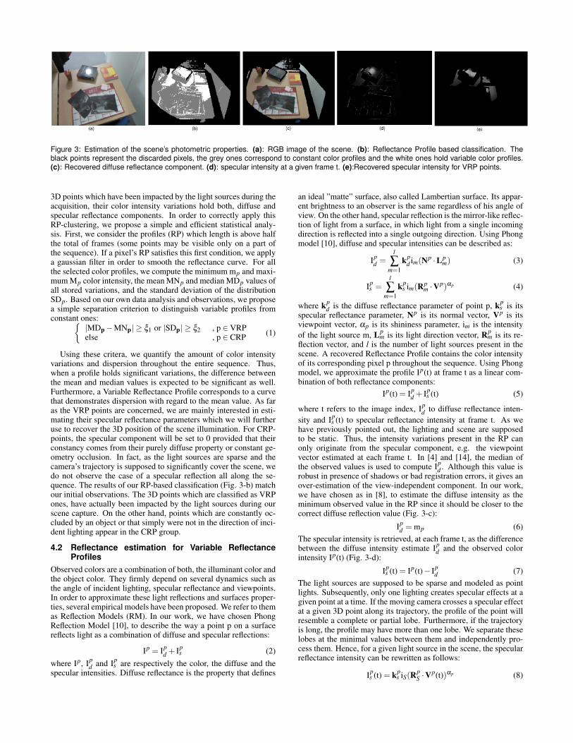
Figure 3: Estimation of the scene’s photometric properties. (a): RGB image of the scene. (b): Reflectance Profile based classification. Theblack points represent the discarded pixels, the grey ones correspond to constant color profiles and the white ones hold variable color profiles.(c): Recovered diffuse reflectance component. (d): specular intensity at a given frame t. (e):Recovered specular intensity for VRP points.
3D points which have been impacted by the light sources during theacquisition, their color intensity variations hold both, diffuse andspecular reflectance components. In order to correctly apply thisRP-clustering, we propose a simple and efficient statistical analy-sis. First, we consider the profiles (RP) which length is above halfthe total of frames (some points may be visible only on a part ofthe sequence). If a pixel’s RP satisfies this first condition, we applya gaussian filter in order to smooth the reflectance curve. For allthe selected color profiles, we compute the minimum mp and maxi-mum Mp color intensity, the mean MNp and median MDp values ofall stored variations, and the standard deviation of the distributionSDp. Based on our own data analysis and observations, we proposea simple separation criterion to distinguish variable profiles fromconstant ones:{
|MDp−MNp| ≥ ξ1 or |SDp| ≥ ξ2 , p ∈ VRPelse , p ∈ CRP (1)
Using these critera, we quantify the amount of color intensityvariations and dispersion throughout the entire sequence. Thus,when a profile holds significant variations, the difference betweenthe mean and median values is expected to be significant as well.Furthermore, a Variable Reflectance Profile corresponds to a curvethat demonstrates dispersion with regard to the mean value. As faras the VRP points are concerned, we are mainly interested in esti-mating their specular reflectance parameters which we will furtheruse to recover the 3D position of the scene illumination. For CRP-points, the specular component will be set to 0 provided that theirconstancy comes from their purely diffuse property or constant ge-ometry occlusion. In fact, as the light sources are sparse and thecamera’s trajectory is supposed to significantly cover the scene, wedo not observe the case of a specular reflection all along the se-quence. The results of our RP-based classification (Fig. 3-b) matchour initial observations. The 3D points which are classified as VRPones, have actually been impacted by the light sources during ourscene capture. On the other hand, points which are constantly oc-cluded by an object or that simply were not in the direction of inci-dent lighting appear in the CRP group.
4.2 Reflectance estimation for Variable ReflectanceProfiles
Observed colors are a combination of both, the illuminant color andthe object color. They firmly depend on several dynamics such asthe angle of incident lighting, specular reflectance and viewpoints.In order to approximate these light reflections and surfaces proper-ties, several empirical models have been proposed. We refer to themas Reflection Models (RM). In our work, we have chosen PhongReflection Model [10], to describe the way a point p on a surfacereflects light as a combination of diffuse and specular reflections:
Ip = Ipd + Ip
s (2)where Ip, Ip
d and Ips are respectively the color, the diffuse and the
specular intensities. Diffuse reflectance is the property that defines
an ideal ”matte” surface, also called Lambertian surface. Its appar-ent brightness to an observer is the same regardless of his angle ofview. On the other hand, specular reflection is the mirror-like reflec-tion of light from a surface, in which light from a single incomingdirection is reflected into a single outgoing direction. Using Phongmodel [10], diffuse and specular intensities can be described as:
Ipd =
l
∑m=1
kpd im(Np ·Lp
m) (3)
Ips =
l
∑m=1
kps im(Rp
m ·Vp)αp (4)
where kpd is the diffuse reflectance parameter of point p, kp
s is itsspecular reflectance parameter, Np is its normal vector, Vp is itsviewpoint vector, αp is its shininess parameter, im is the intensityof the light source m, Lp
m is its light direction vector, Rpm is its re-
flection vector, and l is the number of light sources present in thescene. A recovered Reflectance Profile contains the color intensityof its corresponding pixel p throughout the sequence. Using Phongmodel, we approximate the profile Ip(t) at frame t as a linear com-bination of both reflectance components:
Ip(t) = Ipd + Ip
s (t) (5)
where t refers to the image index, Ipd to diffuse reflectance inten-
sity and Ips (t) to specular reflectance intensity at frame t. As we
have previously pointed out, the lighting and scene are supposedto be static. Thus, the intensity variations present in the RP canonly originate from the specular component, e.g. the viewpointvector estimated at each frame t. In [4] and [14], the median ofthe observed values is used to compute Ip
d . Although this value isrobust in presence of shadows or bad registration errors, it gives anover-estimation of the view-independent component. In our work,we have chosen as in [8], to estimate the diffuse intensity as theminimum observed value in the RP since it should be closer to thecorrect diffuse reflection value (Fig. 3-c):
Ipd = mp (6)
The specular intensity is retrieved, at each frame t, as the differencebetween the diffuse intensity estimate Ip
d and the observed colorintensity Ip(t) (Fig. 3-d):
Ips (t) = Ip(t)− Ip
d (7)The light sources are supposed to be sparse and modeled as pointlights. Subsequently, only one lighting creates specular effects at agiven point at a time. If the moving camera crosses a specular effectat a given 3D point along its trajectory, the profile of the point willresemble a complete or partial lobe. Furthermore, if the trajectoryis long, the profile may have more than one lobe. We separate theselobes at the minimal values between them and independently pro-cess them. Hence, for a given light source in the scene, the specularreflectance intensity can be rewritten as follows:
Ips (t) = kp
s iS(RpS ·V
p(t))αp (8)

The unknown parameters are the combination of both, the specularparameter and the intensity of the light source S (kp
s iS), the reflec-tion vector Rp
S and the shininess coefficient αp. If the pixel’s inten-sity at the peak of the RP is not saturated, the product (kp
s iS) can beretrieved and is equal to the lobe’s peak intensity value. We referto the index of the frame where the maximum is reached as tm. Infact, when the specular effect occurs, the viewpoint vector and thereflection vector are initially supposed to be aligned. Subsequently,for every 3D point of the scene that holds a variable profile, wehave: {
kps iS = Ip
s (tm)Rp
S = Vp(tm)(9)
Estimated specular components can contain errors due to regis-tration misalignments. Hence, we apply a morphological erosionand recover the specular intensities kp
s iS and reflection vectors RpS
(Fig. 3-e). Since we have no guarantee that the profile has reachedits maximum possible value, we will be refining this estimation fur-ther in this work. The shininess parameter αp is proper to each ma-terial and is known to be larger for surfaces that are smoother andmore mirror-like: the larger αp , the narrower the RP lobe is. Weestimate αp using a non-linear Gauss-Newton optimization methodwith the following cost function:
αp = argminαp
N∑t=1
(Ips (t)−kp
s iS(RpS ·V
p(t))αp)2 (10)
where N is the number of total frames. As described in equation(10), we estimate the variable αp that minimizes the difference be-tween the observed specular intensities Ip
s (t) , and the intensitiesapproximated by Phong model throughout the entire sequence.
4.3 Light Source Position EstimationIn this section, we aim at estimating the 3D position of the lightsource responsible for specular effects int the scene. To begin with,we compute for each VRP-point p the light direction vector Lp
S us-ing the estimate of the reflection vector Rp
S :
LpS = 2.(Rp
S ·Np) ·Np−Rp
S (11)Using the Point Cloud Library (PCL), we proceed to surface normalestimation for every 3D point in the scene. The method estimatesthe normal of a plane tangent to the surface and uses a least-squareplane fitting solution. The problem of finding the 3D position of thelight source is similar to computing the intersection point of mul-tiple 3D lines. Hence, we estimate the position of the light sourceS= [xS,yS,zS]
T by using a least square method. Based on the roughestimation of the VRP specular components, we propose an itera-tive process to refine these estimates and improve the localizationof the light source. Using both the 3D coordinates P of the scenepoints and the 3D position of the light source S, we are able to up-date the light direction vector Lp
S and refine the reflection vector RpS
for all 3D points:
LpS =
S−P||S−P||
(12)
Finally, using a Gauss-Newton minimization method, we alter-natively refine the specular components and the lighting positionuntil they both converge:
(kps iS, αp) = argmin
(kps iS,αp)
N∑t=1
(Ips (t)−kp
s iS(RpS ·V
p(t))αp)2 (13)
RpS = argmin
RpS
N∑t=1
(Ips (t)−kp
s iS(RpS ·V
p(t))αp)2 (14)
In Fig. 4, the Euclidean distance between the estimated 3D posi-tion and the true (measured) position of the light source is equal to11cms for a mean distance of the light to the scene of 3.5 ms.
Figure 4: 3D position of the light source. The left image is a capturedpicture of scene and lighting. The right image describes the pointcloud of the scene (white pixels) and shows the estimated position ofthe light source (center of the yellow sphere).
4.4 Photometry-based classification of the sceneUnlike [8], we further consider 3D points which hold a constantspatio-temporal color profile, we have been referring to them asCRP points. These profiles contain exploitable information that al-low to recover their reflectance properties. In order to make the bestuse of these data, we first need to refine our RP-based classification.In section 4.1, we proposed a first classification within the entirecolor profiles dataset that separates Reflectance Profiles into VRPand CRP groups. Within the CRP class, we can encounter differentpoints with regard to their reflectance properties. Hence, they needto be processed differently in order to obtain accurate reflectanceestimates. Phong model [10] is rewritten as:
Ip(t) = Ipd +Op
S kps iS(R
pS ·V
p(t))αp (15)
where OpS is an occlusion parameter, equal to 1 if light source S is
visible from point p, and 0 otherwise. We added this parameter totake account of visibility within the scene. According to equation(15), a profile’s constancy is observed when the specular componentis equal to 0. This can be due to four possible reasons: the 3D pointis not visible from the specular light source S because an objectoccludes it (Op
S = 0). The 3D point belongs to a purely diffusesurface (kp
s = 0). The trajectory of the camera with respect to pointp and to the light source S is such that the reflection vector Rp
S andthe viewpoint vector Vp(t) have significantly different directions(Rp
S ·Vp(t) is always equal or close to 0). Last, the 3D point has a
constant specular effect all along the sequence, however as our lightsources are sparse and the camera trajectory is significantly varying,this case is not met. Based on these observations, we categorisethe CRP points into three main classes: Constantly Diffuse Points(CDP) such that (Rp
S ·Vp(t)) is equal or close to 0 all along the
sequence, Pure Diffuse Points (PDP) which are 3D points lit byall light sources and showing no specular reflection (Op
S = 1 andkp
s = 0). Constantly Occluded Points (COP) are 3D points whichare constantly occluded with respect to the estimated light source S(Op
S = 0). In the following, our objective is to fully classify CRP-points with regard to the previously defined subgroups (CDP, PDPand COP). Our classification is a two-pass procedure. The first passconsists in computing a visibility map. We have chosen the shadowmapping technique, a standard computer graphics algorithm. Werefer to the shadow map as Op
S where:{Op
S = 1 , p is a visible pointOp
S = 0 , p is an occluded point (16)
If point p is detected as an occluded point with regard to lightsource S, it is then classified as a COP point. Otherwise, it canbelong to either CDP or PDP subgroups. The second pass consistsin separating these two sub-classes by detecting 3D points whichmight be subject to a specular effect but still conserve a constant

profile, e.g. purely diffuse surfaces (PDP). To begin with, usingthe estimated reflection vector Rp
S (Section 4.2) and the viewpointvector Vp(t), we retrieve a novel profile ε
pS (t) such as:
εpS (t) = Rp
S ·Vp(t) (17)
We use a method similar to the one described in section 4.1 (Eq.1), with different thresholds, to distinguish variable and constantintensity profiles. If ε
pS (t) is significantly variable, then we conclude
that kps = 0 (e.g. the current point intensity shows a constant diffuse
value), point p belongs then to the PDP subgroup. If εpS (t) is a
constant intensity profile, the point belongs to the CDP subgroup.The different steps of the classification are reported in (Fig. 5). Theresults of our 3D classification are shown in (Fig. 6-a).
Figure 5: 3D-classification pipeline. It separates CRP-points to threemain classes: Constantly Diffuse Points (CDP) which are not ob-served under the impact of incident lighting. Pure Diffuse Points(PDP) which demonstrate a pure diffuse property (their specular in-tensity is equal to 0), and Constantly Occluded Points (COP) whichare constantly occluded by another surface/point with regard to thelight source.
Figure 6: (a): Photometry-based classification. White pixels are 3Dpoints with variable profiles, green pixels are diffuse points that be-long to the CDP subgroup and blue pixels are occluded points withregard to lighting (COP). (b): Recovered diffuse component for Con-stantly Occluded Points (COPs).
4.5 Diffuse reflectance estimation for Constant Re-flectance Profiles
In this section, our objective is to estimate surface diffuse re-flectance properties for all points with Constant Reflectance Pro-files (CRP). Our approach is based on cast shadows that are due toocclusion of identified light sources. These areas corresponding tothe COP points are described in the occlusion map. The method isbased on the comparison between points with the same diffuse re-flectance that differ through lighting: CRP-visible points (e.g. CDPand PDP) and CRP-occluded points (COP). The color intensity of
these points differs as follows:{Ip = Ip
d = Ipd,O + Ip
d,V , if p ∈ (CDP or PDP)Ip = Ip
d = Ipd,O , if p ∈ COP (18)
where Ipd,V corresponds to the diffuse color intensity due to
the light sources that are visible from CDP and PDP points only,and Ip
d,O corresponds to the diffuse color intensity due to the lightsources that are visible from all points. To begin with, we suppose-for now- that we are able to identify two points p1 and p2 withthe same unknown diffuse parameter (kp
d = kp1d = kp2
d ). Point p1 issupposed to belong to the CRP-visible subgroups whereas p2 be-longs to the COP subgroup. Since p1 and p2 are assumed to havethe same diffuse parameter, we can write:{
Ip1d = kp
d lpO +kp
d lp1V
Ip2d = kp
d lpO
(19)
where lp1V refers to the n light sources occluded from COP points
and lpO refers to light sources visible from both types of points:
lp1V = ∑
n(Np ·Lp
n)in (20)
lpO in both equations (19) is supposed to be same since the distance
between CRP-visible and COP points is considered to be smallwith regard to the distance of the light source. The n light sourcesin equation (20) are supposed to correspond to the ones identifiedthrough their specular effect. Hence, both kp
d and lpO can be esti-
mated for the selected points: kpd =
Ip1d −Ip2
dlp1V
lpO =
Ip2d
kpd
(21)
Except close to shadow edges, lighting is locally constant and thereis interest to consider a group of points as far as they are identifiedas having the same diffuse parameter kp
d :
kpd =
Ipd,V − Ip
d,O
lpV
(22)
where Ipd,V and lp
V correspond respectively to average diffuse com-ponent and visible light sources intensities computed over all pointsbelonging to the CRP-visible subgroups, and Ip
d,O is the average dif-fuse component intensity computed over all points belonging to theCOP group (e.g. constantly occluded points). lp
O is then estimatedas:
lpO =
∑p Ipd,COP
∑p kpd
(23)
Using the estimated kpd , we are able to recover the contribution of
the occluded light sources with regard to COP points (Fig. 6-b).
Diffuse-reflectance clusteringThe main challenge in estimating the parameter kp
d remains in iden-tifying visible and occluded surfaces corresponding to points withthe same unknown diffuse intensity. To achieve this goal, we pro-pose to group points with regard to several strong similarity met-rics: chromaticity values, color intensities, normal vectors and 3Dlocations. Chromaticity values are computed using the ModifiedSpecular Free (MSF) image that is more robust than Specular Freeimages [12]. In order to compute the average diffuse values Ip
d,V
and Ipd,O, we propose a feature-weighted filter defined as follows:
Ipd =
∑q(ωp,qIqd)
∑q ωp,q(24)

Figure 7: Augmented scenes, with different reflectance and illumination conditions. We demonstrate correctly rendered virtual objects as theyocclude real specular effects (note the presence of the recovered diffuse component in the occluded region) and show realistic shadows.
Ipd,V and Ip
d,O use a set of points q located respectively in visible andoccluded areas. These areas are known thanks to our photometry-based classification results. The weights ωp,q consider all the pre-viously mentioned similarity features:
ωp,q = e−∑ f cost( f ) (25)
where index f refers to a feature and cost(f) refers to the cost ofdissimilarity between features attached to points p and q.
4.6 Rendering
Using our estimates, we handle the way the color in the real sceneis modified by the presence of a virtual object while being un-der different reflections (diffuse and specular). This is achievedin a two-step procedure. First, using the estimated average dif-fuse components in both visible and occluded surfaces, we com-pute an attenuation coefficient β as the ratio of both recoveredvalues. The second step consists in detecting, with regard to ourphotometry-classification, the corresponding group/subgroup of thesurface points that the virtual object occludes (VRP, CDP, PDP orCOP). Hence, if the virtual object occludes a COP point, no shadowis rendered. On the contrary, if the virtual object occludes anothertype of point, we render the virtual shadow by multiplying its dif-fuse value by the attenuation factor β .
5 RESULTS
RGB-D sequences have been captured for eleven indoor staticscenes with differently shaped and textured objects under variousindoor lightings (e.g spot lights, led lights). In these scenes, weused salient control points with regard to our world frame in or-der to measure the accuracy of this method. In our experiments,an average error of 16cm (for an average distance of 3m to the lightsource) between the estimated position and true position of the lightsource is achieved, with a standard deviation of 3.8cm. In many in-door scenes, where the assumption of distant lighting may not hold,the recovery of the lighting’s 3D position has its importance to re-alistically render virtual objects.
5.1 AR Experiments
Figure 7 shows a variety of augmented scenes where virtual shad-ows and specular occlusions are correctly rendered. The most im-portant aspects of realism are the synthetic shadows (same attenua-tion as the corresponding real shadows) and the occlusion of spec-ularities by virtual objects to observe the recovered diffuse com-ponent. Our algorithm deals with textured surfaces and recoversconvincing diffuse maps for 3D real scenes where multiple objectswith different colors and shapes are present. Also, our proposedclassification (Sec. 4.4) allows us to remove shadows from our dif-fuse estimate. Subsequently, the latter can be used as a texture forour recovered 3D model. Further results and rendering comparisonsare shown in: https://youtu.be/CzxB2yA7kGw.
6 CONCLUSION
We presented a method for recovering a diffuse map of the scenefrom a sequence with specular reflections and cast shadows. Weestimated the reflectance parameters of the scene and recovered the3D position of light sources that create specular effects at the ob-served viewpoints. Specifically, in this paper we make use of thephotometric properties of a real scene to correctly insert virtual ob-jects for realistic Augmented Reality applications. Our method onlydeals with point light sources which produce hard shadows, anddoes not consider indirect illumination. For future work, we are in-terested in considering the soft shadow aspect that real surfaces canexhibit due to the presence of area lights. A clear step is then toextend our model and integrate it in our pipeline for more realisticindoor AR applications.
REFERENCES
[1] B. Boom, S. Orts-Escolano, X. Ning, S. McDonagh, P. Sandilands,and R. Fisher. Point light source estimation based on scenes recordedby a rgb-d camera. BMVC, 2013.
[2] A. Dame and E. Marchand. Second order optimization of mutual in-formation for real-time image registration. IEEE Trans. on Image Pro-cessing, 2012.
[3] S. Gibson, T. Howard, and R. Hubbold. Flexible image-based pho-tometric reconstruction using virtual light sources. In Eurographics,2001.
[4] J. Jachnik, R. A. Newcombe, and A. Davison. Real-time surface light-field capture for augmentation of planar specular surfaces. In ISMAR,2012.
[5] M. Knecht, G. Tanzmeister, C. Traxler, and M. Wimmer. Interactivebrdf estimation for mixed-reality applications. WSCG, 2012.
[6] K. Lee, Q. Zhao, X. Tong, M. Gong, S. Izadi, S. Lee, P. Tan, andS. Lin. Estimation of intrinsic image sequences from image+depthvideo. In ECCV, 2012.
[7] N. Neverova, D. Muselet, and A. Tremeau. Lighting estimation inindoor environments from low-quality images. In ECCV, 2012.
[8] K. Nishino, Z. Zhang, and K. Ikeuchi. Determining reflectance pa-rameters and illumination distribution from a sparse set of images forview-dependent image synthesis. In ICCV, 2001.
[9] D. Nowrouzezahrai, S. Geiger, K. Mitchell, R. Sumner, W. Jarosz,and M. Gross. Light factorization for mixed-frequency shadows inaugmented reality. In ISMAR, 2011.
[10] B. Phong. Illumination for computer generated pictures. Communica-tion of the ACM, 1975.
[11] I. Sato, Y. Sato, and K. Ikeuchi. Illumination distribution from bright-ness in shadows: Adaptive estimation of illumination distribution withunknown reflectance properties in shadow regions. In ICCV, 1999.
[12] H.-L. Shen and Q.-Y. Cai. Simple and efficient method for specularityremoval in an image. Applied optics, 2009.
[13] K. Torrance and E. Sparrow. Theory for off-specular reflection fromroughened surfaces. JOSA, 1967.
[14] D. Wood, D. Azuma, W. Aldinger, B. Curless, T. Duchamp,D. Salesin, and W. Stuetzle. Surface light fields for 3d photography.In SIGGRAPH, 2000.