lxcoscosimat.nl/wp-content/uploads/2014/05/7.0-lxcos-v1.0_en.pdf · voltage regulator products...
TRANSCRIPT

Voltage regulator for generators
FEB 2014 Instruction Manual
LXCOS V1.0
Generator rewinding & repair. Voltage regulator products Manual LXCOS V1.0_EN.doc
Version: 29-1-2014 15:33:00 Page 2 of 48
Electronics
Revision history
The table below provides a historical summary of the changes made to the LXCOS AVR. Revisions are listed in chronological order.
Product version 1.0.0 Change
Hardware version 1.0.0
First release. Software version 1.0.0
Manual version 1.0.0

Generator rewinding & repair. Voltage regulator products Manual LXCOS V1.0_EN.doc
Version: 29-1-2014 15:33:00 Page 3 of 48
Electronics
WARNINGS
The manual does not cover all technical details of the product. Specifications may be modified by the manufacturer without notice. For further information, the manufacturer should be contacted.
WARNING
The system should not be installed, operated, serviced or modified except by qualified personnel who understand the danger of electric shock hazards and have read and understood the user instructions
ELECTRICAL HAZARDOUS VOLTAGES DANGEROUS DO NOT OPERATE WHEN NOT FAMILIAR WITH GENERATORS
WARNING
Dangerous voltages are present at the voltage regulator board. Accidental contact with live conductors could result in serious electrical shock or electrocution. Disconnect the power source before making repairs, connecting test instruments, or removing or making connections to the voltage regulator or generator.
WARNING
Never work on a LIVE generator. Unless there is another person present who can switch off the power supply or stop the engine

Generator rewinding & repair. Voltage regulator products Manual LXCOS V1.0_EN.doc
Version: 29-1-2014 15:33:00 Page 4 of 48
Electronics
Table of contents Part 1/2
1. Introduction 1.0 General description 6 1.1 AVR dimensions 7 1.2 Absolute maximum ratings 8 1.3 Commissioning information 8
2. Installation 2.0 Interfaces overview 9 2.1 Adjustments overview 10 2.2 Terminals overview 11 2.3 Electrical characteristics 12
3. Operation and maintenance 3.0 AVR status 13 3.1 Modes of control 13 3.1.0 Idle 13 3.1.1 Buildup (PMG only) 14 3.1.2 Buildup (Self Excited) 14 3.1.3 Constant Voltage control 15 3.1.4 Volt per Hertz control 16
3.1.5 Current control 16
3.1.6 Power factor control 16
3.1.7 Error condition 16
3.2 Special Applications 17 3.2.0 Parallel operation 17
3.2.1 Parallel soft start 17
3.2.2 0-100% voltage control 18
3.2.3 0-100% current control 19 3.2.4 Options 19
4. Protections and diagnosis 4.0 LED error codes 20 4.1 Protections for Self Excited generators 20 4.2 Protections 21 4.2.0 Over voltage 21
4.2.1 Over current 22
4.2.2 Over excitation 23
4.2.3 AVR over temperature 24
4.2.4 Generator over temperature 25
4.2.5 Phase loss 26
4.2.6 Loss of excitation (only for PFC) 27
4.2.7 Loss of current sensing (only for PFC) 28

Generator rewinding & repair. Voltage regulator products Manual LXCOS V1.0_EN.doc
Version: 29-1-2014 15:33:00 Page 5 of 48
Electronics
Table of contents Part 2/2
5. Settings and adjustments
5.0 Generator voltage 29 5.1 Current limit 29 5.2 M-select (mode of operation) 30 5.3 Stability 30 5.4 Droop 31 5.5 Accessories range 31 5.6 Excitation ceiling 31 5.7 Cosphi 32 5.8 Selection Swithes 32 5.8.0 Voltage 32 5.8.1 Field Flash 32 5.9 Factory settings 33 5.10 Advanced settings 34 5.10.0 Flowchart adjusting advanced settings 34 5.10.1 Advaned settings table 36
6. Wiring diagrams 6.0 Wiring diagram LXCOS with aux windings 37 6.1 Wiring diagram LXCOS with PMG 38 6.2 Wiring diagram LXCOS self excite 39
7. CAN interface 7.0 CAN interface 42
Appendix A.1 General installation information 44 A.2 Contact 48

Generator rewinding & repair. Voltage regulator products Manual LXCOS V1.0_EN.doc
Version: 29-1-2014 15:33:00 Page 6 of 48
Electronics
1. INTRODUCTION
1.0 General description The LXCOS AVR is designed as a replacement for the Cosimat N+ AVR, incorporating at least the same standard functionality. The LXCOS AVR is a digitally operating AVR, providing optimal flexibility and configurability as is reflected by the additional capabilities of the LXCOS AVR. Nevertheless installation, maintenance and adjustment don’t require special application software. Additional features
Selectable mode of operation: Volt per Hertz control Constant voltage control Modes of control: Constant voltage control
Power factor control (PFC) 0-100% generator current control 0-100% generator voltage control Quadrature voltage droop for parallel operation Current limited motor start and volt per hertz control
Protections: Generator phase loss
AVR over temperature Generator over voltage Generator over current
Generator over temperature Loss of excitation during PFC
Loss of current sensing during PFC Flexible protections: User adjustable underspeed knee
User adjustable field over excitation User adjustable generator current limit
Communication: CAN bus AVR status LED
AVR status contact

Generator rewinding & repair. Voltage regulator products Manual LXCOS V1.0_EN.doc
Version: 29-1-2014 15:33:00 Page 7 of 48
Electronics
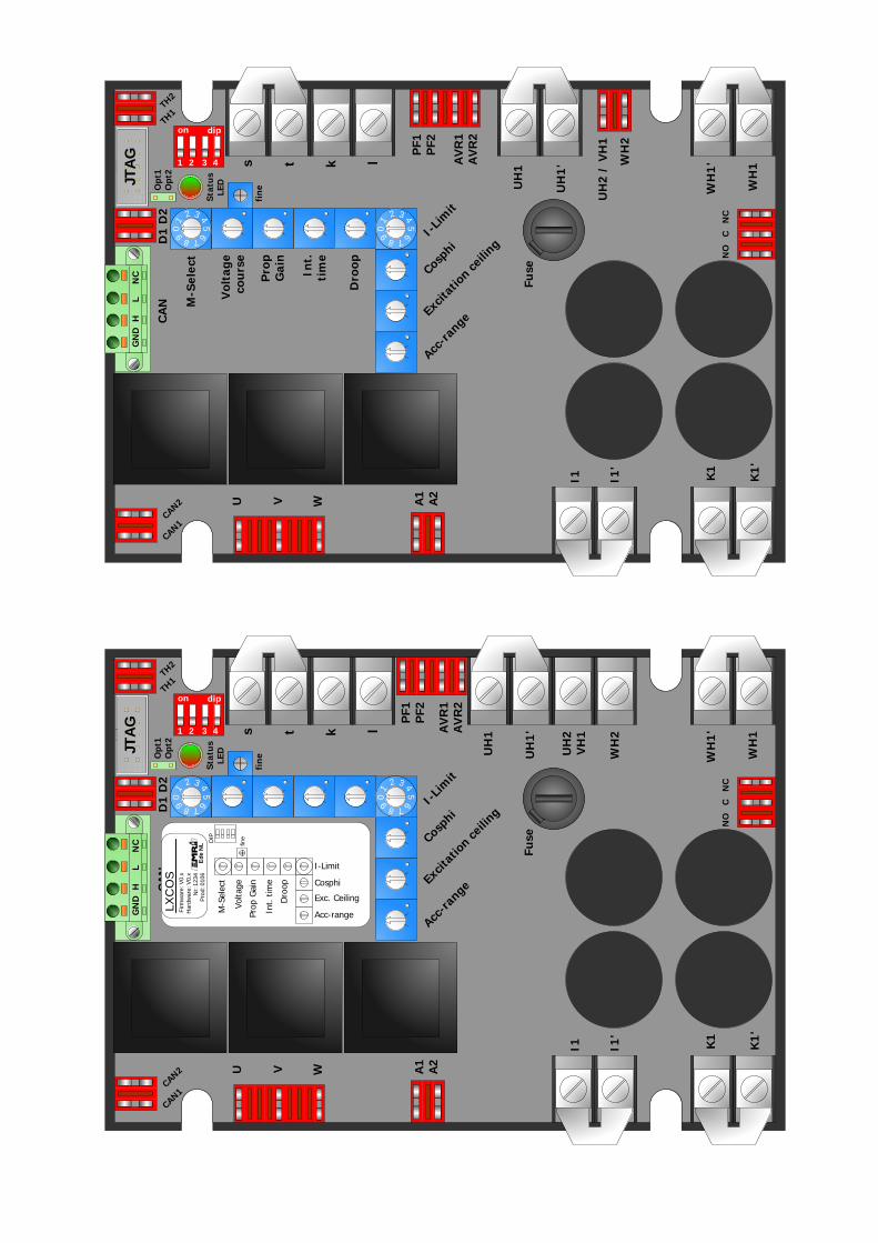
1.1 AVR dimensions The AVR LXCOS is size compatible to the original Cosimat N+ and therefore easy to exchange. The AVR is protected from the environment by a PUR coating. Prefabricated links are provided for CAN1-CAN2, TH1-TH2, S-T, AVR1-AVR2, UH1-UH1’, WH1–WH1’, I1–I1’ and K1 – K1’.
28
,5m
m
115,0mm
16
2,5
mm
14
0,5
mm
7,5
0m
m
0 1
3
4
2
56
78
9
0 1
3
4
2
56
78
9
on
dip
12
34
M-Select
Voltagecourse
PropGain
Int.time
Droop
K1'
WH1'
UH2VH1
WH2
PF1PF2
k
l
s
t
AVR1AVR2
NO C NC
A1A2
V
Acc-range
Excitation ceiling
Cosphi
I-Limit
fine
W
U
JTAG
D1 D2CAN
WH1
UH1'
UH1
Opt1Opt2
I1'
I1
K1
Fuse
StatusLED
CAN1
CAN2
TH1
TH2
GND H L NC
102,0mm
Fig 1. AVR dimensions
Measurements in mm
height ± 70mm

Generator rewinding & repair. Voltage regulator products Manual LXCOS V1.0_EN.doc
Version: 29-1-2014 15:33:00 Page 8 of 48
Electronics
1.2 Absolute maximum ratings
Symbol Parameter Condition Min. Max. Unit
U, V, W Voltage sensing input 480 V, < 30 s @ 50Hz - 520 VAC
I,K AVR field current < 10 s - 15* ADC
UH1-UH2 WH1-WH2 UH1-VH1-WH1
Supply input UH1-UH2, WH1-WH2, UH1-VH1-WH1 DC or 25 - 400 Hertz
15 15
240 135
VAC
VDC
UH1-UH2 Supply input self excitation DIP4 must be ON 6 - VAC
Rfield Field resistance @ 50 VAC supply
@ 150 VAC supply
5 15
- -
TAMB Operating temperature 95 % RHD non condensing -40 +70* °C
TSTG Storage temperature 95 % RHD non condensing -40 +70 °C
A1, A2 Accessories input ** -12 +12 VDC
k, l Droop, PFC, Limit CT 0,5A 2 VA, isolated CT < 30 s - 1,5 AAC
D1,D2 Analoge output 0 0
10 20
VDC
mADC
IC-NO, IC-NC Status contact switching current
UMAX 30VDC UMAX 230VAC
- -
5 5
ADC AAC
Table 1. Absolute maximum ratings * Always mount with heatsink fins aligned vertically and allow for sufficient airflow. ** Isolated.
1.3 Commissioning information The system should not be installed, operated, serviced or modified except by qualified personnel who understand the danger of electric shock hazards and have read and understood the user instructions. Defects in the generator or AVR may cause consequential loss. Precautions must be taken to prevent this from occurring. Never work on a LIVE generator. Unless there is another person present who can switch off the power supply or stop the prime mover. Dangerous voltages are present at the voltage regulator board. Accidental contact with live conductors could result in serious electrical shock or electrocution. Disconnect the power source before making repairs, connecting test instruments, or removing or making connections to the voltage regulator. The unit should be installed with respect to the environmental specifications as well as the rules mentioned in the General installation information. For safety reasons the voltage level potentiometers are best turned completely counter clockwise in order to start at the lowest possible voltage.

Generator rewinding & repair. Voltage regulator products Manual LXCOS V1.0_EN.doc
Version: 29-1-2014 15:33:00 Page 9 of 48
Electronics
2. INSTALLATION For a complete wiring diagram see Chapter 6.
2.0 Interfaces overview
Fig 2. Interfaces overview
Symbol Description Notes
Status LED AVR control mode & Error diagnostics See Table 6 and 8
CAN Interface CAN bus I/O
JTAG Interface Maintenance port Table 2. Interfaces

Generator rewinding & repair. Voltage regulator products Manual LXCOS V1.0_EN.doc
Version: 29-1-2014 15:33:00 Page 10 of 48
Electronics
2.1 Adjustments overview
Fig 3. Adjustments overview
Symbol Description Notes
Voltage coarse Course generator voltage setpoint See 5.8 for voltage range selection
Voltage fine Fine generator voltage setpoint See 5.8 for voltage range selection
I-Limit Generator current limit setting
M-Select AVR mode selection Also special control modes, see 5.2
Prop. Gain Proportional gain setpoint Stability adjustment
Int. time Integral time setpoint Stability adjustment
Droop Voltage droop setpoint For parallel operation
Acc-range Accessory input range adjustment A1+,A2-
Excitation ceiling Over excitation setpoint
Cosphi Cosphi setpoint Only enabled during parallel PFC
Dipswitches Voltage range and SE options See 5.8. Table 3. Adjustments

Generator rewinding & repair. Voltage regulator products Manual LXCOS V1.0_EN.doc
Version: 29-1-2014 15:33:00 Page 11 of 48
Electronics
2.2 Terminals overview
Fig 4. Terminals overview
Symbol Description Notes
U, V, W Voltage sensing input phase sequence U V W (Clockwise)
s, t External voltage adjust input
AVR1, AVR2 AVR On / Off input Off for ≥ 10s. resets previous AVR errors
UH1,UH2/VH1, WH1, WH2
Supply inputs
I1, K1 Field excitation output I1 = Field+, K1 = Field-
A1, A2 Accessory input (Isolated) Function dependent on M-select setting
k, l CT input for current sensing 0,5Aac input (or original AVK CT)
TH1, TH2 Thermistor sensing input Open for temperature error >2k Ohm
PF1, PF2 PFC on/offl input Closed for PFC
CAN1, CAN2 Can termination contact Can bus termination 120 Ohm when placed
OPT1,OPT2 Advanced options input See chapter 5.9.2 for all options
D1,D2 Optional analoge output 0-10Vdc / 0-20mAdc
NC, C, NO Status contact C-NO closed when AVR operational Table 4. Terminals

Generator rewinding & repair. Voltage regulator products Manual LXCOS V1.0_EN.doc
Version: 29-1-2014 15:33:00 Page 12 of 48
Electronics
2.3 Electrical characteristics Symbol Parameter Condition Min Max. Unit
U, V, W Voltage sensing input 50-60 Hz, Clockwise (CW) -
520 VAC
I1, K1 *** AVR field current @ TAMB ≤ 70ºC - 7* ADC
UH, UH2/VH,WH Supply input 30 - 400 Hertz 20 200 VAC
UH1-UH2 Supply input for self excitation
DIP3-DIP4 must be ON 5
-
VAC
Rfield Field resistance 15 -
TAMB Operating temperature 95 % RHD non condensing -40 +70* °C
TSTG Storage temperature 95 % RHD non condensing -40 +70 °C
Static control accuracy 1 %
A1, A2 Accessory input A1+, A2-**
Constant voltage control 0-100% Control
-10 0
+10 +10
V V
k, l Droop, PF CT, Limit CT Isolated CT, 0,01 - 0,5 AAC
S,T External Volt adjust Rs-t 250Ω Rs-t 500Ω
0 0 -
-10 -20 680
% % Ω
D1,D2 Analoge output D1+, D2-
0 0
10 20
VDC
mADC
Istatus Status contact switching current
UMAX 30VDC
UMAX 230VAC 3
3 ADC
AAC Table 5. Electrical characteristics
* Always mount with heatsink fins aligned vertically and allow for sufficient airflow. ** Isolated. *** See below for the safe operation area of the LXCOS voltage regulator.
Field forcing (<10s)Exciter
Field
Voltage
4.5V
0
210
Exciter Field Resistance
0.65Ω •∞Ω30Ω15Ω
9V
28V
2Ω
Safe operating area
Diagram 1. Operation area
Stresses above those listed under “Absolute Maximum Ratings” may cause permanent damage to the device. This is a stress rating only and functional operation of the device at those or any other conditions above those indicated in the operation listings of this specification is not implied. Exposure to maximum rating conditions for extended periods may affect device reliability and lifetime.

Generator rewinding & repair. Voltage regulator products Manual LXCOS V1.0_EN.doc
Version: 29-1-2014 15:33:00 Page 13 of 48
Electronics
3. Operation and maintenance
3.0 AVR Status The AVR’s status is indicated by the status LED. The options are depicted in table 6.
Voltage control
Current control/PF control
Buildup
Idle
LED Color / Blinks AVR status
Underspeed
Continuous green
Continuous orange
Orange blink
Green blink
Colour code
Continuous red
Error code Red/ green blink
Table 6. AVR status
3.1 Modes of control 3.1.0 Idle
When a supply is connected to the AVR and contact AVR1-AVR2 (AVR On/Off) is open, the AVR enters idle mode. During idle mode, field excitation is inhibited and protections are reset. The AVR will start from idle mode after resetting an error condition. When dipswitch 4 is on, the AVR will start field flashing. For more information about this option see 3.1.1 and 3.1.2

Generator rewinding & repair. Voltage regulator products Manual LXCOS V1.0_EN.doc
Version: 29-1-2014 15:33:00 Page 14 of 48
Electronics
3.1.1 Buildup (PMG only)
When contact AVR1-AVR2 (On/Off) is closed, the AVR enters build up mode. Protections are enabled and the generator voltage is ramped up to the nominal voltage. When the generator voltage is close to the nominal setpoint, the status contact is energized. Diagram 2 shows the sequence of events. Dipswitch 3 and 4 must be OFF, for PMG operation!
Generator
Voltage
400V
0V
390V
Idle Voltage build-up Stable
Time
Status
Contact (C-NO)
On
Off
Status
LED
On
Off
Diagram 2. Build up (PMG)
3.1.2 Buildup (Self Excited)
For self excitation (SE) mode, a link over AVR1-AVR2 must be placed and dipswitch 3 and 4 must be ON. After starting the generator, the AVR will field flash and enter build up mode. Protections are enabled and the generator voltage is ramped up to the nominal voltage. When the generator voltage is close to the nominal setpoint, the status contact is energized. Diagram 3 shows the sequence of events.
Generator
Voltage
400V
0V
390V
Generator starting Voltage build-up Stable
Time
Status
Contact (C-NO)
On
Off
Status
LED
On
Off
Field
flash
Diagram 3. Build up (SE)

Generator rewinding & repair. Voltage regulator products Manual LXCOS V1.0_EN.doc
Version: 29-1-2014 15:33:00 Page 15 of 48
Electronics
3.1.3 Constant Voltage control
The AVR starts constant voltage control after finishing the build up mode when this is selected with the M-Select switch (M-select mode 0, 1, 4, 5). The voltage/frequency characteristics are depicted in diagram 4. Below the underspeed frequency, the generator voltage is controlled according a Volt per Hertz slope. Both the underspeed knee frequency and the VPH slope are user adjustable. For a detailed description see table 10. When the generator frequency drops below 25 Hertz, the generator voltage is always controlled to a low level. In PMG-mode 15% of Unom (voltage selection) and in Self excitation-mode the mininimum SEsetpoint (See 5.10.1). An underspeed situation is visualized by a continuously red status LED.
U min
0V
400V
Underspeed
FrequencyGenerator Frequency
>25Hz
Status
LED
On
Off
VPH
Slope
Generator
Voltage
Diagram 4. Constant Voltage control

Generator rewinding & repair. Voltage regulator products Manual LXCOS V1.0_EN.doc
Version: 29-1-2014 15:33:00 Page 16 of 48
Electronics
3.1.4 Volt per Hertz control
The AVR performs Volt Per Hertz (VPH) control after finishing the build up mode when this is selected with the M-select switch (M-select mode 8, 9). The voltage/frequency characteristics are depicted in diagram 5. Note that the voltage is limited to a maximum of 500V irrespective of the generator frequency. When the generator frequency drops below 25 Hertz, the generator voltage is always controlled to a low level. In PMG-mode 15% of Unom (voltage selection) and in Self excitation-mode the minimum SE setpoint (See 5.10.1). An underspeed situation is visualized by a continuously red status LED.
Generator Frequency
Generator
Voltage
U min
0V
400V
>25Hz
480V
50Hz 60Hz
Status
LED
On
Off
VPH
Slope
Voltage
adjust
500V
Diagram 5. VPH control
3.1.5 Current control The AVR switches to current control when the generator current exceeds the generator current limit. The current limit is user selectable from 60% to 300% of the nominal generator current. To ensure sufficient supply voltage to the AVR during current limiting an external supply or PMG is usually required.
3.1.6 Power factor control The AVR performs Power Factor Control (PFC) when contact PF1-PF2 is closed. When the AVR is in Power factor control, both loss of excitation protection as well as the loss of current sensing protection are enabled. The power factor is user adjustable from 0.9 capacitive to 0.6 inductive. For more details about setting the power factor, see 5.7.
3.1.7 Error condition If an error condition triggers the AVR’s protections, field excitation is disabled and an error code is signaled by the status LED. See Chapter 4 (Error conditions) for a detailed description of the AVR ’s protections.

Generator rewinding & repair. Voltage regulator products Manual LXCOS V1.0_EN.doc
Version: 29-1-2014 15:33:00 Page 17 of 48
Electronics
3.2 Special Applications 3.2.0 Parallel operation
If the generator operates in parallel operation with one or more generators, reactive current sharing can be accomplished by means of Quadrature Droop Compensation (QDC). The amount of voltage droop must be precisely set equal for all generators under equal load conditions. The influence of the voltage droop on the generator voltage is depicted in diagram 6.
Generator Load
Generator
Voltage
0V
Unominal
Voltage droop
Inominal0A
more
capacitive
more
inductive
Diagram 6. Voltage droop If current limiting is enabled during parallel operation, all generators must have the same current limit and M-select (mode of control) settings. 3.2.1 Parallel soft start
When several AVR’s are used in parallel for a motor start application, all AVR’s must have the same current limit setting and M-select (mode of control) setting. To perform a synchronous start, it is required to make all AVR1-AVR2 (AVR On/Off) contacts simultaneously. To ensure sufficient supply voltage to the AVR during current limiting an external supply or PMG is usually required. Diagram 7 shows a sequence of events of a parallel soft start application.
Generator
Voltage
400V
0V
Current build-up Current Limiting Stable
Time
Status
Contact (C-NO)
On
Off
Status
LED
On
Off
Generator
Current Iload
0A
Ilimit
Voltage build-up
Diagram 7. Parallel soft start

Generator rewinding & repair. Voltage regulator products Manual LXCOS V1.0_EN.doc
Version: 29-1-2014 15:33:00 Page 18 of 48
Electronics
3.2.2 0-100% Voltage control
When M-select (mode of operation) is set to position 2 or 6, the generator voltage setpoint is controlled by an external supply source. The generator voltage setpoint is linear proportional with the voltage level supplied at terminals A1-A2. Terminal A1 is connected to the positive side of the external supply, terminal A2 connects to the negative supply side. The accessories range potentiometer may be used to adjust the generator’s voltage range as is depicted in diagram 8. If the Acc- range potentiometer is completely clockwise, 10Vdc input on A1-A2 corresponds with the generator voltage setpoint as set with the voltage potentiometers. If the Acc- range potentiometer is completely counter clockwise, influence on the generator voltage by A1-A2 is effectively disabled. To ensure sufficient supply voltage to the AVR during current limiting an external supply or PMG is usually required. During 0-100% voltage control, underspeed protection is disabled!. Note: DIP3 and DIP4 must be off.
A1-A2 Voltage
Generator
Voltage
200V
0V
400V
5V 10V
Acc- range 100%
Acc- range 50%
Acc- range 0%
0V
Diagram 8. Acc- range influence

Generator rewinding & repair. Voltage regulator products Manual LXCOS V1.0_EN.doc
Version: 29-1-2014 15:33:00 Page 19 of 48
Electronics
3.2.3 0-100% Current control
When M-select (mode of operation) is set to position 3 or 7, the generator current limit setpoint is controlled by an external supply source. The generator current limit setpoint is linear proportional with the voltage level supplied at terminals A1-A2. Terminal A1 is connected to the positive side of the external supply, terminal A2 connects to the negative supply side. The accessories range potentiometer may be used to adjust the generator’s current limit range as is depicted in diagram 9. If the Acc- range potentiometer is completely clockwise, 10Vdc input on A1-A2 corresponds with the generator current limit setpoint as set with the current limit potentiometer. If the Acc- range potentiometer is completely counter clockwise, influence on the generator current limit by A1-A2 is effectively disabled. To ensure sufficient supply voltage to the AVR during current limiting an external supply or PMG is usually required. Note: DIP3 and DIP4 must be off.
A1-A2 Voltage
Generator
Current
½ Ilimit
0A
Ilimit
5V 10V
Acc- range 100%
Acc- range 50%
Acc- range 0%
0V
Ilimit is set by pot. Current Limit
Diagram 9. Acc- range influence 3.2.4 Options
The LXCOS AVR can be functionally extended with the following options:
Type Description Interface
Droopkit Required for Droop, PFC, Current limit AVR terminals k-l
LX_VMA Required for voltage matching AVR terminals A1-A2
3F-Filter For filtering the generator sensing voltage. AVR terminals U-V-W Table 7. LXCOS options

Generator rewinding & repair. Voltage regulator products Manual LXCOS V1.0_EN.doc
Version: 29-1-2014 15:33:00 Page 20 of 48
Electronics
4. Protections and diagnosis
4.0 Led error codes If the AVR stops field excitation due to a fault condition, the fault that caused this is indicated by the status LED. Table 8 shows the relation between the number of red blinks and the error condition.
1
2
3
4
5
6
7
8
Overvoltage
Overcurrent
Excitation error
Overtemperature AVR
Overtemperature Gen
Phaseloss / Phase sequence error
Loss of excitation during PFC
Loss of current sensing during PFC
LED Color / Blinks Error condition
Table 8. Error codes The AVR may be reset from the error condition by opening contact AVR1-AVR2 (AVR On/Off) for at least 10 seconds. After a successful reset the AVR commences in idle mode and any information concerning the causing error is lost. In Self excitation-mode you must shut down the generator. If AVR is not working at all check fuse on AVR.
4.1 Protections for Self Excited generators When a protection is triggered and excitation is consequently stopped, this effectively also interrupts the AVR supply source for a Self Excited generator. Because the supply to the AVR is interrupted, the AVR is reset and will restart building up voltage again. If the cause of the error is still present this will cause a continuous tripping and restarting of the system.

Generator rewinding & repair. Voltage regulator products Manual LXCOS V1.0_EN.doc
Version: 29-1-2014 15:33:00 Page 21 of 48
Electronics
4.2 Protections
4.2.0 Over voltage The over voltage protection validates the generator voltage on terminals U,V and W. If the over voltage limit is exceeded for 1 second, the AVR switches off the status contact. See 5.8.0 for over voltage value. If the error condition still exists 1 second after opening the status contact, field excitation is stopped. In Self excitation-mode the AVR will shutdown and restart buildup, there for you must shut down the generator in case of an error. If the over voltage condition is relieved within 1 second after opening the status contact, the contact closes again and normal operation proceeds. An over voltage error is visualized by the status LED blinking red once. Removing the power supply by stopping the generator or opening the AVR On/Off contact at terminals AVR1-AVR2 for 10 seconds will reset the AVR.
Diagram 10 shows a sequence of events for diagnosis purposes in case of an over voltage error with a 400V Unom voltage range selection.
Generator
Voltage
400V
0V
520V
Time
Status
Contact(C-NO)
On
Off
Status
LED
On
Off<1s 1s 1s<1s 1s
Diagram 10. Over voltage

Generator rewinding & repair. Voltage regulator products Manual LXCOS V1.0_EN.doc
Version: 29-1-2014 15:33:00 Page 22 of 48
Electronics
4.2.1 Over current
The over current protection validates the generator current measured on terminals k and l. If the current limit, set by the user, is exceeded by 200% for 1 second, the AVR switches off the status contact. If the error condition still exists 1 second after opening the status contact, field excitation is stopped. In Self excitation-mode the AVR will shutdown and restart buildup, there for you must shut down the generator in case of an error. If the over current condition is relieved within 1 second after opening the status contact, the contact closes again and normal operation proceeds. An over current error is visualized by the status LED blinking red twice. Removing the power supply by stopping the generator or opening the AVR On/Off contact at terminals AVR1-AVR2 for 10 seconds will reset the AVR.
Diagram 11 shows a sequence of events for diagnosis purposes in case of an over current error.
Generator
Current (% of I-Limit)
100%
0V
200%
Time
Status
Contact (C-NO)
On
Off
Status
LED
On
Off<1s 1s 1s<1s 1s
Diagram 11. Over current

Generator rewinding & repair. Voltage regulator products Manual LXCOS V1.0_EN.doc
Version: 29-1-2014 15:33:00 Page 23 of 48
Electronics
4.2.2 Over excitation
The over excitation protection validates the generator field excitation measured on terminals I1 (+) and K1 (-). If the field excitation current exceeds the Excitation ceiling setpoint for more than 0,3 sec, the AVR switches off the status contact. The Excitation ceiling setpoint is user adjustable, from 1 Amps to 15 Amps, by means of the Excitation ceiling potentiometer. If the error condition still exists 10 seconds after opening the status contact, field excitation is stopped. In Self excitation-mode the AVR will shutdown and restart buildup, there for you must shut down the generator in case of an error. If the over excitation condition is relieved within 10 seconds after opening the status contact, the contact closes again and normal operation proceeds. An over excitation error is visualized by the status LED blinking red three times. Removing the power supply by stopping the generator or opening the AVR On/Off contact at terminals AVR1-AVR2 for 10 seconds will reset the AVR.
Diagram 12 shows a sequence of events for diagnosis purposes in case of an over excitation error.
Field
Excitation(A) 2A
0A
Excitation ceiling
Time
Status
Contact(C-NO)
On
Off
Status
LED
On
Off< 0,3 s > 0,3 s 10 s<10 s 0,3 s
Excitation ceiling is defined by excitation ceiling potentiometer
Diagram 12. Over excitation

Generator rewinding & repair. Voltage regulator products Manual LXCOS V1.0_EN.doc
Version: 29-1-2014 15:33:00 Page 24 of 48
Electronics
4.2.3 AVR over temperature
The AVR over temperature protection validates the AVR temperature, measured internally. If the over temperature limit of 85°C is exceeded for 10 seconds, the AVR switches off the status contact. If the error condition still exists 10 second after opening the status contact, field excitation is stopped. In Self excitation-mode the AVR will shutdown and restart buildup, there for you must shut down the generator in case of an error. If the AVR over temperature condition is relieved within 10 second after opening the status contact, the contact closes again and normal operation proceeds. An AVR over temperature error is visualized by the status LED blinking red four times. Removing the power supply by stopping the generator or opening the AVR On/Off contact at terminals AVR1-AVR2 for 10 seconds will reset the AVR.
Diagram 13 shows a sequence of events for diagnosis purposes in case of an AVR over temperature error.
Time
Status
Contact (C-NO)
On
Off
Status
LED
On
Off<10s 10s 10s<10s 10s
AVR
temperature (ºC)
50ºC
25º
C
85ºC
Diagram 13. AVR over temperature

Generator rewinding & repair. Voltage regulator products Manual LXCOS V1.0_EN.doc
Version: 29-1-2014 15:33:00 Page 25 of 48
Electronics
4.2.4 Generator over temperature
The generator over temperature protection validates the generator temperature, measured on terminals TH1-TH2. Either a clixon or thermistor may be connected, providing a high impedance signal (>2k Ohm) in case of temperature error. If no temperature protection is required, terminals TH1-TH2 must be shorted. If an over temperature error is detected for 10 seconds, the AVR switches off the status contact. If the error condition still exists 5 second after opening the status contact, field excitation is stopped. In Self excitation-mode the AVR will shutdown and restart buildup, there for you must shut down the generator in case of an error. If the generator over temperature condition is relieved within 5 second after opening the status contact, the contact closes again and normal operation proceeds. A generator over temperature error is visualized by the status LED blinking red five times. Removing the power supply by stopping the generator or opening the AVR On/Off contact at terminals AVR1-AVR2 for 10 seconds will reset the AVR.
Diagram 14 shows a sequence of events for diagnosis purposes in case of a generator over temperature error.
Time
Status
Contact (C-NO)
On
Off
Status
LED
On
Off<10s 10s 5s<5s 10s
TH1 – TH2
input
Closed
Open
Diagram 14. Generator over temperature

Generator rewinding & repair. Voltage regulator products Manual LXCOS V1.0_EN.doc
Version: 29-1-2014 15:33:00 Page 26 of 48
Electronics
4.2.5 Phase loss
The phase loss protection validates the presence of three generator phases on the terminals U, V and W. Upon missing of one or more phases for 300ms, the AVR switches off the status contact and decreases the voltage set point to a low level. phase loss is visualized by the red status LED. If the error condition still exists 5 second after opening the status contact, field excitation is stopped. In Self excitation-mode the AVR will shutdown and restart buildup, there for you must shut down the generator in case of an error. If the generator phase loss condition is relieved within 5 seconds after opening the status contact, the contact closes again and the voltage set point is ramped up again. A phase loss error is visualized by the status LED blinking red six times. Removing the power supply by stopping the generator or opening the AVR On/Off contact at terminals AVR1-AVR2 for 10 seconds will reset the AVR. Phase loss protection is disabled in current control and the generator voltage is below 10% of Unom (voltage selection). Diagram 15 shows a sequence of events for diagnosis purposes in case of a phase loss error.
AVR
reference
Voltage
400V
0V
U min
Generator
phase
U, V or W
400V
-400V
0V
Time
Status
Contact(C-NO)
On
Off
Status
Led
On
Off<0.3s 0.3s 5s0.3s
Diagram 15. Phaseloss

Generator rewinding & repair. Voltage regulator products Manual LXCOS V1.0_EN.doc
Version: 29-1-2014 15:33:00 Page 27 of 48
Electronics
4.2.6 Loss of excitation (only for PFC)
If the AVR is in Power factor control, by shorting the PF1-PF2 terminals, the loss of excitation protection is enabled. The loss of excitation protection validates the field excitation current on terminals I1 (+), K1 (-). If an excitation current lower than 250mA is detected for 5 seconds, the AVR switches off the status contact. This status signal can be used to disconnect the generator from the bus. If the error condition still exists 1 second after opening the status contact, field excitation is stopped. In Self excitation-mode the AVR will shutdown and restart buildup, there for you must shut down the generator in case of an error. If the loss of excitation condition is relieved within 1 second after opening the status contact, the contact closes again and normal operation proceeds. A loss of excitation error is visualized by the status LED blinking seven times. Removing the power supply by stopping the generator or opening the AVR On/Off contact at terminals AVR1-AVR2 for 10 seconds will reset the AVR.
Diagram 16 shows a sequence of events for diagnosis purposes in case of a loss of excitation error.
Field
Excitation(A)
0A
Time
Status
Contact (C-NO)
On
Off
Status
LED
On
Off<5s 5s 1s<1s 5s
0.25A
Diagram 16. Loss of excitation

Generator rewinding & repair. Voltage regulator products Manual LXCOS V1.0_EN.doc
Version: 29-1-2014 15:33:00 Page 28 of 48
Electronics
4.2.7 Loss of current sensing (only for PFC) If the AVR is in Power factor control, by shorting the PF1-PF2 terminals, the loss of current sensing protection is enabled. The loss of current sensing protection validates the generator current on terminals k, l. If a generator current lower than 1.5% of I nominal is detected for 5 seconds, the AVR switches off the status contact. This status signal can be used to disconnect the generator from the bus. If the error condition still exists 1 second after opening the status contact, field excitation is stopped. In Self excitation-mode the AVR will shutdown and restart buildup, there for you must shut down the generator in case of an error. If the loss of current sensing condition is relieved within 1 second after opening the status contact, the contact closes again and normal operation proceeds. A loss of current sensing error is visualized by the status LED blinking eight times. Removing the power supply by stopping the generator or opening the AVR On/Off contact at terminals AVR1-AVR2 for 10 seconds will reset the AVR.
Diagram 17 shows a sequence of events for diagnosis purposes in case of a loss of curent sensing error.
Time
Generator
Current(A)
0A
Status
Contact (C-NO)
On
Off
Status
LED
On
Off<5s 5s 1s<1s 5s
100%
1.5%
Diagram 17. Loss of current sensing

Generator rewinding & repair. Voltage regulator products Manual LXCOS V1.0_EN.doc
Version: 29-1-2014 15:33:00 Page 29 of 48
Electronics
5. Settings and adjustments 5.0 Generator Voltage The generator voltage setpoint is user adjustable by means of two voltage potentiometers. For range voltage setpoint See 5.8.0. The fine voltage potentiometer range is Unom ±1,5%. Turning the potentiometers clockwise increases the generator voltage, turning counter clockwise decreases the generator voltage.
5.1 Current Limit The generator current limit is adjustable by means of the I-limit switch. The switch positions and corresponding current limits are depicted in table 9. The current limit percentages are derived from the nominal generator current. The nominal generator current of 100% corresponds with a 0,5Aac current on terminals k – l. Please note that switch position 9 disables current limiting as well as the over current protection. Operation with current limit settings above the generator’s nominal current should always take place under continuous qualified supervision and within the limits set by the generator thermal damage curve.
Switch position Current Limit
0 60%
1 80%
2 100%
3 125%
4 150%
5 175%
6 200%
7 250%
8 300%
9 Unlimited Table 9. Current limit
Fig 6. Current Limit
Fig 5. Voltage adjustments

Generator rewinding & repair. Voltage regulator products Manual LXCOS V1.0_EN.doc
Version: 29-1-2014 15:33:00 Page 30 of 48
Electronics
5.2 M-select (mode of operation) The M-select (mode of operation) switch determines the AVR’s mode of operation and underspeed characteristics. The switch positions and corresponding modes are depicted in table 10. Ensure that the AVR’s is in idle mode before changing the M-select setting. For a more elaborate description of the control modes refer to Chapter 3.
Switch position
Description Control Mode A1-A2 range
Underspeed Frequency
Underspeed VPH slope *
0 Constant Voltage Control ±10Vdc 47 Hz 8 V/Hz
1 Constant Voltage Control ±10Vdc 47 Hz 16 V/Hz
2 0-100% Voltage Control with A1-A2 0-10Vdc - -
3 0-100% Current Control with A1-A2 0-10Vdc 47 Hz 8 V/Hz
4 Constant Voltage Control ±10Vdc 57 Hz 8 V/Hz
5 Constant Voltage Control ±10Vdc 57 Hz 16 V/Hz
6 0-100% Voltage Control with A1-A2 0-10Vdc - -
7 0-100% Current Control with A1-A2 0-10Vdc 57 Hz 8 V/Hz
8 Volt per Hertz Control ±10Vdc - 8 V/Hz
9 Volt per Hertz Control ±10Vdc - 8 V/Hz Table 10. M- select (mode of operation) * VPH slope by Unom is 400V.
5.3 Stability The generator stability and control response are adjustable by means of the proportional gain and integral time potentiometers. Turning the proportional gain potentiometer clockwise increases the proportional gain, turning counter clockwise decreases the proportional gain. Turning the integral time potentiometer clockwise increases the integral time, turning counter clockwise decreases the integral time. Turning the PI-controller must be performed by a control specialist to prevent damage to the AVR and generator.
Fig 7. M-select
Fig 8. Stability adjustments
Recovery time
time
Voltage
Int. Time
Prop. Gain
Overshoot
Fig 9. Stability behavior

Generator rewinding & repair. Voltage regulator products Manual LXCOS V1.0_EN.doc
Version: 29-1-2014 15:33:00 Page 31 of 48
Electronics
5.4 Droop When the generator is in parallel operation with one or more generators, Quadrature Droop Compensation is used to enable load sharing. The amount of voltage droop can be adjusted by means of the potentiometer. The droop potentiometer range is Unom - 5% @ cosphi 0,85 inductive. Turning the potentiometer clockwise increases the voltage droop, turning counter clockwise decreases the voltage droop. If the generator is not operating in parallel, turn the droop potentiometer completely counter clockwise to disable voltage droop. For a more detailed description of voltage droop see 3.2.0.
5.5 Accessories Range Terminals A1-A2 are used to connect external accessories that influence the AVR’s setpoint. The amount of influence can be adjusted by means of the Accessories range potentiometer. Terminals A1-A2 accept 0-10V or +/-10V, dependent on the mode of operation as is described in table 11. If the no external accessory is connected to terminals A1-A2, disable the input by turning the accessories range potentiometer completely counter clockwise. Setpoint is limited by voltage range maximum. See 5.8
Description Control Mode A1-A2 range
Accessories influence on setpoint
c.c.w. c.w.
Constant Voltage Control ±10Vdc 0% Unominal ±40% Unominal
0-100% Voltage Control with A1-A2 0-10Vdc 0% Unominal +100% Unominal
0-100% Current Control with A1-A2 0-10Vdc 0% Inominal +100% Inominal Table 11. Accessories influence
5.6 Excitation ceiling The excitation ceiling potentiometer is used to adjust the trip level of the over excitation protection. The excitation ceiling potentiometer range is linear, ranging from 1 to 15 Amps. Turning the potentiometer clockwise increases the excitation ceiling current setpoint, turning counter clockwise decreases the excitation ceiling current setpoint. Be aware that increasing the excitation ceiling above generator limits can cause permanent damage to the generators exciter field. For a more detailed description of the over excitation protection see 4.2.2.
Fig 10. Droop adjustment
Fig 11. Accessories adjustment
Fig 12. Excitation ceiling
Generator rewinding & repair. Voltage regulator products Manual LXCOS V1.0_EN.doc
Version: 29-1-2014 15:33:00 Page 32 of 48
Electronics
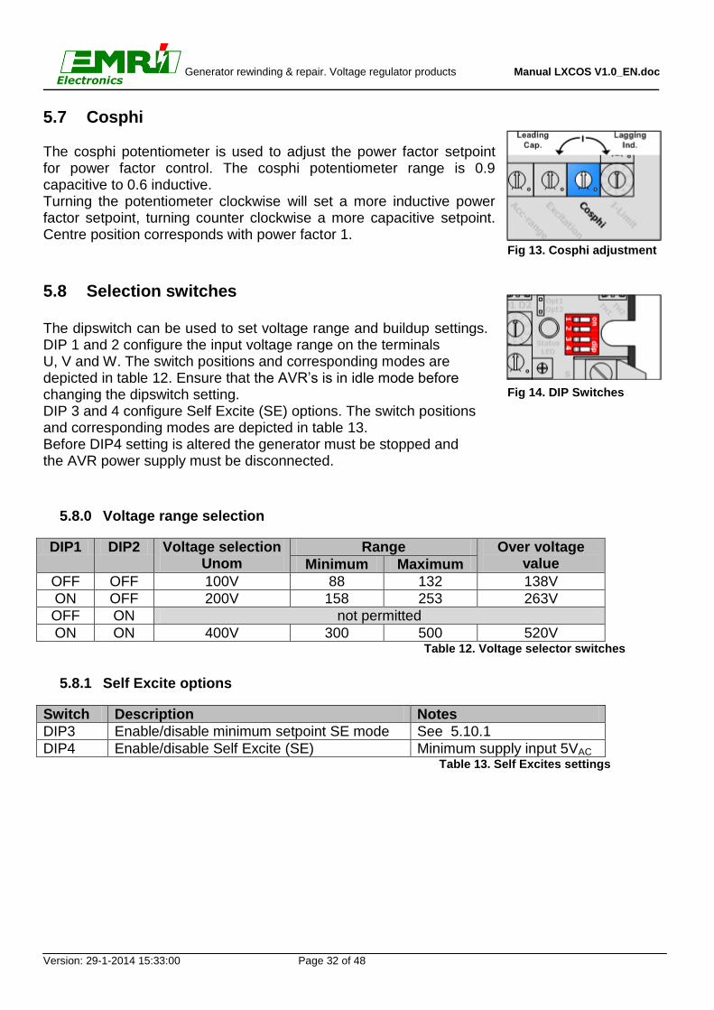
5.7 Cosphi The cosphi potentiometer is used to adjust the power factor setpoint for power factor control. The cosphi potentiometer range is 0.9 capacitive to 0.6 inductive. Turning the potentiometer clockwise will set a more inductive power factor setpoint, turning counter clockwise a more capacitive setpoint. Centre position corresponds with power factor 1.
5.8 Selection switches The dipswitch can be used to set voltage range and buildup settings. DIP 1 and 2 configure the input voltage range on the terminals U, V and W. The switch positions and corresponding modes are depicted in table 12. Ensure that the AVR’s is in idle mode before changing the dipswitch setting. DIP 3 and 4 configure Self Excite (SE) options. The switch positions and corresponding modes are depicted in table 13. Before DIP4 setting is altered the generator must be stopped and the AVR power supply must be disconnected.
5.8.0 Voltage range selection
DIP1 DIP2 Voltage selection Unom
Range Over voltage value Minimum Maximum
OFF OFF 100V 88 132 138V
ON OFF 200V 158 253 263V
OFF ON not permitted
ON ON 400V 300 500 520V Table 12. Voltage selector switches
5.8.1 Self Excite options
Switch Description Notes
DIP3 Enable/disable minimum setpoint SE mode See 5.10.1
DIP4 Enable/disable Self Excite (SE) Minimum supply input 5VAC Table 13. Self Excites settings
Fig 13. Cosphi adjustment
Fig 14. DIP Switches
Generator rewinding & repair. Voltage regulator products Manual LXCOS V1.0_EN.doc
Version: 29-1-2014 15:33:00 Page 33 of 48
Electronics
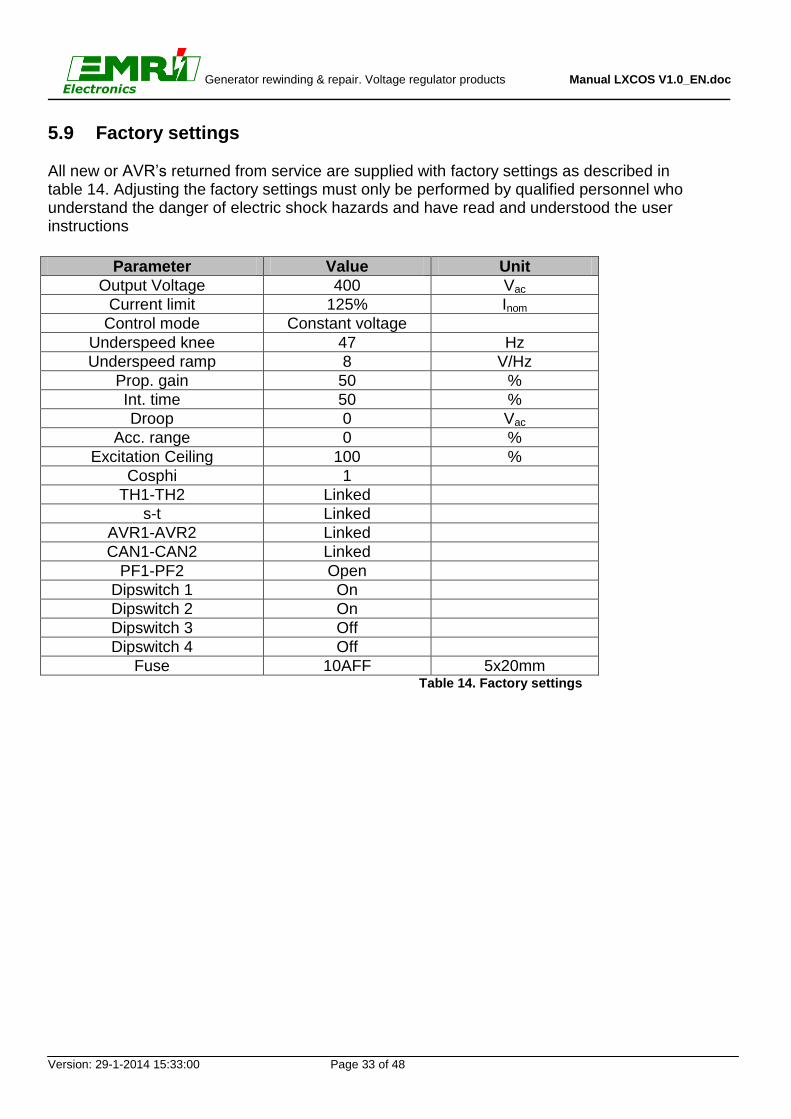
5.9 Factory settings All new or AVR’s returned from service are supplied with factory settings as described in table 14. Adjusting the factory settings must only be performed by qualified personnel who understand the danger of electric shock hazards and have read and understood the user instructions
Parameter Value Unit
Output Voltage 400 Vac
Current limit 125% Inom
Control mode Constant voltage
Underspeed knee 47 Hz
Underspeed ramp 8 V/Hz
Prop. gain 50 %
Int. time 50 %
Droop 0 Vac
Acc. range 0 %
Excitation Ceiling 100 %
Cosphi 1
TH1-TH2 Linked
s-t Linked
AVR1-AVR2 Linked
CAN1-CAN2 Linked
PF1-PF2 Open
Dipswitch 1 On
Dipswitch 2 On
Dipswitch 3 Off
Dipswitch 4 Off
Fuse 10AFF 5x20mm Table 14. Factory settings

Generator rewinding & repair. Voltage regulator products Manual LXCOS V1.0_EN.doc
Version: 29-1-2014 15:33:00 Page 34 of 48
Electronics
5.10 Advanced settings
The LXCOS features the option to change several advanced settings to optimize regulation. This chapter describes which settings can be adjusted and how to change those settings. The advanced settings are available for firmware version 1.0 and higher. Read this chapter carefully before changing any settings!
5.10.0 Flowchart adjusting advanced settings Advanced settings can be adjusted according the following flowchart.
Generator Shutdown?
Disconnect UH1, UH2/VH1,
WH1, WH2 wires from LX449.
Yes
With I-select, set the new value of
the variable.
Refer to figure 16 and table 15.
With M-select, select which
setting you want to change.
Refer to figure 15 and table 15.
Place jumper on option connector
as shown in figure 17.
Apply an external supply source to
UH1-WH1.
Not exceeding max. ratings!
Status LED flashing
Green - Off?
yes
Status LED flashing fast
Red - Off?
Setting is saved,
REMOVE JUMPER.
yesChange more settings?
Disconnect source and reconnect
UH1, UH2/VH1, WH1, WH2.
No
Open AVR1-AVR2,
DIP3 and DIP4 off.
yes
Close AVR1-AVR2,
Set DIP3 and DIP4 back
to previous position
Start
Finished
Set M-select and I-select
back to previous position.
Diagram 18. Flowchart advanced settings

Generator rewinding & repair. Voltage regulator products Manual LXCOS V1.0_EN.doc
Version: 29-1-2014 15:33:00 Page 35 of 48
Electronics
The M-select switch is used for selecting which setting to adjust. The I-limit switch is used for adjusting the selected setting.
Fig 15. M-select for variable select Fig 16. I-limit for variable changing
Place the programming jumper as shown on fig 17. Damage to the AVR can occur in case the jumper is misplaced
Fig 17. Jumper on option connector

Generator rewinding & repair. Voltage regulator products Manual LXCOS V1.0_EN.doc
Version: 29-1-2014 15:33:00 Page 36 of 48
Electronics
5.10.1 Advanced settings table
M-select I-limit
Pos. 1: Buildup gain
(MULT)
Pos. 2: Stability gain
(DIV)
Pos. 3: Min. setpoint,
SE mode.
Pos. 4: Protections
Pos. 5: Buildup time
@ startup
Pos. 6: Option output
Pos. 7: ACC input
modes
Pos. 8: Operation
modes
Pos. 0 0,1
(slowest) 1
(fastest) 0%
Excitation loss
disabled 1 sec.
Unused
Voltage Match
disabled
Inverted. output
disabled
Pos. 1 0,2 5 7,5% Excitation
loss enabled
3 sec. Voltage Match
enabled
Inverted output
enabled
Pos. 2 0,5 10 15% Phase loss
disabled 5 sec.
Cosphi setpoint disabled
Unused
Pos. 3 1 15 22,5% Phase loss
enabled 7 sec.
Cosphi setpoint enabled
Unused
Pos. 4 2 20 30% Current
loss disabled
10 sec. Unused Unused
Pos. 5 4 25 37,5% Current
loss enabled
20 sec. Unused Unused
Pos. 6 6 30 45% Unused 30 sec. Unused Unused
Pos. 7 8 35 52,5% Unused 45 sec. Unused Unused
Pos. 8 10 40 60% Unused 60 sec. Unused Unused
Pos. 9 14
(fastest) 45
(slowest) 67,5% Unused
Cosphi setpoint
0..255 sec. Unused Unused
Description
Extra multiplication factor for proportional gain. Only applied during field flash.
Extra division factor for proportional gain.
Initial setpoint from which the AVR’s ramps up after field flash. Setpoint in % of voltage range selection Unom
Enable or disable the desired protections.
The speed by which the AVR ramps from the minimum setpoint to the nominal setpoint.
Unused Enable or disable the desired modes of operation.
Enable of disable mode of operation
Table 15. Advanced settings
By setting both M-select and I-limit at 9 and by placing the programming header will reset the AVR to factory default settings. Default factory settings are highlighted in table 15.

Generator rewinding & repair. Voltage regulator products Manual LXCOS V1.0_EN.doc
Version: 29-1-2014 15:33:00 Page 37 of 48
Electronics
6. Wiring Diagrams

Generator rewinding & repair. Voltage regulator products Manual LXCOS V1.0_EN.doc
Version: 29-1-2014 15:33:00 Page 38 of 48
Electronics
6.0 Wiring diagram LXCOS with aux windings
01
3 42
56
789
01
3 42
56
789
on dip
1 2 3 4M
-Se
lect
Vo
lta
ge
co
urs
e
Pro
pG
ain
Int.
tim
e
Dro
op
K1
'
WH
1'
UH
2V
H1
WH
2
PF1
PF2
k ls t A
VR
1A
VR
2
NO
C
N
C
A1
A2
V
Acc-r
ange
Excita
tion
cei
ling
Cosphi
I-Li
mit
fin
e
WU
JT
AG
D1
D2
CA
N
WH
1
UH
1'
UH
1
Op
t1O
pt2
I1'
I1 K1
Fu
se
Sta
tus
LE
D
CAN1
CAN2
TH1
TH2
GN
D H
L
N
C
ExciterField
Stator Rotor
S1P1
+-
AUX winding
1
xxxV /
400V
l1 k1 l k s t U V W
WH
4
UH
4
UH
1R
UH
1R
UH
1R
UH
1
UH
1
24
UH
2
UH
2R
WH
1R
WH
1R
WH
1R
WH
1
14
WH
2R
WH
2R
WH
2
J1
R
J1
J1
J1
R
J1
K1
K1
R
Rvoltage
Sta
tus
Gnd
Tra
nsfo
rme
r is
ne
ed
ed
for
ge
ne
rato
r te
rmin
al
vo
lta
ge
s h
igh
er
tha
n4
00
V +
/-
10
% @
50
Hz
1
l1 k1 l k s t U V W
WH
4
UH
4
UH
1R
UH
1R
UH
1R
UH
1
UH
1
24
UH
2
UH
2R
WH
1R
WH
1R
WH
1R
WH
1
14
WH
2R
WH
2R
WH
2
J1
R
J1
J1
J1
R
J1
K1
K1
R
AVR
On
/ O
ff
kty/
ptc
-t°
Phas
e se
quen
ce:
U,V
,W
Bu
s
Ma
ins
Breaker
UV
WN

Generator rewinding & repair. Voltage regulator products Manual LXCOS V1.0_EN.doc
Version: 29-1-2014 15:33:00 Page 39 of 48
Electronics
6.1 Wiring diagram LXCOS with PMG
01
3 42
56
789
01
3 425
6
789
on dip
1 2 3 4M
-Se
lect
Vo
lta
ge
co
urs
e
Pro
pG
ain
Int.
tim
e
Dro
op
K1
'
WH
1'
UH
2V
H1
WH
2
PF1
PF2
k ls t A
VR
1A
VR
2
NO
C
N
C
A1
A2
V
Acc-r
ange
Excita
tion
cei
ling
Cosphi
I-Li
mit
fin
e
WU
JT
AG
D1
D2
CA
N
WH
1
UH
1'
UH
1
Op
t1O
pt2
I1'
I1 K1
Fu
se
Sta
tus
LE
D
CAN1
CAN2
TH1
TH2
GN
D
H
L
NC
ExciterField
Stator Rotor
S1P1
+-
1
xxxV /
400V
kty/
ptc
-t°
l1 k1 l k s t U V W
WH
4
UH
4
UH
1R
UH
1R
UH
1R
UH
1
UH
1
24
UH
2
UH
2R
WH
1R
WH
1R
WH
1R
WH
1
14
WH
2R
WH
2R
WH
2
J1
R
J1
J1
J1
R
J1
K1
K1
R
Rvoltage
Sta
tus
Gnd
Tra
nsfo
rme
r is
ne
ed
ed
for
ge
ne
rato
r te
rmin
al
vo
lta
ge
s h
igh
er
tha
n4
00
V +
/-
10
% @
50
Hz
1
l1 k1 l k s t U V W
WH
4
UH
4
UH
1R
UH
1R
UH
1R
UH
1
UH
1
24
UH
2
UH
2R
WH
1R
WH
1R
WH
1R
WH
1
14
WH
2R
WH
2R
WH
2
J1
R
J1
J1
J1
R
J1
K1
K1
R
PMG
AVR
On
/ Off
Phas
e se
quen
ce:
U,V
,W
Bu
s
Ma
ins
Breaker
UV
WN

Generator rewinding & repair. Voltage regulator products Manual LXCOS V1.0_EN.doc
Version: 29-1-2014 15:33:00 Page 40 of 48
Electronics
6.2 Wiring diagram LXCOS self excite
01
3 42
56
789
01
3 425
6
789
on dip
1 2 3 4
M-S
ele
ct
Vo
lta
ge
co
urs
e
Pro
pG
ain
Int.
tim
e
Dro
op
K1
'
WH
1'
UH
2V
H1
WH
2
PF1
PF2
k ls t A
VR
1A
VR
2
NO
C
N
C
A1
A2
V
Acc-r
ange
Excita
tion
cei
ling
Cosphi
I-Li
mit
fin
e
WU
JT
AG
D1
D2
CA
N
WH
1
UH
1'
UH
1
Op
t1O
pt2
I1'
I1 K1
Fu
se
Sta
tus
LE
D
CAN1
CAN2
TH1
TH2
GN
D H
L
N
C
Phas
e se
quen
ce:
U,V
,W
ExciterField
Stator Rotor
S1P1
+-
1xxxV /
400V
kty/
ptc
-t°
l1 k1 l k s t U V W
WH
4
UH
4
UH
1R
UH
1R
UH
1R
UH
1
UH
1
24
UH
2
UH
2R
WH
1R
WH
1R
WH
1R
WH
1
14
WH
2R
WH
2R
WH
2
J1
R
J1
J1
J1
R
J1
K1
K1
R
Rvoltage
Sta
tus
Gnd
Tra
nsfo
rme
r is
ne
ed
ed
for
ge
ne
rato
r te
rmin
al
vo
lta
ge
s h
igh
er
tha
n4
00
V +
/-
10
% @
50
Hz
1
l1 k1 l k s t U V W
WH
4
UH
4
UH
1R
UH
1R
UH
1R
UH
1
UH
1
24
UH
2
UH
2R
WH
1R
WH
1R
WH
1R
WH
1
14
WH
2R
WH
2R
WH
2
J1
R
J1
J1
J1
R
J1
K1
K1
R
xxxV /
115V
1000VA
AVR
On
/ Off
Bu
s
Ma
ins
Breaker
UV
WN

Generator rewinding & repair. Voltage regulator products Manual LXCOS V1.0_EN.doc
Version: 29-1-2014 15:33:00 Page 41 of 48
Electronics

Generator rewinding & repair. Voltage regulator products Manual LXCOS V1.0_EN.doc
Version: 29-1-2014 15:33:00 Page 42 of 48
Electronics
7. CAN Interface For external monitoring of the LXCOS EMRI give you the possibility to read out several values by a serial CAN interface.
0 1
3
4
2
56
78
9
0 1
3
4
2
56
78
9
on
dip
12
34
M-Select
Voltagecourse
PropGain
Int.time
Droop
K1'
WH1'
UH2VH1
WH2
PF1PF2
k
l
s
t
AVR1AVR2
NO C NC
A1A2
V
Acc-range
Excitation ceiling
Cosphi
I-Limit
fine
W
U
JTAG
D1 D2CAN
WH1
UH1'
UH1
Opt1Opt2
I1'
I1
K1
Fuse
StatusLED
CAN1
CAN2
TH1
TH2
GND H L NC
Ex
cite
rFie
ldS
tato
rR
oto
r
S1P1
+-
AU
X w
ind
ing
1
xxxV / 400V
l1
k1
l
k
s
t
U
V
W
WH4
UH4
UH1R
UH1R
UH1R
UH1
UH1
24
UH2
UH2R
WH1R
WH1R
WH1R
WH1
14
WH2R
WH2R
WH2
J1R
J1
J1
J1R
J1
K1
K1R
Rvoltage
Status
Gnd
Transformer is neededfor generator terminalvoltages higher than400V +/- 10% @ 50Hz
1
l1
k1
l
k
s
t
U
V
W
WH4
UH4
UH1R
UH1R
UH1R
UH1
UH1
24
UH2
UH2R
WH1R
WH1R
WH1R
WH1
14
WH2R
WH2R
WH2
J1R
J1
J1
J1R
J1
K1
K1R
AVR On/ Off
kty/ptc -t°
Phase sequence:U,V,W
Bus
Mains
Bre
ak
er
U V W N
Serial-USB
ConverterUSB
12
Va
c P
ow
er
RS
23
2
CAN
Mains Power
230Vac
For more information about this option please contact EMRI.
Fig 18. CAN interface

Generator rewinding & repair. Voltage regulator products Manual LXCOS V1.0_EN.doc
Version: 29-1-2014 15:33:00 Page 43 of 48
Electronics
Appendix

Generator rewinding & repair. Voltage regulator products Manual LXCOS V1.0_EN.doc
Version: 29-1-2014 15:33:00 Page 44 of 48
Electronics
A.1 General installation information Absolute Maximum Ratings
- The Absolute Maximum Ratings are those limits for the device that, if exceeded, will likely damage the device. Exceeding the absolute maximum ratings voids any warranty and/or guarantee.
Mounting
- Mounting of the product should be done in such a way that the absolute maximum ambient temperature rating of the product will never be exceeded.
- Mounting of the product should be done in such a way that maximum cooling (direction of cooling ribs and direction of airflow) is achieved.
- Mounting of the product should be done in such a way that no humid air can flow through the product or condensation occurs.
- Mounting of the product should be done in such a way that dust or other materials or residue will not remain in or on the product.
- Mounting of the product should be done in such a way that the maximum vibration is not exceeded.
- Mounting of the product should be done in such a way that personal contact with persons is impossible.
Wiring
- Diameter size of the wiring should be enough to carry the expected current. Wire insulation should be enough to withstand the expected operating voltages and temperatures.
- To improve EMC emission and immunity, care should be taken for the lay out of the wiring. This in respect to all wiring in the installation.
- Keep current carrying wires as short as possible. - Keep wires carrying a total sum of zero Ampere close to each other, or in one single
cable. E.g. U, V, W or I1 (+) and K1 (-), or Phase and neutral, s and t. - Avoid current carrying conductors next to sensing or control wiring. Especially current
controlled by SCR’s or PWM controlled transistors. - If sensitive sensing signal cables need to be laid across distance along other cabling,
shielded cable is preferred. Keep the shield as long as possible and the wiring outside the shield as short as possible. Do not solder or shrink the shield to a regular wire. Connect the original shield to ground at one side with an as large as possible contact surface.

Generator rewinding & repair. Voltage regulator products Manual LXCOS V1.0_EN.doc
Version: 29-1-2014 15:33:00 Page 45 of 48
Electronics
Additional installation information
- When the product is supplied by means of a transformer, it should never be an auto-transformer. Auto-transformers react as voltage sweep up coil and may cause high voltage peaks.
- Standard fit capacitors or over-voltage suppressers across I1 (+) and K1 (-), or exciter field terminals inside the generator should be removed.
- When the product is supplied by means of a transformer, it should be able to carry at least the maximum expected current. Advisable is, to have a transformer which can carry twice the maximum expected current. Inductive loads make voltage sacks and peeks into the secondary voltage of a transformer, from which the device may malfunction.
- It is not recommended to apply switches in dc outputs. It is preferred to use switches in the ac supply inputs of devices. In case it is unavoidable to have switches in the dc output of a device, action must be taken to avoid over voltage damage to the device due to contact arcing. Use a voltage suppressor across the output.
- It is not recommended to apply switches or fuses in the sensing lines. Defects can cause high voltage situations due to over-excitation.
- When using a step down transformer in medium or high voltage generators, the transformer should be three phase (if three phase sensing), and the transformer should be suitable for acting as a sensing transformer. If the transformer is unloaded, connect a resistor to avoid voltage waveform distortion.
- The phase relation from the generator to the AVR is important. Also when voltage transformers and/ or current transformers are installed.
- When using a step down or insulation transformer in the droop circuit, phase relation from the generator to the AVR is important.
- CT’s wiring, connected to the AVR should never be grounded. - Always disconnect electronic products, circuits and people before checking the
insulation resistance (Megger check). - Due to differences in generators impedance’s, EMC behavior is not predictable.
Therefore the commissioner / installer should be aware of proper and correct installation.
- Large, highly inductive, exciter stator windings can cause destructive high voltage peaks. Adding a resistor from 10 to 20 times the exciter stator field resistance reduces voltage spikes. If necessary filter can be fitted additionally. (e.g. snubber, RC-network)
- Upon problems during commissioning, faulty behavior or defects in the generator, consult the fault finding manual at our web site
- Some advises may be overdone or seem extraordinary, but since the electrical rules are the same everywhere, these advises are given.

Generator rewinding & repair. Voltage regulator products Manual LXCOS V1.0_EN.doc
Version: 29-1-2014 15:33:00 Page 46 of 48
Electronics
Empty page

Generator rewinding & repair. Voltage regulator products Manual LXCOS V1.0_EN.doc
Version: 29-1-2014 15:33:00 Page 47 of 48
Electronics
Empty page

Generator rewinding & repair. Voltage regulator products Manual LXCOS V1.0_EN.doc
Version: 29-1-2014 15:33:00 Page 48 of 48
Electronics
A.2 Contact
See our website www.emri.nl for local suppliers
Rafeining ehf Hafnarfjordur - Iceland Tel: +354 565 3049 Fax: +354 565 3048 E-mail: [email protected] Internet: www.rafeining.is
Frydenbø Electric A/S Bergen - Norway Tel: + 47 55 34 91 00 Fax: + 47 55 34 91 10 E-mail: [email protected] Internet: www.frydenbo.no
Myren & Co. AB Askim - Sweden Tel: +46 317481860 Fax: +46 317481870 E-mail: [email protected] Internet: www.myren.com
Yneldo Electronics Roodepoort - South Africa Tel: +27(0)117637053 Fax: +27(0)117634212 E-mail: [email protected] Internet: www.yneldo.com
KDU Technical Services Sharjah - United Arab Emirates Tel: +971-6-5575480 Fax: +971-6-5575490 E-mail: [email protected] Internet: www.kdutech.ae
Cyclect Electrical Engineering Singapore Tel: +65 6868 6013 Fax: +65 6863 6260 E-mail: [email protected] Internet: www.cyclect.com.sg
Marel Serwis Szczezin-Mierzyn - Poland Tel: +48 91 48 58 388 Fax: +48 91 48 79 948 E-mail: [email protected] Internet: www.marel.szczecin.pl
An-Elec Sp. z o.o. Gdynia - Poland Tel: +48 58 668 44 00 Fax: +48 58 668 44 66 E-mail: [email protected] Internet: http://an-elec.pl
MJR Controls Stockton on Tees - United Kingdom Tel: +44 1642 762 151 Fax: +44 1642 762 502 Email: [email protected] Internet: www.mjrcontrols.com
Stavros Kassidiaris S.A. Piraeus - Greece Tel: +30 210 4636000 Fax: +30 210 4624471 E-mail: [email protected] Internet: www.kassidiaris.gr
Manufacturer: EMRI Electronics B.V. Morsestraat 10 6716 AH, Ede, Netherlands Tel: (+31) 0318 620427 Fax: (+31) 0318 634615 Website: www.emri.nl E-mail: [email protected]
Electricidad Juan Betancor S.L. Las Palmas – Canary Islands Tel: +34 928327054 Fax: +34 928327055 Email:[email protected]
North Star USA inc. Fort Lauderdale, Florida Tel: +1 800 571-4453 Fax: +1 3052985727 Email:[email protected]
Elektrisk Drivteknik EDT AB Kungälv, Sweden Tel: +46-705-28 20 60 Tel: +46-709-50 47 90 Website: www.edtab.se Email:[email protected]
Ramtec Marine Systems LLC Kemah, Texas Tel: +1-281-334-2904 Fax::+1-832-221-5642 Website: www.ramtec-marine.com Email: [email protected]
01
3 42
56789
01
3 42
56789
on dip
1 2 3 4
M-S
elec
t
Vol
tage
co
urse
Pro
p G
ain
Int.
ti
me
Dro
op
K1'
WH
1'
UH
2V
H1
WH
2
PF1
PF2
k ls t AV
R1
AV
R2
NO
C
N
C
A1
A2V
Acc-ra
ngeExcit
atio
n ceilin
g
Cosphi
I-Lim
it
fine
WU
JTA
G
D1
D2
CA
N
WH
1
UH
1'
UH
1
Opt
1O
pt2
I1'
I1 K1
Fuse
Stat
usLE
D
CAN1CAN2
TH1
TH2
GN
D H
L
N
C
LXC
OS
Firm
war
e: V
0.x
Nr:
1234
Har
dwar
e: V
0.x
Prod
: 010
6Ed
e N
L
M-S
elec
t
Volta
ge
Prop
Gai
n
Int.
tim
e
Dro
op
Acc-range
Exc. Ceiling
Cosphi
I-Limit
fineDIP
01
3 42
56789
01
3 42
56789
on dip
1 2 3 4
M-S
elec
t
Vol
tage
co
urs
e
Pro
p G
ain
Int.
ti
me
Dro
op
K1'
WH
1' k ls t
NO
C
N
C
A1
A2V
Acc-ra
ngeExcit
atio
n ceili
ng
Cosphi
I-Lim
it
fine
WU
JTA
G
D1
D2
CA
N
WH
1
Opt
1O
pt2
I1'
I1 K1
Fuse
Stat
usLE
D
CAN1CAN2
TH1
TH2
GN
D H
L
N
C
UH
2 /
VH
1
WH
2
PF1
PF2
AV
R1
AV
R2
UH
1'
UH
1

AvK
DSG
86-
125_
Low
Vol
tage
Gen
erat
or L
X_C
OS
P.Lo
dder
Jan
2014
V1.0
ENG
DA
TE
VER
SIO
N
2P
AG
E
AvK_
DS
G_D
IG_L
X_C
OS
defin
itief
aan
gepa
st.v
sd
CAN1CAN2
TH1
TH2
l1 k1 l k s t U V W
UH
1RU
H1R
UH
1RU
H1
UH
124 UH
2U
H2R
WH
1RW
H1R
WH
114
WH
2RW
H2R
J1 J1R
J1R
K1R K1J1J1WH
4U
H4
WH
1R
WH
2
X1
U1
V1
W1
NE
G1
G3
G2
UH
1
WH
1
F1
11L
21L
12(i)
22(i)
12(k
)
22(k
)
L K
l k
T6
U V W
R1
X2
13,1
4-Q
PF
bei l
inke
m D
rehf
eld
“U” u
nd “W
” tau
sche
nex
chan
ge “U
” and
“W”
at a
nti-c
lock
wis
e ro
tatin
g fie
ld
Sch
altb
ild fü
r DS
G-G
ener
ator
en (a
b D
SG
86…
)m
it H
ilfsw
ickl
ung
Con
nect
ion
diag
ram
m fo
r DS
G-g
ener
ator
s(D
SG
86…
) with
aux
iliary
win
ding
s

AvK
DS
G 5
2-74
Low
Vol
tage
Gen
erat
or L
X_C
OS
P.Lo
dder
Jan
2014
V1.0
ENG
DA
TE
VER
SIO
N
3P
AG
E
AvK_
DS
G_D
IG_L
X_C
OS
defin
itief
aan
gepa
st.v
sd
CAN1CAN2
TH1
TH2
X1
U1
V1
W1
NE
T6
G1
G3
G2
R1
L K
l k
UH
1
WH
1
F1
11L
21L
12(i)
22(i)
12(k
)
22(k
)

AvK
DIG
HV
LX
_CO
S
P.L
odde
r
Jan
2014
V1.
0
EN
G
DA
TE
VER
SIO
N
4PA
GE
AvK
_DSG
_DIG
_LX_
CO
S d
efin
itief
aan
gepa
st.v
sd
CAN1CAN2
TH1
TH2
X2
+ -~
~V2
G2
G3
X1U
1V1
W1
E
T6L K
l kT2
4 N
X1U
2W
2V2
U V W
l1 k1 l k s t U V W 32 31 23U
H1R
UH
1RU
H1R
UH
1U
H1
24 UH
2U
H2R
UH
2RU
H3
UH
313
WH
1RW
H1R
WH
114
WH
2RW
H2
J2 J2 K2
K2 J1 J1R
J1R
K1R K1
J1J1
R1
13,1
4-Q
PF

AvK
DIG
MV
LX
_CO
S
P.L
odde
r
Jan
2014
V1.
0
EN
G
DAT
E
VER
SIO
N
5P
AGE
AvK
_DSG
_DIG
_LX
_CO
S de
finiti
ef a
ange
past
.vsd
CAN1CAN2
TH1
TH2
l1 k1 l k s t U V W
UH
1RU
H1R
UH
1RU
H1
UH
124 UH
2U
H2R
WH
1RW
H1R
WH
114
WH
2RW
H2R
J1 J1R
J1R
K1R
K1
J1J1WH
4U
H4
WH
1R
WH
2
X1U
2V2
X1
U1
V1
T6L K
l k
U1
V1
W1
E
T6L K
l kT2
4 N
U V W
R1
W2
G2
F1
12(i)
22(i)
12(k
)
22(k
)
T32
UH
2
UH
1W
H1
WH
2
E1E2 A BX
a1a2a3 x x b2 b3
G3
b1
13,1
4-Q
PF

AvK
DID
BN
HV
LX
_CO
S
P.Lo
dder
Jan
2014
V1.0
ENG
DA
TE
VER
SIO
N
6P
AG
E
AvK_
DS
G_D
IG_L
X_C
OS
defin
itief
aan
gepa
st.v
sd
CAN1CAN2
TH1
TH2
R1
13
2
W V U k l 31 32 l1 K1
WH
1U
H1
WH
2U
H2
Q1
2 4 6
1 3 5
[whi
le]
klL K
T6 G1
UV
WN
E UH
3
l2
K2
UH
1
13,1
4-Q
PF
setp
oint
pot
entio
met
erS
ollw
erts
telle
r
For i
nter
lock
ing
of G
ener
ator
C.B
. fü
r Ver
riege
lung
d. G
en.-s
chal
ters
G3
G2
G1
V3
V1

AvK
DID
BN
LV
LX
_CO
S
P.L
odde
r
Jan
2014
V1.
0
EN
G
DA
TE
VE
RS
ION
7P
AG
E
AvK_
DSG
_DIG
_LX_
CO
S d
efin
itief
aan
gepa
st.v
sd
CAN1CAN2
TH1
TH2
G3
UH
1
UH
2
VH
1
VH
2
l1 K1
V15
UV
WN
E
C1
T6
G1
R1
13,1
4-Q
PF
G2
l1 K1

AvK
DK
BN
LV
LX
_CO
S
P.L
odde
r
Jan
2014
V1.0
EN
G
DAT
E
VER
SIO
N
8P
AGE
AvK
_DSG
_DIG
_LX
_CO
S de
finiti
ef a
ange
past
.vsd
CAN1CAN2
TH1
TH2
UV
WN
E
C1
T6
G1
R1
13,1
4-Q
PF
G2
l1 K1
12(i)
22(i)
12(k
)
22(k
)
11 21
F1
G3

AvK
DK
B L
V L
X_C
OS
P.L
odde
r
Jan
2014
V1.
0
EN
G
DA
TE
VE
RS
ION
9P
AG
E
AvK_
DSG
_DIG
_LX_
CO
S d
efin
itief
aan
gepa
st.v
sd
CAN1CAN2
TH1
TH2
U U’
V W W’
s t 1 2 J1 K1 J2 K2 0 B UH
’U
HW
H
J1 K1 J2 K2
UH
WH
G1
UV
WN
T4
G2
V2
U3
T6
R1
+ -
R10
shun
t
G3
~13
1211
K~
1312
11K
~13
1211
K13
,14-
QP
F
G1
V3
V1
G2
EH
1
H2
T1 T2