regulation 61-56 onsite wastewater · pdf fileregulation 61-56 onsite wastewater systems...
TRANSCRIPT

REGULATION 61-56
ONSITE WASTEWATER SYSTEMS
Effective May 27, 2016
(This Regulation replaces and supersedes any former regulations)
Environmental Quality Control
Bureau of Environmental Health Services
S.C. Department of Health and Environmental Control
2600 Bull Street
Columbia, SC 29201
DISCLAIMER
This copy of this Regulation is provided by DHEC for the
convenience of the public. Every effort has been made to
assure its accuracy; however, DHEC reserves the right to
withdraw or correct this text if deviations from the official text,
as published in the State Register, are found.
1
Regulation History
R.61-56 was promulgated pursuant to 1976 S.C. Code Sections 44-1-140(11), 44-1-150, and 48-1-10 et
set.
By Document No. 3154 published in S.C. State Register Volume 32 Issue 5, effective May 23,
2008, R.61-56 was amended. This amendment replaced R.61-56 in its entirety and superseded
any former versions of the Regulation. This amendment also changed the title of the
Regulation from R.61-56, Individual Sewage Treatment and Disposal Systems, to R.61-56,
Onsite Wastewater Systems.
By Document No. 4591 published in S.C. State Register Volume 40 Issue 5, effective May 27,
2016, R.61-56 was amended in part.
2
61-56. ONSITE WASTEWATER SYSTEMS
Statutory Authority: 1976 S.C. Code Sections 44-1-140(11), 44-1-150, and 48-1-10 et seq.
TABLE OF CONTENTS:
100 Purposes and Scope
101 Definitions and References
102 General
103 Application, Permit, Approval
200 Minimum Site Conditions
201 Minimum Requirements for Primary Treatment
202 Minimum Requirements for Final Treatment and Disposal Systems
203 Construction Criteria
204 Evaluation of Alternative Infiltration Trench Products
300 Wastewater Treatment Facility Accessibility
301 Discharge of Waste
302 Enforcement Provisions
303 Repeal and Date of Effect
304 Changes in Use that Impact Existing Onsite Wastewater Systems
305 Severability Clause
400 Appendices of Standards for Onsite Wastewater Systems
401 Appendix A - System Standard 150 - Large (greater than 1500 gpd) and Community
Systems
402 Appendix B - System Standard 210/211 - Shallow Placement With 9-Inch Aggregate Depth
403 Appendix C - System Standard 220/221 - Shallow Placement With 6-Inch Aggregate Depth
404 Appendix D - System Standard 230/231 - Shallow Placement With 14-Inch Aggregate
Depth With Fill Cap
405 Appendix E - System Standard 240/241 - Ultra-Shallow Placement With 6-Inch Aggregate
Depth With Fill Cap
406 Appendix F - System Standard 250/251 - Reservoir Infiltration System For Soils With
Expansive Clay
407 Appendix G - System Standard 260/261 - 9-Inch Shallow Placement System With Fill Cap
System
408 Appendix H - System Standard 270/271 - Alternative Trench Width and Depth Systems
409 Appendix I - System Standard 280/281 - Reservoir Infiltration System For Soils With
Expansive Clay Shallow Rock Formations
410 Appendix J - System Standard 370/371 - Shallow Placement With Fill Cap for Sites With
Shallow Class IV Soil
411 Appendix K - System Standard 380/381 - Double Aggregate Depth Wastewater Infiltration
Trenches
412 Appendix L - System Standard 420/421 - Mounded Infiltration System
413 Appendix M - System Standard 431 - Mounded Fill System
414 Appendix N - System Standard 601 - Elevated Infiltration System

3
415 Appendix O - System Standard 610 - Specialized Onsite Wastewater System Designs (Less
Than 1500 GPD)
416 Appendix P - Curtain Drain Standard
500 Appendix Q - Long-Term Acceptance Rate Standard For Onsite Wastewater Systems
501 Appendix R - Peak Sewage Flow Rate Standard
600 Appendix S - Onsite Wastewater Pump System Standard
700 Appendix T - Minimum Design Standards For Tank Construction
800 Appendix U - Fiberglass Reinforced Plastic Tanks Standard
900 Appendix V - Thermoplastic Tanks Standard
100 PURPOSES and SCOPE
A major factor influencing the health of individuals where public wastewater treatment
facilities are not available is the proper onsite treatment and disposal of domestic wastewater.
Diseases such as dysentery, cholera, infectious hepatitis, typhoid and paratyphoid are transmitted
through the fecal contamination of food, water, and the land surface largely due to the improper
treatment and disposal of domestic wastewater. For this reason, every effort should be made to
prevent such hazards and to treat and dispose of all human waste through the practical
application of the best and most cost affective technology available.
Safe treatment and disposal of domestic wastewater is necessary to protect the health of
families and communities, and to prevent the occurrence of public health nuisances. Domestic
wastewater can be rendered ecologically safe and public health can be protected if such wastes
are disposed of so that:
A. They will not contaminate any drinking water supply.
B. They will not give rise to a public health hazard by being accessible to insects, rodents, or
other possible carriers, which may come into contact with food or drinking water.
C. They will not give rise to a public health hazard by being accessible to children or adults.
D. They will not violate federal and state laws or regulations governing water pollution or
sewage disposal.
E. They will not pollute or contaminate any waters of the state.
F. They will not give rise to a public health nuisance.
Where the installation of an onsite wastewater system is necessary, the basic principles of design,
construction, installation, operation and maintenance shall be followed.
101 DEFINITIONS AND REFERENCES

4
A. DEFINITIONS.
ACCESSIBILITY - S.C. Code Sections 44-55-1410 and 5-31-2010 authorizes county and
municipal governments to determine if a wastewater treatment facility is accessible to properties.
Where annexation or easements to cross adjacent property are required to connect to a
wastewater treatment facility, the wastewater treatment facility shall not be considered
accessible.
ALTERNATIVE SYSTEM – A system incorporating design modifications of the proposed
subsurface wastewater infiltration trench area or geometry for the purpose of achieving
compliance with required setbacks and offset to the zone of saturation and/or restrictive horizons.
No such system shall be utilized unless the Department has established a specific standard.
ALTERNATIVE INFILTRATION TRENCH PRODUCTS- Products specifically designed to
replace or eliminate the aggregate typically utilized in subsurface infiltration trenches. Such
products must be approved for use by the Department and must adhere to required equivalency
values established herein.
APPLICANT – A property owner, general contractor or agent representing the property owner,
or developer who seeks a permit to construct and operate an onsite wastewater system.
CAMPGROUND - An organized camp in which campsites are provided for use by the general
public or certain groups.
CANAL – An artificial waterway used for navigation, drainage, or irrigation.
COLOR CHARTS (Munsell System or equivalent) – Charts bearing various color chips
established by a recognized color system which use three elements—hue, value, and chroma—to
make up a specific color notation. The notation is recorded if the form of hue, value, and chroma
(e.g. 10YR 5/6). The three attributes of color are arranged in the system in orderly scales of equal
visual steps, which are used to measure and describe color accurately under standard conditions
of illumination by comparing soil samples to color chips on various charts.
CONVENTIONAL SYSTEM – An onsite wastewater system that utilizes a network of
conventional wastewater infiltration trenches installed in the naturally occurring soil for the
treatment and disposal of domestic wastewater.
CRITICAL AREA - S. C. Code Section 48-39-10(J) defines critical area as the following: 1)
coastal waters; 2) tidelands; 3) beaches; 4) beach/dune systems which are the areas from the
mean high-water mark to the setback line as determined in S. C. Code Section 48-39-280.
CURTAIN DRAIN – A subsurface interceptor drain that is installed to collect and redirect
seasonal groundwater as it flows through the soil profile to an appropriate discharge point.
DEPARTMENT – The South Carolina Department of Health and Environmental Control.

5
DITCH – A long narrow excavation, intended for the purposes of drainage and/or irrigation.
DOMESTIC WASTEWATER OR SEWAGE- The untreated liquid and solid human body waste
and the liquids generated by water-using fixtures and appliances, including those associated with
food service operations. For the purposes of this regulation, domestic wastewater shall not
include industrial process wastewater.
EFFLUENT – The liquid discharged from a septic tank, effluent pump station, or other sewage
treatment device.
EMBANKMENT – A bank of soil with at least two (2) feet of vertical height from top to
bottom.
ENVIRONMENTALLY SENSITIVE WATERS – Outstanding resource waters (ORW),
Shellfish Harvesting Waters (SFH), and Trout-Natural Waters (TN) as defined in R.61-68 and
classified in R.61-69, and including lakes greater than forty (40) acres in size and the Atlantic
Ocean, regardless of their classifications in R.61-69.
EXISTING SYSTEM - An onsite wastewater system, which has received final construction
approval or has been serving a legally occupied residence or structure.
EXPANSIVE SOILS – Soils containing significant amounts of expansible-layer clay minerals
(smectites) as evidenced in the field by classifications of “Very Sticky,” “Very Plastic” and
where “Slickensides” are present when evaluated in accordance with the Field Book. Such soil
horizons are considered to be restrictive for onsite wastewater systems.
FAILING ONSITE WASTEWATER SYSTEM – An onsite wastewater system that is
discharging effluent in an improper manner or has ceased to function properly.
FIBERGLASS REINFORCED PLASTIC - A fibrous glass and plastic mixture that exhibits a
high strength to weight ratio and is highly resistant to corrosion.
FIELD BOOK FOR DESCRIBING AND SAMPLING SOILS (Field Book) – A field guide
published by the U.S. Department of Agriculture (USDA) Natural Resources Conservation
Service (NRCS) for making or reading soil descriptions and for sampling soils, as presently
practiced in the USA.
FINAL TREATMENT AND DISPOSAL - Ultimate disposition of the effluent from a septic
tank or other treatment device into the soil.
FLEXURAL MODULUS OF ELASTICITY - A measure of stiffness of a material.
FLEXURAL STRENGTH - A measure of the ability of a material to withstand rupture when
subjected to bend loading.
6
GEL COATING - A specially formulated polyester resin, which is pigmented and contains filler
materials, the purpose of which is to provide a smooth, pore-free, watertight surface for
fiberglass reinforced plastic parts.
GREASE TRAP - A device designed to separate and store the oil and grease component of
wastewater discharged from facilities that prepare food.
GLEYING – Bluish, greenish, or grayish colors in the soil profile that are indicative of markedly
reduced conditions due to prolonged saturation. This condition can occur in both mottled and
unmottled soils, and can be determined by using the Gley page of the soil color charts.
INDUSTRIAL PROCESS WASTEWATER- Non-domestic wastewater generated in a
commercial or industrial operation that may or may not be combined with domestic wastewater.
LONG-TERM ACCEPTANCE RATE (LTAR) – The long-term rate, typically expressed in
gallons per day per square foot of trench bottom area, at which a mature onsite wastewater
system can continue to accept effluent without hydraulic failure occurring. This flow rate is a
result of the interaction between unsaturated soil hydraulic conductivity and biomat resistance.
MOTTLING – Morphological features of the soil revealed as spots or blotches of different color
or shades of color interspersed with the dominant matrix color.
NSF STANDARD #14 - A National Sanitation Foundation Standard relating to thermoplastics,
which have been tested and found satisfactory for potable water supply uses, and for drains,
waste and vent applications.
ONSITE WASTEWATER SYSTEM – A system, generally consisting of a collection sewer,
septic tank(s), and subsurface wastewater infiltration area, designed to treat and dispose of
domestic wastewater through a combination of natural processes that ultimately result in effluent
being transmitted through the soil, renovated, and ultimately discharged to groundwater.
(1) Small Onsite Wastewater System – An individual system serving an individually deeded
residence or business that generates less than fifteen hundred (1500) gallons per day of domestic
wastewater. Management and maintenance of each system is the responsibility of the individual
property owner.
(2) Large Onsite Wastewater System (General) – An individual system that treats and
disposes of domestic wastewater discharges in excess of fifteen hundred (1500) gallons per day.
(a) Privately Owned Large System – A large onsite wastewater collection and treatment
system that serves one piece of deeded property such as a school, adult residential care facility,
rental apartment complex, shopping center, campground, mobile home park, office complex, etc.
Management and maintenance of the system is the responsibility of the individual property
owner.
7
(b) Community (Cluster) System – A wastewater collection and treatment system that
provides shared collection, treatment, and disposal of domestic wastewater from multiple parcels
or multiple units of individually deeded property. Such a system might serve a small subdivision
or a condominium complex. It is imperative with such systems that some form of common
ownership and management be established and approved by the Department.
OPERATION AND MAINTENANCE — Activities including tests, measurements, adjustments,
replacements, and repairs that are intended to maintain all functional units of the onsite
wastewater system in a manner that will allow the system to function as designed.
PARENT MATERIAL – The unconsolidated and chemically weathered mineral or organic
matter from which the column of soils is developed by pedogenic processes.
PERCHED ZONE OF SATURATION – A soil horizon that is a perched water table soil horizon that is
intermittently saturated with water above a soil horizon that is not saturated with water.
PERMIT - A written document issued by the Department authorizing the construction and
operation of an onsite wastewater system under this regulation. The construction and operation
permit survives the life of the onsite wastewater system that it authorizes.
PLASTICITY – The degree to which “puddled” or reworked soil can be permanently deformed
without rupturing. The evaluation is made in accordance with the Field Book by forming a roll
(wire) of soil at a water content where the maximum plasticity is expressed.
PRIMARY TREATMENT - The initial process to separate solids from the liquid, digest organic
matter and store digested solids through a period of detention and biological conditioning of
liquid waste.
PROFESSIONAL SOIL CLASSIFIER – A person with special knowledge of the physical,
chemical and biological sciences applicable to soils as natural bodies and of the methods and
principles of soil classification as acquired by soils education and soil classification experience
in the formation, morphology, description and mapping of soils; is qualified to practice soil
classifying; and who has been duly registered by the South Carolina State Board of Registration
for professional soil classifiers.
PUBLIC ENTITY – Any organizations such as a city, town county, municipality, or special
purpose sewer district.
PUBLIC WATER SYSTEM - Any publicly or privately owned waterworks system that provides
drinking water for human consumption, as defined in R.61-58, State Primary Drinking Water
Regulations.
PUMP CHAMBER - A water-tight, covered receptacle designed and constructed to receive and
store the discharge from a septic tank until such time that the effluent is pumped to a final
treatment and disposal site.
RECEPTOR – Any water well or surface water of the state, including estuaries.

8
REDOX DEPLETIONS – Morphological features that are formed by the processes of reduction
and translocation of iron and manganese oxides in seasonally saturated soils. These features may
be revealed as spots, blotches or streaks and are lighter shades of color compared with the
dominant matrix color.
REDOXIMORPHIC FEATURES – Morphological features that are formed by the processes of
reduction, translocation, and oxidation of iron and manganese oxides in seasonally saturated
soils. These include redox concentrations, redox depletions, and reduced matrices.
REMOTE SUBSURFACE WASTEWATER INFILTRATION AREA – A subsurface
wastewater infiltration area that is not situated within the legal boundaries of the primary lot or
tract that it serves.
REPAIR -- Any work performed on an existing onsite wastewater system for the purposes of
correcting a surface failure or other unauthorized discharge, enhancing system performance,
relocating the entire system or system components, provided there are no changes in use that
would impact the existing system.
REPAIR OR REPLACEMENT AREA - An area reserved for the installation of additional
wastewater infiltration trenches.
RESTRICTIVE HORIZON – A soil horizon that is capable of severely retarding the movement
of groundwater or effluent, and may be brittle and cemented with iron, aluminum, silica, organic
matter, or other compounds. Restrictive horizons may occur as fragipans, iron pans, organic
pans, or shallow rock formations, and are recognized by their resistance in excavation and auger
boring.
RESIN - Any number of commercially available polyester products used in the manufacture of
fiberglass reinforced products which serve to contribute mechanical strength, determine chemical
and thermal performance, and prevent abrasion of fibers, and which must be physically and/or
chemically determined to be acceptable for the environment, and free from inert filler materials.
SAPROLITE – Soft, friable, thoroughly decomposed rock that has formed in place by chemical
weathering, retaining the fabric and structure of the parent rock, and being devoid of expansive
clay. Unconsolidated saprolite can be dug using a hand auger or knife. Consolidated saprolite
cannot be penetrated with a hand auger or similar tool, and must be dug with a backhoe or other
powered equipment.
SEALANT - A bonding agent specifically designed to bond joining sections of fiberglass
reinforced plastic products to each other in such a manner so as to create a durable long lasting,
watertight seal, which does not alter the structural integrity or strength of the two joined
fiberglass products.
SEPTIC TANK - A water-tight, covered receptacle designed and constructed to receive the
discharge of domestic wastewater from a building sewer, separate solids from the liquid, digest

9
organic matter, store digested solids through a period of detention and biological conditioning of
liquid waste, and allow the effluent to discharge for final treatment and disposal.
SERIAL DISTRIBUTION – A method for effluent distribution on sloping terrain that utilizes
drop boxes or earthen dams to affect total sequential flow from upper to lower wastewater
infiltration trenches.
SITE EVALUATION – Evaluation of the soil, geology, zone of saturation, surface waters,
topography, structures and property lines of the proposed location of the onsite wastewater
system. The evaluation can be conducted directly by certified Department personnel or the
Department may conduct an evaluation through the review of information submitted by a
Professional Soil Classifier licensed in the State of South Carolina.
SOIL STRUCTURE – The aggregation of primary soil particles (i.e., sand, silt, and clay) into
compound particles, or clusters of primary particles, which are separated from the adjoining
aggregates by surfaces of weakness. In soils with platy structure, the aggregates are plate-like
and overlap one another to severely impair permeability. A massive condition can occur in soils
containing considerable amounts of clay when a portion of the colloidal material, including clay
particles, tends to fill the pore spaces making the soil very dense.
SOIL TEXTURE – The relative proportions of the three soil separates (sand, silt, and clay) in a
given sample of soil. The percentages of each separate are used to determine which class a
particular sample falls into by plotting the intersection of these three values on the United States
Department of Agriculture Natural Resource Conservation Service (USDA-NRCS) Textural
Triangle.
SPECIALIZED ONSITE WASTEWATER SYSTEM DESIGN (less than 1500 GPD) – An
onsite wastewater system that is certified to function satisfactorily and in accordance with all
requirements of R.61-56 by virtue of it having been designed by a Registered Professional
Engineer licensed in the State of South Carolina with technical input from a Professional Soil
Classifier licensed in the State of South Carolina. Such systems have limited application, and can
only be utilized when the required engineering design, certification, and technical soils
documentation have been provided to and accepted by the Department.
STANDARD – A group of requirements developed by the Department that specifies the
minimum site conditions and design criteria necessary for the approval of a specific type of
onsite wastewater system (i.e., alternative system) that differs from a conventional system. A
standard may also address minimum design criteria for certain components of onsite wastewater
systems as well as methodologies for determining system sizing.
STICKINESS – The capacity of soil to adhere to other objects. Stickiness is estimated in
accordance with the Field Book at the moisture content that displays the greatest adherence when
pressed between the thumb and forefinger.
10
SUBSURFACE WASTEWATER INFILTRATION AREA (DRAIN FIELD) - A specific area
where a network of wastewater infiltration trenches or other devices of sewage application are
installed to provide the final treatment and disposal of effluent.
ULTIMATE TENSILE STRENGTH - A measure of the resistance of a material to longitudinal
stress, measured by the minimum longitudinal stress required to rupture the material.
UPGRADE/EXPANSION - Any work performed on an existing onsite wastewater system for
the purposes of increasing the capacity of the system above its original design and/or
accommodating wastes of a different character than was originally approved.
WASTEWATER INFILTRATION TRENCH - A trench installed in the naturally occurring soil
that is utilized for the treatment and disposal of domestic wastewater. A conventional trench is
characterized by the following: (a) at least twenty-three (23) inches in depth; (b) thirty-six (36)
inches in width; (c) filled with aggregate so that at least six (6) inches is beneath the distribution
pipe, with at least five (5) inches on both sides of the pipe, and at least three (3) inches covering
the pipe; and (d) at least nine (9) inches of backfill. Other trench configurations are specified in
the attached Appendices of Standards for Onsite Wastewater Systems.
WASTEWATER TREATMENT FACILITY – An accessible publicly or privately owned system
of structures, equipment and related appurtenances to treat, store, or manage wastewater.
ZONE OF SATURATION – Any zone in the soil profile that has soil water pressures that are
zero or positive at some times during the year. For the purpose of this regulation, the beginning
of such a zone shall be utilized in determining all required vertical separations from the deepest
point of effluent application. This zone, therefore, shall be defined as the shallowest of those
points at which either redox depletions of value four (4) or more and chroma two (2) or less
appear or gleying is first observed; or, in the absence of other field identification methods, the
maximum groundwater elevation as determined by wet season monitoring performed in
accordance with criteria approved by the Department.
B. REFERENCES
(1) The following statutes referenced in this Regulation are those in force on the effective
date of this Regulation:
(a) 1976 S.C. Code of Laws, Section 44-1-140(11), South Carolina Department of Health
and Environmental Control (1976 Code as amended)
(b) 1976 S.C. Code of Laws, Section 1-23-10 et seq., South Carolina Administrative
Procedures Act (1976 Code as amended)
(c) 1976 S.C. Code of Laws, Section 48-1-10 et seq., South Carolina Pollution Control
Act (1976 S.C. Code as amended)
(d) 1976 S.C. Code of Laws, Section 48-39-10 et seq., South Carolina Coastal Tidelands
and Wetlands (1976 S.C. Code as amended)
(e) Section 208, Federal Clean Water Act, 33 U.S.C. Section 1288
11
(f) 1976 S.C. Code of Laws, Section 48-39-280 et seq., South Carolina Coastal
Tidelands and Wetlands (1976 Code as amended)
(g) 1976 S.C. Code of Laws, Section 44-55-1410 et seq., Water and Sewer Facilities in
Counties (1976 S.C. Code as amended)
(h) 1976 S.C. Code of Laws, Section 5-31-2010 et seq., Additional Powers of
Municipalities as to Sewage Collection and Disposal (1976 S.C. Code as amended)
(2) The following Departmental Regulations referenced in this Regulation are those in force
on the effective date of this Regulation:
(a) Regulation 61-25, Retail Food Establishments
(b) Regulation 30-1, Coastal Division Regulations
(c) Regulation 61-9, Water Pollution Control Permits
(d) Regulation 61-58, State Primary Drinking Water Regulations
(e) Regulation 61-67, Standards for Wastewater Facility Construction
(f) Regulation 61-68, Water Classification and Standards
(g) Regulation 61-69, Classified Waters
(3) The following manufacturing and procedural standards referenced in this Regulation are
those in force on the effective date of this Regulation:
(a) American Society of Agronomy (ASA)
(b) American Society for Testing and Materials (ASTM) C
(c) American Society for Testing and Materials (ASTM) D
(d) Canadian Standard Association (CSA)
(e) Crop Science Society of America (CSSA)
(f) International Association of Plumbing and Mechanical Officials (IAPMO)
(g) National Building Specification (NBS) Voluntary Product Standard PS 15-69
(h) National Electrical Manufacturers Association (NEMA)
(i) Soil Science Society of America (SSSA)
102 GENERAL
102.1 Each dwelling unit, building, business or other structure occupied for more than two (2)
hours per day shall be provided with an approved method for the treatment and disposal of
domestic wastewater.
102.2 It shall be the responsibility of the property owner to ensure that a permit to construct and
operate any new, upgraded, or expanded onsite wastewater system is obtained from the
Department prior to construction and operation of the system.
102.3 No person shall begin construction of a building to be served by an onsite wastewater
system until a permit to construct and operate such a system is issued by the Department.
Mobile or modular structures intended for occupancy shall not be moved onto the site until the
permit to construct and operate an onsite wastewater system has been issued.
12
102.4 The permit holder shall be required to properly operate and maintain in good working
order, and operate as efficiently as possible, all facilities and systems which are installed
pursuant to the permit and to comply with all terms and conditions of the permit.
102.5 An onsite wastewater system serving more than one (1) piece of deeded property shall be
considered as a community or cluster collection and treatment system and shall comply with the
following:
(1) A permit activity will not occur that is inconsistent with a plan or plan amendment
approved under section 208(b) of the Clean Water Act unless the Department finds such variance
necessary to protect the public’s health, safety and welfare.
(2) A public entity shall own the system and shall be responsible for the operation,
maintenance and replacement of all components unless otherwise approved by the Department.
The Department may consider a request from a private entity or person; however, such proposals
must be evaluated on a case-by-case basis. The Department will evaluate the capability of long-
term, reliable system operation in its evaluation of a permit request.
(3) If the project is owned by a private entity or person, the Department shall require financial
assurances for the operation, maintenance, and replacement of the tank(s) and subsurface
wastewater infiltration area system and relevant collection/pumping components.
(4) Sufficient area meeting the minimum requirements for large onsite wastewater systems
shall be provided for at least one hundred (100) percent repair or replacement of the primary
subsurface wastewater infiltration area.
(5) The collection sewer and pumping portions of a community onsite wastewater system
shall receive a separate Construction Permit under R. 61-67.300.
102.6 When the actual or estimated peak sewage flow will exceed fifteen hundred (1500) gallons
per day, the Department may require that the design of the onsite wastewater system be prepared
by a Registered Professional Engineer licensed in the State of South Carolina. A Registered
Professional Engineer licensed in the State of South Carolina may also design all onsite
wastewater systems where the sewage flow will be less than fifteen hundred (1500) gallons per
day. These designs shall include the Soils Report conducted by certified Department personnel or
submitted by a Professional Soil Classifier licensed in the State of South Carolina and shall
satisfy requirements of Regulation 61-56, Section 415, Appendix O – System Standard 610 –
Specialized Onsite System Designs.
102.7 Large (greater than 1500gpd) and community onsite wastewater systems incorporating
advanced treatment methods, including but not limited to aerobic pre-treatment, lagoons, surface
or subsurface drip irrigation, low pressure pipe distribution and other maintenance intensive
methods, shall be required to obtain a Land Application Permit under R. 61-9.505.
13
102.8 Facilities that generate industrial process or any other non-domestic wastewater shall not
be granted a permit under this regulation unless the Department determines that the proposed
discharge would not pose a significant environmental risk. In such a determination, the
Department would assess the risk to public health and/or groundwater contamination regardless
of whether or not the wastewater were discharged continuously or intermittently to the onsite
wastewater system. Plumbing appurtenances that facilitate the transport of such wastewater,
including floor drains, trench drains, utility sinks, equipment drains, or any other conduit shall
not be installed in facilities served by onsite wastewater systems unless specifically approved by
the Department as a result of the above-described determination.
102.9 Campgrounds
(1) Onsite wastewater systems serving campgrounds shall comply with all applicable
requirements of this regulation. Such campgrounds shall be provided with adequate toilet and
bathing facilities, except in those cases where all campsites are furnished with individual sewer
service connections, and each site is exclusively designated for use by camping units equipped to
access such connections.
(2) Individual sewer service connections shall be part of an approved sewage collection
system and shall be equipped with removable, tight fitting covers.
(3) Where individual sewer service connections are not furnished at all campsites, an
approved sanitary dump station(s) shall be provided at a convenient location(s) within the
campground at the ratio of one dump station per one hundred (100) unsewered campsites or
fractions thereof.
(a) A dump station shall consist of one or more trapped four inch sewer risers surrounded
by a concrete apron having a diameter of at least two (2) feet and sloped to drain. Sewer risers
must be equipped with removable, tight fitting covers.
(b) Each dump station shall be equipped with pressurized water to be used for washing the
concrete apron. The water outlet shall be protected from back siphonage by a vacuum breaker
installed at its highest point, or by other approved means. A sign shall be placed at this water
outlet stating: THIS WATER IS FOR CLEANING PURPOSES ONLY.
103 APPLICATION, PERMIT, APPROVAL
103.1 Application
(1) The applicant shall furnish, on the application form provided by the Department, correct
information necessary for determining the feasibility of an onsite wastewater system.
(2) A boundary plat, deed or other legal document specifying the lot size and its boundaries
shall be furnished by the applicant. When a dwelling or facility is to be served by a remote
subsurface wastewater infiltration area, the applicant must provide appropriate easement(s). An
14
appropriate easement must allow ingress and egress for construction, operation, maintenance,
replacement and repair and must run with the land.
(3) Soil boring descriptions, backhoe pits, and soils classifications from specifically identified
locations, including other tests or information, shall be required when deemed necessary by the
Department.
(4) Before a site evaluation of the lot is performed by the Department, the applicant may be
required to: clear and mark property boundary lines and corners; post an identification marker in
the front center of the lot; place stakes at the corners of the proposed building; mark the proposed
point of stub-out and septic tank; locate the proposed or existing well location; and identify the
proposed location of any additional structures or facilities on the property that may influence the
placement and configuration of the onsite wastewater system. Also, the applicant may be
required to clear underbrush from the property in order to facilitate the evaluation.
103.2 Permit
(1) It shall be unlawful to construct, upgrade, expand, or operate an onsite wastewater system
unless the Department has issued a permit for the specific construction and operation proposed.
The system shall be constructed and operated in accordance with the permit, and the Department
must authorize any changes prior to the construction and operation of the system. The applicant
shall be required to make a written request or submit a new application if the permit
modifications require another site evaluation. The Department may also require a permit for the
repair of an onsite wastewater system when deemed necessary.
(2) The onsite wastewater system shall be constructed and operated according to the
specifications and conditions of the permit, and in compliance with this regulation.
(3) In the case of repairs to existing onsite wastewater systems, the Department may authorize
the best possible method of repair that, in the opinion of Department staff, may improve the
operation of the system, regardless of site conditions.
(4) Permits issued after the effective date of this regulation shall remain valid for a period of
five (5) years from the date of issuance, provided the physical character of the property has not
changed and the conditions of the original permit can be met. Exceptions may be granted for
those permits addressed by other statutes.
103.3 Approval
(1) Any repair, extension or alteration for which a permit has been issued and all newly
constructed onsite wastewater systems may be inspected in accordance with S.C. Code Section
44-55-825.
(2) The licensed system contractor shall also sign a statement that the onsite wastewater
system was installed as specified in the Department issued permit.
15
200 MINIMUM SITE CONDITIONS
200.1 Soil texture, depth of soil to restrictive horizons and depth to the zone of saturation shall
meet minimum standards approved by the Department. These characteristics shall be determined
using accepted methodologies in the field of soil science.
200.2 Soils exhibiting massive or platy structure, and soils which have been identified as having
substantial amounts of expansible layer clay minerals or smectites, are unsuitable for onsite
wastewater systems.
200.3 Where the estimated peak sewage flow will not exceed fifteen hundred (1500) gpd, the
minimum vertical separation between the deepest point of effluent application and the zone of
saturation shall be at least six (6) inches.
200.4 Where the estimated peak sewage flow will exceed fifteen hundred (1500) gpd, the depth
to the zone of saturation shall be at least thirty six (36) inches below the naturally occurring soil
surface, and at least six (6) inches below the deepest point of effluent application.
200.5 Depth to rock and other restrictive horizons shall be greater than twelve (12) inches below
the deepest point of effluent application.
200.6 The area of the lot or plot of ground where the onsite wastewater system is to be installed
shall be of sufficient size so that no part of the system will be:
(1) Within five (5) linear feet of a building, or under a driveway or parking area;
(2) Within seventy-five (75) linear feet of a private well (less than 1500 gpd sewage flow),
one hundred (100) linear feet of a receptor (greater than 1500 gpd sewage flow), and within the
Department's established minimum distance from a public well;
(3) With in one hundred (100) linear feet of a public well;
(4) Within seventy-five (75) linear feet of the delineated critical area line (tidal waters of
coastal waters and tidelands critical areas) as determined by the Department’s coastal division; or
within seventy-five (75) linear feet of the mean high water (within the banks) elevation
(non-tidal waters, beach/dune systems and beach critical areas) of an impounded or natural body
of water, including streams and canals;
(5) Within ten (10) feet of upslope and twenty-five (25) feet of down slope curtain drains;
(6) Within twenty-five (25) feet of a drainage ditch or stormwater treatment system;
(7) Within fifteen (15) feet of the top of the slope of embankments or cuts of two (2) feet or
more vertical height when any part of the wastewater infiltration trench is to be placed higher in
elevation than the invert of the cut or embankment;
16
(8) Within five (5) feet of a property line.
(9) Greater protective offsets shall be required when utilizing certain alternative system
standards contained within this Regulation.
200.7 In addition to the minimum space required in Section 200.6, minimum repair area shall be
set aside as follows:
(1) Any new site meeting the minimum design criteria for an onsite wastewater system shall
have a usable repair or replacement area equivalent to at least fifty (50) percent of the size of the
original system. Where community onsite wastewater systems are utilized, there must be at least
one hundred (100) percent repair or replacement area. This area cannot be covered with
structures or impervious materials.
(2) Usable repair or replacement area shall be demonstrated to include suitable soil
conditions, and shall be free of buildings or other improvements, setbacks, easements, and other
encroachments that would prevent system construction. The undisturbed area between the
wastewater infiltration trenches shall not be credited towards this requirement.
200.8 Multiple, individually owned remote subsurface wastewater infiltration areas may be
considered for mass installation in a defined area where the wastewater infiltration trenches will
be adjacently located to each other, provided that the combined peak wastewater loading is less
than fifteen hundred (1500) gpd. In such cases, each subsurface wastewater infiltration area plot
shall be sized such that there is sufficient area for one hundred (100) percent subsurface
wastewater infiltration area replacement.. Each plot shall be deeded, with all appropriate
easements, as a lot in conjunction with the specific unit that it serves, and required protective
offsets, as described in Section 200.6, shall apply to each individual remote subsurface
wastewater infiltration area. A plan shall be prepared by a Registered Professional Engineer
licensed in the State of South Carolina that illustrates the overall plan; specifies the route and
identification of effluent sewers and/or forcemains; specifies the entity responsible for perpetual
maintenance of the sewer lines and mass subsurface wastewater infiltration area; specifies the
configuration and identification of the individual subsurface wastewater infiltration area parcels;
and specifies the manner in which ingress and egress will be provided to the individual
subsurface wastewater infiltration area parcels. When the combined peak wastewater loading of
the adjacently loading subsurface wastewater infiltration area will exceed fifteen hundred (1500)
gpd, the project shall be considered as a public (community) collection and treatment system,
then the onsite wastewater system must comply with the requirements in Section 102.5.
201 MINIMUM REQUIREMENTS FOR PRIMARY TREATMENT
201.1 Septic Tanks
17
(1) All persons or firms manufacturing septic tanks for use in South Carolina shall submit
detailed plans for each size tank to the Department, and shall receive written approval for such
tanks prior to their installation in the state.
(2) The design and construction of each septic tank shall be in accordance with minimum
standards contained within this Regulation.
(3) No septic tank shall be installed which has a net liquid capacity of less than one thousand
(1000) gallons. Such tanks shall be sufficient to serve dwellings of four (4) bedrooms or less.
Two hundred fifty (250) gallons additional capacity shall be required for each bedroom over four
(4).
(4) When multiple dwellings, including condominiums, apartments, and mobile homes, share
a common onsite wastewater system, each dwelling unit shall either have its own properly sized
septic tank, or it must discharge to a larger tank(s) that provides the combined total of the
minimum capacities required for each contributing unit. Exception may be granted when a
public entity, or private entity with financial assurances, is approved by the Department to
provide operation and maintenance of the system. In such cases, the formula in Section 201.1(5)
may be considered.
(5) Septic tanks serving establishments other than individual dwellings shall be sized
according to actual peak flow data, when available, or by estimates of peak sewage flow, as set
forth in standards established by the Department. For those septic tanks receiving peak flows less
than fifteen hundred (1500) gpd, the net liquid capacity shall be calculated by multiplying 1.5
times the peak flow expressed in gallons per day. For those septic tanks receiving peak flows
between fifteen hundred (1500) and forty five hundred (4500) gpd, the net liquid capacity shall
be calculated as follows:
Volume (V) = 1125 gal. plus (0.75 x Peak Flow(gpd)).
For those septic tanks receiving peak flows in excess of forty five hundred (4500) gpd, the net
liquid capacity shall be at least equal to the peak flow:
Volume (V) = Peak Flow (gpd)
(6) The minimum liquid capacity requirements shall be met by the use of a single septic tank
or two or more tanks installed in series. Septic tanks joined in series shall be interconnected by
an upper effluent pipe(s) with a minimum diameter of four (4) inches and a lower sludge pipe(s)
with a minimum diameter of twelve (12) inches. The upper connection(s) shall be installed level
from tank to tank, and the lower sludge pipe connection(s) shall be installed level and shall be
placed twelve (12) inches above the bottoms of the tanks. The lower sludge pipe connection(s)
can be eliminated if the first tank in series contains at least two-thirds of the total required liquid
capacity. There shall be no more than two (2) inches of fall from the inlet invert of the first tank
to the outlet invert of the last tank in series.
201.2 Grease Traps

18
(1) Any new food service facilities permitted under R. 61-25 and served by an onsite
wastewater system that is permitted after the effective date of this regulation shall be required to
have a properly sized grease trap. This requirement shall also apply to new facilities not
requiring a food service permit under R. 61-25 where cooking operations are performed.
Exception may be granted in cases where a retail food service establishment is permitted but
does not perform any cooking or food preparation operations.
(2) Existing food service establishments permitted under R. 61-25 prior to the effective date
of this regulation shall not be required to immediately comply with this section, provided the
facility does not experience an onsite wastewater system malfunction. Those existing
establishments that experience a future malfunction as a result of problems associated with the
accumulation of grease shall be required to comply with all portions of this section. Also, food
service facilities that were permitted prior to the effective date of this regulation, were closed,
and then reopened at any time thereafter, provided the facility was not experiencing a
malfunction prior to closure and the original peak design flow will not be exceeded, shall not be
required to immediately comply with this section provided the facility does not experience an
onsite wastewater system malfunction.
(3) Any food service facility requiring a grease trap shall provide two separate plumbing stub-
outs, one serving the food preparation area and the other serving the restrooms. The stub-out
from the restrooms shall discharge directly into the main building septic tank. The stub-out from
the food preparation area shall discharge directly into the grease trap with the effluent then
directed to the main building septic tank. In order to enhance grease separation while the liquids
are hot, the grease trap shall be placed as close as possible to the source of wastewater. Garbage
grinders shall not be allowed to discharge to such systems.
(4) All grease traps must be directly accessible from the surface, and must be equipped with
an extended outlet sanitary tee terminating six (6) to twelve (12) inches above the tank bottom.
The minimum access opening shall be eighteen (18) inches in diameter.
(5) All grease traps serving facilities from which the peak sewage flow exceeds fifteen
hundred
(1500) gpd shall either be dual chambered or individual tanks in series. If dual chambered, both
the dividing wall and the second chamber must be equipped with a sanitary tee terminating six
(6) to twelve (12) inches above the tank bottom.
(6) It shall be the responsibility of the owner/manager to ensure that the grease trap(s) is
cleaned by a licensed septage pumper at frequent intervals to prevent the carryover of grease into
other parts of the onsite wastewater system.
(7) Determination of Minimum Net Liquid Capacity
(a) No grease trap used as part of an onsite wastewater system shall have a net liquid
capacity of less than one thousand (1000) gallons. Also, commercial interior-type grease
interceptors shall not be utilized in lieu of a properly sized exterior grease trap.
19
(b) Minimum net liquid capacities of grease traps shall be determined as follows:
NLC = GPD x LF x RF, where
NLC = Net Liquid Capacity of Grease Trap (gallons)
GPD = Total Maximum Estimated Sewage Flow (gpd)
LF = Loading Factor (the approximate portion of the total maximum daily flow generated
in food preparation areas)
0.3 - Schools and Other Institutions
0.4 - Restaurants
0.5 - Retail Food Stores
RF = Minimum Retention and Storage Factor of 2.5 for Onsite Wastewater Systems
201.3 Other Primary Treatment Methods
The Department, at its discretion, may consider other methods of primary treatment where
conditions are warranted.
202 MINIMUM REQUIREMENTS FOR FINAL TREATMENT AND DISPOSAL SYSTEMS
202.1 General
(1) All pipe utilized in onsite wastewater systems shall meet applicable ASTM standards. All
piping utilized in the connection of a septic tank to a subsurface wastewater infiltration area,
including that which is utilized in the connection of adjacent wastewater infiltration trenches,
whether they be level or serially fed, shall be non-perforated Schedule 40 PVC pipe. Such pipe,
excluding force mains, shall be a minimum of three (3) inches in diameter. The connecting pipe
shall not be surrounded by aggregate.
(2) At least seven (7) feet of undisturbed earth shall exist between wastewater infiltration
trenches.
(3) The aggregate used in onsite wastewater systems shall be a material approved by the
Department, and shall range in size from one-half (1/2) inch to two and one-half (2 1/2) inches.
Fines shall be prohibited. Tire chips shall range in size from one-half (1/2) inch to four (4) inches
in size, and wire strands shall not protrude more than one-half (1/2) inch from the sides.
(4) Drop boxes shall be utilized when deemed necessary by the Department. When required,
they shall be surrounded and stabilized by at least two (2) feet of undisturbed or manually
compacted earth, and the wastewater infiltration trenches shall be fed with non-perforated
Schedule 40 PVC pipe. The invert of the drop box overflow pipe shall be at the same elevation
as the top of the aggregate in the trenches fed by that box, and the top of the aggregate shall be
level throughout the trench run. Other methods that affect serial distribution shall also overflow
at the same elevation as the top of the aggregate.

20
(5) There shall be at least two (2) feet of earthen buffer between the septic tank and all
portions of adjacent wastewater infiltration trenches. Where gravity flow is utilized, the invert
elevation of the septic tank outlet shall be at the same elevation or higher than the top of the
aggregate in the highest placed wastewater infiltration trench.
(6) To ensure proper operation and protection of onsite wastewater systems, the Department
may require individual or combined installation of drainage swales, curtain or interceptor drains,
protective barriers, or protective ground cover. Final approval of the permit may be withheld
until such time as these improvements are completed.
(7) The bottom of each wastewater infiltration trench, including the distribution pipe
contained within, shall be as level as possible, with an elevation differential not to exceed two (2)
inches throughout the trench run.
(8) The required number, length and configuration of wastewater infiltration trenches shall be
determined by the Department, and shall be based upon the Standard for Determining Peak
Sewage Flow Rates (Appendix R) from Commercial and Recreational Establishments in
conjunction with the Long-Term Acceptance Rate Standard for Onsite Wastewater Systems
(Appendix Q). All systems shall be sized based upon the most hydraulically limiting, naturally
occurring soil texture from the ground surface to twelve (12) inches below the bottom of the
proposed wastewater infiltration trenches.
(9) The aggregate over the distribution pipe shall be covered with a strong, untreated pervious
material to prevent infiltration of backfill material.
203 CONSTRUCTION CRITERIA
203.1 On sloping terrain, wastewater infiltration trenches shall be installed perpendicular to the
direction of slope and parallel to the contours of the land.
203.2 Where deemed necessary by the Department, all required site alterations (swales, fill,
shaping, etc.) shall be done prior to permitting the installation of the onsite wastewater system.
203.3 The area in which the onsite wastewater system is to be located shall be protected from
surface water and roof or downspout drainage by the installation of drainage swales and small
amounts of fill to achieve positive surface drainage.
203.4 Gross amounts of dirt, mud and debris shall be removed from the septic tank before
backfilling. All backfilling around the tank shall be tamped to facilitate stabilization.
203.5 If septic tank lids are of multi-part, slab-type construction, all joints shall be caulked or
covered with heavy roofing paper or similar material.
21
203.6 All septic tanks of two-piece construction joined by tongue and groove shall be sealed
with either bituminous mastic or other watertight caulking material placed in the groove in such
quantity that the sealant is clearly visible around the entire tank after the two pieces are joined.
203.7 When effluent pumping is required, all components of the pumping system shall adhere to
standards contained within this Regulation.
203.8 The Department may restrict, delay, or prohibit the installation or final approval of any
onsite wastewater system when adverse soil or site conditions exist. These may include, but not
be limited to, wet soil conditions in textural classes III and IV as described in the Long-Term
Acceptance Rate Standard for Onsite Wastewater Systems approved by the Department.
204 EVALUATION OF ALTERNATIVE INFILTRATION TRENCH PRODUCTS
The Department shall be responsible for the evaluation and approval of alternative infiltration
trench products prior to their use in the State, unless otherwise regulated by statute. This
evaluation shall include a review of available research data; a review of parameters relating to
structure, geometry, and volume; and the establishment of required equivalency values for
comparing the product to a conventional wastewater infiltration trench.
204.1 Application
(1) All requests for approval of alternative infiltration trench products must be submitted in
writing to the Department, and must include the following:
(a) Complete description of the product and its intended use.
(b) Complete listing of materials used in the construction of the product, including
specifications.
(c) Copies of all available literature pertaining to the product, and a listing of all
appropriate reference materials.
(d) Copies of any and all available research, testing and monitoring data, to include records
of performance and/or prior experience in actual field conditions.
(2) The Department will review the application, and may seek other information, including
additional evaluations.
204.2 Equivalency Value For Infiltrative Surface
(1) The total infiltrative surface area surrounding the sides and bottom of a conventional
wastewater infiltration trench (i.e., 5.33 sq.ft./lin.ft.) shall serve as the basis for all geometric
comparisons to alternative infiltration trench products.

22
(2) The effective infiltrative surface area of a conventional trench shall include the total of
both rectangular sidewalls, beginning at the top of the aggregate and extending to the trench
bottom, in addition to the width of the trench bottom. Similarly, the effective infiltrative surface
area of a product shall include the total of both immediately adjacent, rectangular sidewalls,
beginning at the top of louvers, slits, holes or similar orifices, in addition to the rectangular width
of the trench immediately beneath the product.
(3) The equivalency value (E) for any given product is determined by comparing the total
effective surface area of the product, as defined above, with that of a conventional wastewater
infiltration trench as follows:
(a) Total Infiltrative Surface Area for One Foot of Conventional Trench:
Trench Sidewalls = 2 x (1.16ft.H 1.0 ft.L) = 2.33 sq.ft./lin.ft.
Trench Bottom = 1 x (3ft.W x 1ft.L) = 3.0 sq.ft./lin.ft.
Total Infiltrative Surface Area = 5.33 sq.ft./lin.ft.
(b) Equivalency Value (E) Shall Be Computed As Follows:
E = 5.33 sq.ft./ft Sum of Three Rectangular Interfaces Immediately Adjacent to Product
(sq.ft./ft.)
(c) The Required Total Length of the Product Shall Be Calculated As Follows:
Length of Product (L) = E x Length of Conventional 36 in. Wide Trenches Required By
DHEC Regulations and Standards
204.3 Other parameters to be evaluated for alternative infiltration trench products may include
the following:
(1) Structural Integrity - Products must be of sound construction and able to adequately
withstand the normal pressures and stressed associated with installation and use.
(2) Inertness - No product can be approved unless it will remain relatively unaffected for
extended periods of time while in contact with typical domestic wastewater.
(3) Storage Volume - The effluent storage capacity of a product must closely approximate or
exceed that of a comparable conventional system.
(4) Maintenance of Permeable Interfaces - A product shall have a direct interface with the
effective infiltrative surface (undisturbed natural soil) or, if backfill is required, backfill material
shall not create a permeability barrier and shall not hinder the downward or horizontal flow of
effluent into the undisturbed natural soil.
(5) The unique characteristics of a given product may warrant the evaluation of other
parameters not specifically mentioned in this section of the regulation.

23
(6) The design, construction, or installation methods used with any product shall not conflict
nor violate any other requirements established by the Department.
204.4 Approval For General Use
If warranted, the Department will issue a letter of approval for general use of the alternative
infiltration trench product in accordance with equivalency values and other requirements
determined herein. At least nine (9) inches of backfill is required unless a lesser amount is
approved by the Department.
300 WASTEWATER TREATMENT FACILITY ACCESSIBILITY
300.1 Permits for new onsite wastewater systems shall not be issued where a wastewater
treatment facility is accessible for connection.
300.2 Repairs to or replacement of failing onsite wastewater systems shall not be allowed where
a wastewater treatment facility is accessible for connection.
301 DISCHARGE OF WASTE
No septic tank effluent or domestic wastewater or sewage shall be discharged to the surface of
the ground or into any stream or body of water in South Carolina without an appropriate permit
from the Department.
302 ENFORCEMENT PROVISIONS
(1) This regulation is issued under the authority of Section 44-1-140(11) of the 1976 Code of
Laws, as amended, and Section 48-1-10 et seq. of the 1976 Code of Laws, as amended. It shall
be enforced in accordance with interpretations and public health reasons approved by the
Department.
(2) The Department may temporarily suspend a permit for a violation of this regulation.
(3) The Department may revoke a permit for a violation of this regulation. The Department
will revoke a permit when:
(a) the onsite wastewater system is malfunctioning and sewage is discharging to the ground
or the groundwater, the holder of the permit has received notice that the system is
malfunctioning, the Department has given notice that repairs must be made within a reasonable
period of time, the holder of the permit has not made the repairs, and the system continues to
discharge sewage to the ground or the groundwater; or
24
(b) the onsite wastewater system is malfunctioning and sewage is discharging to the ground
or the groundwater, the holder of the permit has received notice that the system is
malfunctioning, the Department has given notice that a wastewater treatment facility is
accessible for connection.
(4) Following revocation under R.61-56.302.3.a, the holder of the revoked permit can obtain a
repair permit and make the necessary repairs to the system. After the Department approves the
repairs pursuant to Section 103.3 of this regulation, the holder of the permit will operate the
onsite wastewater system under the terms of the new permit.
(5) In addition to the authority to suspend and revoke permits, the Department may seek
enforcement and issue civil penalties in accordance with SC Code Ann. Sections 44-1-150 and
48-1-320, 330, and 340. The Department shall have the authority to assess and suspend civil
penalties if the violations of this regulation are corrected in a period of time established by the
Department.
(6) A Department decision involving the issuance, denial, renewal, modification, suspension,
or revocation of a permit may be appealed by an affected person with standing pursuant to
applicable law, including S.C. Code Title 44, Chapter 1 and Title 1, Chapter 23. Any person to
whom an order or enforcement letter is issued may appeal it pursuant to applicable law,
including S.C. Code Title 44, Chapter 1 and Title 1, Chapter 23.
303 REPEAL AND DATE OF EFFECT
This regulation shall become effective as provided in Section 1-23-10 et seq. of the 1976 Code of
Laws of South Carolina, as amended, and shall repeal Department of Health and Environmental
Control R. 61-56 of the Code of Laws of South Carolina, 1976; except that, Sections 200.6(2)
and 200.6(4) shall become effective on January 1, 2009, and existing Sections V.E(b) and (c)
shall remain in effect until that date.
304 CHANGES IN USE THAT IMPACT EXISTING ONSITE WASTEWATER SYSTEMS
If the use of a dwelling or facility is changed such that additions or alterations are proposed
which increase wastewater flow, change wastewater characteristics, or compromise the integrity
or function of the system, the onsite wastewater system shall be brought into full compliance
with this regulation. Alterations that change the wastewater characteristics or increase
wastewater flow will require the owner to apply for and receive an approval for the
upgrade/expansion prior to any alterations.

25
305 SEVERABILITY CLAUSE
Should any section, paragraph, sentence, clause or phrase of this regulation be declared
unconstitutional or invalid for any reason, the remainder of this regulation shall not be affected
thereby.
400 APPENDICES OF STANDARDS FOR ONSITE WASTEWATER SYSTEMS
401 APPENDIX A - SYSTEM STANDARD 150 – LARGE (greater than 1500 GPD) AND
COMMUNITY ONSITE WASTEWATER SYSTEMS
401.1 SITE/PERMITTING REQUIREMENTS
(1) The Department may require that designs for large and community onsite wastewater
systems be prepared by a Registered Professional Engineer licensed in the State of South
Carolina. Further, the Department may require whatever engineering and soils based submittals
are deemed necessary to determine the feasibility and acceptability of any site for such a system.
(2) The depth to the zone of saturation (ZOS) shall be at least thirty-six (36) inches below the
naturally occurring soil surface, and at least six (6) inches below the deepest point of effluent
application.
(3) The depth to any restrictive horizon must be greater than twelve (12) inches below the
bottom of the proposed wastewater infiltration trenches.
(4) The Long-Term Acceptance Rate for system sizing shall be based upon the most
hydraulically limiting, naturally occurring soil texture from the ground surface to twelve (12)
inches below the bottom of the proposed wastewater infiltration trenches.
(5) There shall be at least fifty (50) percent reserved subsurface wastewater infiltration area
repair or replacement area available consisting of soils suitable for a large onsite wastewater
system, except where public (community) systems are utilized, in which case there must be at
least one hundred (100) percent repair or replacement area.
(6) Large (greater than 1500 gpd) and community onsite wastewater systems incorporating
advanced treatment methods, including but not limited to aerobic pre-treatment, lagoons, surface
or subsurface drip irrigation, low pressure pipe distribution, and other maintenance intensive
methods, shall be required to obtain a Land Application Permit under R. 61-9.505.
(7) Efforts to circumvent the requirements of this standard by configuring remote,
individually deeded, adjacently located subsurface wastewater infiltration areas in lieu of a
community onsite wastewater system shall not be permitted. On a very limited basis, a few of
these individual systems may be considered for mass installation where the wastewater
26
infiltration trenches will be adjacent to each other in a defined area, provided that the combined
peak wastewater loading is less than fifteen hundred (1500) gpd. In such cases:
(a) Each subsurface wastewater infiltration area plot shall be sized such that there is
sufficient area for one hundred (100) percent subsurface wastewater infiltration area
replacement.
(b) Each plot shall be deeded with all appropriate easements as a lot in conjunction with the
specific unit that it serves, and required protective offsets, as described in Section 200.6, shall
apply to each individual remote subsurface wastewater infiltration area.
(c) A plan shall be prepared by a Registered Professional Engineer licensed in the State of
South Carolina that illustrates the overall plan; specifies the route and identification of effluent
sewers and forcemains; specifies the entity responsible for perpetual maintenance of the sewer
lines and mass subsurface wastewater infiltration area; specifies the configuration and
identification of the individual subsurface wastewater infiltration area parcels; and specifies the
manner in which ingress and egress will be provided to the individual subsurface wastewater
infiltration area parcels.
(d) When the combined peak wastewater loading of the adjacently located subsurface
wastewater infiltration areas from the entire project will exceed fifteen hundred (1500) gpd, the
project shall be considered as a public (community) collection and treatment system, and all
requirements described in Section 102.5 and this standard shall apply.
401.2 INSTALLATION REQUIREMENTS
(1) Large (greater than 1500 gpd) and community onsite wastewater systems shall not be
constructed in fill material, and shall not be placed any closer to receptors than one hundred
(100) feet.
(2) Conventional wastewater infiltration trenches installed in the naturally occurring soil and
having a width of thirty-six (36) inches shall be utilized.
(3) Wherever possible, designs that favor long wastewater infiltration trenches, convex
landscape positions, and rectangular subsurface wastewater infiltration area configurations shall
be required.
(4) All tree/brush removal shall be done in a manner that minimizes the disturbance or loss of
naturally occurring soil.
401.3 COMMUNITY OR CLUSTER COLLECTION AND TREATMENT ONSITE
WASTEWATER SYSTEMS
(1) An onsite wastewater system serving more than one (1) piece of deeded property shall be
considered as a public (community) collection and treatment system.
27
(2) A permit activity will not occur that is inconsistent with a plan or plan amendment
approved under Section 208(b) of the Clean Water Act, unless the Department finds such
variance necessary to protect the public’s health, safety and welfare.
(3) A public entity shall own the system and shall be responsible for the operation,
maintenance and replacement of all components unless otherwise approved by the Department.
The Department may consider a request from a private entity or person; however such proposals
must be evaluated on a case-by-case basis. The Department will evaluate the capability of long-
term, reliable system operation in its evaluation of a permit request.
(4) If the project is owned by a private entity or person, the Department shall require financial
assurances for the operation, maintenance, and replacement of the tank(s) and subsurface
wastewater infiltration area system and relevant collection/pumping components.
(5) Sufficient area meeting the minimum requirements for large onsite wastewater systems
shall be provided for at least one hundred (100) percent repair or replacement of the primary
subsurface wastewater infiltration area.
(6) The collection sewer and pumping portions of a community onsite wastewater system
shall receive a separate Construction Permit under R. 61-67.300.
(7) The permit holder shall be required to properly operate and maintain in good working
order, and operate as efficiently as possible, all facilities and systems which are installed or used
to achieve compliance with the terms and conditions of the permit.
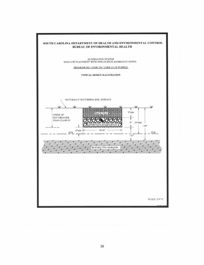
402 APPENDIX B - SYSTEM STANDARD 210/211 – SHALLOW PLACEMENT WITH 9-
INCH AGGREGATE DEPTH
402.1 SITE/PERMITTING REQUIREMENTS
(1) There must not be a zone of saturation (ZOS) within twenty-four (24) inches of the
naturally occurring soil surface.
(2) The depth to any restrictive horizon must be greater than twelve (12) inches below the
bottom of the proposed wastewater infiltration trenches.
(3) The texture in the upper eighteen (18) inches of naturally occurring soil may either be
Class I, II, III, or IV.
(4) The Long-Term Acceptance Rate for system sizing shall be based upon the most
hydraulically limiting naturally occurring soil texture from the ground surface to twelve (12)
inches below the bottom of the proposed wastewater infiltration trenches.
(5) Due to the decreased sidewall absorption area and the increased potential for ground water
28
mounding near the surface, the Equivalency Factors for these systems shall be calculated by
conventional wastewater infiltration trenches and increased by an additional factor of 0.09 times.
(6) There shall be a replacement area equivalent to at least fifty (50) percent in size of the
original system area held in reserve for system repair. This area shall have a suitable
configuration, and shall meet the minimum soil and site conditions of R. 61-56.
(7) This system must not be used on sloping sites that require serial distribution unless it can
be demonstrated that the entire wastewater infiltration trench installation (i.e., side wall to side
wall and end to end) can meet the required textural limitations and the required offsets to the
zone of saturation and restrictive horizons. Level installations on slightly sloping sites can be
considered if the above requirements can be met.
(8) This system cannot be considered for facilities with peak flow rates in excess of fifteen
hundred (1500) gallons per day.
402.2 INSTALLATION REQUIREMENTS
(1) Serial distribution is restricted (see item 7. above).
(2) The wastewater infiltration trench aggregate shall be nine (9) inches in depth and shall be
covered with at least nine (9) inches of backfill.
(3) The maximum wastewater infiltration trench width shall be thirty-six (36) inches; the
minimum width shall be eighteen (18) inches.
(4) The maximum depth of the bottom of the wastewater infiltration trench shall be eighteen
(18) inches below the naturally occurring soil surface unless it can be demonstrated that deeper
placement can meet the required textural limitations and the offsets to the zone of saturation and
restrictive horizons.
(5) Where gravity flow from the septic tank to the subsurface wastewater infiltration area is
utilized, the invert elevation of the septic tank outlet shall be installed at an elevation at least
equal to or higher than the top of the aggregate in the highest wastewater infiltration trench(es).
(6) All tree and brush removal shall be done in a manner that minimizes the disturbance or
loss of naturally occurring soil.
402.3 FINAL LANDSCAPING AND DRAINAGE
(1) Installation of drainage swales, ditches, curtain drains, and rain gutters may be required to
divert or intercept water away from the onsite wastewater system location to a positive outfall.
The septic tank and subsurface wastewater infiltration area shall be backfilled and shaped to
promote surface water runoff.
(2) A barrier to preclude parking and vehicular traffic over the system area may be required.

29
(3) Following final landscaping, seeding or sodding may be required to prevent erosion.
(4) Final approval shall be withheld until all landscaping and drainage improvements have
been satisfactorily completed.
30

31
403 APPENDIX C - SYSTEM STANDARD 220/221 – SHALLOW PLACEMENT WITH 6-
INCH AGGREGATE DEPTH
403.1 SITE/PERMITTING REQUIREMENTS
(1) There must not be a zone of saturation (ZOS) within twenty-one (21) inches of the
naturally occurring soil surface.
(2) The depth to any restrictive horizon must be greater than twelve (12) inches below the
bottom of the proposed wastewater infiltration trenches.
(3) The texture in the upper eighteen (18) inches of naturally occurring soil may either be
Class I, II, III, or IV.
(4) The Long-Term Acceptance Rate for system sizing shall be based upon the most
hydraulically limiting naturally occurring soil texture from the ground surface to twelve (12)
inches below the bottom of the proposed wastewater infiltration trenches.
(5) Due to the decreased sidewall absorption area and the increased potential for ground water
mounding near the surface, the Equivalency Factors for these systems shall be calculated by
conventional wastewater infiltration trenches and increased by an additional factor of 0.12 times.
(6) There shall be a replacement area equivalent to at least fifty (50) percent in size of the
original system area held in reserve for system repair. This area shall have a suitable
configuration, and shall meet the minimum soil and site conditions of R. 61-56.
(7) This system must not be used on sloping sites that require serial distribution unless it can
be demonstrated that the entire wastewater infiltration trench installation (i.e., side wall to side
wall and end to end) can meet the required textural limitations and the required offsets to the
zone of saturation and restrictive horizons. Level installations on slightly sloping sites can be
considered if the above limitations can be met.
(8) This system cannot be considered for facilities with peak flow rates in excess of fifteen
hundred (1500) gallons per day.
403.2 INSTALLATION REQUIREMENTS
(1) Serial distribution is restricted (see Section 403.1(7)).
(2) The wastewater infiltration trench aggregate shall be six (6) inches in depth and shall be
covered with at least nine (9) inches of backfill.
(3) The maximum wastewater infiltration trench width shall be thirty-six (36) inches; the
minimum width shall be eighteen (18) inches.
32
(4) The maximum depth of the bottom of the wastewater infiltration trench shall be fifteen
(15) inches below the naturally occurring soil surface unless it can be demonstrated that deeper
placement can meet the required textural limitations and the offsets to the zone of saturation and
restrictive horizons.
(5) Where gravity flow from the septic tank to the subsurface wastewater infiltration area is
utilized, the invert elevation of the
septic tank outlet shall be installed at an elevation at least equal to or higher than the top of the
aggregate in the highest wastewater infiltration trench(es).
(6) All tree and brush removal shall be done in a manner that minimizes the disturbance or
loss of naturally occurring soil.
403.3 FINAL LANDSCAPING AND DRAINAGE
(1) Installation of drainage swales, ditches, curtain drains, and rain gutters may be required to
divert or intercept water away from the onsite wastewater system location to a positive outfall.
The septic tank and subsurface wastewater infiltration area shall be backfilled and shaped to
promote surface water runoff.
(2) A barrier to preclude parking and vehicular traffic over the system area may be required.
(3) Following final landscaping, seeding or sodding may be required to prevent erosion.
(4) Final approval shall be withheld until all landscaping and drainage improvements have
been satisfactorily completed.
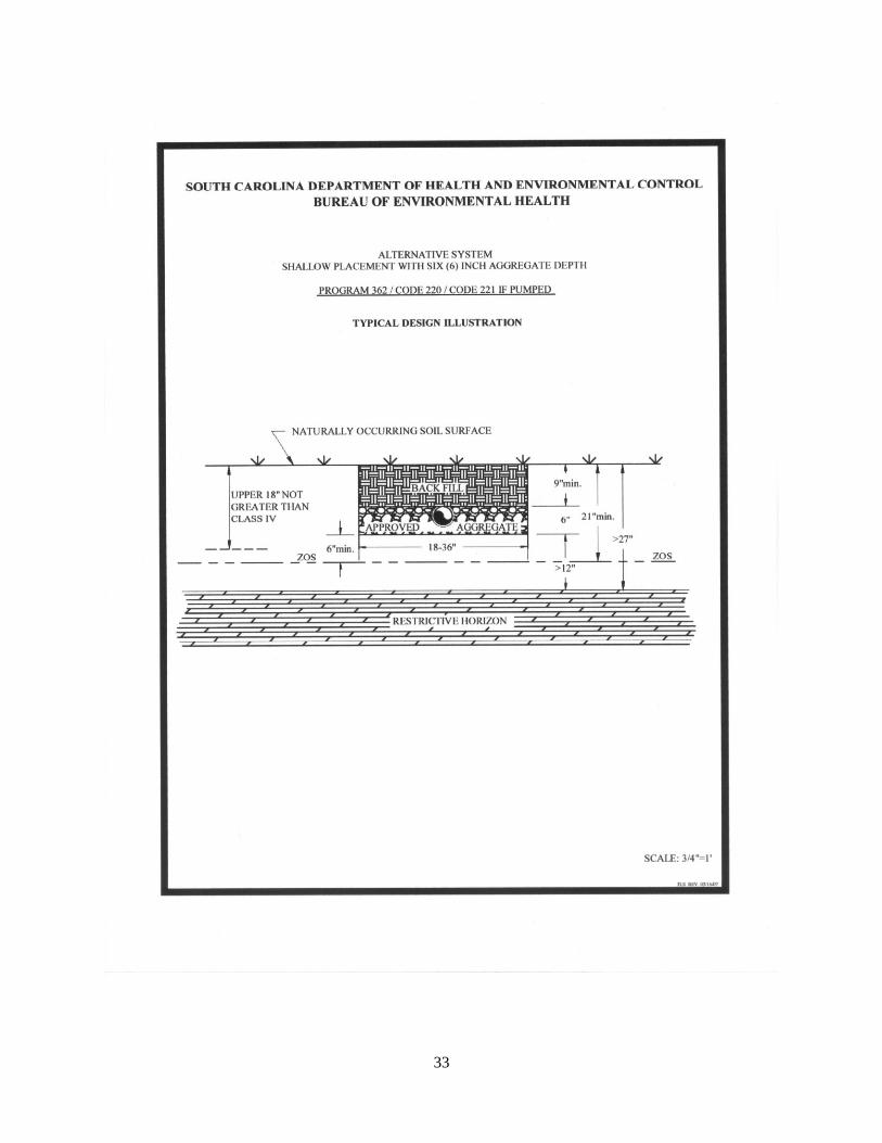
33
34
404 APPENDIX D - SYSTEM STANDARD 230/231 – SHALLOW PLACEMENT SYSTEM
WITH 14-INCH AGGREGATE DEPTH WITH FILL CAP
404.1 SITE/PERMITTING REQUIREMENTS
(1) There must not be a zone of saturation (ZOS) within twenty (20) inches of the naturally
occurring soil surface.
(2) The depth to any restrictive horizon must be greater than twelve (12) inches below the
bottom of the proposed wastewater infiltration trenches.
(3) The texture in the upper eighteen (18) inches of naturally occurring soil must be no more
limiting than Class III.
(4) This system must not be utilized on sites that require serial distribution. Level
installations on slightly sloping sites can be considered if it can be demonstrated that the entire
installation (i.e., side wall to side wall and end to end) will meet the required textural limitations
and the required offsets to the zone of saturation and restrictive horizons.
(5) The Long-Term Acceptance Rate for system sizing shall be based upon the most
hydraulically limiting naturally occurring soil texture from the ground surface to twelve (12)
inches below the bottom of the proposed wastewater infiltration trenches.
(6) The total linear footage of wastewater infiltration trenches shall be the same as that
required for conventional systems.
(7) There shall be a replacement area equivalent to at least fifty (50) percent in size of the
original system area held in reserve for system repair. This area shall have a suitable
configuration, and shall meet the minimum soil and site conditions of R. 61-56.
(8) This system cannot be considered for facilities with peak flow rates in excess of fifteen
hundred (1500) gallons per day.
404.2 INSTALLATION REQUIREMENTS
(1) The maximum wastewater infiltration trench width must not exceed thirty-six (36) inches;
the minimum width shall be eighteen (18) inches.
(2) The maximum depth of the bottom of the wastewater infiltration trench shall be fourteen
(14) inches below the naturally occurring soil surface unless it can be demonstrated that deeper
placement can meet the required textural limitations and the offsets to the zone of saturation and
restrictive horizons.
(3) The depth of the fill cap shall provide a minimum of twelve (12) inches backfill above the
top of the wastewater infiltration trench aggregate. (see attached illustration)
35
(4) Where gravity flow from the septic tank to the subsurface wastewater infiltration area is
utilized, the invert elevation of the septic tank outlet shall be installed at an elevation at least
equal to or higher than the top of the aggregate in the highest wastewater infiltration trench(es).
(5) The required fill cap must extend at least five (5) feet beyond the limits of the subsurface
wastewater infiltration trenches, and must taper to the original soil surface at a slope not to
exceed 10 percent. (see attached illustration). The required property line setback shall be
measured from the point at which the fill cap taper intersects with the natural soil surface.
(6) The required fill material must be soil texture Class I, Class II or Class III and be devoid
of extraneous debris such as organic matter, building materials, etc.
(7) The wastewater infiltration trench aggregate shall be fourteen (14) inches in depth.
(8) All tree/brush removal shall be done in a manner that minimizes the disturbance or loss of
naturally occurring soil.
404.3 FINAL LANDSCAPING AND DRAINAGE
(1) The septic tank and fill cap area shall be backfilled and shaped to promote the runoff of
surface water.
(2) Where natural surface drainage does not exist, a swale shall be constructed adjacent to the
fill cap area to divert surface water away from the onsite wastewater system to a positive outfall.
The installation of ditches, curtain drains, and rain gutters may be required to intercept and divert
water away from the onsite wastewater system location.
(3) A barrier to preclude parking and vehicular traffic over the system area may be required.
(4) Following final landscaping, seeding or sodding may be required to prevent erosion.
(5) Final approval shall be withheld until all landscaping and drainage improvements have
been satisfactorily completed.

36

37
405 APPENDIX E - SYSTEM STANDARD 240/241 – ULTRA-SHALLOW PLACEMENT
WITH 6-INCH AGGREGATE DEPTH WITH FILL CAP
405.1 SITE/PERMITTING REQUIREMENTS
(1) There must not be a zone of saturation (ZOS) within twelve (12) inches of the naturally
occurring soil surface.
(2) The depth to any restrictive horizon must be greater than twelve (12) inches below the
bottom of the proposed wastewater infiltration trenches.
(3) The soil texture in the upper eighteen (18) inches of naturally occurring soil must be no
more limiting than Class III.
(4) This system must not be utilized on sites that require serial distribution. Level installations
on slightly sloping sites can be considered if it can be demonstrated that the entire installation
(i.e., side wall to side wall and end to end) will meet the required textural limitations and the
required offsets to the zone of saturation and restrictive horizons.
(5) No part of this system can be installed within one hundred twenty-five (125) feet of the
critical area line or tidal waters as determined by the Department; or within one hundred twenty-
five (125) feet of the ordinary high water elevation within the banks of non-tidal,
environmentally sensitive waters.
(6) The Long-Term Acceptance Rate for system sizing shall be based upon the most
hydraulically limiting naturally occurring soil texture from the ground surface to twelve (12)
inches below the bottom of the proposed wastewater infiltration trenches.
(7) Due to the decreased sidewall area and the increased potential for ground water
mounding near the surface, the Equivalency Factors for these systems shall be calculated by
conventional wastewater infiltration trenches and increased by an additional factor of 0.12 times.
(8) There shall be a replacement area equivalent to at least fifty (50) percent in size of the
original system area held in reserve for system repair. This area shall have a suitable
configuration, and shall meet the minimum soil and site conditions of R. 61-56.
(9) This system cannot be considered for facilities with peak flow rates in excess of fifteen
hundred (1500) gallons per day.
405.2 INSTALLATION REQUIREMENTS
(1) The maximum wastewater infiltration trench width must not exceed thirty-six (36) inches;
the minimum width shall be 18 inches.
(2) The maximum depth of the bottom of the wastewater infiltration trench shall be six (6)
inches below the naturally occurring soil surface unless it can be demonstrated that deeper
38
placement can meet the required textural limitations and offsets to the zone of saturation and
restrictive horizons.
(3) The depth of the fill cap shall provide a minimum of twelve (12) inches backfill above the
top of the wastewater infiltration trench aggregate (see attached illustration).
(4) Where gravity flow from the septic tank to the subsurface wastewater infiltration area is
utilized, the invert elevation of the septic tank outlet shall be installed at an elevation at least
equal to or higher than the top of the aggregate in the highest wastewater infiltration trench(es).
(5) The required fill cap must extend at least five (5) feet beyond the limits of the subsurface
wastewater infiltration trenches, and must taper to the original soil surface at a slope not to
exceed of 10 percent. (see attached illustration) The required property line setback shall be
measured from the point at which the fill cap taper intersects with the natural soil surface.
(6) The required fill material must be soil texture Class I, Class II, or Class III, and be devoid
of extraneous debris such as organic matter, building materials, etc.
(7) The wastewater infiltration trench aggregate shall be six (6) inches in depth.
(8) All tree/brush removal shall be done in a manner that minimizes the disturbance or loss
of naturally occurring soil.
405.3 FINAL LANDSCAPING AND DRAINAGE
(1) The septic tank and fill cap area shall be backfilled and shaped to promote the runoff of
surface water.
(2) Where natural surface drainage does not exist, a swale shall be constructed adjacent to the
fill cap area to divert surface water away from the onsite wastewater system to a positive outfall.
The installation of ditches, curtain drains, and rain gutters may be required to intercept and divert
water away from the onsite wastewater system location.
(3) A barrier to preclude parking and vehicular traffic over the system area may be required.
(4) Following final landscaping, seeding or sodding may be required to prevent erosion.
(5) Final approval shall be withheld until all landscaping and drainage improvements have
been satisfactorily completed.
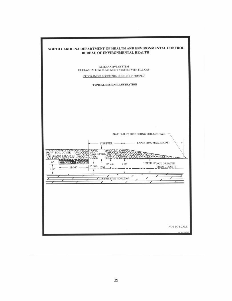
39
40
406 APPENDIX F - SYSTEM STANDARD 250/251 – RESERVOIR INFILTRATION
SYSTEM FOR SOILS WITH EXPANSIVE CLAY
406.1 SITE/PERMITTING REQUIREMENTS
(1) Rock formations must be greater than four (4) feet below the naturally occurring soil
surface.
(2) For standard installations (see Typical Design Illustration A), the wastewater infiltration
trenches must penetrate the saprolite at least six (6) inches. Also, there must be an offset greater
than twelve (12) inches between the bottom of the trenches and any rock formations. (i.e. there
must be greater than eighteen (18) inches of clean, unconsolidated saprolite below the expansive
clay layer.)
(3) If the unconsolidated saprolite layer is greater than sixty (60) inches below the naturally
occurring soil surface (see Typical Design Illustration B), item 2. (above) shall apply and clean
medium sand shall be added to the trenches so that the top of the aggregate will be twelve (12)
inches below finished grade.
(4) There must be no evidence of a zone of saturation (ZOS) in the unconsolidated saprolite
layer.
(5) The Long-Term Acceptance Rate shall not exceed 0.25 gpd/sq. ft.
(6) There shall be a replacement area equivalent to at least fifty (50) percent in size of the
original system area held in reserve for system repair. This area shall have a suitable
configuration, and shall meet the minimum soil and site conditions of R. 61-56.
(7) Sites to be considered for this system shall be evaluated using backhoe pits to describe the
soil profile.
(8) This system cannot be considered for facilities with peak flow rates in excess of fifteen
hundred (1500) gallons per day.
(a) Clean, unconsolidated saprolite shall be defined as: Soft, friable, thoroughly
decomposed rock that has formed in place by chemical weathering, retaining the fabric and
structure of the parent rock, and being devoid of expansive clay. Unconsolidated saprolite can be
dug using a hand auger or knife. Consolidated saprolite cannot be penetrated with a hand auger
or similar tool, and must be dug with a backhoe or other powered equipment.
(b) Expansive clay shall be defined as soils containing significant amounts of expansible-
layer clay minerals or smectites as evidenced in the field by classifications of Very Sticky and
Very Plastic and Structure Grades of Weak or Structureless when evaluated in accordance with
the Field Book. Such soils are considered to be unsuitable for onsite wastewater systems.
41
406.2 INSTALLATION REQUIREMENTS
(1) The aggregate depth shall be twenty-four (24) inches.
(2) The depth of medium sand will vary between zero (0) and one hundred twenty (120)
inches, depending upon the depth to the saprolite layer.
(3) The trench width shall be thirty-six (36) inches.
(4) Where gravity flow from the septic tank to the subsurface wastewater infiltration area is
utilized, the invert elevation of the septic tank outlet shall be installed at an elevation at least
equal to or higher than the top of the aggregate in the highest wastewater infiltration trench(es).
(5) The backfill shall range from twelve (12) inches to thirty-six (36) inches for standard
installations (see Typical Design Illustration A), and shall be twelve (12) inches where the depth
to saprolite is greater than sixty (60) inches below the naturally occurring soil surface (see
Typical Design Illustration B).
406.3 FINAL LANDSCAPING AND DRAINAGE
(1) On sites where there is evidence of a zone of saturation at the soil-expansive clay
interface, a curtain drain must be placed upslope along a contour and must extend the entire
length of the subsurface wastewater infiltration area. The curtain drain shall extend a minimum
of six (6) inches into the expansive clay layer. The septic tank and subsurface wastewater
infiltration area shall be backfilled and shaped to promote surface water runoff.
(2) Following final landscaping, seeding or sodding may be required to prevent erosion.
(3) Final approval shall be withheld until all landscaping and drainage improvements have
been satisfactorily completed.
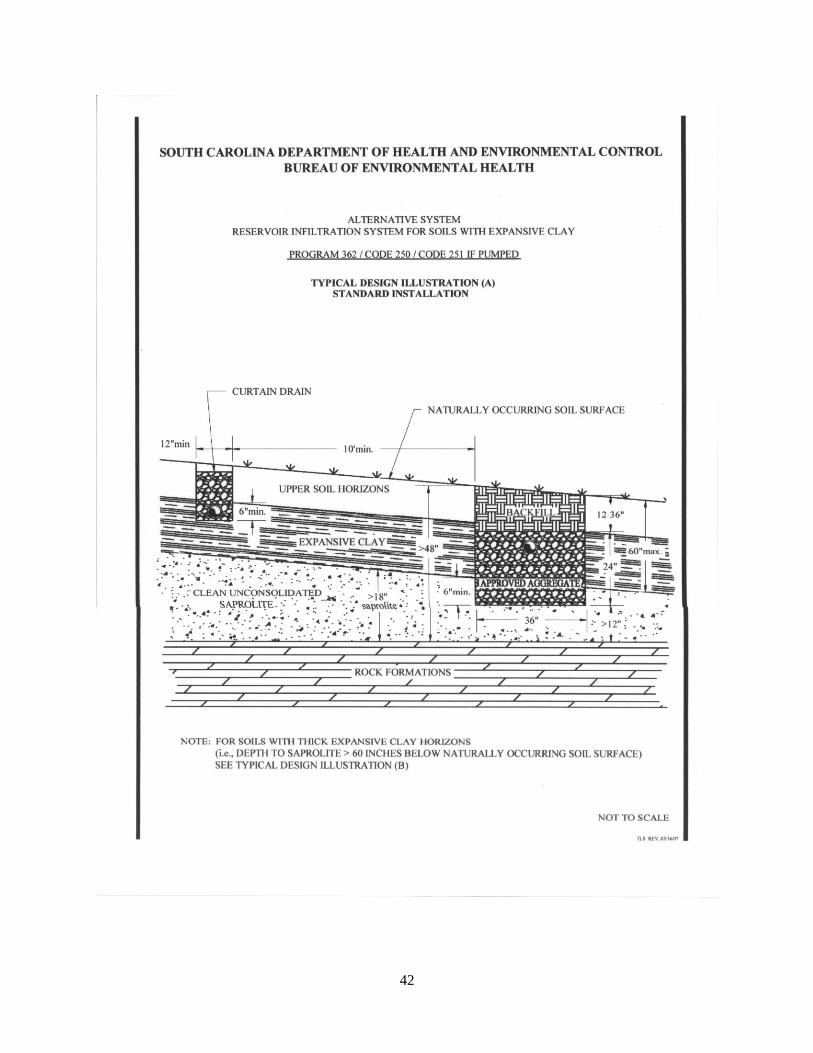
42
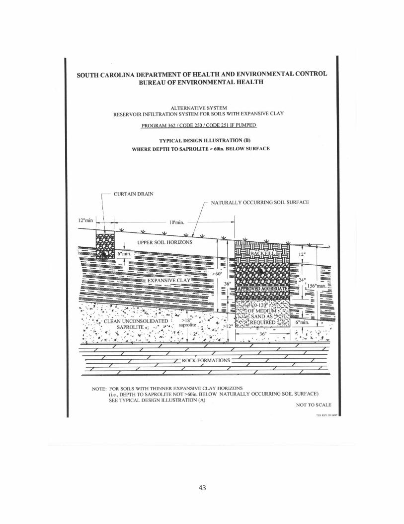
43

44
407 APPENDIX G - SYSTEM STANDARD 260/261 – 9-INCH SHALLOW PLACEMENT
SYSTEM WITH FILL CAP
407.1 SITE/PERMITTING REQUIREMENTS
(1) There must not be a zone of saturation (ZOS) within fifteen (15) inches of the naturally
occurring soil surface.
(2) The depth to any restrictive horizon must be greater than twelve (12) inches below the
bottom of the proposed wastewater infiltration trenches.
(3) The texture in the upper eighteen (18) inches of naturally occurring soil must be no more
limiting than Class III.
(4) This system must not be utilized on sites that require serial distribution. Level installations
on slightly sloping sites can be considered if it can be demonstrated that the entire installation
(i.e., side wall to side wall and end to end) will meet the required textural limitations and the
required offsets to the zone of saturation and restrictive horizons.
(5) The Long-Term Acceptance Rate for system sizing shall be based upon the most
hydraulically limiting naturally occurring soil texture from the ground surface to twelve (12)
inches below the bottom of the proposed wastewater infiltration trenches.
(6) Due to the decreased sidewall absorption area and the increased potential for ground water
mounding near the surface, the Equivalency Factors for these systems shall be calculated by
conventional wastewater infiltration trenches and increased by an additional factor of 0.09 times.
(7) No part of this system can be installed within 125 feet of the critical area line or tidal
waters as determined by the Department; or within 125 feet of the ordinary high water elevation
within the banks of non-tidal, environmentally sensitive waters.
(8) There shall be a replacement area equivalent to at least fifty (50) percent in size of the
original system area held in reserve for system repair. This area shall have a suitable
configuration, and shall meet the minimum soil and site conditions of R. 61-56.
(9) This system cannot be considered for facilities with peak flow rates in excess of fifteen
hundred (1500) gallons per day.
407.2 INSTALLATION REQUIREMENTS
(1) The maximum wastewater infiltration trench width must not exceed thirty-six (36) inches;
the minimum width shall be eighteen (18) inches.
(2) The maximum depth of the bottom of the wastewater infiltration trench shall be nine (9)
inches below the naturally occurring soil surface unless it can be demonstrated that deeper
45
placement can meet the required textural limitations and the offsets to the zone of saturation and
restrictive horizons.
(3) Where gravity flow from the septic tank to the subsurface wastewater infiltration area is
utilized, the invert elevation of the septic tank outlet shall be installed at an elevation at least
equal to or higher than the top of the aggregate in the highest wastewater infiltration trench(es).
(4) The depth of the fill cap shall provide a minimum of twelve (12) inches backfill above the
top of the wastewater infiltration trench aggregate (see attached illustration).
(5) The required fill cap must extend at least five (5) feet beyond the limits of the wastewater
infiltration trenches, and must taper to the original soil surface at a slope not to exceed 10 percent
(see attached illustration). The required property line setback shall be measured from the point at
which the fill cap taper intersects with the naturally occurring soil surface.
(6) The required fill material must be soil texture Class I, Class II, or Class III, and be devoid
of extraneous debris such as organic matter, building materials, etc.
(7) The wastewater infiltration trench aggregate shall be nine (9) inches in depth.
(8) All trees/brush removal shall be done in a manner that minimizes the disturbance or loss
of naturally occurring soil.
407.3 FINAL LANDSCAPING AND DRAINAGE
(1) The septic tank and fill cap area shall be backfilled and shaped to promote the runoff of
surface water.
(2) Where natural surface drainage does not exist, a swale shall be constructed adjacent to the
fill cap area to divert surface water away from the onsite wastewater system to a positive outfall.
The installation of ditches, curtain drains, and rain gutters may be required to intercept and divert
water away from the onsite wastewater system location.
(3) A barrier to preclude parking and vehicular traffic over the system area may be required.
(4) Following final landscaping, seeding or sodding may be required to prevent erosion.
(5) Final approval shall be withheld until all landscaping and drainage improvements have
been satisfactorily completed.

46
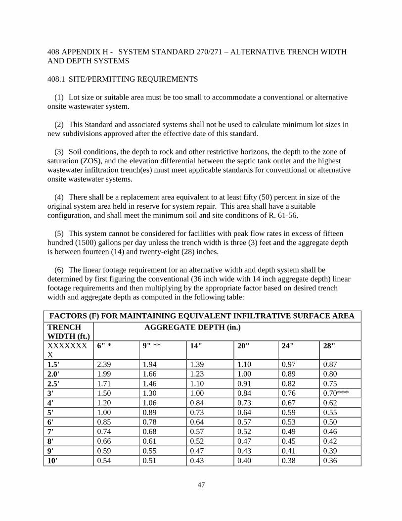
47
408 APPENDIX H - SYSTEM STANDARD 270/271 – ALTERNATIVE TRENCH WIDTH
AND DEPTH SYSTEMS
408.1 SITE/PERMITTING REQUIREMENTS
(1) Lot size or suitable area must be too small to accommodate a conventional or alternative
onsite wastewater system.
(2) This Standard and associated systems shall not be used to calculate minimum lot sizes in
new subdivisions approved after the effective date of this standard.
(3) Soil conditions, the depth to rock and other restrictive horizons, the depth to the zone of
saturation (ZOS), and the elevation differential between the septic tank outlet and the highest
wastewater infiltration trench(es) must meet applicable standards for conventional or alternative
onsite wastewater systems.
(4) There shall be a replacement area equivalent to at least fifty (50) percent in size of the
original system area held in reserve for system repair. This area shall have a suitable
configuration, and shall meet the minimum soil and site conditions of R. 61-56.
(5) This system cannot be considered for facilities with peak flow rates in excess of fifteen
hundred (1500) gallons per day unless the trench width is three (3) feet and the aggregate depth
is between fourteen (14) and twenty-eight (28) inches.
(6) The linear footage requirement for an alternative width and depth system shall be
determined by first figuring the conventional (36 inch wide with 14 inch aggregate depth) linear
footage requirements and then multiplying by the appropriate factor based on desired trench
width and aggregate depth as computed in the following table:
FACTORS (F) FOR MAINTAINING EQUIVALENT INFILTRATIVE SURFACE AREA
TRENCH
WIDTH (ft.)
AGGREGATE DEPTH (in.)
XXXXXXX
X
6" * 9" ** 14" 20" 24" 28"
1.5' 2.39 1.94
1.39 1.10 0.97 0.87
2.0' 1.99
1.66
1.23 1.00 0.89 0.80
2.5' 1.71
1.46 1.10 0.91 0.82 0.75
3' 1.50 1.30 1.00 0.84 0.76 0.70***
4' 1.20 1.06 0.84 0.73 0.67 0.62
5' 1.00 0.89 0.73 0.64 0.59 0.55
6' 0.85 0.78 0.64 0.57 0.53 0.50
7' 0.74 0.68 0.57 0.52 0.49 0.46
8' 0.66
0.61 0.52 0.47 0.45 0.42
9' 0.59 0.55 0.47 0.43 0.41 0.39
10' 0.54 0.51 0.43 0.40 0.38 0.36

48
FACTORS (F) FOR MAINTAINING EQUIVALENT INFILTRATIVE SURFACE AREA
TRENCH
WIDTH (ft.)
AGGREGATE DEPTH (in.)
XXXXXXX
X
6" * 9" ** 14" 20" 24" 28"
F = 5.34 ft2/ ft____
2 (SwD / 12) + TW
* Factors reflect a 12 percent
increase
** Factors reflect a 9 percent
increase
*** Use system code 360/380
Where, 5.34 ft2/ft = total infiltrative surface area per linear foot
of conventional type trench 36 in. wide, 14 in. deep
SwD = Side Wall Depth (in.)
TW = Trench Width (ft)
408.2 INSTALLATION REQUIREMENTS
(1) Trench widths shall always be kept as narrow as possible and shall not exceed 10 feet.
(2) The aggregate depth shall be between six (6) inches and twenty-eight (28) inches when
considering trench widths ranging from one and one-half (1½) to ten (10) feet (see chart). The
aggregate depth may be increased to a maximum of forty-two (42) inches, provided the trench
width does not exceed thirty-six (36) inches (Note: in these cases, the equivalency formula
should be utilized to determine the appropriate factor (F) when considering aggregate depths
between 28 and 42 inches). All trenches shall be covered with at least nine (9) inch of backfill.
(3) Methods of construction which preclude vehicular compaction of the trench bottom must
always be utilized.
408.3 FINAL LANDSCAPING AND DRAINAGE
(1) Installation of drainage swales, ditches, diversion drains, or rain gutters may be required
to divert or intercept water away from the onsite wastewater system location. The septic tank
and subsurface wastewater infiltration area shall be backfilled and shaped to promote surface
water runoff.
(2) A barrier to preclude parking and vehicular traffic over the area of the system may be
required.
(3) Following final landscaping, seeding or sodding may be required to prevent erosion.
(4) Final approval shall be withheld until all landscaping and drainage improvements have
been satisfactorily completed.
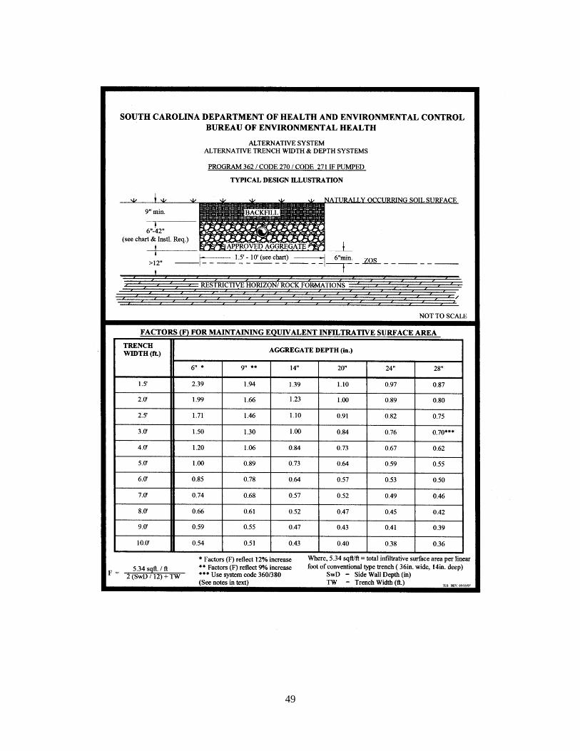
49

50
409 APPENDIX I - SYSTEM STANDARD 280/281 – RESERVOIR INFILTRATION
SYSTEM FOR SOILS WITH EXPANSIVE CLAY SHALLOW ROCK FORMATIONS
409.1 SITE/PERMITTING REQUIREMENTS
(1) Rock formations must be rippable (see Section 409.1(9)(b)) to a depth greater than four
(4) feet below the naturally occurring soil surface.
(2) The soil wastewater infiltration trenches must penetrate the saprolite at least six (6)
inches, and there must be an offset greater than twelve (12) inches between the trench bottoms
and any rock formations (i.e., there must be at least six (6) inches of clean, unconsolidated
saprolite below the expansive clay layer, and medium sand may be added to the excavation to
achieve an offset from rock that exceeds twelve (12) inches).
(3) There must be no evidence of a zone of saturation (ZOS) in the unconsolidated saprolite
layer.
(4) The Long-Term Acceptance Rate shall not exceed 0.20-gpd/sqft.
(5) Effluent discharged to this system must receive a higher degree of treatment than that
provided by a conventional septic tank. (i.e. two compartment septic tank or two septic tanks in
series)
(6) There shall be a replacement area equivalent to at least fifty (50) percent in size of the
original system area held in reserve for system repair. This area shall have a suitable
configuration, and shall meet the minimum soil and site conditions of R. 61-56.
(7) No part of this system can be installed within one hundred twenty-five (125) feet of the
ordinary high water elevation within the banks of environmentally sensitive waters.
(8) Sites to be considered for this system shall be evaluated using backhoe pits to describe the
soil profile.
(9) This system cannot be considered for facilities with peak flow rates in excess of fifteen
hundred (1500) gallons per day.
(a) Clean, unconsolidated saprolite shall be defined as: Soft, friable thoroughly
decomposed rock that has formed in place by chemical weathering, retaining the fabric and
structure of the parent rock, and being devoid expansive clay. Unconsolidated saprolite can be
dug using a hand auger or knife. Consolidated saprolite cannot be penetrated with a hand auger
or similar tool, and must be dug with a backhoe or other powered equipment.
(b) Rippable rock shall be defined as formations that can be readily dug with a standard
rubber-tired backhoe.
51
(c) Expansive clay shall be defined as soils containing significant amounts of expansible-
layer clay minerals (smectites) as evidenced in the field by classifications of Very Sticky and
Very Plastic and Structure Grades of Weak or Structureless when evaluated in accordance with
the Field Books. Such soils are considered to be unsuitable for onsite wastewater systems.
409.2 INSTALLATION REQUIREMENTS
(1) The aggregate depth shall be at least twenty-four (24) inches.
(2) The trench width shall be thirty-six (36) inches.
(3) Where gravity flow from the septic tank to the subsurface wastewater infiltration area is
utilized, the invert elevation of the septic tank outlet shall be installed at an elevation at least
equal to or higher than the top of the aggregate in the highest wastewater infiltration trench(es).
409.3 FINAL LANDSCAPING AND DRAINAGE
(1) On sites where there is evidence of a zone of saturation at the soil-expansive clay
interface, a curtain drain must be placed upslope along a contour and must extend the entire
length of the subsurface wastewater infiltration area. The curtain drain shall extend a minimum
of six (6) inches into the expansive clay layer. Also, the septic tank and subsurface wastewater
infiltration area shall be backfilled and shaped to promote surface water runoff.
(2) Final approval shall be withheld until all landscaping, drainage, and other requirements
have been satisfactorily completed.
(3) Following final landscaping, seeding or sodding may be required to prevent erosion.
(4) Final approval shall be withheld until all landscaping and drainage improvements have
been satisfactorily completed.
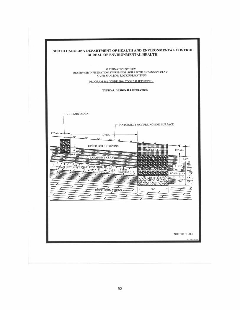
52
53
410 APPENDIX J - SYSTEM STANDARD 370/371 – SHALLOW PLACEMENT WITH FILL
CAP FOR SITES WITH SHALLOW CLASS IV SOIL
410.1 SITE/PERMITTING REQUIREMENTS
(1) There must not be a zone of saturation (ZOS) within twelve (12) inches of the naturally
occurring soil surface.
(2) The depth to any restrictive horizon must be greater than twelve (12) inches below the
bottom of the proposed wastewater infiltration trenches.
(3) This system must not be utilized on sites that require serial distribution. Level installations
on slightly sloping sites can be considered if it can be demonstrated that the entire installation
(i.e., side wall to side wall and end to end) will meet the required textural limitations and the
required offsets to the zone of saturation and restrictive horizons.
(4) No part of this system can be installed within 125 feet of the ordinary high water elevation
within the banks of environmentally sensitive waters.
(5) This system may be considered for installation on contiguous lots in new subdivisions
approved after the effective date of this standard provided a setback of at least seventy-five (75)
feet is maintained between the system and all adjacent property lines. The seventy-five (75) foot
setback shall be measured from the point at which the fill cap taper intersects with the naturally
occurring soil surface.
(6) This system cannot be considered for facilities with peak sewage flow rates in excess of
four hundred eighty (480) gallons per day. In addition, this system shall not be considered for
facilities requiring grease traps.
(7) There shall be a replacement area equivalent to at least fifty (50) percent in size of the
original system area held in reserve for system repair. This area shall have a suitable
configuration, and shall meet the minimum soil and site conditions of R. 61-56.
(8) The Long-Term Acceptance Rate for system sizing shall be based upon the most
hydraulically limiting naturally occurring soil texture from the ground surface to twelve (12)
inches below the bottom of the proposed wastewater infiltration trenches.
410.2 INSTALLATION REQUIREMENTS
(1) This system cannot utilize serial distribution.
(2) Effluent discharged to this system must receive a higher degree of treatment than that
provided by a conventional septic tank (i.e. two compartment septic tank or two septic tanks in
series).
54
(3) Where gravity flow from the septic tank to the subsurface wastewater infiltration area is
utilized, the invert elevation of the septic tank outlet shall be installed at an elevation at least
equal to or higher than the top of the aggregate in the highest wastewater infiltration trench(es).
(4) The required fill cap must extend at least five (5) feet beyond the limits of the wastewater
infiltration trenches, and it must taper to the original soil surface at a slope not to exceed 10
percent (see attached sketch). The required seventy-five (75) feet property line setback shall be
measured from the point at which the fill cap taper intersects with the naturally occurring soil
surface.
(5) The required fill material must be soil texture Class I, Class II or Class III and be void of
extraneous debris such as organic matter, building materials, etc.
(6) The depth of the fill cap shall provide a minimum of twelve (12) inches backfill above the
top of the wastewater infiltration trench aggregate.
(7) The wastewater infiltration trench width shall be thirty-six (36) inches.
(8) All tree and brush removal shall be done in a manner that minimizes the disturbance or
loss of naturally occurring soil.
(9) The following criteria shall be utilized in the selection and design of these systems:
Note: refer to the design sketch (typical) for detail.
410.3 FINAL LANDSCAPING AND DRAINAGE
(1) The septic tank and fill cap area shall be backfilled and shaped to promote the runoff of
surface water.
(2) Where natural surface drainage does not exist, a swale shall be constructed adjacent to the
filled area to divert surface water away from the onsite wastewater system to a positive outfall.
The installation of ditches, curtain drains, and rain gutters may be required to intercept and divert
water away from the onsite wastewater system location.
Depth to ZOS
(Inches)
Depth to Class IV
Soil (Inches)
Amount of Imported
Fill Cap/Aggregate
Depth (Inches)
Extension Factor
12 18 12/6 1.5
13 17 12/6 1.5
14 16 12/6 1.5
15 15 12/9 1.3
16 14 12/9 1.3
17 13 12/9 1.3
18 12 12/9 1.3
19 11 12/9 1.3
20 10 12/9 1.3

55
(3) A barrier to preclude parking and vehicular traffic over the system area may be required.
(4) Following final landscaping, seeding or sodding may be required to prevent erosion.
(5) Final approval shall be withheld until all landscaping and drainage improvements have
been satisfactorily completed.
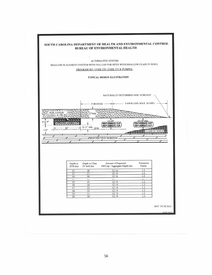
56

57
411 APPENDIX K - SYSTEM STANDARD 380/381 – DOUBLE AGGREGATE DEPTH
WASTEWATER INFILTRATION TRENCHES
411.1 SITE/PERMITTING REQUIREMENTS
(1) Use of the double aggregate depth option must be restricted to soils that meet all textural
limitations and required offsets to the zone of saturation (ZOS) and restrictive horizons.
(2) Systems incorporating the double aggregate depth option shall be loaded on the basis of
the most hydraulically limiting naturally occurring soil texture from the ground surface to twelve
(12) inches below the bottom of the proposed wastewater infiltration trenches.
(3) In order to maintain the same total absorptive area as that provided by conventional
aggregate depth systems, the equivalent linear footage requirement for thirty-six (36) inch wide
double aggregate depth trenches shall be determined by multiplying the conventional trench
requirement by a factor of 0.7.
(4) There shall be a replacement area equivalent to at least fifty (50) percent in size of the
original system area held in reserve for system repair. This area shall have a suitable
configuration, and shall meet the minimum soil and site conditions of R. 61-56.
411.2 INSTALLATION REQUIREMENTS
(1) The wastewater infiltration trench aggregate shall be twenty-eight (28) inches in depth,
and shall be placed so as to provide twenty (20) inches of aggregate below the pipe, five (5)
inches beside the pipe, and three (3) inches above the pipe. The aggregate shall be covered with
at least nine (9) inches of backfill.
(2) The wastewater infiltration trench width shall be thirty-six (36) inches.
(3) Where gravity flow from the septic tank to the subsurface wastewater infiltration area is
utilized, the invert elevation of the septic tank outlet shall be installed at an elevation at least
equal to or higher than the top of the aggregate in the highest wastewater infiltration trench(es).
411.3 FINAL LANDSCAPING AND DRAINAGE
(1) Installation of drainage swales, ditches, curtain drains, and rain gutters may be required to
divert or intercept water away from the onsite wastewater system location. The septic tank and
subsurface wastewater infiltration area shall be backfilled and shaped to promote surface water
runoff.
(2) Following final landscaping, seeding or sodding may be required to prevent erosion.
(3) Final approval shall be withheld until all landscaping and drainage improvements have
been satisfactorily completed.
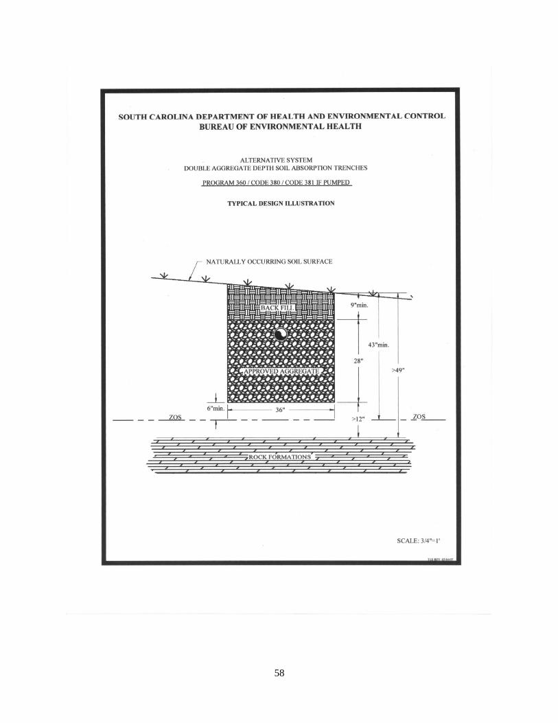
58

59
412 APPENDIX L - SYSTEM STANDARD 420/421 – MOUNDED INFILTRATION
SYSTEM
412.1 SITE/PERMITTING REQUIREMENTS
(1) The texture in the upper twelve (12) inches of naturally occurring soil must be Class I or
Class II.
(2) The soil texture in the permeable substratum must be no more limiting than Class II.
(3) There must not be a zone of saturation (ZOS) within six (6) inches of the naturally
occurring soil surface.
(4) The depth to any restrictive horizon must be greater than twelve (12) inches below the
bottom of the proposed wastewater infiltration trenches.
(5) There shall be a replacement area equivalent to at least fifty (50) percent in size of the
original system area held in reserve for system repair. This area shall have a suitable
configuration, and shall meet the minimum soil and site conditions of R. 61-56.
(6) Prior to permitting the onsite wastewater system, delineation of any affected jurisdictional
wetlands may be required. Should any part of the proposed onsite wastewater system be located
in jurisdictional wetlands, approval from the appropriate permitting agency(s) (i.e., US Army
Corp. of Engineers, SCDHEC OCRM, etc.) shall be received, and proof of such provided to the
Department.
(7) No part of this system can be installed within 125 feet of the critical area line or tidal
waters as determined by the Department; or within 125 feet of the ordinary high water elevation
within the banks of non-tidal, environmentally sensitive waters.
(8) This system cannot be considered for facilities with peak flow rates in excess of four
hundred eighty (480) gallons per day. In addition, this system shall not be considered for
facilities requiring grease traps.
(9) This system may not be installed on sites that flood.
(10) This system must not be utilized on sites that require serial distribution. Level
installations on slightly sloping sites can be considered if it can be demonstrated that the entire
installation (i.e., side wall to side wall and end to end) will meet the required textural limitations
and the required offsets to the zone of saturation and restrictive horizons.
(11) The total linear footage of six (6) inch deep, thirty-six (36) inch wide wastewater
infiltration trenches shall be increased by 100 percent over that which would be required for
conventional trenches, as determined by the Long-Term Acceptance Rate of the permeable
substratum.

60
(12) This system may be considered for installation on contiguous lots in new subdivisions
approved after the effective date of this standard provided a setback of at least seventy-five (75)
feet is maintained between the system and all adjacent property lines. The seventy-five (75) foot
setback shall be measured from the point at which the fill cap taper intersects with the naturally
occurring soil surface.
412.2 INSTALLATION REQUIREMENTS
(1) Site Preparation
(a) The naturally occurring soil surface underlying the area of the wastewater infiltration
trenches shall be thoroughly tilled and mixed with the imported medium sand to a depth of six
(6) inches.
(b) All tree and brush removal shall be done in a manner that minimizes the disturbance or
loss of naturally occurring soil.
(2) Fill and System (see ref. sketch)
(a) The fill cap and buffer shall be Class I, Class II, or Class III.
(b) The depth of the fill cap shall provide a minimum of twelve (12) inches backfill above
the top of the wastewater infiltration trench aggregate (see ref. sketch).
(c) Where gravity flow from the septic tank to the subsurface wastewater infiltration area is
utilized, the invert elevation of the septic tank outlet shall be installed at an elevation at least
equal to or higher than the top of the aggregate in the highest wastewater infiltration trench(es).
(d) The fill buffer shall be at least fifteen (15) feet in width.
(e) The fill taper shall be at least twenty (20) feet in width.
(f) The required property line setback shall be measured from the point at which the fill cap
taper intersects with the naturally occurring soil surface.
(g) The total fill depth, excluding the taper zone, shall be at least eighteen (18) inches
above the naturally occurring soil surface.
(h) The wastewater infiltration trenches shall be installed in a Class I fill pad at least six (6)
inches in depth, which extends five (5) feet beyond the trenches in all directions.
(i) The wastewater infiltration trenches require a total aggregate depth of six (6) inches.
(j) The wastewater infiltration trench width shall be thirty-six (36) inches.
61
(k) Infiltration trenches shall penetrate the permeable substratum and shall be at least two
(2) feet in width containing USDA medium sand, washed concrete sand, or other material
approved by the Department.
(l) Effluent discharged to this system must receive a higher degree of treatment than that
provided by a conventional septic tank (i.e. two compartment septic tank or two septic tanks in
series).
412.3 FINAL LANDSCAPING AND DRAINAGE
(1) The septic tank and fill cap area shall be backfilled and shaped to promote the runoff of
surface water.
(2) Where natural surface drainage does not exist, a swale shall be constructed adjacent to the
filled area to divert surface water away from the onsite wastewater system to a positive outfall.
The installation of ditches, curtain drains, and rain gutters may be required to intercept and divert
water away from the onsite wastewater system location.
(3) A barrier to preclude parking and vehicular traffic over the system area may be required.
(4) Following final landscaping, seeding or sodding may be required to prevent erosion.
(5) Final approval shall be withheld until all landscaping and drainage improvements have
been satisfactorily completed.
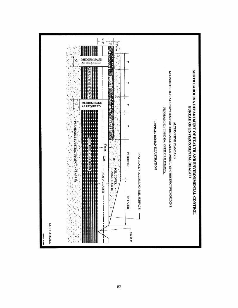
62

63
413 APPENDIX M - SYSTEM STANDARD 431 – MOUNDED FILL SYSTEM
413.1 SITE/PERMITTING REQUIREMENTS
(1) This system shall not be used on sites that are subject to flooding.
(2) The texture in the upper eighteen (18) inches of naturally occurring soil must be Class I or
Class II.
(3) The absorption bed within the mound shall be sized on the Long-Term Acceptance Rate
of the most limiting texture in the upper eighteen (18) inches of naturally occurring soil.
(4) The linear footage of the absorption bed shall be determined in accordance with Standard
270.
(5) The absorption bed width shall be minimum of five (5) feet and a maximum of 10 feet.
(6) Mounded fill systems must not be placed on sites with a slope in excess of three (3)
percent.
(7) No part of this system can be installed within 125 feet of the critical area line or tidal
waters as determined by the Department; or within 125 feet of the ordinary high water elevation
within the banks of non-tidal, environmentally sensitive waters. Because of the long buffer, side
slope, fill pad, and taper associated with this system, the one hundred twenty-five (125) foot
setback shall be measured from the outer edge of the aggregate bed within the mound.
(8) There shall be a replacement area equivalent to at least fifty (50) percent in size of the
original system area held in reserve for system repair. This area shall have a suitable
configuration, and shall meet the minimum soil and site conditions of R. 61-56.
(9) Prior to permitting the onsite wastewater system, delineation of any affected jurisdictional
wetlands may be required. Should any part of the proposed onsite wastewater system be located
in jurisdictional wetlands, approval from the appropriate permitting agency(s) (i.e., US Army
Corp. of Engineers, SCDHEC Ocean and Coastal Resource Management, etc.) shall be received
and proof of such provided to the Department.
(10) This system cannot be considered for facilities with peak flow rates in excess of four
hundred eighty (480) gallons per day. In addition, this system shall not be considered for
facilities requiring grease traps.
(11) Effluent discharged to this system must receive a higher degree of treatment than that
provided by a conventional septic tank (i.e. two compartment septic tank or two septic tanks in
series).
(12) This system may be considered for installation on contiguous lots in new subdivisions
approved after the effective date of this standard provided a setback of at least seventy-five
64
(75)_feet is maintained between the system and all adjacent property lines. Because of the long
buffer, side slope, fill pad, and taper associated with this system, the seventy-five (75) foot
setback shall be measured from the outer edge of the aggregate bed within the mound.
413.2 INSTALLATION REQUIREMENTS
(1) Site Preparation
(a) If present within eighteen (18) inches of the naturally occurring soil surface, organic
material and restrictive horizons must be removed from beneath the mound and replaced with
USDA medium sand, washed concrete sand, or an equivalent material approved by the
Department. The replacement area must extend five (5) feet in all directions beyond the edges of
the aggregate filled absorption bed.
(b) The naturally occurring soil surface underlying the mound shall be thoroughly tilled and
mixed with the imported mound fill material to a depth of six (6) inches.
(2) Mound/Absorption Bed Requirements
(a) Low Pressure Pipe Distribution (LPP) must be utilized to preclude localized hydraulic
overloading of the imported fill material and to minimize the impact on the shallow zone of
seasonal saturation.
(b) There must be at least twenty-four (24) inches of medium sand placed between the
naturally occurring soil surface and the bottom of the absorption bed. Also, the bottom surface
of the absorption bed must be placed at least twenty-four (24) inches above the zone of
saturation.
(c) If the slope of the site in the proposed mound area is one (1) percent or less, then the
mound shall be placed on a twelve (12) inch fill pad which must extend twenty (20) feet beyond
the mound in all directions. If the slope of the site in the proposed mound area is greater than
one (1) percent but less than or equal to three (3) percent, then the mound shall be placed on a
twelve (12) inch deep fill pad which must extend twenty (20) feet beyond the mound area on the
sides of the mound; forty (40) feet beyond the mound area on the down slope side of the mound;
with no fill pad required on the upslope side of the mound.
(d) The mound and fill pad material shall be USDA medium sand, washed concrete sand, or
other equivalent material approved by the Department.
(e) The depth of the fill cap material above the absorption bed shall be nine (9) to fifteen
(15) inches of soil texture Class II or III. Sod may be substituted for four (4) inches of this
portion of the fill cap material. (see attached illustration).
(f) The depth of the fill cap material above the mound side-slope, the twelve (12) inch deep
fill pad, and the taper shall be at least four (4) inches of soil texture Class II or III. Sod may be
substituted for this portion of the fill cap material. (see attached illustration).
65
(g) A 1:2 maximum slope is required if the mound side-slope and taper are sodded.
(h) A 1:4 maximum slope is required if the mound side-slope and taper are mulched and
seeded.
(3) Final Landscaping And Drainage Requirements
(a) The septic tank and mound area shall be backfilled and shaped to promote the runoff of
surface water.
(b) Where natural surface drainage does not exist, a swale shall be constructed adjacent to
the filled area to divert surface water away from the onsite wastewater system to a positive
outfall. The installation of ditches, curtain drains, and rain gutters may be required to intercept
and divert water away from the onsite wastewater system location.
(c) A barrier to preclude parking and vehicular traffic over the system area may be
required.
(d) Following final landscaping, seeding or sodding may be required to prevent erosion.
(e) Final approval shall be withheld until all landscaping and drainage improvements have
been satisfactorily completed.

66
67
414 APPENDIX N - SYSTEM STANDARD 601 – ELEVATED INFILTRATION SYSTEM
414.1 SITE/PERMITTING REQUIREMENTS
(1) The texture in the upper eighteen (18) inches of naturally occurring soil must be Class I or
Class II.
(2) The filter shall not be placed on slopes greater than three (3) percent.
(3) This system cannot be considered for facilities with peak flow rates in excess of four
hundred eighty (480) gallons per day. In addition, this system shall not be considered for
facilities requiring grease traps.
(4) There shall be a buffer of at least fifty (50) feet surrounding and separating the system
from all adjacent property lines. This buffer shall be measured from the retaining wall.
(5) There shall be a replacement area equivalent to at least fifty (50) percent in size of the
original system area held in reserve for system repair. This area shall have a suitable
configuration, and shall meet the minimum soil and site conditions of R. 61-56.
(6) This system shall not be placed on sites that flood.
(7) No part of this system can be installed within 125 feet of the critical area line or tidal
waters as determined by the Department; or within 125 feet of the ordinary high water elevation
within the banks of non-tidal, environmentally sensitive waters.
(8) Prior to permitting the onsite wastewater system, delineation of any affected jurisdictional
wetlands may be required. Should any part of the proposed onsite wastewater system be located
in jurisdictional wetlands, approval from the appropriate permitting agency(s) (i.e., US Army
Corp. of Engineers, SCDHEC Ocean and Coastal Resource Management, etc.) shall be received,
and proof of such provided to the Department. The absorption bed shall be sized on the most
limiting soil texture class in the upper eighteen (18) inches of naturally occurring soil.
(9) The total bottom area of the filter must be increased by fifty (50) percent above that
required for conventional trenches.
(10) This system may be considered for installation on contiguous lots in new subdivisions
approved after the effective date of this standard provided a setback of at least seventy-five (75)
feet is maintained between the system and all adjacent property lines. The seventy-five (75) foot
setback shall be measured from the point at which the retaining wall intersects the naturally
occurring soil surface.
414.2 INSTALLATION REQUIREMENTS
(1) Site Preparation

68
(a) If present within eighteen (18) inches of the naturally occurring soil surface, organic
material and restrictive horizons must be removed from beneath the filter and replaced with
USDA medium sand, washed concrete sand, or an equivalent material approved by the
Department.
(b) The naturally occurring soil surface underlying the filter shall be thoroughly tilled and
mixed with the imported filter material to a depth of six (6) inches.
(2) System Requirements
(a) The filter must be constructed to a height of at least thirty-six (36) inches above the
original grade, with the sewage effluent passing through at least twenty-four (24) inches of filter
material.
(b) The filter material shall be USDA medium sand, washed concrete sand or other material
approved by the Department.
(c) The filter retaining wall shall extend at least four (4) inches above the surface of the
filter material and shall penetrate the naturally occurring soil surface at least four (4) inches.
(d) The filter retaining wall shall be constructed in accordance with the accompanying
design illustrations.
(e) Effluent discharged to this system must receive a higher degree of treatment than that
provided by a conventional septic tank (i.e., two compartment septic tank or two septic tanks in
series).
(f) The top of the filter shall be capped with Class II or Class III soil, and shall slope from
center to edges in order to promote surface runoff.
(3) Distribution Requirements
(a) Low Pressure Pipe Distribution (LPP) must be utilized to preclude localized hydraulic
overloading of the imported fill material and to minimize the impact on the shallow zone of
saturation.
(b) Pump design shall be in accordance with Department standards.
414.3 FINAL LANDSCAPING AND DRAINAGE REQUIREMENTS
(1) Fill material shall be placed around the outside of the filter to a depth of 1 foot, and shall
slope to original grade at a point five (5) feet from the retaining wall.
(2) The septic tank and filter area shall be backfilled and shaped to promote the runoff of
surface water.
69
(3) Where natural surface drainage does not exist, a swale shall be constructed adjacent to the
filter to divert surface water away from the onsite wastewater system to a positive outfall. The
installation of ditches, curtain drains, and/or rain gutters may be required to intercept and divert
water away from the onsite wastewater system location.
(4) Following final landscaping, seeding or sodding may be required to prevent erosion.
(5) Final approval shall be withheld until all landscaping and drainage improvements have
been satisfactorily completed.
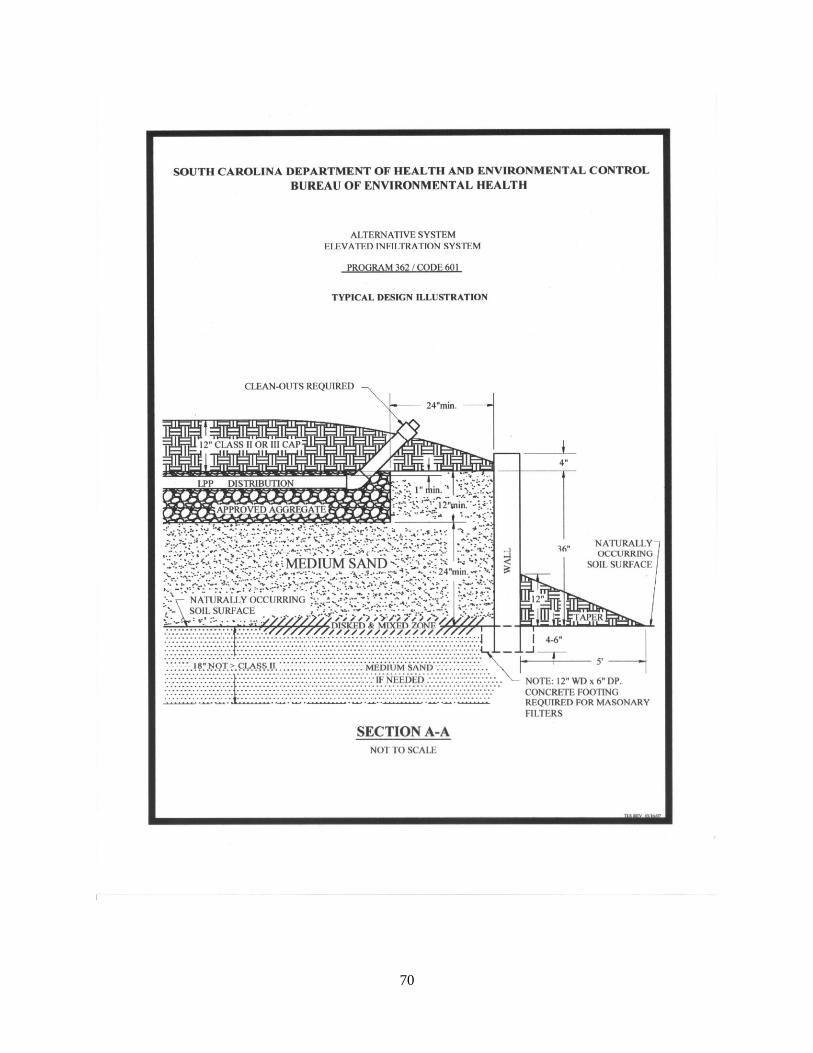
70
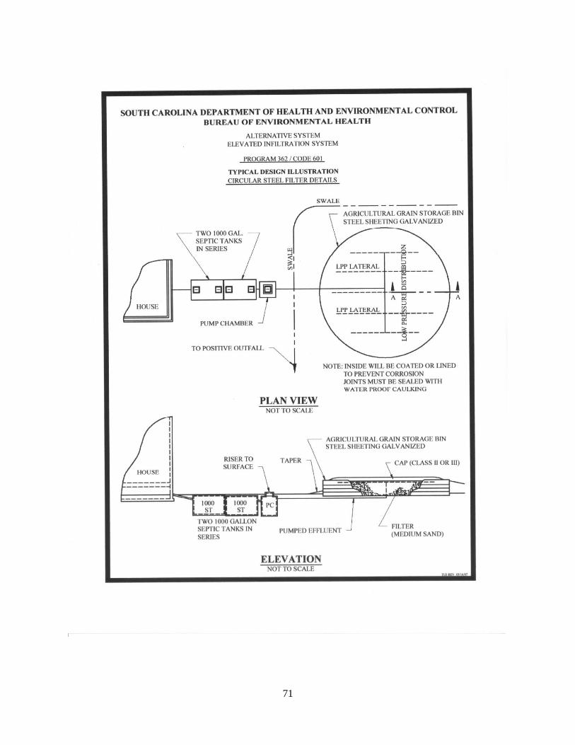
71

72

73
74
415 APPENDIX O - SYSTEM STANDARD 610 – SPECIALIZED ONSITE WASTEWATER
SYSTEM DESIGNS (LESS THAN 1500 GPD)
(1) This Standard shall not apply to the following:
(a) Projects where two or more pieces of deeded property will share a common system.
(b) Residential or commercial projects where the individual or combined peak sewage flow
is estimated to be in excess of fifteen hundred (1500) gpd.
(c) Projects that discharge wastes containing high amounts of fats, grease and oil, including
restaurants and other food service facilities, unless the system manufacturer certifies that the
proposed system is designed to treat such high strength wastes.
(d) Industrial process wastewater.
(2) A site may be considered for a specialized onsite wastewater system design if written
documentation provided by a Professional Engineer licensed in the State of South Carolina,
including soil studies performed by a Professional Soil Classifier licensed in the State of South
Carolina, indicates that the proposed system will function satisfactorily and in accordance with
all requirements of R.61-56. Such substantiating documentation must include the following:
(a) A Soils Report from a Professional Soil Classifier licensed in the State of South
Carolina including detailed soil profile descriptions and Soil Series classification(s) utilizing
methods and terminology specified in the Field Book for Describing and Sampling Soils; depth
to the zone of saturation utilizing methods and terminology outlined in Redoximorphic Features
for Identifying Aquic Conditions, and other appropriate principles specified in Soil Taxonomy;
the depth to restrictive horizons; and a description of topography and other pertinent land
features.
(b) Delineation of any affected jurisdictional wetlands, if applicable. Should any part of the
proposed onsite wastewater system be located in jurisdictional wetlands, approval from the
appropriate permitting agency(s) {i.e., US Army Corps of Engineers, SCDHEC Ocean and
Coastal Resource Management} shall accompany the application for a specialized onsite
wastewater system design.
(c) There shall be a replacement area equivalent to at least fifty (50) percent in size of the
original system area held in reserve for system repair. This area shall have a suitable
configuration, and shall meet the minimum soil and site conditions of R.61-56.
(d) A plan that has been sealed, signed and dated by a Professional Engineer licensed in the
State of South Carolina certifying that the proposed onsite wastewater system has been designed
in accordance with the requirements of R.61-56 and will function satisfactorily. The plan should
also show an area equivalent to at least fifty (50) percent in size of the original system held in
reserve for system repair.
75
(e) The manufacturer’s recommendations for operation and maintenance of the system, and
the consulting engineer’s management plan to meet this.
(3) Any Permit To Construct that is issued pursuant to this standard shall be based upon the
consulting engineer’s design, certification and other supporting documentation provided by the
Professional Soil Classifier.
(4) The consulting engineer shall be responsible for supervising construction of the system
and providing the Department with a certified “as built” plan of the actual installation. Any Final
Approval that is released pursuant to this standard shall be based upon this engineering
certification.
416 APPENDIX P - CURTAIN DRAIN STANDARD
416.1 MINIMUM CONSTRUCTION REQUIREMENTS
(1) Only pipe having received written approval from the Department may be utilized in
curtain drains. This approval shall be based upon the pipe meeting all applicable ASTM
standards.
(2) The aggregate used in curtain drains shall be a material approved by the Department and
shall range in size from one-half (½) inch to two and one-half (2 ½) inches. Fines are prohibited.
(3) The curtain drain trench shall be at least six (6) inches wide.
(4) The curtain drain shall be placed ten (10) feet upslope and twenty-five (25) feet down
slope of a subsurface wastewater infiltration area or repair area. Where the aggregate portion of
the curtain is installed at the same or lower (down slope) elevation relative to an adjacent
subsurface wastewater infiltration area or repair area, the aggregate portion of the curtain must
be a minimum of twenty-five (25) feet from adjacent the subsurface wastewater infiltration area
or repair area.
(5) The trench bottom shall have a uniform slope to the discharge point. A minimum one (1)
percent fall (12 inches per 100 feet) shall be utilized. Trench excavation with a ditch witch is
permissible provided the trench bottom has a uniform down slope gradient.
(6) The solid discharge (non-aggregate) line shall be fifteen (15) feet from adjacent
subsurface wastewater infiltration area or repair area.
(7) The down slope side of the trench toward the subsurface wastewater infiltration area shall
have a minimum six (6) mil poly or an equivalent strong, treated impervious material draped
from the trench surface to the trench bottom to prevent groundwater from bridging the curtain
drain.

76
(8) Agricultural drainpipe (slitted) with a minimum diameter of four (4) inches shall be placed
along the trench bottom in the aggregate portion. Perforated pipe is acceptable, provided the
perforations are installed facing either sideways or upward.
(9) There shall be at least two (2) inches of aggregate beneath the drainpipe.
(10) The aggregate shall be brought to at least six (6) inches from the ground surface.
(11) The aggregate shall be covered with a strong, untreated pervious material to prevent
infiltration of back fill material.
(12) Solid drainpipe with a minimum diameter of four (4) inches shall be placed along the
trench bottom from the aggregate to the discharge point.
(13) The curtain drain must discharge to the ground surface past the last wastewater infiltration
trench line.
(14) Rodent barriers on discharge pipe outlet(s) are required.
(15) If the curtain drain’s trench bottom depth exceeds thirty (30) inches, it shall be inspected
prior to the aggregate being installed to insure proper trench depth and grade. It is acceptable to
place the pipe and aggregate in the trench prior to the final inspection when a probe rod can be
used to accurately measure trench bottom depth.

77

78
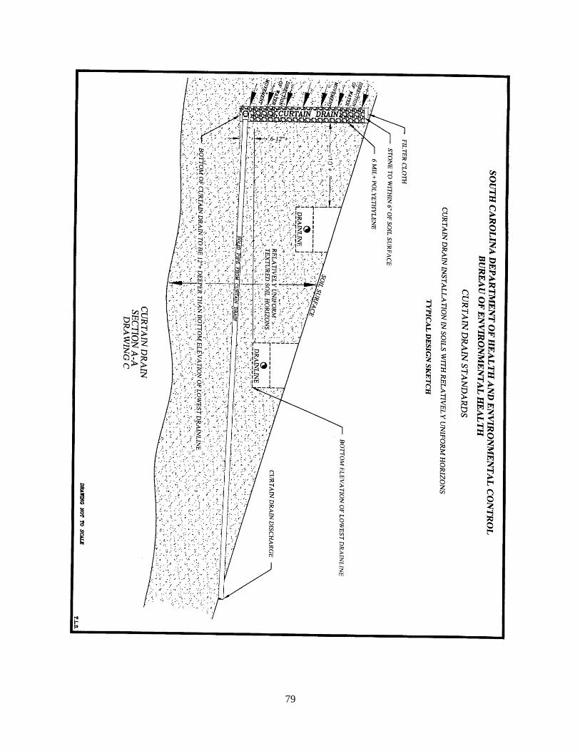
79

80
500 APPENDIX Q - LONG-TERM ACCEPTANCE RATE STANDARD FOR ONSITE
WASTEWATER SYSTEMS
USDA-NRCS
SOIL TEXTURE
SOIL CHARACTERISTICS WHEN MOIST
(FIELD TEST)
LONG-TERM
ACCEPTANCE RATE
(GPD/SF)
Sand (S) Sandy has a gritty feel, does not stain the fingers, and does
not form ribbon or ball when wet or moist.
0.9 – 1.0
Class I
Loamy Sand
(LS)
Loamy sand has a gritty feel, stains the fingers, forms a
weak ball, and cannot be handled without breaking.
Sandy Loam
(SL)
Sandy loam has a gritty feel and forms a ball that can be
picked up with the fingers and handled with care without
breaking.
0.7 – 0.8
Class II
Loam
(L)
Loam may have a slightly gritty feel but does not show a
fingerprint, and forms only short ribbons of from 0.25 –
0.50 inch. Loam will form a ball that can be handled
without breaking.
Sandy Clay Loam
(SCL)
Sandy clay loam has a gritty feel but contains enough clay
to form a firm ball, and may ribbon from 0.75 – 1.0 inch.
0.5 – 0.6
Class III
Clay Loam
(CL)
Clay loam is sticky when moist, forms a ribbon of 1.0 – 2.0
inches, and produces a slight sheen when rubbed with the
thumbnail. Clay loam produces a nondistinct fingerprint.
Silt Loam
(SiL)
Silt loam has a floury feel when moist and will show a
fingerprint, but will not ribbon and forms only a weak ball.
Silty Clay Loam
(SiCL)
Silty clay loam has a slight floury feel, is sticky when
moist, and will ribbon from 1.0 – 2.0 inches. Rubbing with
thumbnail produces a moderate sheen. Silty clay loam
produces a distinct fingerprint.
0.1 – 0.4
Class IV
Sandy Clay
(SC)
Sandy clay is plastic, gritty, and sticky when moist, forms
a firm ball, and produces a ribbon in excess of 2.0 inches.
Clay
( C )
Clay is both sticky and plastic when moist, produces a
ribbon in excess of 2.0 inches, produces a high sheen when
rubbed with the thumbnail, and forms a strong ball
resistant to breaking.
Silty Clay
(SiC)
Silty clay has a slight floury feel, is both sticky and plastic
when moist, forms a ball, and produces a ribbon in excess
of 2.0 inches.
(1) The long-term acceptance rate for system sizing shall be based upon the most
hydraulically limiting naturally occurring soil texture from the ground surface to twelve (12)
inches below the bottom of the proposed wastewater infiltration trenches. Alternative and
experimental systems installed beneath expansive soils shall be sized at a long-term acceptance
rate not to exceed 0.2-0.25 GPD/SF as specified in approved standards.

81
(2) Soil texture shall be estimated by field testing as described above. Laboratory
determination of soil texture may be substituted for field testing when conducted in accordance
with: (1) Bouyoucos, G.J. 1962. Hydrometer Method Improved for Making Particle Size
Analyses of Soils. Agron. J. 53:464-465; (2) ASTM D-422 Procedures for Sieve and Hydrometer
Analyses; or (3) the Pipette Method (ASA-CSSA-SSSA), USDA Methods of Soils Analysis, Soil
Survey Laboratory Information Manual, and Soil Survey Laboratory Methods Manual.
(3) The total linear feet (LF) for conventional onsite wastewater systems shall be calculated
by dividing the peak daily flow (GPD) by the long-term acceptance rate (GPD/SF) and dividing
the result by the trench width (FT): LF = GPD GPD/SF FT. The total linear feet for
alternative systems may either be increased or decreased in accordance with factors specified in
alternative standards.
501 APPENDIX R - PEAK SEWAGE FLOW RATE STANDARD
ESTABLISHMENT UNIT PEAK FLOW RATE
GAL/UNIT/DAY
Airport (Not Including Food Service) Passenger 3
Assembly Halls Person 3
Bar (Not Including Food Service) Customer
Seat
5
15
Beauty/Style Shops/Barber Shops Chair 100
Businesses/Offices/Factories
(Add for Showers)
Employee/Shift
Transient Employee
(4 hrs or Less/Shift)
Employee
15
10
10
Camps (No Laundry)
-Labor/Summer/Retreat
(Separate Food Service)
(Separate Bath House)
-Day Camps (with meal)
(without meal)
Person
Person
Person
Person
Person
35
10
25
15
10
Campgrounds (No Laundry)
-Full Water/Sewer
-No Sewer Risers, Bathhouse only
(Add for Dump Station)
Campsite
Campsite
Campsite
120
50
40
Car Wash (Non-automatic) Bay 500
Church (No Daycare)
-With Kitchen
-Without Kitchen
-Family Life Center
Seat
Seat
Person
3
2
5
Day Care Child 10

82
Food Service
-Full Service Utensils
-Paper/Plastic Utensils
Meal
Person
Seat
4
10
40
Reduce by 50 percent
Golf Course Club House
(Not Including Foodservice)
Player 10
Kennel Run 25
Laundromat Machine 500
ESTABLISHMENT UNIT PEAK FLOW RATE
GAL/UNIT/DAY
Mortuary Body 25
Motel (Not Including Food Service) Room 100
Picnic Park Visitor 10
Public Restroom User 3
Residential
(i.e., Apartment/Condominium/Individual
Dwelling, including Resort Rental and
Resort Residence)
Bedroom
120
Residential Care Resident 100
School
-With Cafeteria, Gym &
Showers
-With Cafeteria only
-Without Cafeteria, Gym or
Showers
-Boarding School
Student
Student
Student
Person
15
10
8
60
Stadium (Not Including Food Service)
Seat/Occupancy
3
Swimming Area Bathhouse Person 10
Visitor Center Visitor 5
The peak flow rate (GPD) for non-residential facilities may either be increased or reduced when
comparable peak water consumption data for similar establishments in similar locations vary
from the requirement. When considering such data, at least twelve (12) consecutive months
must be presented with the maximum month of consumption and the days of operation per
month being utilized to arrive at the peak flow rate (GPD).
600 APPENDIX S - ONSITE WASTEWATER PUMP SYSTEM STANDARD
600.1 PUMP TANK (GENERAL)
83
(1) The submersible sewage effluent pump(s) must be housed in a properly vented, watertight
tank that is readily accessible from the surface.
(2) A watertight access opening with removable lid shall be provided, and shall be designed
and maintained to prevent surface water inflow. Risers and other pump tank sections, where
present, shall be joined using mastic, butyl rubber, or other pliable sealant that is waterproof,
corrosion-resistant, and approved for use in septic tanks.
(3) When the pump tank must be located in an area characterized by a shallow zone of
seasonal saturation, the Department may require the use of a pre-cast manhole, a fiberglass or
polyethylene basin, or any other acceptable method for preventing groundwater intrusion.
(4) When the pump tank must be located in an area that is environmentally sensitive or
subject to flooding, applicable portions of R. 61-67, Standards for Wastewater Facility
Construction, shall apply.
(5) The pump tank shall have sufficient capacity to accommodate all level control and alarm
switches; to keep the pump(s) totally submersed in liquid at all times; and to provide the required
dosing volume and minimum pump run time. It is strongly recommended that pump tank
capacities be as large as possible (i.e., 500-1000 gal.) in order to provide emergency storage in
the event of pump or power failure.
(6) Pre-engineered, manufactured packaged pump stations can be utilized in lieu of the
composite design described herein, provided the pump meets the minimum capacity
requirements of the system and no alterations are made to the pump station other than those
specifically authorized by the manufacturer.
600.2 MINIMUM PUMPING RATES (PEAK INFLOW) AND MINIMUM RUN TIMES
(1) For residential systems, the maximum daily flow entering the pump tank shall be based
upon one hundred twenty (120) gpd per bedroom. For commercial and other facilities, this
value shall be based upon the Standard for Determining Sewage Flow Rates from Commercial
and Recreational Establishments.
(2) The minimum pumping rate (peak inflow) for discharges up to fifteen hundred (1500) gpd
shall be determined as follows:
Maximum Estimated Minimum Pumping Rate (peak
Daily Flow (gpd)____ inflow) (gpm) ______
480 and less 10
481 - 720 15
721 - 1500 20
(3) The minimum pumping rate (peak inflow) for discharges in excess of fifteen hundred
(1500) gpd shall be determined by multiplying the average flow rate (gpm) times a peaking
84
factor of not less than 2.5, where the average flow rate is based upon actual minutes per day of
facility operation.
(4) The minimum pump run time for all pump systems shall be determined as follows:
Minimum Pumping Rate Minimum Pump Run time
(peak inflow) (gpm)__ (min)___________
10 - 14 3
15 - 24 4
25 and above 5
600.3 MINIMUM DOSING VOLUME, SCOURING VELOCITY, AND PUMP CAPACITY
(1) The minimum dosing volume (gal) shall be determined by multiplying the minimum
pumping rate (gpm) times the minimum pump run time (min).
(2) The selected pump(s) must have the capacity to deliver the minimum pumping rate (gpm)
at a scouring velocity of at least one (1) ft/sec (effluent) or two (2) ft/sec (raw) against the total
dynamic head of the system. This minimum pump capacity (gpm at total feet of dynamic head)
shall be specified on SCDHEC Form 1739.
(3) Duplex pumps shall be required when the maximum estimated daily flow is equal to or
greater than fifteen hundred (1500) gallons, and each pump shall meet the minimum capacity as
stated above.
(4) In those cases where the minimum pump capacity or any other system requirements
exceed what can be specified thru the use of this Standard, the Department shall require the
applicant to retain the services of a Registered Professional Engineer.
600.4 FORCE MAIN, VALVES, AND FITTINGS
(1) The force main shall be Schedule 40 PVC, and the diameter shall be sufficient to provide a
velocity of at least one (1) ft/sec (effluent) or two (2) ft/sec (raw) using a C Factor of 150
(effluent) or 140 (raw) at the minimum pumping rate (peak inflow). The force main shall be
installed a minimum of eight (8) inches below the ground surface. Fittings and valves shall be of
compatible corrosion resistant material.
(2) A threaded union, flange, or similar disconnect device shall be provided in each pump
discharge line. The pump(s) shall be easily removable at ground surface without requiring
entrance into the tank. Valves shall also be readily accessible from the ground surface. Duplex
pump systems shall be equipped with a separate pit or box for the placement and operation of
valves.
(3) A shutoff valve (eg., gate valve) and a check valve shall be located on the discharge line
from each pump. The check valve shall be placed between the pump and the shutoff valve.
85
(4) A three-sixteenths (3/16) inch anti-siphon hole(s) shall be placed between the pump(s) and
the check valve(s) when the discharge elevation of the distribution system is below the inlet to
the pump tank.
(5) In cases where the force main must be installed over undulating terrain, automatic air
relief valves shall be placed at high points in the line to prevent air locking.
(6) The force main effluent shall discharge into a separate discharge box or distribution
manifold before entering either a septic tank or a soil wastewater infiltration trench. The flow
shall be directed to the bottom of the box thru a PVC elbow, or into a distribution manifold at an
angle of ninety (90) degrees to the septic tank or first wastewater infiltration trench.
600.5 Pumps, Control Devices and Electrical Connections
(1) Pumps shall be listed by Underwriter’s Laboratory or an equivalent third party testing and
listing agency, and shall be specifically manufactured for use with domestic wastewater.
(2) Sealed mercury control floats or similar devices designed for detecting liquid levels in
septic tank effluent shall be provided to control pump cycles. A separate level sensing device
shall be provided to activate an audible and visible high water alarm. Pump-off levels shall be
set to keep the pump submerged at all times.
(3) Pump and control circuits shall be provided with manual circuit disconnects within a
watertight, corrosion resistant, outside enclosure (NEMA 4X or equivalent) adjacent to the pump
tank, securely mounted at least twelve (12) in. above finished grade, unless installed within a
weather-tight building. Alarm circuits shall be supplied ahead of any pump overload or short
circuit protective devices. The pump(s) shall be manually operable without requiring special
tools or entrance into the tank for testing purposes. Conductors shall be conveyed to the
disconnect enclosure through water proof, gas proof, and corrosion resistant conduit(s), with no
splices or junction boxes provided inside the tank. Wire grips, duct seal, or other suitable
material shall be used to seal around wire and wire conduit openings inside the pump tank and
disconnect enclosure.
(4) For systems requiring duplex pumps, each pump shall operate in a lead-lag sequence and
be on an alternating cycle. A control panel shall be provided which shall include short circuit
protection for each pump and for the control system, independent disconnects, automatic pump
sequencer, hands-off-automatic (H-O-A) switches, run lights, and elapsed time counters for each
pump.
600.6 FINAL INSPECTION AND APPROVAL
(1) Before or during final inspection, the property owner or agent shall provide literature,
including a pump curve, describing the specific pump installed. The inspector shall evaluate the
system in accordance with this Standard, and shall confirm that all items, including the minimum
pump capacity specified on SCDHEC Form 1739, have been satisfied.

86
(2) Prior to final approval, the installer or electrician shall provide the Department with
written documentation verifying that pump system electrical connections were made in
accordance with all applicable codes. The Department may require testing of the pump system,
demonstration of watertight integrity, or any other procedure deemed necessary to confirm the
acceptability of the installation.
600.7 Raw Sewage Pump Stations
(1) In those cases where it is necessary to pump raw sewage from a residence or facility to an
onsite wastewater system, the pump station shall meet all applicable portions of this Standard
and R. 61-67, Standards for Wastewater Facility Construction.
(2) Adherence to the pump manufacturer’s recommendations shall also be a major
consideration with such systems.
700 APPENDIX T - MINIMUM DESIGN STANDARDS FOR TANK CONSTRUCTION
700.1 INTRODUCTION
The following standards describing tank designs intended to be utilized for septic tanks, grease
traps, or pump chambers for onsite wastewater disposal systems have been adopted in an effort
to assure a quality product of sufficient strength and resistance, capable of fulfilling its intended
purpose.
700.2 DESIGN APPROVAL
(1) No person shall manufacture tanks intended to be utilized for septic tanks, grease traps, or
pump chambers for onsite wastewater disposal systems without receiving approval from the
Department. All manufactured tanks must receive approval of design and reinforcement methods
prior to manufacturing.
(2) Any person desiring to manufacture tanks shall make written application on forms
provided by the Department. Such application shall include the name and address, the location of
the facility, tank capacity and design information.
(3) Prior to approval, the Department shall review the tank design, reinforcement and
manufacturing methods to determine compliance.
(4) The Department shall approve plans for manufactured tanks to insure compliance with the
South Carolina Minimum Design Standards for Tank Construction.
(5) The Department shall approve plans for fabricated tanks, other than those for precast
reinforced concrete tanks, on an individual basis. Fabricated tanks shall meet the requirements of
precast reinforced concrete tanks to provide equivalent effectiveness.
87
(6) The Department shall issue an approval to the tank manufacturer if the tank design,
reinforcement and manufacturing method complies with the South Carolina Minimum Design
Standards for Tank Construction. Tank manufacturing approvals are not transferable. When a
change of ownership occurs, the new owner shall make written application on forms provided by
the Department.
(7) The Department shall revoke approval to manufacture tanks for onsite wastewater
disposal systems if the tank manufacturer fails to comply with the South Carolina Minimum
Design Standards for Tank Construction.
700.3 GENERAL
(1) Septic tanks and grease traps shall be manufactured as single compartment or partitioned
tanks.
(2) If septic tanks and grease traps are manufactured with a partition so that the tank contains
two (2) compartments, the inlet compartment of the tank shall contain two-thirds (2/3) of the
overall capacity and the outlet compartment shall contain one-third (1/3) of the overall capacity.
The top of the partition shall terminate two inches below the bottom side of the tank top in order
to leave space for air or gas passage between compartments. The top and bottom halves of the
partition shall be constructed in such manner as to leave a four (4) inch water passage at the
vertical mid point of the partition wall for the full width of the tank.
(3) The minimum liquid capacity requirements shall be met by the use of a single septic tank
or two or more tanks installed in series. Septic tanks joined in series shall be interconnected by
an upper effluent pipe(s) with a minimum diameter of four (4) inches and a lower sludge pipe(s)
with a minimum diameter of twelve (12) inches. The upper connection(s) shall be installed level
from tank to tank, and the lower sludge pipe connection(s) shall be installed level and shall be
placed twelve (12) inches above the bottoms of the tanks. The lower sludge pipe connection(s)
can be eliminated if the first tank in series contains at least two-thirds of the total required liquid
capacity. There shall be no more than two (2) inches of fall from the inlet invert of the first tank
to the outlet invert of the last tank in series.
(4) It is required that all pump chambers function as a single compartment tank. If a two (2)
compartment tank is used, at least two (2) six (6) inch diameter holes or equivalent, must be
provided in the partition wall six (6) inches from the tank bottom.
(5) The septic tank and grease trap tank length shall be at least two (2) but not more than three
(3) times the width.
(6) The liquid depth shall not be less than four (4) feet.
(7) A minimum of nine (9) inches of freeboard shall be provided in all tanks, unless otherwise
approved by the Department.

88
(8) Useable liquid capacity for septic tanks or grease traps shall not be less than one thousand
(1000) gallons.
(9) The pump tank shall have sufficient capacity to accommodate all level control and alarm
switches; to keep the pump(s) totally submersed in liquid at all times; and to provide the required
dosing volume and minimum pump run time. It is strongly recommended that pump tank
capacities be as large as possible in order to provide emergency storage in the event of pump or
power failure.
(10) There shall be a minimum of two (2) openings in the tank wall, located at inlet and outlet
ends of the tank. The knockouts for the inlet and outlet openings of pre-cast tanks shall have a
concrete thickness of not less than one (1) inch in the tank wall. The openings shall allow for a
minimum of four (4) inch pipe or a maximum of six (6) inch pipe. No openings shall be
permitted below the tank liquid level.
(11) The inlet and outlet for septic tanks and grease traps shall be a cast-in-place concrete tee,
a polyvinyl chloride (PVC) tee, or a polyethylene (PE) tee, made of not less than Schedule 40
pipe or equivalent fittings and material. The cast-in-place concrete tees shall have a minimum
thickness of not less than two (2) inches. The invert of the outlet shall be at least two (2) inches
lower in elevation than the invert of the inlet. The inlet and outlet tees shall extend above liquid
depth to approximately one (1) inch from the top of the tank to allow venting between tank
compartments and multiple tank configurations.
(12) The inlet tee for septic tanks and grease traps shall extend sixteen (16) inches below the
liquid level.
(13) The outlet tee for a septic tank shall extend eighteen (18) inches below the liquid level
and the outlet tee for a grease trap shall extend between six (6) and twelve (12) inches above the
tank bottom.
(14) The inlet, outlet and wiring conduit openings of all tanks must utilize a resilient,
watertight, non-corrosive connective sleeve. The use of grout is prohibited.
(15) Access to each tank or compartment shall be provided by an opening located above the
inlet and outlet with an inside dimension of at least eighteen (18) inches square (18 x 18) or in
diameter, with removable tank access lids.
(16) Concrete tank access lids shall be equipped with steel lift rings at least three-eighths (3/8)
inch diameter, or by an alternative method approved by the Department.
(17) Should risers or manholes be utilized to allow access into septic tanks, grease traps or
pump chambers, the risers/manholes cover shall be constructed to prevent the release of odors,
entry of vectors and water. Grade level riser/manhole covers shall be secured by bolts or locking
mechanisms, or have sufficient weight to prevent unauthorized access. The ground shall slope
away from any access extended to grade level.

89
(18) Risers/manholes shall be sealed to the tank by using bituminous mastic, butyl rubber, or
other pliable sealant that is waterproof, corrosion-resistant, and approved for use in tank
construction. The sealant shall have a minimum size of one (1) inch diameter or equivalent. The
joint shall be smooth, intact, and free of all deleterious substances before sealing.
(19) After curing, all multi-piece tanks shall be joined and sealed at the joints by using a
bituminous mastic, butyl rubber, or other pliable sealant that is waterproof, corrosion-resistant,
and approved for use in tank construction. The sealant shall have a minimum size of one (1) inch
diameter or equivalent. The joint shall be smooth, intact, and free of all deleterious substances
before sealing. The use of grout is prohibited.
(20) All tanks must pass the ASTM C–1227 Standard for watertight testing. The Department
will choose tanks at random for testing. Tanks will be approved for use in South Carolina after
the Department ascertains that the standard is met. After joining, tanks manufactured in multiple
sections shall be plastered along the section joints with hydraulic cement or other waterproofing
sealant. Other methods of waterproofing tanks may be used as specifically approved in the plans
and specifications for the tank. Prior to backfilling, the local health department shall make a
finding that multiple section tanks are watertight if a soil wetness condition is present within five
feet of the elevation of the top of the tank. Any tank found to be improperly sealed, having
cracks or holes, which will allow for water infiltration or discharge of sewage from the tank
bottom, walls or top, will not be approved for use.
(21) Tank manufacturers must have equipment and capabilities for portion control to maintain
constant mixture formulation ratios and provide for systematic inspection of finished products to
insure compliance with the minimum tank construction and design standards.
(22) The concrete mix used for concrete tank components must be formulated to yield a
minimum twenty-eight (28) day compressive strength of four thousand (4,000) pounds per
square inch (psi).
(23) The aggregate size utilized in the concrete mix shall not exceed one-third (1/3) of the wall
thickness. Suitable aggregates include sand particle sizes from a fine to one-fourth (1/4) inch
gravel or crushed stone. Granite dust or fine screenings from a crusher operation may be used in
lieu of sand.
(24) An identifying seal must be cast or permanently affixed by an approved method from the
Department on the outlet tank wall within six (6) inches of the top. The identifying seal shall
identify the manufacturer and the liquid capacity of the tank. The tank’s cast date shall be located
on the identifying seal or imprinted on the top of the tank within six (6) inches from outlet tank
wall near the identifying seal. The lettering on the identifying seal or date imprinted on the top of
the tank shall be no more than six (6) inches in height.
(25) The tank manufacturer shall guarantee all tanks in writing for two (2) years against failure
due to poor workmanship and materials.
90
(26) Changes in approved tank design, construction, and alternative reinforcing methods will
not be allowed without prior approval from the Department.
700.4 PRE-CAST CONCRETE NON-FIBER REINFORCED SEPTIC TANKS AND GREASE
TRAPS
(1) The tank walls and bottom shall be reinforced with six inch by six inch (6 x 6) ten (10)
gauge wire mesh.
(2) Tank tops shall be reinforced with six by six inch (6 x 6) ten (10) gauge wire mesh, a
minimum of five (5) sections of three-eighths (3/8) inch diameter steel reinforcing bars oriented
perpendicular to the tank sidewalls beginning at the center spaced twelve (12) inches apart, and
four (4) sections of three-eighths (3/8) inch diameter steel reinforcing bars placed diagonally
from the corners to the center of the tank. The length of the perpendicular reinforcing bars shall
be of sufficient length to extend two (2) inches into the sidewall. The length of the four (4)
diagonal steel reinforcing bars shall be of sufficient length to extend two (2) inches into the
sidewall and six (6) inches beyond the closest perpendicular steel reinforcing bar.
(3) If a septic tank or grease trap is manufactured with a partition, the tank partition (both
halves) shall be reinforced with six by six inch (6 x 6) ten (10) gauge wire mesh. The reinforcing
wire shall be bent to form an angle of ninety (90) degrees on the ends in order to form a leg not
less than four (4) inches long. When the wire is placed in the mold the four-inch legs shall lay
parallel with the sidewall wire and adjacent to it.
(4) The tank walls and bottom thickness shall be at least two and one-half (2½) inches, and
top thickness shall be at least three (3) inches.
(5) All reinforcing wire and rods must be covered by at least one-half (1/2) inch of concrete.
(6) An acceptable vibration method shall be employed in the construction of the tank to
prevent voids in the tank walls, bottom and top.
700.5 PRE-CAST CONCRETE FIBER REINFORCED SEPTIC TANKS AND GREASE
TRAPS
(1) Tank tops shall be reinforced with a minimum of five (5) sections of three-eighths (3/8)
inch diameter steel reinforcing bars oriented perpendicular to the tank sidewalls beginning at the
center spaced twelve (12) inches apart, and four (4) sections of three-eighths (3/8) inch diameter
steel reinforcing bars placed diagonally from the corners to the center of the tank. The length of
the perpendicular reinforcing bars shall be of sufficient length to extend two (2) inches into the
sidewall. The length of the four (4) diagonal steel reinforcing bars shall be of sufficient length to
extend two (2) inches into the sidewall and six (6) inches beyond the closest perpendicular steel
reinforcing bar.
(2) Tank bottoms shall be reinforced with a minimum of seven (7) sections of three-eighths
(3/8) inch diameter steel reinforcing bars oriented perpendicular to the tank sidewalls beginning
91
at the center spaced twelve (12) inches apart. The length of the perpendicular reinforcing bars
shall be of sufficient length to extend two (2) inches into the sidewall.
(3) If a septic tank or grease trap is manufactured with a partition, the tank partition (both
halves) shall be reinforced with six by six inch (6 x 6) ten (10) gauge wire mesh. The reinforcing
wire shall be bent to form an angle of ninety (90) degrees on the ends in order to form a leg not
less than four (4) inches long. When the wire is placed in the mold the four-inch legs shall lay
parallel with the sidewall wire and adjacent to it.
(4) The tank perimeter walls shall be reinforced with three-eighths (3/8) diameter steel
reinforcing bars located one (1) inch from the tank’s top and bottom section seams.
(5) The tank walls and bottom thickness shall be at least two and one-half (2½) inches, and
top thickness shall be at least three (3) inches.
(6) All reinforcing wire and rods must be covered by at least one-half (1/2) inch of concrete.
(7) Fiber products used with this reinforcement design must be added during the mixing
process in order to achieve even distribution throughout the concrete mixture.
(8) Fiber length must range from at least one (1) to no more than two (2) inches.
(9) The fiber must be specifically manufactured for use as a concrete secondary reinforcement
and be a polypropylene fibrillated (two-dimensional fiber mesh network) material.
(10) An acceptable vibration method shall be employed in the construction of the tank to
prevent voids in the tank walls, bottom and top.
700.6 CONCRETE BLOCK SEPTIC TANKS AND GREASE TRAPS
(1) The tank walls and partition thickness shall be at least eight (8) inches and the top cover
slabs thickness shall be at least four (4) inches.
(2) The tank bottom shall be a single pour concrete slab to a depth of at least four (4) inches
within the first block course.
(3) If a septic tank or grease trap is manufactured with a partition, the tank walls and partition
shall be constructed of solid sixteen inch by eight inch by eight inch (16 x 8 x 8) concrete blocks.
The use of hollow blocks is prohibited.
(4) All joints between concrete blocks shall be mortared using masonry cement mortar or
equivalent. The joints shall have a nominal thickness of three-eighths (3/8) inch.
(5) The upper partition wall may be supported by the use of two inch by four inch by eight (2
x 4 x 8) inch bricks (or equivalent support material) standing on edge located at the block seams
of the upper partition wall.
92
(6) The top cover slabs shall be constructed such that the individual slabs will not exceed two
(2) feet in width and the length will be sufficient to extend to the outside tank width with a
minimum slab thickness of four (4) inches.
(7) The individual top cover slabs shall be reinforced with a minimum of two (2) sections of
three-eighths (3/8) inch diameter steel reinforcing bars oriented perpendicular to the tank
sidewalls spaced twelve (12) inches apart from the center. The length of the perpendicular
reinforcing bars shall be of sufficient length to extend the full length of the slab.
(8) The end cover slabs shall be constructed such that the individual slabs will not exceed
three (3) feet in width and the length will be sufficient to extend to the outside tank width with a
minimum slab thickness of four (4) inches.
(9) The end cover slabs shall be cast to allow access to each tank or compartment by
providing an opening located above the inlet and outlet tee with an inside dimension of eighteen
(18) inches square (18 x 18) or in diameter with removable tank access lids.
(10) The individual end cover slabs shall be reinforced with two (2) sections of three-eighths
(3/8) inch diameter steel reinforcing bars oriented perpendicular to the tank sidewalls spaced
twelve (12) inches apart from the center and two (2) sections of three-eighths (3/8) inch diameter
steel reinforcing bars oriented perpendicular to the tank sidewalls spaced sixteen (16) inches
apart from the center. The length of the perpendicular reinforcing bars shall be of sufficient
length to extend the full length of the slab.
(11) The top and end cover slab seams shall be sealed to the tank walls and at all joints by
using a bituminous mastic, butyl rubber, or other pliable sealant that is waterproof, corrosion-
resistant, and approved for use in septic tanks. The sealant shall have a minimum size of one (1)
inch diameter or equivalent. The use of grout is prohibited.
(12) The tank top and end cover slabs shall be equipped with steel lift handles at least one half
(1/2) inch diameter, or by an alternative method approved by the Department.
(13) All reinforcing rods must be covered by at least one-half (1/2) inch of concrete.
(14) The interior of the tank (walls and bottom) shall be plastered with a waterproofing cement
compound.
(15) An acceptable vibration method shall be employed in the construction of the tank to
prevent voids in the tank access lids, tank bottom, and top and end slabs.
700.7 PRE-CAST CONCRETE NON-FIBER REINFORCED PUMP CHAMBERS
(1) The tank walls and bottom shall be reinforced with six inch by six inch (6 x 6) ten (10)
gauge wire mesh.
93
(2) Tank tops shall be reinforced with six by six inch (6 x 6) ten (10) gauge wire mesh, a
minimum of five (5) sections of three-eighths (3/8) inch diameter steel reinforcing bars oriented
perpendicular to the tank sidewalls beginning at the center spaced twelve (12) inches apart, and
four (4) sections of three-eighths (3/8) inch diameter steel reinforcing bars placed diagonally
from the corners to the center of the tank. The length of the perpendicular reinforcing bars shall
be of sufficient length to extend two (2) inches into the sidewall. The length of the four (4)
diagonal steel reinforcing bars shall be of sufficient length to extend two (2) inches into the
sidewall and six (6) inches beyond the closest perpendicular steel reinforcing bar.
(3) The tank walls and bottom thickness shall be at least two and one-half (2½) inches, and
top thickness shall be at least three (3) inches.
(4) All reinforcing wire and rods must be covered by at least one-half (1/2) inch of concrete.
(5) An acceptable vibration method shall be employed in the construction of the tank to
prevent voids in the tank walls, bottom and top.
700.8 PRE-CAST CONCRETE FIBER REINFORCED PUMP CHAMBERS
(1) Tank tops shall be reinforced with a minimum of five (5) sections of three-eighths (3/8)
inch diameter steel reinforcing bars oriented perpendicular to the tank sidewalls beginning at the
center spaced twelve (12) inches apart, and four (4) sections of three-eighths (3/8) inch diameter
steel reinforcing bars placed diagonally from the corners to the center of the tank. The length of
the perpendicular reinforcing bars shall be of sufficient length to extend two (2) inches into the
sidewall. The length of the four (4) diagonal steel reinforcing bars shall be of sufficient length to
extend two (2) inches into the sidewall and six (6) inches beyond the closest perpendicular steel
reinforcing bar.
(2) Tank bottoms shall be reinforced with a minimum of seven (7) sections of three-eighths
(3/8) inch diameter steel reinforcing bars oriented perpendicular to the tank sidewalls beginning
at the center spaced twelve (12) inches apart. The length of the perpendicular reinforcing bars
shall be of sufficient length to extend two (2) inches into the sidewall.
(3) The tank perimeter walls shall be reinforced with three-eighths (3/8) inch diameter steel
reinforcing bars located one (1) inch from the tank’s top and bottom section seams.
(4) The tank walls and bottom thickness shall be at least two and one-half (2½) inches, and
top thickness shall be at least three (3) inches.
(5) All reinforcing wire and rods must be covered by at least one-half (1/2) inch of concrete.
(6) Fiber products used with this reinforcement design must be added during the mixing
process in order to achieve even distribution throughout the concrete mixture.
(7) Fiber length must range from at least one (1) to no more than two (2) inches.

94
(8) The fiber must be specifically manufactured for use as a concrete secondary reinforcement
and be a polypropylene fibrillated (two-dimensional fiber mesh network) material.
(9) An acceptable vibration method shall be employed in the construction of the tank to
prevent voids in the tank walls, bottom and top.
800 APPENDIX U - FIBERGLASS REINFORCED PLASTIC TANKS STANDARD
Standards describing fiberglass reinforced plastic septic tanks have been adopted assure a quality
product of sufficient strength and resistance, capable of fulfilling its intended purpose. Many of
these standards were derived from NBS Voluntary Product Standard PS 15-69, which covers
custom contact-molded reinforced polyester chemical resistant process equipment.
800.1 GENERAL REQUIREMNETS
The following general requirements are applicable to fiberglass reinforced plastic septic tanks as
defined herein, and approved design standards and structural properties of the same shall be not
less than those stated herein.
(1) Material
Resins and sealants used in the tank manufacturing process shall be capable of effectively
resisting corrosive influences of liquid components of sewage, gases generated by the digestion
of sewage, and soil burial. Materials used shall be formulated to withstand vibration, shock,
normal household chemicals, earth and hydrostatic pressure both when full and empty. Not less
than thirty (30) percent of the total weight of the tank shall be fiberglass reinforcement. For tanks
not exceeding fifteen hundred (1500) gallons liquid capacity, the minimum wall thickness shall
be three-sixteenths (3/16) inch, provided however, that isolated small spots may be as thin as
eighty (80) percent of the minimum.
(2) Inner Coating
Internal surfaces shall be coated with an appropriate gel coating to provide a smooth, pore-free,
watertight surface for fiberglass reinforced plastic parts.
(3) Physical Properties
Tanks shall be so constructed that all parts of the tank shall meet the following requirements:
(a) Ultimate Tensile Strength (Minimum) - 9,000 psi when tested in accordance with
ASTM D 638-7la, Standard Method of Test for Tensile Properties of Plastics.
(b) Flexural Strength (Minimum) - 16,000 psi when tested in accordance with ASTM D
790-71, Standard Method of Test for Flexural Properties of Plastics.

95
(c) Flexural Modulus of Elasticity Tangent (Minimum) - 700,000 psi when tested in
accordance with ASTM D 790-71, Standard Method of Test for Flexural Properties of Plastics.
(4) Watertight Integrity
Tanks shall be so constructed as to be watertight for the designed life of the tank. Lids or covers
shall be sufficiently tight when installed to preclude the entrance of surface or ground water into
the tank.
(5) Longevity
Proof from an independent testing laboratory shall be submitted substantiating a minimum life
expectancy of twenty years service for the intended use of the tank and appurtenant components
such as necessary sealants, connective fastenings, resins, etc.
(6) Safety
As a safety measure, provision shall be made in the construction of septic tank lids or covers to
preclude unauthorized entry or removal when the use of the tank necessitates positioning of
access openings at or above ground level.
(7) Workmanship
Tanks shall be of uniform thickness and free from defects that may affect their serviceability or
durability. Completed tanks are to present a smooth inside finish free of spills, pits, and
honeycombs. Plant quality control shall be sufficient to maintain a high degree of uniformity in
tank quality.
800.2 SPECIFIC REQUIREMENTS
Specific requirements for design and construction shall be not less than those specified herein,
and shall be in conformity with recognized National Standards for design and construction and in
accordance with this regulation.
800.3 CAPACITY AND DESIGN LIMITS
(1) Dimensions
(a) The inside length of a horizontal cylindrical tank shall be at least two (2) but not more
than three (3) times the width.
(b) The uniform liquid depth shall not be less than four (4) feet.
(c) At least fifteen (15) percent of the total volume of the tank shall be above the liquid
level.
96
(d) If tanks of other shapes are proposed, specifications must be submitted to the Division
of Onsite Wastewater Management for approval.
(2) Inlet
(a) Provisions shall be made for the building sewer to enter the center of one end of the
septic tank two (2) inches above the normal liquid level of the tank.
(b) A tee shall be constructed as an integral part of the tank to receive the building sewer, or
as an alternative, an integrally constructed baffle may be used.
(c) If baffles are used, suitable integrally fitted sleeves or collars shall be provided in the
inlet openings of the tank to provide surface areas sufficient to insure capability of watertight
bonding between the tank and the inlet sewer.
(d) If the tee or baffle is constructed of plastic material, it shall meet NSF Standard #14 for
drain, waste, and vent system application.
(e) If fiberglass reinforced plastic is used, it shall be of the same constituency as material of
which the tank is constructed.
(f) The inlet tee of baffle shall extend sixteen (16) inches below the designed liquid level
and be placed and secured in a vertical position so as to be watertight and preclude dislodgement
during installation, operation or maintenance activities.
(3) Outlet
(a) Provisions shall be made for the outlet sewer to receive the discharge from the tank by
providing an opening in the center of the end of the tank opposite the inlet, the invert elevation of
which shall be at the liquid level of the tank.
(b) A tee shall be constructed as an integral part of the tank to connect to the outlet sewer,
or as an alternative, an integrally constructed baffle may be used.
(c) If baffles are used, suitable integrally fitted sleeves or collars shall be provided in the
outlet opening of the tank to provide surface areas sufficient to insure capability of water tight
bonding between the tank and the outlet sewer.
(d) If the tee or baffle is constructed of plastic material, it shall meet NSF Standard #14 for
drain, waste, and vent system application.
(e) If fiberglass reinforced plastic is used, it shall be of the same constituency as material of
which the tank is constructed.
97
(f) The outlet tee or baffle shall extend eighteen inches below the design liquid level and be
placed and secured in a vertical position so as to be watertight and preclude dislodgement during
installation, operation or maintenance activities.
(g) A one (1) inch opening between the top of the inlet tee and top of the tank shall be
provided to permit free passage of gas back to the house vent.
(4) Access Openings
Openings in the top of the septic tank shall be provided over the inlet and outlet tees or baffles
with sufficient area to enable maintenance service to such tees or baffles.
(5) Identifying Markings
Fiberglass septic tanks shall be provided with a suitable legend, cast or stamped into the wall at
the outlet end, and within six inches of the top of the tank, identifying the manufacturer, and
indicating the liquid capacity of the tank in gallons.
900 APPENDIX V – THERMOPLASTIC TANKS STANDARD
(1) The Department shall approve plans for thermoplastic tanks on an individual basis.
(a) Thermoplastic tanks shall be certified by an accredited third-party to comply with the
most recent edition of IAPMO/ANSI Z1000 or CSA B66.
(b) The uniform liquid depth shall be at least three (3) feet.
(c) The inside length of the tank shall be at least two (2) times the inside width of the tank.
(2) If thermoplastic tanks having other dimensional characteristics are proposed,
specifications must be submitted to the Division of Onsite Wastewater Management for
approval, and the proposed design must be demonstrated to provide equivalent effectiveness for
storage and distribution to that of concrete or thermoplastic tanks described in this regulation.