regular boll buggy - crustbuster speed king inc. dealer check list pre-delivery check list after the...
TRANSCRIPT

Regular
BOLL BUGGY
OWNER'S MANUAL
605345 04-95


1
Index
Safety Precautions . . . . . . . . . . . . . . . . . . . . . . . . . . . . . . . . . . . . . . . . . . . . 2Dealer Check List . . . . . . . . . . . . . . . . . . . . . . . . . . . . . . . . . . . . . . . . . . . . 3Specifications . . . . . . . . . . . . . . . . . . . . . . . . . . . . . . . . . . . . . . . . . . . . . . . 4Assembly Instructions . . . . . . . . . . . . . . . . . . . . . . . . . . . . . . . . . . . . . . . 5-8Operation . . . . . . . . . . . . . . . . . . . . . . . . . . . . . . . . . . . . . . . . . . . . . . . . 9-10Lubrication and Maintenance . . . . . . . . . . . . . . . . . . . . . . . . . . . . . . . . . . . 10Storage . . . . . . . . . . . . . . . . . . . . . . . . . . . . . . . . . . . . . . . . . . . . . . . . . . . 11Trouble Shooting Guide . . . . . . . . . . . . . . . . . . . . . . . . . . . . . . . . . . . . . . . 11Isometrics and Parts Lists . . . . . . . . . . . . . . . . . . . . . . . . . . . . . . . . . . 12-16
Identification
Your Boll Buggy is identified by a Serial Number and Model Number. Record thesenumbers in the spaces provided in this manual and refer to them when ordering parts orrequesting service.
Serial Number Model Number
WarrantyWARRANTY: In addition to the implied warranties of fitness and of merchantability,CrustBuster/Speed King warrants new products sold by it to be free from defe cts in work ma nsh ip andmaterial for a perio d of 12 m onths, fro m the date of de livery to the first us er custo mer . W arranty onpurchased parts (cylinder and motors) will be the sam e as that o ffered b y the appro priatemanufacturer of these parts.
EXCLUSIONS: No warranty of any kind is made by CrustBuster/Speed King with regard to newproduc ts which have been subject to operation in excess of recommended capacities, misuse, abuse,negligence, or accident, or have been altered or repaired in any manner not authorized byCrustBuster/Speed King. CrustBuster/Speed King is constantly striving to improve its products.Changes in design and improvement will be made whenever CrustBuster/Speed King believes theefficiency of its produ cts will be impr oved the reby, but witho ut incurring any obligation to incorpo ratesuch impro vem ents in an y produc ts which have been shipped or are in service. No obligation ex istsfor com pensatio n of u nau thorized re pairs or m odific ations with out p rior ap prov al. An d in no even t willCrustBuster/Speed King be liable for consequential damages, such as but not limited to: downtime,delays, etc.
WARRANTY REGISTRATION: This warranty is not valid unless registered with CrustBuster/SpeedKing within 10 da ys from the date of purch ase. It is the s ole respo nsibility of the selling retail dealerto fill out the registration forms and see that they are properly filed with CrustBuster/Speed King.
WARRANTY PROCEDURE: Should any part fail to conform with this warranty, CrustBuster/SpeedKing will repair or repla ce the par t or pa rts wh ich do not confo rm. If a pa rt is de fectiv e, tak e it to yourauthorized CrustBuster Farm Equipment Dealer immediately, along with your warranty registration,and com plete the prop er form s reque sting a wa rranty adjustment. Our representative will pick up thepart to be returned to the factory for examination. If the customer (first user) requests that a new partbe substituted for the old part, a new part will be charged to the dealer who will in turn charge thecustomer. If the part is found by us to be defective, a credit for the part will be g iven to the d ealer tobe passe d on to the custom er. If the dealer or customer wishes to repair the part, this will be doneonly if authorized by CrustBuster/Speed King. This warranty procedure is in addition to all remediesauthorized by law.
CRUSTBUSTER/SPEED KING, INC.Box 1438Dodge City, KS 67801

2
SAFETY PRECAUTIONSThe following information is on the decal attached to your machine. Readand follow these instructions for your safety and the safety of anyone aroundthe machine.
CAUTION1. ALWAYS DISMOUNT FROM THE SIDE OF THE TRACTOR, NEVER AT THE REAR.2. DO NOT ALLOW PEOPLE TO RIDE ON THIS MACHINE.3. NEVER CARRY ANYONE ON THE TRACTOR.4. BE SURE EVERYONE IS CLEAR OF THE MACHINE BEFORE STARTING ENGINE OR
OPERATION.5. USE S.M.V. EMBLEM WHEN OPERATING ON HIGHWAYS, EXCEPT WHEN PROHIBITED
BY LAW.6. WHEN TRANSPORTING UNIT ON ROADS OR HIGHWAYS ALWAYS WATCH FOR WIDTH
AND OVERHEAD OBSTRUCTIONS.7. NEVER DUMP WHEN STRONG WIND BLOWS FROM RIGHT.8. ALWAYS DUMP WITH MACHINE LEVEL OR RIGHT SIDE LOWER.9. WHEN DUMPING BASKET, ALWAYS WATCH FOR OVERHEAD OBSTRUCTIONS.
10. NEVER LUBRICATE OR MAKE ADJUSTMENTS WHEN ENGINE IS RUNNING OR BASKETIS IN RAISED POSITION.
11. KNOW YOUR MACHINE, STUDY OPERATOR'S MANUAL. ASK YOUR DEALER IF YOUHAVE ANY QUESTIONS ON THE OPERATION OF THIS MACHINE.
12. USE CAUTION WHEN TURNING OR CROSSING ROUGH TERRAIN.13. USE CAUTION WHEN OPERATING AROUND ELECTRIC POWER LINES.
WARNING
DO NOT DUMP AROUND ELECTRICAL POWER LINES
ELECTROCUTION CAN RESULT
May we suggest that you take a few additionalminutes to read over more than once the areas ofthis manual where SAFETY SYMBOLS andCAUTION notes appear. These are areas wherethe operator should use particular care. Play it"SAFE." KNOW THE DANGER AREAS AND AVOID THEM.
Look for this symbol to point outimportant safety precautions. Itmeans---
ATTENTION!BECOME ALERT!
YOUR SAFETY ISINVOLVED.
3
Dealer Check List
Pre-Delivery Check List
After the Boll Buggy has been completely assembled and lubricated, inspect it thoroughly to be certainit is in good running order before delivering it to the customer. The following check list is a reminderof points to inspect. Check off each item as it is found satisfactory, or after proper adjustment is made.
Boll Buggy Inspection
______ Check all bolts and nuts to be sure they are on tight.
______ Check hydraulic system to make sure it has been purged to remove air as instructed inowner's manual.
______ Hitch adjusted to level Boll Buggy as instructed in owner's manual.
______ Check and, if necessary, lubricate all lubrication points.
______ Check to see if the Safety Decal is in place. (Refer to opposite page for decal information.)
______ Check wheel hubs for bearing preload and remove end play if necessary.
Boll Buggy Functional Test
______ Attach Boll Buggy to tractor drawbar with 2 5/16" ball hitch or 7/8" diameter hitch pin or larger.Raise basket gradually, paying particular attention to the last 8 to 10 inches of cylinder strokenot to unbalance the unit with a sudden surge of hydraulic pressure.
NOTE: Observe safety precautions on the decal and in the manual while dumping basket.WATCH FOR OVERHEAD OBSTRUCTION.
Delivery Check List
______ Explain the adjustments for implement operation.
______ Review safety precautions with the owner and operator as stated on the safety decal and inthe manual.
______ Give the customer the owner's manual and explain the importance of reading this manual.
IMPORTANT: The Warranty Registration form must be completed, signed by both dealerand customer and returned to CrustBuster/Speed King, Inc., Box 1438, Dodge City, KS67801, to validate the warranty. If warranty registration is not completed and returned, theproduct concerned will not be covered by warranty policy.

4
Boll Buggy Specifications
Capacty
Volume . . . . . . . . . . . . . . . . . . . . . . . . . . . . . . 1015 Cu. Ft.
Height
Ground to basket pivot point . . . . . . . . . . . . . 12'Ground to top panel (dump in side) . . . . . . . . 11'
. . . . . . . . . . . . . . . . . . . . . . . .Ground to bottom of main frame . . . . . . . . . . 25 "Ground to top panel (dump out side) . . . . . . . 13'6"
Basket
Length . . . . . . . . . . . . . . . . . . . . . . . . . . . . . . 14'Width at top . . . . . . . . . . . . . . . . . . . . . . . . . . 11'Width at bottom . . . . . . . . . . . . . . . . . . . . . . . 44e"
Length
Overall Length . . . . . . . . . . . . . . . . . . . . . . . . 20'Empty Weight (less tires) . . . . . . . . . . . . . . . . 5390#Tongue Jack Stand . . . . . . . . . . . . . . . . . . . . StandardWalking Beam Axles . . . . . . . . . . . . . . . . . . . 6' -10½" (Center to Center)Hydraulic Cylinders:Basket Lift . . . . . . . . . . . . . . . . . . . . . . . . . . . 4" diameter x 48" strokes
2 " Rod diameter
NOTE: Specifications are subject to change without prior notice.

5
Figure 1
Assembly Instructions
1. For assembly, select a level area withoverhead hoist capable of lifting 15 feet oran area in which a fork or snorkel lift willhave easy access.
NOTE: Refer to drawings in back of thismanual during assembly process.
2. Block main frame level approximately 2 feetoff ground. (Two feet measured to bottomside of main frame.)
CAUTION: When blocking mainframe, set blocks securely andat enough points to avoiddanger of frame falling duringassembly.
3. Locate walking beam axle pivot pins andinstall walking axles onto frame. Lift axlesup into mounting sockets on outside edgeof frame and install short pivot pin.
NOTE: Always install short pivot pin withwelded head on inside of frame and rotatepin so that extended length of pin head fitsbetween the two gussets on frame.
Inspect long center pivot pin and note drillcountersink centered between end holes.This countersink is provided so that the setscrew in center pivot mounting can bescrewed into it, thus giving apositive lock against rotation ofthe pin. Insert the center pivotpin, lock the set screw intoshaft, set jam nut, and installwashers and cotter pinsthrough shaft ends.
4. Mount tire and wheelassemblies onto hubs.
5. Blocking can now be removedfrom frame and tires set onground. Place jack on front ofunit and adjust length to levelframe.
6. Place floor panel onto mainframe with the long formed legof bottom panel located onright side on main frame. Rightside is determined by standingat rear of machine and lookingforward indirection of travel.Locate bottom panel on main
frame as shown in Figure 1. Panel must belocated for ease of assembly in lateroperations.
NOTE: All panels have loops welded onthem for use in lifting panels into placeduring the assembly process.
7. Sit lower front and rear end panels into floorpanel. Install bolts, flat washers, and nuts, butDO NOT TIGHTEN AT THIS TIME.
NOTE: The high pointed end of front andrear lower panel must be on left side of unit.See basket parts schematic for view of howlower end panels assemble.
CAUTION: Place 10 inch "C"clamps on right side as shownin Figure 1 to hold basket ontoframe during assembly.
8. Locate the lower side panel (dump out) andinstall on the left side of basket. Install thedoor panel (dump in) on the right side ofbasket.
NOTE: When installing the two lowerpanels, always locate them so that the twoinch leg angle side of panels are bolted tothe formed leg on floor panel and the endsof panel are aligned with ends of floorpanel.
6
Assembly Instructions
9. At this time, securely tighten bolts attachinglower end panels to floor panel. Thentighten bolts attaching two inch angle leg oflower side panels to floor panel. Nowtighten bolts attaching lower side panels tofront and rear end panels.
10. Locate middle panel (dump out) and installon left side of basket. Insert all bolts whichalign with mating panels and tighten.
11. Place front and rear upper panels onto
basket lower end panels between lowerpanel on right side and middle panel on theleft side. Move panel to the left on basketuntil it is against middle panel.
NOTE: When installing upper end panels,
the cylinder anchor plate must beon the outside of the basket frameand to the left side of basket.
Install all bolts in the panel, but DO NOTTIGHTEN AT THIS TIME.
12. Locate top panel (dump out) which has
main basket pivot pipe welded into frame,install on left (dump out) side of basket, andinsert all bolts loosely. Be sure to installbolts on ends of basket which attach thepivot pipe support plate to the top front andrear panels.
13. The last panel, top panel (dump in), should
be installed on right side of basket. Installall bolts loosely.
14. Install gussets across the top right side
corners. Install bolts loosely.
15. At this time, all remaining bolts on basket
should be tightened in the followingsequence:
A. Tighten bolts attaching middle left panelto top left panel.
B. Tighten bolts attaching top front andrear panels to lower front and rearpanels.
C. Tighten bolts attaching middle left andtop left panels to upper front and rearend panels.
D. Tighten 5/8" bolts attaching top leftpivot panel to upper end panels.
E. Tighten bolts attaching top right panelto door panel on right side.
F. Tighten bolts attaching top right panelto upper front and rear end panels.
G. Tighten bolts attaching gussets acrosstop right corners.
16. Locate extension panels and attach the
front and rear extensions to the top endpanels. DO NOT TIGHTEN BOLTS ATTHIS TIME. Attach the dump in sideextension and end extensions to the dumpin side top panel and to the front and rearextensions. Install the extension gussets atthe top right side of the extensions. Tightenall bolts at this time.
17. Before installing A-frames, screw grease
line into basket pivot tube at the top of A-frames. Route the grease line down theinside of the A-frames attaching to the threebolts provided. Use the 5/16" hose clampsto secure the grease lines. Attach the 1/8"pipe couplers and grease zerks to the endof the lines.
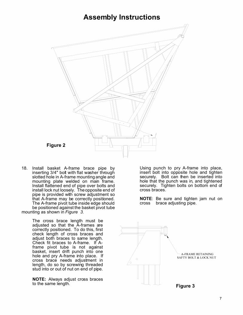
Raise A-frame (Figure 2) and slide pivottube of A-frame over the basket pivot pipe.Allow lower end of A-frame to rotatedownward onto main frame inside ofmounting plates welded on main frame.Insert bolts attaching A-frame to mainframe.
NOTE:1. It may be necessary to remove "C"
clamps from basket placed in STEP #7to install mounting bolts.
2. Install 1/2" x 3" bolts and lock nut inpipe panel as shown in Figure 3.
7
Figure 2
Figure 3
Assembly Instructions
18. Install basket A-frame brace pipe byinserting 3/4" bolt with flat washer throughslotted hole in A-frame mounting angle andmounting plate welded on main frame.Install flattened end of pipe over bolts andinstall lock nut loosely. The opposite end ofpipe is provided with screw adjustment sothat A-frame may be correctly positioned.The A-frame pivot tube inside edge shouldbe positioned against the basket pivot tube
mounting as shown in Figure 3.
The cross brace length must beadjusted so that the A-frames arecorrectly positioned. To do this, firstcheck length of cross braces andadjust both braces to same length.Check fit braces to A-frame. If A-frame pivot tube is not againstbasket, insert drift punch into onehole and pry A-frame into place. Ifcross brace needs adjustment inlength, do so by screwing threadedstud into or out of nut on end of pipe.
NOTE: Always adjust cross bracesto the same length.
Using punch to pry A-frame into place,insert bolt into opposite hole and tightensecurely. Bolt can then be inserted intohole that the punch was in, and tightenedsecurely. Tighten bolts on bottom end ofcross braces.
NOTE: Be sure and tighten jam nut oncross brace adjusting pipe.

8
Figure 4a
Figure 4b
Figure 4c
Assembly Instructions
19. Using six inch long bolts, install hitch ontoframe as shown in Figures 4a, 4b, & 4c.Several mounting holes are provided inframe so that frame may be leveled wheninstalled on different tractor drawbarheights. Notice that the clevis hitch may beinstalled in two ways giving additionaldrawbar heights.
20. Unit is now ready for installation ofhydraulic cylinders and hoses. Checkhydraulic schematic found in back ofmanual for details of where the differentcomponent parts connect. Install hydrauliccylinders in place connecting the rod end tobasket and base end to A-frame.
CAUTION: Cylinders must beinstalled so that fitting ports arefacing toward right side of machine.If placed in opposite directionfittings will be broken off whenbasket is raised.
Install 90° elbow fittings into cylinder portsand tighten until hose connecting swivel ispointing downward.
NOTE: It is recommended that teflontape be applied to fitting end which installsinto the cylinder ports. Doing so will avoidleaks but caution should be used to avoidovertightening fitting thus causing cylinderto crack.
Refer again to hydraulic schematic in backof manual and install and tighten hoses asshown. Locate one hose on each side ofbolts welded on top of frame and on insideof A-frame tube and install formed clampover bolt. Install nut and lock washer andtighten only enough to hold hose in place.
21. Unit should now be completely assembledand ready for check out, purging ofhydraulic cylinders with oil and connectionto tractor.
IMPORTANT:Do not attempt to operate this unituntil hydraulic system has beencompletely purged of air as outlined inthe operation section of manual.

9
Operation
Familiarize yourself with the various features of theBoll Buggy before operating. Read this section ofyour manual carefully.
Attaching to Tractor
1. Adjust tongue ball hitch (standard) or clevishitch (optional) to the appropriate holes on thetongue to level main frame when attached totractor drawbar.
2. Attach machine to tractor (for the standard ballhitch) using a 2 5/16" ball (minimum capacity12,500#) with enough shank and thread lengthto secure it with a full depth nut and lockwasher. Make sure the ball shank threads goall the way through the nut.
Hydraulic System Purging Procedure
Hydraulic cylinders and hoses must be run withoutload to remove all air from system.
1. Remove basket cylinder rod pins attachingupper end of cylinder to basket and block or tiein place so when rod is extended it will not hit orinterfere with any portion of the basket.
2. Install the required male quick coupler end ontohoses going to tractor and then attach hoses toa pair of quick coupler hydraulic fluid outlets onthe tractor. Check the tractor hydraulic fluid andadd fluid if system is not completely full.
3. Start tractor engine and activate valve lever toextend hydraulic cylinders approximately one-third of stroke or 16 inches. Stop at this pointand check hydraulic fluid level in tractor. Addrequired amount to bring level to full. Againextend hydraulic cylinder an additional 16inches of stroke or total of approximately 32inches. Repeat procedure above in checkingfluid level in tractor. Extend cylinders tomaximum extended position and repeatprocedure used to check fluid level.
4. With the tractor fluid at a safe operational level,fully retract and extend the cylinders severaltimes to insure removal of all air from system.
5. Retract cylinders to fully closed position andreconnect cylinder rod to basket using cylinderpin.
6. After cycling cylinders and purging lines andcylinders of any air locks, reconnect cylinders.Be certain all cylinder pins are securely held inplace and will not work out under load.
7. You are now ready to dry run the unit.Complete the lubrication of the unit as describedon page 10. Read the operating section of thismanual on pages 9 and 10 before dryrunning of unit.
CAUTION: While cycling thebasket for the first time it is best tohave an observer on the ground at asafe distance to give instructions tothe operator. The observer will belooking for any hydraulic hose pinchpoints, loose connections, any bindingof basket or anything else that wouldprohibit the safe and successfuloperation of the unit. Be sure toobserve the grease line at the mainpivot point in the upper corner forsufficient clearance.
Operating Information
Before operating this unit, refer to the Lubricationsection in this manual on page 10 and make suremachine is properly lubricated.
CAUTION: When turning or crossingrough terrain, slow tractor speed down.
CAUTION: Be sure everyone is clearof the machine before starting engine oroperation.
To dump the Boll Buggy, simply drive along side oftrailer or module and stop at the required position.Set tractor engine RPM at approximately 1/2 to 3/4maximum engine RPM. Actuate tractor valve leverto raise basket.

10
Operation
CAUTION: Use the following cautions when dumping the Boll Buggy basket:
1. Use caution when operating around powerlines.
2. Watch for overhead obstructions which mightinterfere with the basket.
3. Always select level area for dumping. If thearea is uneven, position units so when theBoll Buggy is dumping, the dump-in side ofthe unit is lower than the dumping side. Thiswill minimize the possibility of unit overturningduring dump cycle.
4. Do not move unit with basket partially up orbasket lift cylinders partially extended.Damage could result to cylinders and/orbasket frame.
5. When dumping, always note direction strongwinds are blowing from. Position units soBoll Buggy basket is dumping into windcurrent, or that wind current is blowing intoeither the front or rear of the Boll Buggy.
6. Always dismount from the side of the tractor,never at the rear.
7. Do not allow people to ride on this machine.
8. Never carry anyone on the tractor.
9. Be sure everyone is clear of the machinebefore starting engine or operation.
10. Use SMV emblem when operating onhighways except when prohibited by law.
11. When transporting unit on road or highways,always watch for width and overheadobstructions.
12. Never lubricate or make adjustments whileengine is running or basket is in raisedposition.
13. Know your machine, study this manual, askyour dealer if you have any questions on theoperation on this machine.
Lubrication and Maintenance
IMPORTANT: Before operating your Boll Buggy, make sure it is properly lubricatedand thoroughly inspected. Only a minimum of time and effort is required to regularlylubricate and maintain this machine to insure long life and trouble-free operation.
Lubrication
� Keep all lubricants and lubrication points freefrom dirt and grit.
� Use a general purpose lithium base grease tolubricate the pressure grease fittings.
� The following lubrication schedule is recommended:
Walking Beams(4-Fittings) . . . . . . . DailyBasket Pivots (2-Fittings) . . . . . . WeeklyWheel Bearings . . . . . . . . Repack Yearly
Maintenance
� Inspect your machine regularly to preventaccidents and breakdowns.
� Check hitch pin periodically for wear andreplace if worn excessively.
� Check hitch mounting bolts occasionally tomake sure they are tight.
� Check wheel spindle bearing preload aftertwenty(20) hours operation.
11
Storage
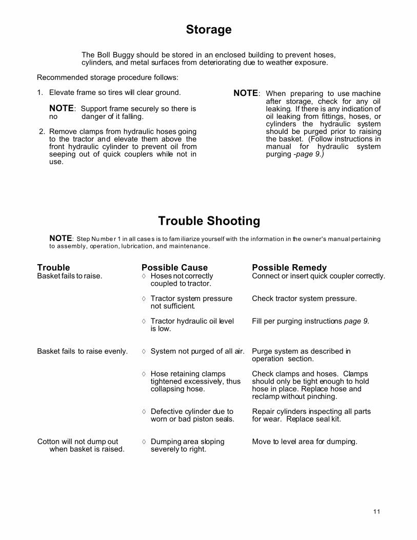
The Boll Buggy should be stored in an enclosed building to prevent hoses,cylinders, and metal surfaces from deteriorating due to weather exposure.
Recommended storage procedure follows:
1. Elevate frame so tires will clear ground.
NOTE: Support frame securely so there isno danger of it falling.
2. Remove clamps from hydraulic hoses goingto the tractor and elevate them above thefront hydraulic cylinder to prevent oil fromseeping out of quick couplers while not inuse.
NOTE: When preparing to use machineafter storage, check for any oilleaking. If there is any indication ofoil leaking from fittings, hoses, orcylinders the hydraulic systemshould be purged prior to raisingthe basket. (Follow instructions inmanual for hydraulic systempurging -page 9.)
Trouble Shooting
NOTE: Step Nu mbe r 1 in all case s is to fam iliarize yourself with the information in the owner's manual pertainingto assembly, operation, lubrication, and maintenance.
Trouble Possible Cause Possible RemedyBasket fails to raise. � Hoses not correctly Connect or insert quick coupler correctly.
coupled to tractor.
� Tractor system pressure Check tractor system pressure.not sufficient.
� Tractor hydraulic oil level Fill per purging instructions page 9.is low.
Basket fails to raise evenly. � System not purged of all air. Purge system as described in operation section.
� Hose retaining clamps Check clamps and hoses. Clamps tightened excessively, thus should only be tight enough to hold collapsing hose. hose in place. Replace hose and
reclamp without pinching.
� Defective cylinder due to Repair cylinders inspecting all parts worn or bad piston seals. for wear. Replace seal kit.
Cotton will not dump out � Dumping area sloping Move to level area for dumping.when basket is raised. severely to right.

12
Main
Fra
me
Re
pa
ir P
art
s

13
Main FrameRepair Parts
Item Qty Part No. Description1 1 945352 Main Frame2 1 954719 Ball Hitch 2 5/16"
2A 1 942813 Hitch -Clev is type (optio nal)3 1 945345 Front A-Frame4 1 945337 Rear A-Frame5 2 945394 Cross Brace E nd Adju st.6 2 945386 Cross Brace7 2 942862 Walking Beam8 1 307397 Cen ter Piv ot Pin9 2 942771 Outer Piv ot Pin
10 4 530584 Rim 15" x 10" 8- bolt11 4 603613 Dust Cap12 4 331801 Nut 7/8" Hex Slotted SAE13 4 334771 Washer 7/8" Flat SAE14 4 401687 Outer Bearing15 4 401679 Outer Cup16 4 550970 Hub w/cu ps on ly17 4 401661 Inner Cup18 4 401653 Inner Bearing19 4 401646 Grease Seal20 32 336297 Lug Bolt 9/16" x 1 1/8"21 4 02154300 Cotter Pin 5/32" x 1 1/2"22 2 847103 W alkin g Beam Ass em bly
(Includes #7, and #11 thru #21)
Item Qty Part No. Description23 6 335794 Washer 1 1/2" Flat SAE24 1 530402 Jack 2000#25 2 466953 Cylinder 4 x 48 w/2" ram26 12 01147800 HHCS 1/2" x 1 1/2"27 4 331363 Nut 1/2" Hex Nylock28 8 335836 Nut 1/2" Flange Lock29 8 330159 Washer 1/2" Flat30 2 335174 HHCS 3/4" x 2 1/2"31 2 330316 Nut 3/4" Hex Nylock32 2 330340 Washer 3/4" Flat33 2 334466 HHCS 3/4" x 6"34 2 330290 Nut 3/4" Hex35 2 330332 Washer 3/4" Lock36 9 199976 Hose C lamp37 9 330043 Washer 3/8" Lock38 9 330035 Nut 3/8" Hex39 4 335802 Cotter Pin 5/16" x 2 1/2"40 1 334367 Set Screw 1/2" x 1 3/4"41 1 332262 Nut 1/2" Hex Jam42 4 600346 Zerk 1/4"-28 x 17/32"43 2 469494 Grease line 1/8" x 112"44 2 331066 Pipe Coupler 1/8"45 2 02738300 Zerk 1/8" NPTM46 6 01059500 Hose Clamp 5/16"
14
Basket
Re
pa
ir P
art
s
15
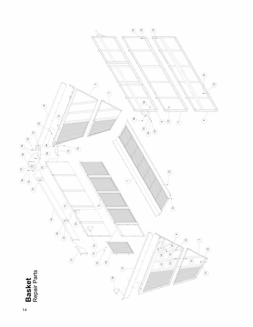
BasketRepair Parts
Item Qty Part No. Description1 1 945329 Floor Panel2 1 945253 Front Lower Panel3 1 945261 Rear Lower Panel4 1 945279 Front Top Panel5 1 945287 Rear Top Panel6 1 942599 Left Lower Panel7 1 942607 Left Mid Panel8 1 945311 Left Top Panel9 1 945501 Door Panel
10 1 945519 Door11 1 945295 Right Top Panel12 1 202143 Rear Panel Gusset13 1 202150 Front Panel Gusset14 1 254839 Rear End Extension15 1 254821 Front End Extension16 1 254797 Right Side Extension
Item Qty Part No. Description17 1 254771 Side End Extension-Front18 1 254789 Side End Extension-Rear19 1 254813 Rear Extension Gusset20 1 254805 Front Extension Gusset21 156 01180900 HHCS 1/2" x 1 1/4"22 148 330159 Washer 1/2" Flat23 156 335836 Nut 1/2" Flange Lock24 6 01071000 HHCS 5/8" x 2"25 12 330183 Washer 5/8" Flat26 6 330878 Washer 5/8" Lock27 6 330571 Nut 5/8" Hex28 2 334946 HHCS 1/2" x 3"29 2 331363 Nut 1/2" Nylock30 3 330852 Washer 5/16" Flat31 3 335984 Nut 5/16" Wing
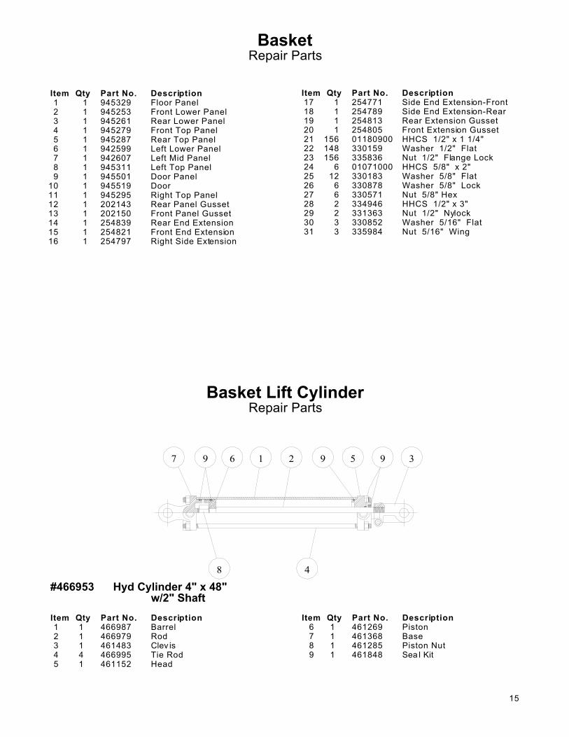
Basket Lift CylinderRepair Parts
#466953 Hyd Cylinder 4" x 48" w/2" Shaft
Item Qty Part No. Description1 1 466987 Barrel2 1 466979 Rod3 1 461483 Clev is4 4 466995 Tie Rod5 1 461152 Head
Item Qty Part No. Description6 1 461269 Piston7 1 461368 Base8 1 461285 Piston Nut9 1 461848 Sea l Kit
16
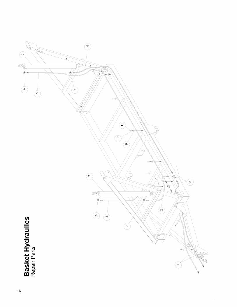
Basket
Hyd
rau
lics
Re
pa
ir P
art
s
De
sc
rip
tio
n
11
3"
3/8
MP
/ 1
/2 M
P
50
"
3/8
MP
/ 3
/8 M
P
98
"
3/8
MP
/ 3
/8 M
P2
10
"
3/8
MP
/ 3
/8 M
P
De
sc
rip
tio
n
26
0"
3/8
MP
/ 3
/8 M
P
Ad
pt
90
°
1/2
" M
P /
3/8
" F
P S
wiv
el
Cy
lind
er
4"
x 4
8"
w/2
" s
ha
ft3
/8"
FP
/
3/8
" F
P S
wiv
el (2
)
Ho
se
Cla
mp
Wa
sh
er
3/8
" L
oc
k
Nu
t 3
/8"
He
x


P.O.Box 1438 Dodge City, Kansas 67801 (316) 227-7106