register of illustration -...
TRANSCRIPT

ECSC Steel RTD Programme
project carried out with a financial grant of the European Coal and Steel Community
Composite Bridge Design for Small and Medium Spans
Design Guide
with standard solutions documented in drawings and static analysis
Contract Number: 7210-PR/113
Contractors: Institute of Steel Construction, RWTH Aachen (D) – Co-ordinator
Centre Technique Industrielle de Construction Metallique, Paris (F) Division of Steel Structures, Luleå University of Technology (S)
Service Ponts et Carpentes, Université de Liège (B) Institute for Steel and Composite Structures, BUGH Wuppertal (D)
ProfilARBED-Recherches, Esch-sur-Alzette (L)
Commencement Date: 01.07.1998 Completion Date: 31.12.2001
2002


Design Guide Composite bridge design for small and medium spans
Design Guide
Page 3
REGISTER OF ILLUSTRATION .........................................................................................5
1 INTRODUCTION ...................................................................................................... 1-1
2 COMPOSITE BRIDGE CONCEPT........................................................................... 2-2
2.1 General .............................................................................................................................................................2-2 2.1.1 ECSC-Project: Composite bridge design for small and medium spans ...................................................2-2 2.1.2 Documents ...............................................................................................................................................2-4
2.2 Boundary Conditions ......................................................................................................................................2-4 2.2.1 Assumptions.............................................................................................................................................2-4 2.2.2 Standards..................................................................................................................................................2-4
2.3 Superstructure .................................................................................................................................................2-5 2.3.1 Static system ............................................................................................................................................2-5 2.3.2 Steel construction.....................................................................................................................................2-8 2.3.3 Shear connectors ......................................................................................................................................2-9 2.3.4 Slab ..........................................................................................................................................................2-9 2.3.5 Prefabricated elements .............................................................................................................................2-9 2.3.6 Cross girder and End-cross girder..........................................................................................................2-11
2.4 Design Charts.................................................................................................................................................2-12 2.4.1 Simple bridge with end supports pinned................................................................................................2-13 2.4.2 Simple bridge with end supports clamped .............................................................................................2-16 2.4.3 Two-span bridge with end supports and the middle support pinned......................................................2-19 2.4.4 Two-span bridge with end supports clamped and the middle support pinned .......................................2-22
3 SOFTWARE ........................................................................................................... 3-25
4 ADVANCED STANDARD SOLUTIONS ................................................................ 4-28
4.1 Abutments ......................................................................................................................................................4-28 4.1.1 Abutments with expansion joints ...........................................................................................................4-28 4.1.2 Abutments without expansion joints......................................................................................................4-28 4.1.3 Prefabricated foundations ......................................................................................................................4-29 4.1.4 Integral abutments..................................................................................................................................4-30
4.2 Main Girder ...................................................................................................................................................4-32 4.2.1 Hybrid girder..........................................................................................................................................4-32 4.2.2 Studs as shear connectors.......................................................................................................................4-39 4.2.3 Dismountable shear connectors .............................................................................................................4-40 4.2.4 Bolted Connections of Girders in Span..................................................................................................4-43 4.2.5 Shear resistance of the girders ...............................................................................................................4-50 4.2.6 Lateral torsional buckling of the beams in service.................................................................................4-50 4.2.7 Detailing of the cross beams or cross braces .........................................................................................4-57
4.3 Concrete Deck................................................................................................................................................4-59 4.3.1 Joints in fully prefabricated slabs...........................................................................................................4-59 4.3.2 Concrete technology for prefabricated slabs and in situ concrete..........................................................4-61 4.3.3 Creep and shrinkage effects ...................................................................................................................4-66 4.3.4 Cracking of the joints and of the slabs ...................................................................................................4-67 4.3.5 Vibration of bridges ...............................................................................................................................4-67
4.4 Cross girder ...................................................................................................................................................4-68 4.4.1 Connection always in negative moment area.........................................................................................4-68 4.4.2 Connection in alternating moment area .................................................................................................4-68

Design Guide Composite bridge design for small and medium spans
Design Guide
Page 4
4.4.3 Static design...........................................................................................................................................4-69 4.4.4 Fatigue design [EC 3.1.1 – 6.2] .............................................................................................................4-71 4.4.5 Example .................................................................................................................................................4-71 4.4.6 Recommendations..................................................................................................................................4-73
4.5 Fabrication and Erection ..............................................................................................................................4-75 4.5.1 Girder Type Composite Bridges ............................................................................................................4-75 4.5.2 Prestressed Composite Girders ..............................................................................................................4-84 4.5.3 Lateral torsional buckling of the beams during erection........................................................................4-86
5 EXAMPLES............................................................................................................ 5-88
5.1 Composite Bridge with Partially Prefabricated Elements .........................................................................5-89 5.1.1 Static System..........................................................................................................................................5-89 5.1.2 Concrete Plate ........................................................................................................................................5-89 5.1.3 Hybrid Girder (inner beam) ...................................................................................................................5-90 5.1.4 Hybrid Girder (outer beam) ...................................................................................................................5-90 5.1.5 Shear Connectors ...................................................................................................................................5-91 5.1.6 Loads on the Structure ...........................................................................................................................5-91 5.1.7 Settings for the Calculation....................................................................................................................5-93 5.1.8 Design ..................................................................................................................................................5-105 5.1.9 Results of the Calculation (outer beam)...............................................................................................5-107 5.1.10 Design ..................................................................................................................................................5-110
5.2 Composite Bridge with Fully Prefabricated Elements .............................................................................5-112 5.2.1 Static System........................................................................................................................................5-112 5.2.2 Concrete Plate ......................................................................................................................................5-112 5.2.3 Girder in S 355.....................................................................................................................................5-113 5.2.4 Shear Connectors .................................................................................................................................5-113 5.2.5 Loads on the Structure .........................................................................................................................5-114 5.2.6 Settings for the Calculation..................................................................................................................5-115 5.2.7 Results of the Calculation ....................................................................................................................5-115 5.2.8 Design ..................................................................................................................................................5-124
ANNEX A: SOFTWARE CBD..............................................................................................1
ANNEX B: TENDER DRAWINGS .......................................................................................3
B.1 Two-span bridge using partially prefabricated elements................................................................................ 5
B.2 Simple bridge using fully prefabricated elements ........................................................................................... 7 B.2.1 Simple bridge using fully prefabricated elements (Drawing 1) .................................................................. 7 B.2.2 Simple bridge using fully prefabricated elements (Drawing 2) .................................................................. 9

Design Guide Composite bridge design for small and medium spans
Design Guide
Page 5
REGISTER OF ILLUSTRATION
FIGURE 2-1: DESIGN CHART: SIMPLE BRIDGE, HEA, B = 1.80 M, SUPPORTS PINNED.................................................2-13 FIGURE 2-2: DESIGN CHART: SIMPLE BRIDGE, HEB, B = 1.80 M, SUPPORTS PINNED .................................................2-13 FIGURE 2-3: DESIGN CHART: SIMPLE BRIDGE, HEM, B = 1.80 M, SUPPORTS PINNED ................................................2-14 FIGURE 2-4: DESIGN CHART: SIMPLE BRIDGE, HEA, B = 2.67 M, SUPPORTS PINNED.................................................2-14 FIGURE 2-5: DESIGN CHART: SIMPLE BRIDGE, HEB, B = 2.67 M, SUPPORTS PINNED .................................................2-15 FIGURE 2-6: DESIGN CHART: SIMPLE BRIDGE, HEM, B = 2.67 M, SUPPORTS PINNED ................................................2-15 FIGURE 2-7: DESIGN CHART: SIMPLE BRIDGE, HEA, B = 1.80 M, SUPPORTS CLAMPED .............................................2-16 FIGURE 2-8: DESIGN CHART: SIMPLE BRIDGE, HEB, B = 1.80 M, SUPPORTS CLAMPED .............................................2-16 FIGURE 2-9: DESIGN CHART: SIMPLE BRIDGE, HEM, B = 1.80 M, SUPPORTS CLAMPED.............................................2-17 FIGURE 2-10: DESIGN CHART: SIMPLE BRIDGE, HEA, B = 2.67 M, SUPPORTS CLAMPED .............................................2-17 FIGURE 2-11: DESIGN CHART: SIMPLE BRIDGE, HEB, B = 2.67 M, SUPPORTS CLAMPED .............................................2-18 FIGURE 2-12: DESIGN CHART: SIMPLE BRIDGE, HEM, B = 2.67 M, SUPPORTS CLAMPED.............................................2-18 FIGURE 2-13: DESIGN CHART: TWO-SPAN BRIDGE, HEA, B = 1.80 M, SUPPORTS PINNED ...........................................2-19 FIGURE 2-14: DESIGN CHART: TWO-SPAN BRIDGE, HEB, B = 1.80 M, SUPPORTS PINNED............................................2-19 FIGURE 2-15: DESIGN CHART: TWO-SPAN BRIDGE, HEM, B = 1.80 M, SUPPORTS PINNED...........................................2-20 FIGURE 2-16: DESIGN CHART: TWO-SPAN BRIDGE, HEA, B = 2.67 M, SUPPORTS PINNED ...........................................2-20 FIGURE 2-17: DESIGN CHART: TWO-SPAN BRIDGE, HEB, B = 2.67 M, SUPPORTS PINNED............................................2-21 FIGURE 2-18: DESIGN CHART: TWO-SPAN BRIDGE, HEM, B = 2.67 M, SUPPORTS PINNED...........................................2-21 FIGURE 2-19: DESIGN CHART: TWO-SPAN BRIDGE, HEA, B = 1.80 M, END SUPPORTS CLAMPED.................................2-22 FIGURE 2-20: DESIGN CHART: TWO-SPAN BRIDGE, HEB, B = 1.80 M, END SUPPORTS CLAMPED.................................2-22 FIGURE 2-21: DESIGN CHART: TWO-SPAN BRIDGE, HEM, B = 1.80 M, END SUPPORTS CLAMPED................................2-23 FIGURE 2-22: DESIGN CHART: TWO-SPAN BRIDGE, HEA, B = 2.67 M, END SUPPORTS CLAMPED.................................2-23 FIGURE 2-23: DESIGN CHART: TWO-SPAN BRIDGE, HEB, B = 2.67 M, END SUPPORTS CLAMPED.................................2-24 FIGURE 2-24: DESIGN CHART: TWO-SPAN BRIDGE, HEM, B = 2.67 M, END SUPPORTS CLAMPED................................2-24 FIGURE 3-1: PULL-DOWN MENUS OF THE MAIN MENU.................................................................................................3-25 FIGURE 4-1: PREFABRICATED BACK-WALL WITH SIDE-WINGS, USED FOR A COMPOSITE BRIDGE.................................4-28 FIGURE 4-2: PREFABRICATED PIERS USED TO MINIMISE THE CONSTRUCTION TIME .....................................................4-29 FIGURE 4-3: BRIDGE WITH INTEGRAL ABUTMENTS. ....................................................................................................4-30 FIGURE 4-4: CROSS SECTION OF A BRIDGE WITH INTEGRAL ABUTMENTS. EIGHT X-SHAPED STEEL PILES 180X24 MM CARRY THE VERTICAL LOAD..............................................................................................4-31 FIGURE 4-5: ELEVATION OF THE BRIDGE SHOWN IN FIGURE 3-5, WHERE THE STEEL PILES ARE POSITIONED IN A STRAIGHT LINE........................................................................................................................................4-31 FIGURE 4-6: BENDING MOMENT RESISTANCE OF A PLASTIC SECTION FOR A STEEL AND COMPOSITE BEAM .................4-34 FIGURE 4-7: BENDING MOMENT RESISTANCE OF AN ELASTIC SECTION FOR A CLASS 3 STEEL AND COMP. SECTION.....4-34 FIGURE 4-8: BENDING MOMENT RESISTANCE OF AN ELASTIC SECTION FOR A CLASS 4 STEEL AND COMP. SECTION.....4-35 FIGURE 4-9: COPE HOLES IN HYBRID GIRDERS ............................................................................................................4-37 FIGURE 4-10: CIRCULAR AND MOUTH SHAPED COPE HOLES .........................................................................................4-38 FIGURE 4-11: REDUCTION FACTOR κP IN CASE OF PARTIALLY OR TOTALLY PREFABRICATED SLABS.............................4-40 FIGURE 4-12: DISMOUNTABLE SHEAR CONNECTION .....................................................................................................4-40 FIGURE 4-13: MODEL FOR THE DETERMINATION OF LONGITUDINAL SHEAR RESISTANCE .............................................4-41 FIGURE 4-14: BOLTED CONNECTION OF TWO GIRDERS FOR MULTI-BEAM BRIDGES.......................................................4-43 FIGURE 4-15: POSITIVE RESISTANCE OF A BOLTED CONNECTION FOR ELASTIC DESIGN.................................................4-45 FIGURE 4-16: RESISTANCE OF A BOLTED CONNECTION FOR ELASTIC DESIGN (NEGATIVE MOMENT) .............................4-46 FIGURE 4-17: FAILURE ZONE OF THE WEB ....................................................................................................................4-46 FIGURE 4-18: SUGGESTED POSITION OF A BOLTED CONNECTION ..................................................................................4-49 FIGURE 4-19: TYPICAL MOMENT DISTRIBUTION OF BENDING MOMENT CLOSE TO A PIER. .............................................4-51 FIGURE 4-20: DEFINITION OF SYSTEM AND NOTATIONS. S IS THE CENTRE OF GRAVITY OF THE STRUCTURAL STEEL SECTION AND M IS ITS SHEAR CENTRE. ...................................................................................................4-51 FIGURE 4-21: DEFINITION OF ROTATIONAL RESTRAINT STIFFNESS Cζ ...........................................................................4-52 FIGURE 4-22: EFFECTIVE LENGTH FACTOR β. ...............................................................................................................4-54 FIGURE 4-23: CROSS-SECTION AND LOADING CONDITIONS...........................................................................................4-55 FIGURE 4-24: CROSSBEAM MADE OUT OF HOT ROLLED UPE 300. ................................................................................4-58 FIGURE 4-25: CROSSBEAM USING UPE 300 AND L 100X100X10. ................................................................................4-58 FIGURE 4-26: SCALED MODEL OF FULLY PREFABRICATED CONCRETE ELEMENTS, SHOWING THE OVERLAPPING CONCRETE TONGUES. ..............................................................................................................................4-59 FIGURE 4-27: TYPICAL SOLUTION OF ONE WAY TO REINFORCE THE CONCRETE TONGUES.............................................4-59 FIGURE 4-28: FULLY PREFABRICATED CONCRETE ELEMENT.........................................................................................4-60 FIGURE 4-29: SECTION OF ELEMENT AND STEEL BEAM. ................................................................................................4-60

Design Guide Composite bridge design for small and medium spans
Design Guide
Page 6
FIGURE 4-30: CONCRETE CROSS GIRDER WITH THICK CAP PLATES................................................................................4-68 FIGURE 4-31: CONCRETE CROSS GIRDER WITH THICK CAP PLATES AND TENSION ANCHORING......................................4-68 FIGURE 4-32: DETERMINATION OF AREAS IN PARTIALLY LOADED AREAS.....................................................................4-69 FIGURE 4-33: CAP PLATE SOLUTION WITH FILLET WELDS .............................................................................................4-70 FIGURE 4-34: CAP PLATE SOLUTION WITH FULL PENETRATION WELDS .........................................................................4-70 FIGURE 4-35: THREE SPAN BRIDGE IN DIFFERDANGE ...................................................................................................4-72 FIGURE 4-36: MAIN GIRDERS WITH THICK CAP PLATES AND STUDS ..............................................................................4-72 FIGURE 4-37: PLAN OF THE CONNECTION SECTION ON SUPPORT...................................................................................4-73 FIGURE 4-38: EXAMPLE OF TWIN GIRDER ARRANGEMENT (CROSS SECTION OF A16 OVER-BRIDGE) .............................4-75 FIGURE 4-39: EXAMPLE OF A 6 GIRDER ARRANGEMENT (CROSS SECTION OF ROAD BRIDGE, BY-PASS FOR THE TOWN OF LUXEMBOURG) ..................................................................................................................................4-75 FIGURE 4-40: RAILWAY BRIDGE OVER THE A23 MOTORWAY IN FRETIN, FRANCE. FOUR-SPAN BRIDGE WITH SPANS
OF 16,9 - 21,9 -23,0 - 17,8. THE TWO CONTINUOUS MAIN GIRDERS AND THE BRACINGS WITHIN SPANS ARE ROLLED BEAMS; THE CROSS BEAMS AT SUPPORTS ARE MADE OF REINFORCED CONCRETE. ..............4-76
FIGURE 4-41: EXAMPLE OF PROTECTIVE TREATMENT FOR COMPOSITE DECKS..............................................................4-77 FIGURE 4-42: COMPOSITE ROAD BRIDGES. STRUCTURAL STEEL WEIGHT PER SQUARE METER OF DECK AREA. .............4-78 FIGURE 4-43: CONCRETE CONNECTION OF MAIN GIRDERS. - CROSS SECTION THROUGH BRACING (SCHEMATIC)..........4-79 FIGURE 4-44: CONCRETE CONNECTION OF MAIN GIRDERS. - A PAIR OF GIRDERS ARE LIFTED BY CRANE INTO THE RECESSES OF THE PREFABRICATED FORMWORK. .....................................................................................4-80 FIGURE 4-45: NEW PUBLIC TRANSPORT SYSTEM IN OBERHAUSEN, GERMANY. –CROSSING THE DB RAILWAY LINE....4-80 FIGURE 4-46: RAILWAY BRIDGE OVER THE A23 MOTORWAY IN FRETIN, FRANCE. –LAUNCHING OF THE STEEL STRUCTURE AND ASSEMBLED FORMWORK..............................................................................................4-81 FIGURE 4-47: PRECAST REINFORCED CONCRETE PANELS USED FOR PERMANENT FORMWORK. .....................................4-82 FIGURE 4-48: EXAMPLE OF FORMWORK SUPPORT FOR CANTILEVER PART OF SLAB. .....................................................4-82 FIGURE 4-49: PREFABRICATED SLAB. EXAMPLE OF TRANSVERSE JOINT DETAILING: ....................................................4-83 FIGURE 4-50: DECK UNITS BEFORE CONCRETING OF POCKETS AND JOINTS...................................................................4-83 FIGURE 4-51: FABRICATION OF PRESTRESSED COMPOSITE GIRDER ...............................................................................4-84 FIGURE 4-52: TRANSPORTATION OF A PREFLEX BEAM .................................................................................................4-85 FIGURE 4-53: SINGLE SPAN BRIDGE IN KERPEN HORREM, GERMANY. - 41,25 M LONG HE 1000 A BEAMS USED FOR PRESTRESSED COMPOSITE GIRDERS OF " PREFLEX " TYPE. ......................................................................4-85 FIGURE 4-54: TYPICAL LOAD CASE DURING CASTING OF THE CONCRETE DECK. ...........................................................4-87 FIGURE 5-1: STATIC SYSTEM ......................................................................................................................................5-89 FIGURE 5-2: CONCRETE PLATE...................................................................................................................................5-89 FIGURE 5-3: HYBRID GIRDER (INNER BEAM)...............................................................................................................5-90 FIGURE 5-4: HYBRID GIRDER (OUTER BEAM)..............................................................................................................5-90 FIGURE 5-5: SHEAR CONNECTORS ..............................................................................................................................5-91 FIGURE 5-6: LOADS ON THE STRUCTURE.....................................................................................................................5-91 FIGURE 5-7: SETTINGS FOR THE CALCULATION...........................................................................................................5-93 FIGURE 5-8: RESULTS OF THE CALCULATION .............................................................................................................5-94 FIGURE 5-9: STATIC SYSTEM ....................................................................................................................................5-112 FIGURE 5-10: CONCRETE PLATE .................................................................................................................................5-112 FIGURE 5-11: GIRDER IN S 355...................................................................................................................................5-113 FIGURE 5-12: SHEAR CONNECTORS ............................................................................................................................5-113 FIGURE 5-13: LOADS ON THE STRUCTURE...................................................................................................................5-114 FIGURE 5-14: SETTINGS FOR THE CALCULATION.........................................................................................................5-115 FIGURE 5-15: RESULTS OF THE CALCULATION ...........................................................................................................5-115

Design Guide Composite bridge design for small and medium spans
Design Guide
Page 1-1
1 INTRODUCTION
This Design Guide provides all necessary information about the construction and static calculation of the superstructure of composite bridges for small and medium spans by using new innovative standard solutions.
The Design Guide includes all main topics concerning erection, construction details and the static analyses. Design charts are added to enable a fast forward pre-design.
This report is based on the ECSC-Project “Composite bridge design for small and medium spans” which is shortly described later on. The results of the test programmes performed in this ECSC-project are summarised in standard solutions in this Design Guide.
This Design Guide covers composite bridges with standard solutions by applying partially- and fully prefabricated slabs as well as solid slabs up to a span of 50 m.
Furthermore a software has been developed to verify different kinds of constructions and enable a very fast static calculation by the practical engineer.
Two examples of a single span bridge with fully prefabricated elements and a two span bridge with partially prefabricated slab are attached as tender documents including the static analyses by using the software and drawings with all details.

Design Guide Composite bridge design for small and medium spans
Design Guide
Page 2-2
2 COMPOSITE BRIDGE CONCEPT
2.1 General
2.1.1 ECSC-Project: Composite bridge design for small and medium spans
This Design Guide has been developed in the frame of the ECSC-Project: “Composite bridge design for small and medium spans” (ECSC Contract No. 7210 – PR 113).
The usual span lengths for composite bridges built so far have been in the range of 40 m to 80 m. Bridges with a span lengths of 15 m to 30 m have been mostly built as concrete bridges due to the fact that the superstructure only represents a small part of the total construction works for the main contractor who usually deals with concrete foundations, -piers and –abutments and therefore tends to maintain the building technique he is accustomed to.
The aim of the project has been achieved by developing composite bridge concepts with standard solutions that are easily buildable and therefore attractive for being executed by the main contractor without any problems on site.
The composite bridge concepts cover the span range of about 15 m to 50 m to link the traditional span lengths of composite bridges – by that range they cover about 75 % of all span requirements for road bridges.
Within the scope of the project an extensive test programme has been performed including numerical simulations with parameter and sensibility studies. The test programme has covered:
- Serviceability and fatigue tests with hybrid girders
- Push-out tests with dismountable shear connectors and shear studs ∅ 25 mm
- Behaviour of joints of partially- and fully prefabricated slabs
- Fatigue tests on special joints of beams
- Plate buckling of stocky and slender webs
The results of these test programmes are summarised in standard solutions in this Design Guide. Furthermore a software has been developed to verify different kinds of constructions and enable a very fast static calculation by the practical engineer.

Design Guide Composite bridge design for small and medium spans
Design Guide
Page 2-3
The following partners have been involved in the project:
- Centre Technique Industriel de la Construction Métallique, Paris
- Service Ponts et Charpentes, Institut du Génie Civil, Université de Liège
- Division of Steel Structures, Luleå University of Technology
- Fachgebiet Stahlbau und Verbundkonstruktionen, BUG Wuppertal
- Profil ARBED-Research, Esch sur Alzette
- Scandiaconsult, Luleå
- Lehrstuhl für Stahlbau, RWTH Aachen (Co-ordinator)
The research partners hereby acknowledge the European Commission for the financial support and the F6-Executive Committee for the accompaniment during the research period.

Design Guide Composite bridge design for small and medium spans
Design Guide
Page 2-4
2.1.2 Documents
This Design Guide includes technical drawings and static calculations for the superstructure which have been elaborated in the ECSC-Project “Composite bridge design for small and medium spans”.
The main part of this Design Guide is the summary of standard solutions for the main girders, connections in span or on support, shear connectors, the bridge deck and the cross girder. Furthermore ways of fabrication and erection are shown.
Two examples are laid down in tender drawings:
1. Single span bridge (span length of 16.20 m) with fully prefabricated elements
2. Two span bridge (each span lengths 26 m) with partially prefabricated elements
The drawings for the steel construction which are described in detail are only for disposition and therefore no workshop drawings have been made. For the concrete deck all necessary formwork- and reinforcement drawings are given including the details for the partially- and fully prefabricated elements as well as for the cap for the sidewalks.
Concrete foundations, piers and abutments are only secondary in this Design Guide.
2.2 Boundary Conditions
2.2.1 Assumptions
This Design Guide considers single and continues superstructures out of composite cross sections whereas the main girder has been prefabricated in the workshop and the concrete slab is completed on site using different techniques.
These standard solutions and examples have been designed for different widths of road profiles and the load model 1 according to the EC 1, 4.3.2.
2.2.2 Standards
The Design is based on the following Eurocodes: Version: EN 1991 Eurocode 1 Basis of design and actions on structures ENV 1991 : 1994
EN 1992 Eurocode 2 Design of concrete structures ENV 1992 : 1991
EN 1993 Eurocode 3 Design of steel structures ENV 1993 : 1997
EN 1994 Eurocode 4 Design of composite steel and concrete structures ENV 1994 : 1992

Design Guide Composite bridge design for small and medium spans
Design Guide
Page 2-5
2.3 Superstructure
2.3.1 Static system
This Design Guide comprises single and continues composite bridges with different levels of prefabrication for the concrete slab.
The concrete slab consists out of a solid slab or a partially- as well as fully prefabricated deck elements. For the main girders rolled and welded) sections (including LP-plate sections) can be used. The amount of the main girders is depending on the required road width or -class.
Solid slabs need a complete formwork before concreting the bridge deck. By using fully prefabricated slabs the openings for the shear connectors in the elements (pockets or covered channel) and the joints between the elements have to be filled with mortar. By pre-stressing the fully prefabricated elements before grouting the joints between the elements can be closed up to a minimum.
Partially prefabricated elements are the formwork during casting and shall also be used later as a part of the total slab height. The distance between the main girders can be determined by varying the slab thickness and the used slab technique (e.g. partially prefabricated slab, dSlab = 10 + 20 = 30 cm ⇒ max bGirder Distance ≈ 3,00 m).
An appealing design of the superstructure can be reached by a slenderness of about L / h = 25 (L = span length, h = total construction height).
After completion of the slab all main girders are connected in-between by the concrete slab. To guarantee the stability of the main girders against torsional-flexural buckling the girders shall be lateral stiffened by using cross girders in the main axes of the piers and abutments only. These cross girders can be designed in steel or in concrete. The bearings can be placed under the cross girders or directly under the webs of the main girder. Additional torsional stiffeners can be applied to obtain a knuckle support in the moment zero point.
One main aspect of this design is the erection of the bridge without cost-intensive temporary supports or proppings. Furthermore the casting sequences have to be considered for continues bridges.
The following Table 2-1 shows the construction sequences for an in-situ casted solid slab or a fully pre-fabricated slab (example for a two-span bridge). The formwork for the in-situ casted slab is placed in-between the main girders on the lower flange and is considered for the system 2 only.

Design Guide Composite bridge design for small and medium spans
Design Guide
Page 2-6
Table 2-1: Construction Sequences for a solid- and fully prefabricated slab
Construction Situation
Description Load
System 1 Multi-beam bridges: Steel beam with a hinge
Dead load of the steel beam
System 2 Steel beam with welded hinge
Dead load of the solid slab or the fresh concrete and construction loads
System 4 Full composite action considering cracks in concrete in the hogging moment area
Infrequent and frequent load
Table 2-2 shows the construction sequences for a bridge by using a partially prefabricated slab.
Table 2-2: Construction Sequences for a partially prefabricated slab
Construction Situation
Description Load
System 1 Multi-beam bridges: Steel beam with a hinge
Dead load of the steel beam
System 2 Steel beam with Welded hinge
Dead load of the partially prefabricated slab
System 3 Partial composite action Dead load of the fresh concrete and construction loads
System 4 Full composite action considering cracks in concrete in the hogging moment area
Infrequent and frequent load
The steel girders are acting as simple beams during the first construction situation and are laterally supported by the cross girders in the main axes. The dead load of the steel girders is carried by these simple beams only (System 1).
After welding the hinge continues steel beams are obtained which have to carry the partially- or fully prefabricated deck elements as well as the solid slab in the second construction situation (System 2).
By using fully prefabricated elements or a solid slab this continues steel beams have to carry the dead load of the solid slab or the fresh concrete and construction loads only (System 2).

Design Guide Composite bridge design for small and medium spans
Design Guide
Page 2-7
By using partially prefabricated slabs in the construction situation 3 a partial composite action can be achieved by grouting the joints and pockets in the elements. The supplement fresh concrete and the construction loads are carried after the setting of the mortar by the partial composite cross section (System 3). The partially prefabricated elements are now acting as one shell (e.g. for wind loads). The static utilisation of the partial composite action provides a very economic and optimised construction.
The last construction situation (System 4) is the continues and finished composite cross section considering the cracked concrete in the area of the hogging moment (simplification). On this static system infrequent (e.g. finished permanent loads like caps and guard-rails) and frequent (e.g. traffic) loads are applied under considering the time dependent behaviour of the cross sections (creep- and shrinkage effects).
The relevant forces for each construction phase are multiplied by safety- and combination factors and summed up. With the load combinations and the estimated cross sections the following checks for the ultimate limit state and the serviceability state are performed:
Ultimate limit state (ULS) of the steel girder (System 1 and 2): - ultimate resistance against positive bending - ultimate resistance against negative bending - ultimate resistance against positive / negative bending taking interaction of shear in account - ultimate resistance against shear - ultimate resistance against torsional-flexural buckling
Ultimate limit state (ULS) of the composite beam (System 3 and 4): - ultimate resistance against positive bending - ultimate resistance against negative bending - ultimate resistance against shear - ultimate resistance against negative bending taking interaction of shear in account - bonding strength of the shear connectors, number of shear connectors - ultimate resistance against torsional-flexural buckling
Serviceability limit state (SLS) of the composite beam (System 3 and 4): - stress analysis - crack width limitation and check of minimum reinforcement - deflection check
To complete the design of a structure, the following items have to be carried out, but are not considered in the design guide: - distribution of the shear connectors - shear resistance of the concrete chord - check of the contour area of the shear connector - fatigue design - vibration behaviour of the structure could be checked potentially (especially for slender
structures using HSS and HSC)

Design Guide Composite bridge design for small and medium spans
Design Guide
Page 2-8
2.3.2 Steel construction
The main girders should be prefabricated and painted with protection against corrosion in the workshop before arriving on site. By using welded plates for the girders the required cross sections can be suited very well to the stress distribution. A cost optimised steel construction can be reached by using hybrid girders with lower strength steel for the web and higher strength steel for the flanges. The number of different cross sections of welded plate girder in longitudinal direction should be minimised to obtain a small number of joints and different plate thickness. In the frame of the ECSC-Project hybrid girders have been tested under fatigue loads. The results of these tests are summarised in the chapter 4.2.
A further decrease of weight can be achieved by using LP-plates with a variable thickness in longitudinal direction; these LP-plates are rolled by a few mills only.
The main girders are connected on support or in span by using welded as well as bolted connections and temporary cams. In the area of welded connections the corrosion protection has to be removed before the welding procedure and has to be completed after finishing the welding activities.
The usual steel grades for composite bridges are S235, S355 or S460. By using special steel, e.g. HISTAR from Profil ARBED, a reduction of steel strength according to the steel thickness can be precluded.
Table 2-3: characteristic data of the steel
thickness t
t ≤ 40 mm 40 mm < t
Steel grade
fy
[N/mm²]
fy
[N/mm²]
S 235 235 215
S 275 275 255
S 355 355 335
S 420 420 390
S 460 460 420

Design Guide Composite bridge design for small and medium spans
Design Guide
Page 2-9
2.3.3 Shear connectors
In general headed shear studs are used as shear connectors. Studs with a diameter of 16, 19, 22 and 25 mm are commonly available on the market. Studs with a diameter of 25 mm are not considered in the Codes up to now. In the frame of the ECSC-Project these studs have been tested under fatigue loads. The results of these tests are summarised in the chapter 4.2.
By using partially prefabricated slabs with in situ concrete for the partial composite action in the construction situation 3 double headed shear studs are used.
The tensile strength and the yield strength for headed shear studs is based on a cold pulled S235 – the S460 has not been tested yet.
Besides the shear studs several alternative shear connectors, e.g. fixing slips, dismountable shear connectors, etc. can be used.
2.3.4 Slab
In general three different kinds of slabs can be specified:
1. Solid slabs (casting with in situ concrete)
2. Partially prefabricated slabs
3. Fully prefabricated slabs
The following concrete strengths are possible:
Table 2-4: characteristic data of the concrete strength
Concrete strength
C 20 / 25 C 25 / 30 C 30 / 37 C 35 / 45 C 40 / 50 C 45 / 55 C 50 / 60
fck [N/mm²] 20 25 30 35 40 45 50
fctm [N/mm²] 2.2 2.6 2.9 3.2 3.5 3.8 4.1
Ecm [kN/cm²] 2900 3050 3200 3350 3500 3600 3700
The concrete strength of C 40 / 50 for prefabricated elements and C 30 / 37 for in situ concrete are usually used for composite bridges of small and medium spans. By using high strength steel for the girders, e.g. S460, and high strength steel for concrete, e.g. C70/85, a high slenderness and bearing capacity for the composite cross section can be reached.
2.3.5 Prefabricated elements
This Design Guide considers fully and partially prefabricated slabs.
Compared to concrete bridges one major advantage of composite bridges is that the steel girders can carry the weight of the formwork (lost or used for the final stage), prefabricated elements and the wet concrete making the need for temporary structures superfluous. Another advantage is the saving of construction time by fast erections with a high grade of prefabrication which saves money for the

Design Guide Composite bridge design for small and medium spans
Design Guide
Page 2-10
contractor, but even more so for the road users, a fact that is commonly neglected when evaluating alternative bridge designs.
The partially prefabricated slabs are used as formwork during casting and in the final state as a part of the total slab depth (no lost formwork). The dimension of the elements should be suited to the width of the superstructure. For a narrow bridge with only two lanes, small sidewalks and two main girders and only one prefabricated element in transversal direction could be used. For bridges with more than two main girders the prefabricated element on the outside should include the cantilever area of the sidewalk. Therefore these prefabricated elements need pockets with small tolerances for the shear connectors. The longitudinal and transversal reinforcement in these pockets has to be suited to the local distribution of the shear studs. A simple pattern for the shear studs and the reinforcement is commendable. The inner prefabricated elements should be used as simple span slabs with a continues longitudinal joints on the steel beams due to the statically determined supports.
The outside elements should be dimensioned with an edge acting as a face formwork (with a height of 15 to 25 cm). Furthermore the cantilever elements shall be designed in a way that no further support is necessary for the in-situ casting of the slab.
The completion reinforcement for the in-situ concrete should not be thread through the bars of the prefabricated elements but lay on top of them. This requires special lattice girders with garlands without top bars. The lattice girder of the prefabricated elements shall be designed for dynamic loads (official approval based on test reports) to obtain a composite action of the full slab depth.
The in-situ concrete deck is casted on top of the partially prefabricated elements. In the area of the end cross-girders conventional formwork is necessary for oblique-angled bridges. Furthermore often more shear connectors are necessary over these critical areas which requires the whole width of the top flange.
To prevent reaction of constrains all prefabricated slabs should be supported statically determined. The steel beams are delivered on site with special supporting strips (heights of 10-30 mm) on top out of synthetic elastomer to obtain:
- a sealing joint during casting between steel beam and prefabricated element - a compensation for tolerances and superelevations of the steel beams (especially for oblique-
angled bridges) - a waterproof joint between steel and concrete in the final state - a compensation for the transverse slope
The supporting strips should be accurately defined according to the weight of the slab and the geometrical boundary conditions (specified stress–deformation–behaviour). The market offers homogenous and two-component systems.
The prefabricated elements are placed according to a laying drawing by considering sufficient tolerances for the concrete and the reinforcement. To prevent flaking effects of the elements edges are broken under an angle of 45°. The dimension of prefabricated slabs have to be suited to the allowed sized of road haulage.
A further step to improve the competitiveness of composite bridges is the erection of fully prefabricated concrete deck on site. The main advantages obtained by adopting this concept are listed below.
- A shorter construction time.
- The deck elements are cast indoors, which is believed to result in improved quality.

Design Guide Composite bridge design for small and medium spans
Design Guide
Page 2-11
- An improved working environment for the workers while erecting the formwork, placing the reinforcement bars and casting the concrete.
For instance in Sweden and France this concept has been used for many bridges, with reinforcement splices in situ cast joints. Furthermore, a new concept with dry joints between match cast deck elements has been realised. The composite action is achieved by injection of a shear stud channel in the elements, leaving its top surface dry.
2.3.6 Cross girder and End-cross girder
In general cross girders out of concrete and steel can be applied.
For a competitive composite bridge cross girders should be only applied in the main axes of the supports and not in span.
To reach a minimum amount of bearings the supports should be placed between the main girders. Therefore the cross girders are loaded under bending and shear forces. Supporting points for jacks can be considered directly under the main girder to exchange the bearings.
A very easy erection can be performed by placing twin-beams on site. The connections between these twin-beams can act as cross girders later on. After placing the main girders the missing cross girders between the twin-beams can be supplemented on site.
Chapter 4.3.4 offers some innovative solutions of connections between cross and main girders.

Design Guide Composite bridge design for small and medium spans
Design Guide
Page 2-12
2.4 Design Charts
The pre-design of a composite bridge is a time intensive procedure. Therefore design charts for common cross sections with spans from 10 m upwards are given to easily get an estimation of the necessary beam section for the composite structure. The following design charts are based on the EC design rules and carried out with the software CBD. The design is based on the assumption, that torsion of the main girders is negligible. Therefore main girders are considered to be separately and plane in vertical direction. Investigation of rigid strips for each steel girder is possible. Vertical loads are applied according to the lever principle over the cross section. The included bridge constructions are simple span and two-span bridges using prefabricated elements. The indicated span of the diagrams for two-span bridges represent the span length of each span. Consequently the total bridge span is twice the span length. The following parameters are kept constant for all design charts: - The total slab thickness is 300 mm - The thickness of the prefabricated element is 100 mm - BSt 500 S is applied as reinforcement - C 35 / 45 is used as concrete - The degree of longitudinal reinforcement in the field is 6 % - The degree of longitudinal reinforcement at support is 11 % - The degree of transversal reinforcement 0.5 % - main beams in S 460 - 200 mm Shear studs with a diameter of 22 mm in S 460 are used - The applied traffic loads are conform to EC1 Part 2 - All constructions situation are taken into account - The bridge is unpropped during construction - The maximal deflection is limited to L / 200 - Creep, shrinkage and moment distribution are taken into account - The national safety factors of Germany are used Varying parameters are: - The span length - The bay width of the cross section.

Design Guide Composite bridge design for small and medium spans
Design Guide
Page 2-13
2.4.1 Simple bridge with end supports pinned
2.4.1.1 H-beams with a bay width of 1.80 m
450 450
550600
700
800 800
900
1000 1000
0
100
200
300
400
500
600
700
800
900
1000
HEA
10 12 14 16 18 20 22 24 26 28 30 32Span [m]
H-beams [b = 1.80 m]
Figure 2-1: Design Chart: Simple Bridge, HEA, b = 1.80 m, supports pinned
340
450500
600650
700
800 800
900
1000 1000
0
100
200
300
400
500
600
700
800
900
1000
HEB
10 12 14 16 18 20 22 24 26 28 30 32Span [m]
H-beams [b = 1.80 m]
Figure 2-2: Design Chart: Simple Bridge, HEB, b = 1.80 m, supports pinned

Design Guide Composite bridge design for small and medium spans
Design Guide
Page 2-14
320360
450500
550600
650
800 800
900
1000 1000
0
100
200
300
400
500
600
700
800
900
1000
HEM
10 12 14 16 18 20 22 24 26 28 30 32Span [m]
H-beams [b = 1.80 m]
Figure 2-3: Design Chart: Simple Bridge, HEM, b = 1.80 m, supports pinned
2.4.1.2 H-beams with a bay width of 2.67 m
450500
550
650700
800
900
1000
0
100
200
300
400
500
600
700
800
900
1000
HEA
10 12 14 16 18 20 22 24 26 28Span [m]
H-beams [b = 2.67 m]
Figure 2-4: Design Chart: Simple Bridge, HEA, b = 2.67 m, supports pinned

Design Guide Composite bridge design for small and medium spans
Design Guide
Page 2-15
360
450500
600650
800
900 900
1000
0
100
200
300
400
500
600
700
800
900
1000
HEB
10 12 14 16 18 20 22 24 26 28Span [m]
H-beams [b = 2.67 m]
Figure 2-5: Design Chart: Simple Bridge, HEB, b = 2.67 m, supports pinned
300340
450500
600
700
800
900 900
1000
0
100
200
300
400
500
600
700
800
900
100
HE
10 12 14 16 18 20 22 24 26 28Span
H-beams [b = 2.67 m]
Figure 2-6: Design Chart: Simple Bridge, HEM, b = 2.67 m, supports pinned

Design Guide Composite bridge design for small and medium spans
Design Guide
Page 2-16
2.4.2 Simple bridge with end supports clamped
2.4.2.1 H-beams with a bay width of 1.80 m
450 450 450 450
500550
600
650700
800 800
900 900 900
1000 1000 1000
0
100
200
300
400
500
600
700
800
900
1000
HEA
10 12 14 16 18 20 22 24 26 28 30 32 34 36 38 40 42 44Span [m]
H-beams [b = 1.80 m]
Figure 2-7: Design Chart: Simple Bridge, HEA, b = 1.80 m, supports clamped
320 320 340
400
450
500550
600
650700
800 800 800
900 900
1000 1000
0
100
200
300
400
500
600
700
800
900
1000
HEB
10 12 14 16 18 20 22 24 26 28 30 32 34 36 38 40 42 44Span [m]
H-beams [b = 1.80 m]
Figure 2-8: Design Chart: Simple Bridge, HEB, b = 1.80 m, supports clamped

Design Guide Composite bridge design for small and medium spans
Design Guide
Page 2-17
280 280320 340
400450
500550 550
600650
700
800 800
900 900
1000 1000
0
100
200
300
400
500
600
700
800
900
1000
HEM
10 12 14 16 18 20 22 24 26 28 30 32 34 36 38 40 42 44Span [m]
H-beams [b = 1.80 m]
Figure 2-9: Design Chart: Simple Bridge, HEM, b = 1.80 m, supports clamped
2.4.2.2 H-beams with a bay width of 2.67 m
450 450 450 450500
600
650700
800 800
900 900
1000 1000 1000
0
100
200
300
400
500
600
700
800
900
1000
HEA
10 12 14 16 18 20 22 24 26 28 30 32 34 36 38 40Span [m]
H-beams [b = 2.67 m]
Figure 2-10: Design Chart: Simple Bridge, HEA, b = 2.67 m, supports clamped
Design Guide Composite bridge design for small and medium spans
Design Guide
Page 2-18
320360
400 400
500550
600650
700
800 800
900 900
1000 1000
0
100
200
300
400
500
600
700
800
900
1000
HEB
10 12 14 16 18 20 22 24 26 28 30 32 34 36 38 40Span [m]
H-beams [b = 2.67 m]
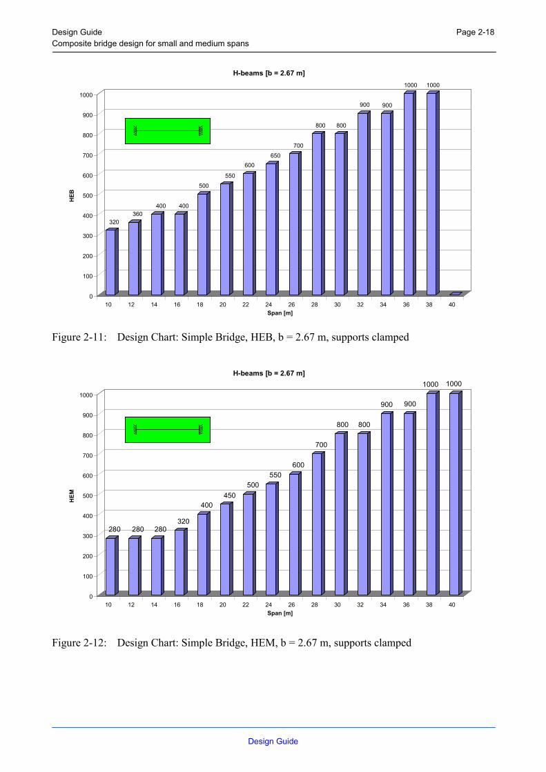
Figure 2-11: Design Chart: Simple Bridge, HEB, b = 2.67 m, supports clamped
280 280 280320
400450
500550
600
700
800 800
900 900
1000 1000
0
100
200
300
400
500
600
700
800
900
1000
HEM
10 12 14 16 18 20 22 24 26 28 30 32 34 36 38 40Span [m]
H-beams [b = 2.67 m]
Figure 2-12: Design Chart: Simple Bridge, HEM, b = 2.67 m, supports clamped

Design Guide Composite bridge design for small and medium spans
Design Guide
Page 2-19
2.4.3 Two-span bridge with end supports and the middle support pinned
2.4.3.1 H-beams with a bay width of 1.80 m
450 450500
550600
650700
800 800
900
1000 1000
0
100
200
300
400
500
600
700
800
900
1000
HEA
10 12 14 16 18 20 22 24 26 28 30 32 34Span [m]
H-beams [b = 1.80 m]
Figure 2-13: Design Chart: Two-span Bridge, HEA, b = 1.80 m, supports pinned
340360
450
550600
650700
800 800
900
1000 1000
0
100
200
300
400
500
600
700
800
900
1000
HEB
10 12 14 16 18 20 22 24 26 28 30 32 34Span [m]
H-beams [b = 1.80 m]
Figure 2-14: Design Chart: Two-span Bridge, HEB, b = 1.80 m, supports pinned

Design Guide Composite bridge design for small and medium spans
Design Guide
Page 2-20
300 320
400450
500550
600
700
800 800
900 900
1000
0
100
200
300
400
500
600
700
800
900
1000
HEM
10 12 14 16 18 20 22 24 26 28 30 32 34Span [m]
H-beams [b = 1.80 m]
Figure 2-15: Design Chart: Two-span Bridge, HEM, b = 1.80 m, supports pinned
2.4.3.2 H-beams with a bay width of 2.67 m
450 450500
550
650
800 800
900
1000 1000
0
100
200
300
400
500
600
700
800
900
1000
HEA
10 12 14 16 18 20 22 24 26 28 30Span [m]
H-beams [b = 2.67 m]
Figure 2-16: Design Chart: Two-span Bridge, HEA, b = 2.67 m, supports pinned

Design Guide Composite bridge design for small and medium spans
Design Guide
Page 2-21
360400
500550
650700
800
900 900
1000
0
100
200
300
400
500
600
700
800
900
1000
HEB
10 12 14 16 18 20 22 24 26 28 30Span [m]
H-beams [b = 2.67 m]
Figure 2-17: Design Chart: Two-span Bridge, HEB, b = 2.67 m, supports pinned
320360
400450
500
600
700
800
900 900
1000
0
100
200
300
400
500
600
700
800
900
1000
HEM
10 12 14 16 18 20 22 24 26 28 30Span [m]
H-beams [b = 2.67 m]
Figure 2-18: Design Chart: Two-span Bridge, HEM, b = 2.67 m, supports pinned

Design Guide Composite bridge design for small and medium spans
Design Guide
Page 2-22
2.4.4 Two-span bridge with end supports clamped and the middle support pinned
2.4.4.1 H-beams with a bay width of 1.80 m
450 450 450 450 450
550 550 550
650 650700
800 800
900
1000 1000 1000 1000 1000
0
100
200
300
400
500
600
700
800
900
1000
HEA
10 12 14 16 18 20 22 24 26 28 30 32 34 36 38 40 42 44 46 48 50Span [m]
H-beams [b = 1.80 m]
Figure 2-19: Design Chart: Two-span Bridge, HEA, b = 1.80 m, end supports clamped
320340 340
400 400
500
550 550
600
650 650700
800 800
900 900
1000 1000
0
100
200
300
400
500
600
700
800
900
1000
HEB
10 12 14 16 18 20 22 24 26 28 30 32 34 36 38 40 42 44 46 48 50Span [m]
H-beams [b = 1.80 m]
Figure 2-20: Design Chart: Two-span Bridge, HEB, b = 1.80 m, end supports clamped

Design Guide Composite bridge design for small and medium spans
Design Guide
Page 2-23
280 300 300 320
400450 450 450
550600 600
650 650700
800
900 900
1000 1000 10001000
0
100
200
300
400
500
600
700
800
900
1000
HEM
10 12 14 16 18 20 22 24 26 28 30 32 34 36 38 40 42 44 46 48 50Span [m]
H-beams [b = 1.80 m]
Figure 2-21: Design Chart: Two-span Bridge, HEM, b = 1.80 m, end supports clamped
2.4.4.2 H-beams with a bay width of 2.67 m
500 500 500
550 550600 600
650 650
800 800 800
1000 1000 1000 1000 1000
0
100
200
300
400
500
600
700
800
900
1000
HEA
10 12 14 16 18 20 22 24 26 28 30 32 34 36 38 40 42Span [m]
H-beams [b = 2.67 m]
Figure 2-22: Design Chart: Two-span Bridge, HEA, b = 2.67 m, end supports clamped

Design Guide Composite bridge design for small and medium spans
Design Guide
Page 2-24
400
450 450 450
500 500
550 550
600
700
800 800
900 900 900
0
100
200
300
400
500
600
700
800
900
HEB
10 12 14 16 18 20 22 24 26 28 30 32 34 36 38 40 42Span [m]
H-beams [b = 2.67 m]
Figure 2-23: Design Chart: Two-span Bridge, HEB, b = 2.67 m, end supports clamped
280 300 300 300
400450
500 500550
650700 700
800 800
1000 1000
0
100
200
300
400
500
600
700
800
900
1000
HEM
10 12 14 16 18 20 22 24 26 28 30 32 34 36 38 40 42Span [m]
H-beams [b = 2.67 m]
Figure 2-24: Design Chart: Two-span Bridge, HEM, b = 2.67 m, end supports clamped

Design Guide Composite bridge design for small and medium spans
Design Guide
Page 3-25
3 SOFTWARE
In frame of the project a computer programme named CBD (Composite Bridge Design) has been developed to pre-design composite bridges for small and medium spans. The design is based on the Eurocode.
The Software is enclosed in ANNEX A.
The calculable constructions are rectangular, simple or multispan composite bridges consisting of a prefabricated steel beam and a concrete slab. The slab can be solid or constructed using prefabricated elements. The longitudinal and transverse reinforcement is considered not to be pre-stressed.
The program is designed in three layers:
- The first layer of the program is the main menu. All main actions of the program are initialised out of the main menu using pull-down menus.
Figure 3-1: Pull-down menus of the main menu
One action is to call user-friendly dialog boxes where input data of a bridge is entered. The user is able to apply data for a complete new superstructure or edit a former specified bridge data input file. Additionally it is possible to print input or output files out of the main menu. The calculation is also started out of the main. Online-Help to the programme is available.
- The second layer of the program is represented by the dialog boxes, the user interface to apply data for the superstructure. The user can choose between the pre-design of a simple, two-span or multispan bridge with different support situations. The slab can be constructed as a solid slab or with the help of partially or fully prefabricated elements. The cross section in the field is differentiated from the cross section over the support. Rolled or welded steel girder sections are implemented. Choosing a rolled section means, that the program determines the section, increasing standard profile sections out of tables, until the checks for the ultimate limit state and serviceability limit state of EC3 and EC 4 are satisfied in all construction and final situations. For welded sections, the height of the profile is increased from 500 [mm] up to maximal 2500 [mm] in 10 [mm]-increments up to the point where the former specified limitations are satisfied.
Common materials are included in the program and additionally high-tensile steel and high-strength concrete are implemented. Studs with a variable height, diameter and steel strength can be chosen as shear connectors. The possibility to use an alternative shear connector with a user specified bearing capacity is added. The distribution of the shear connectors is up to the user and has to be checked additionally. The specification of the loads are differentiated between their type, kind, place and temporary occurrence. The specification has an influence on safety and combination factors in the checks. The self-weight of the steel girder, the concrete slab and the actions due to creep and shrinkage at t = ∞ are estimated by the program itself. Permanent ,

Design Guide Composite bridge design for small and medium spans
Design Guide
Page 3-26
traffic, temperature and breaking loads have to be added by the user. Generally loads have to be determined considering their transversal distribution over the cross section of the bridge. All checks are done for variable construction situation and final situations. Safety factors of different nations can be chosen. It is up to the user, if creep, shrinkage, moment distribution and a user specified deflection limit is taken into account.
- The third layer of the program is the calculation module. After opening an input file the pre-design calculation referring to EC 3 and EC 4 is initialised. During the calculation design points are defined at the quarter points and end points of each bridge span. All checks of the ultimate limit state and serviceability limit state are carried out at these points. Starting with the determination of the steel and composite cross sections for all construction and final situations, differentiated between field sections and sections over the support, the loads are applied and the inner forces are estimated.
Table 3-1: Construction Sequences for a solid- and fully prefabricated slab
Construction Situation
Description Load
System 1 Multispan bridges: Steel beam with a hinge
Dead load of the steel beam
System 2 Steel beam with welded hinge
Dead load of the solid slab or the fresh concrete and construction loads
System 4 Full composite action considering cracks in concrete in the hogging moment area
Infrequent and frequent load
Table 3-2: Construction Sequences for a partially prefabricated slab
Construction Situation
Description Load
System 1 Multispan bridges: Steel beam with a hinge
Dead load of the steel beam
System 2 Steel beam with welded hinge
Dead load of the partially prefabricated slab
System 3 Partial composite action Dead load of the fresh concrete and construction loads
System 4 Full composite action considering cracks in concrete in the hogging moment area
Infrequent and frequent load

Design Guide Composite bridge design for small and medium spans
Design Guide
Page 3-27
The relevant forces for each construction phase are multiplied by safety and combination factors and summed up. With the load combinations and the estimated cross sections the programme is able to perform the following checks of the ultimate limit state and serviceability limit state
Ultimate limit state of the steel girder referring to EC 3:
- ultimate resistance against positive bending
- ultimate resistance against negative bending
- ultimate resistance against positive bending moments taking interaction of shear into account
- ultimate resistance against negative bending moments taking interaction of shear into account
- ultimate resistance against shear
- ultimate resistance against torsional buckling
Ultimate limit state of the composite section referring to EC 4:
- ultimate resistance against positive bending
- ultimate resistance against shear
- ultimate resistance against negative bending moments taking interaction of shear into account
- bonding strength of the shear connectors, number of shear connectors
- ultimate resistance against torsional buckling
Serviceability limit state referring to EC 4:
- stress analysis
- crack width limitation and check of the minimal reinforcement
- deflection check
The results of each iteration step of the calculation are written into a similar named output file with the extension (.OUT). The last and relevant iteration step is summarised into a similar named data file with the extension (.RTF). The output is arranged such as the user is able to follow the result information easily. The check formats of the EC are included in the output file
INSTALL.bat installs the program in a former specified directory on the computer.

Design Guide Composite bridge design for small and medium spans
Design Guide
Page 4-28
4 ADVANCED STANDARD SOLUTIONS
4.1 Abutments
4.1.1 Abutments with expansion joints
The most common way to arrange the end supports is using expansion joints which are supposed to absorb the movements from temperature, as well as any horizontal movements of the supports. These expansion joints often have to be replaced, due to leakage of the joints. Furthermore, they lead to discomfort for the drivers and passengers of the vehicles over-passing them. In other words, the bridge in many cases would be better of without any expansion joint.
4.1.2 Abutments without expansion joints
Instead of using expansion joints the movements from temperature changes can be absorbed in the backfilling behind the backwalls, which are directly connected to the steel girders. The concept is commonly used in Sweden for bridges up to some 50-70 m total length.
Figure 4-1: Prefabricated back-wall with side-wings, used for a composite bridge.
Design Guide Composite bridge design for small and medium spans
Design Guide
Page 4-29
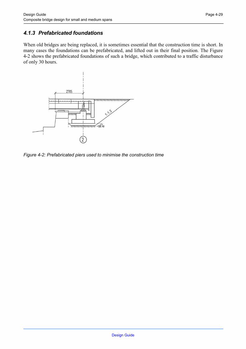
4.1.3 Prefabricated foundations
When old bridges are being replaced, it is sometimes essential that the construction time is short. In many cases the foundations can be prefabricated, and lifted out in their final position. The Figure 4-2 shows the prefabricated foundations of such a bridge, which contributed to a traffic disturbance of only 30 hours.
Figure 4-2: Prefabricated piers used to minimise the construction time

Design Guide Composite bridge design for small and medium spans
Design Guide
Page 4-30
4.1.4 Integral abutments
Experience from the U.S. shows that bridges with integral abutments are increasingly outclassing the traditional bridges with joints, the former being not only less expensive to maintain, but also more affordable to build. The concept is commonly used in USA, up to 120 m total length of the bridge.
Analysing the load bearing capacity of piles subjected to lateral movements is complex as it contains two co-dependent elements; the flexural pile and the soil. To further complicate matters, soils are often inhomogeneous.
Within a research project at Luleå University of Technology, a bridge was built in the northern Sweden, completed in September 2000.
Figure 4-3: Bridge with integral abutments.
Design Guide Composite bridge design for small and medium spans
Design Guide
Page 4-31
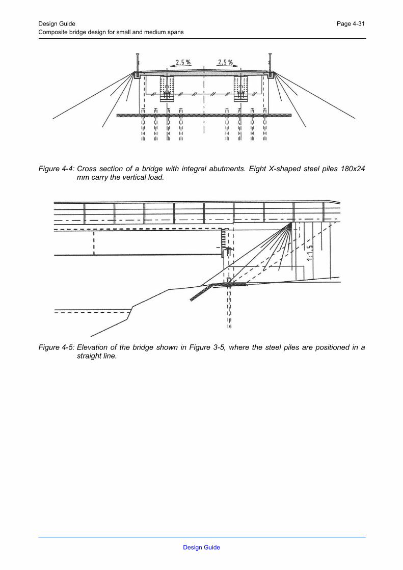
Figure 4-4: Cross section of a bridge with integral abutments. Eight X-shaped steel piles 180x24 mm carry the vertical load.
Figure 4-5: Elevation of the bridge shown in Figure 3-5, where the steel piles are positioned in a
straight line.

Design Guide Composite bridge design for small and medium spans
Design Guide
Page 4-32
4.2 Main Girder
4.2.1 Hybrid girder
Hybrid plate girders may be used in steel and composite bridges provided the limitations and the criteria for the resistance at the ultimate limit states, the serviceability limit states and fatigue, are satisfied.
At the stage of drafting of this guide, the reference is the ENV’s versions of Eurocodes and especially : ENV 1993-1-5 (November 1997), ENV 1993-1-1 (February 1992), ENV 1993-2 (October 1997) and ENV 1994-2 (December 1997). The designer should take any modification adopted in the final EN version of these documents into account.
4.2.1.1 Limitations
4.2.1.1.1 Cross-section
This guide concerns the design of hybrid plate girders for small and medium span bridges. The application of this guide covers the design of the main elements. The main elements can be symmetrical or non-symmetrical I section girders or box girders without longitudinal stiffeners in the flange.
4.2.1.1.2 Yield strength ratio
The particular focus of this guide is towards hybrid plate girders which are built-up sections where the flange plate yield strength fyf is greater than that of the web plate fyw.
According to ENV 1993-1-5, the use of hybrid girders is explicitly covered in Clause 2.2.2(6). According to this clause hybrid girders may have a flange yield strength fyf up to 2 fyw. This limitation is based on available tests in this field.
2≤≤yw
yfyfyw f
fandff (4–1)
4.2.1.1.3 Weld metal
The fabrication and erection should be in accordance with ENV 1993-2 Chapter 7.
For hybrid plate girders and at the web-to-flange junctions, the weld metal of the fillet weld should match at least with the metal of the web in terms of the mechanical properties. Elsewhere, the provisions of ENV 1993-1-1 Clause 6.6 and ENV 1993-2 Clause 6.5 should be applied.
4.2.1.2 Ultimate limit states other than fatigue
4.2.1.2.1 Classification of hybrid plate cross-section
For the classification of a hybrid plate cross-section, the basis given in ENV 1993-1-1 Clause 5.3 should be applied.

Design Guide Composite bridge design for small and medium spans
Design Guide
Page 4-33
a) Compression flange
The Table 5.3.1 of ENV 1993-1-1 should be used for the classification of the compression flange. In addition, compression flanges connected to concrete flange according to ENV 1994-2 may be classified as Class 1 sections.
b) Web
For the classification of the cross section the plastified zone in the web should be taken into account. According ENV 1993-1-5 Clause 2.2.2 (6-b), the classification and the calculation of the effective area of the web should be determined with fyf rather than fyw to consider the effect due to the plastified zone in the web.
4.2.1.2.2 Bending moment resistance
The increase of flange stresses caused by yielding of the web should be taken into account as indicated in ENV 1993-1-5 Clause 2.2.2 (6-a).
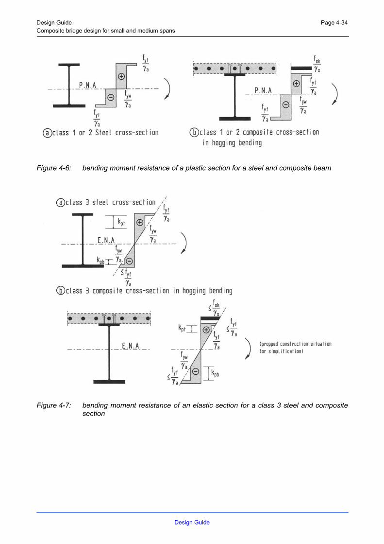
Depending on the class of the cross section, the distribution of the stresses should be one of those given in Figure 4-6 to Figure 4-8.
The effect of shear lag should be considered by the use of an effective width of the slab and of the flanges if necessary.
a) Class 1 or 2 cross-sections
The bending moment resistance should be calculated (see Figure 4-6) from a plastic distribution of the stresses in the gross cross-section according to ENV 1993-1-1 Clause 5.4.5.2 for steel cross-sections and ENV 1994-1-1 Clause 4.4 for composite cross-sections.
b) Class 3 cross-sections
The bending moment resistance should be calculated (see Figure 4-7) from an elastic distribution of the stresses in the gross cross-section according to ENV 1993-1-1 Clause 5.4.5.2 for steel cross-sections and ENV 1994-1-1 Clause 4.4 for composite cross-sections.
c) Class 4 cross-sections
In this guide, Class 4 cross-section concerns only the web due to the limitation adopted in Figure 4-8. To calculate the effective area of the web, ENV 1993-1-5 Clause 2.2.2 (6-b) indicates the use of fyf rather than fyw . The verification should be according to the expression (2-1) in Clause 2.2.1(2) of ENV 1993-1-5. In Figure 4-8 are given some examples of possible stress distributions.
Design Guide Composite bridge design for small and medium spans
Design Guide
Page 4-34
Figure 4-6: bending moment resistance of a plastic section for a steel and composite beam
Figure 4-7: bending moment resistance of an elastic section for a class 3 steel and composite
section

Design Guide Composite bridge design for small and medium spans
Design Guide
Page 4-35
Figure 4-8: bending moment resistance of an elastic section for a class 4 steel and composite
section
4.2.1.2.3 Shear resistance, shear buckling resistance and interaction between shear and bending
The shear resistance, shear buckling resistance and the interaction between shear and bending should be calculated as for homogeneous girders according to ENV 1993-2 and ENV 1993-1-5 Clauses 2.2.1 and 4.3 respectively using fyf for flanges and fyw for webs.
4.2.1.2.4 Resistance of webs to transverse forces and interaction
The resistance should be calculated according to ENV 1993-1-5 Clause 4.4.
The interaction between transverse force, bending moment and axial force should be verified according to ENV 1993-1-5 Clause 2.2.3.2.

Design Guide Composite bridge design for small and medium spans
Design Guide
Page 4-36
4.2.1.3 Serviceability limit state
4.2.1.3.1 Stresses
At serviceability limit state, ENV 1993-2 Clause 4.3(1) should be applied for hybrid plate girders.
The nominal stresses in all elements of the bridge resulting from characteristic (rare) load combinations σEd,ser and τEd,ser, should be limited as follows :
serMyserEd f ,, / γ≤σ (4–2)
serMyserEd f ,, /)3/( γ≤τ (4–3)
And for the interaction
[ ] serMyserEdserEd f ,5,02
,2
, /)(3)( γ≤τ+σ (4–4)
4.2.1.3.2 Web breathing
Hybrid plate girders should be verified as homogeneous girders against web breathing. Reference should be made to ENV 1993-2 Clause 4.4.
4.2.1.3.3 Deformations (Deflections)
In general, the effect of the yielding in the web on the deflection is negligible and may be disregarded in the calculation of the deflections of steel and composite bridges with hybrid plate girders.
When accurate deflections are required, an analysis taken into account the plastified zone in the web should be adopted.

Design Guide Composite bridge design for small and medium spans
Design Guide
Page 4-37
4.2.1.4 Fatigue
This paragraph proposes some recommendations and guidelines concerning the fatigue assessment of hybrid plate girders in steel and composite bridges with small and medium spans. By reference to homogeneous girders the main difference is the effect of the plastified zone in the web and particularly at the web-to-flange junction on the fatigue resistance of different details.
4.2.1.4.1 Limitations
All nominal stresses in the flanges should be within the elastic limits of the material. The range of the design values of such stresses shall not exceed 1.5 fyf /γMf for normal stresses or 1.5 fyw /( 3 γMf ) for shear stresses.
For hybrid plate girders, the stress ranges shall be determined by an elastic analysis of the structure under fatigue loading (ENV 1993-1-1). Stress calculations should take into account the effect of shear lag but normally without the effect of local plate buckling. For composite bridges the effect of the cracking of the concrete should also be considered.
4.2.1.4.2 Details
Figure 4-10 gives the main detail categories for hybrid plate girders for bridges.
Cope holes (see Figure 4-9 and Figure 4-10) can be adopted for hybrid plate girders. Fatigue resistance of this detail may be enhanced by the execution of a mouth shape hole rather than a circular one as indicated in Figure 4-10 and plugging the hole with weld.
Figure 4-9: Cope holes in hybrid girders

Design Guide Composite bridge design for small and medium spans
Design Guide
Page 4-38
Figure 4-10: Circular and mouth shaped cope holes

Design Guide Composite bridge design for small and medium spans
Design Guide
Page 4-39
4.2.2 Studs as shear connectors
4.2.2.1 General
For the shear connection and concrete grades in accordance with ENV 1994-2:1997, headed studs with diameters of 19,22 and 25 mm may be used. The design resistance for the ultimate limit state and the limit state of fatigue should be determined according to 4.2.2.2 and 4.2.2.3. In case of partially prefabricated elements or precast slabs the influence of appropriate infill around the studs should be taken into account, if the infill around the studs is smaller than 25 mm. See Chapter 4.2.2.2.
4.2.2.2 Design resistance of headed studs in combination with precast slabs
The design resistance of headed studs, automatically welded in accordance with EN ISO 14555 and EN ISO 13918 is given by equations (3-5) and (3-6) whichever is smaller.
v
2upRd
14
8,0Pγ
πκ= df (4–5)
( )ν
cmck2
pRd1)Ef(d25,0Pγ
ακ= (4–6)
where :
γv = 1,25 is the nominal partial safety factor for the ultimate limit state ;
d is the diameter of the shank of the stud ;
fu is the specified ultimate tensile strength of the material of the stud but not
greater than 500 N/mm2 ;
fck is the characteristic cylinder strength of the concrete at the age considered ;
Ecm is the mean value of the secant modulus of the concrete in accordance
with EN 1992-1 for normal and for lightweight concrete ;
α = 0,2 [(hsc / d) + 1] for 3 ≤ hsc / d ≤ 4
α = 1 for hsc / d > 4
hsc is the overall nominal height of the stud,
κp is a reduction factor in case of use of precast slabs taking into account the influence of the distance between the stud and the side faces of the precast element. The reduction factor should be determined from Figure 4-11 where es ≥ 5 mm is the distance between the outside of the shank of the stud and the side or front face of the precast element.

Design Guide Composite bridge design for small and medium spans
Design Guide
Page 4-40
κp
1,0
0,85
10 25
es [mm]
partially prefabricated slab precast slab with stud in groupsα
es
es
es
loes
Figure 4-11: Reduction factor κp in case of partially or totally prefabricated slabs
An inclination of the side faces of the openings in precast elements should be avoided. The design resistance according to equations (3-5) and (3-6) should be reduced by 20%, if the side faces are inclined according to Figure 4-11 and tanα ≤ 0,20.
4.2.2.3 Fatigue verification
For solid slabs, partially prefabricated slab and precast elements with studs in groups, the fatigue strength of headed studs should be determined in accordance with 6.3.8 of ENV 1994-2 but with a characteristic fatigue strength ∆τc=90N/mm2
4.2.3 Dismountable shear connectors
4.2.3.1 General
For temporary bridges and where during the design life an exchange of the concrete deck should be considered, shear connection with headed studs in combination with an additional steel plate and bolts of grade 10.9 can be provided (see Figure 4-12). The distance between the edge of the head of the bolt and the edge of the steel plate should be not less than 20mm.
precast slab or in situ concreteheaded studs
steel platebolts of grade 10.9 e2
Figure 4-12: Dismountable shear connection
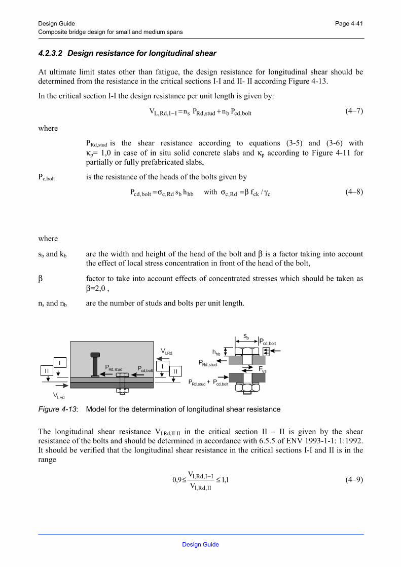
Design Guide Composite bridge design for small and medium spans
Design Guide
Page 4-41
4.2.3.2 Design resistance for longitudinal shear
At ultimate limit states other than fatigue, the design resistance for longitudinal shear should be determined from the resistance in the critical sections I-I and II- II according Figure 4-13.
In the critical section I-I the design resistance per unit length is given by:
bolt,cdbstud,RdsII,Rd,L PnPnV +=− (4–7)
where
PRd,stud is the shear resistance according to equations (3-5) and (3-6) with κp= 1,0 in case of in situ solid concrete slabs and κp according to Figure 4-11 for partially or fully prefabricated slabs,
Pc,bolt is the resistance of the heads of the bolts given by
cckRd,chbbRd,cbolt,cd /fwithhsP γβ=σσ= (4–8)
where
sb and kb are the width and height of the head of the bolt and β is a factor taking into account the effect of local stress concentration in front of the head of the bolt,
β factor to take into account effects of concentrated stresses which should be taken as β=2,0 ,
ns and nb are the number of studs and bolts per unit length.
I III II
Vl,Rd
Vl,Rd
PRd,stud Pcd,bolt
sb
hhb
Pcd,bolt
PRd,studFvs
PRd,stud + Pcd,bolt
Figure 4-13: Model for the determination of longitudinal shear resistance
The longitudinal shear resistance Vl,Rd,II-II in the critical section II – II is given by the shear resistance of the bolts and should be determined in accordance with 6.5.5 of ENV 1993-1-1: 1:1992. It should be verified that the longitudinal shear resistance in the critical sections I-I and II is in the range
1,1V
V9,0
II,Rd,l
II,Rd,l ≤≤ − (4–9)

Design Guide Composite bridge design for small and medium spans
Design Guide
Page 4-42
4.2.3.3 Fatigue verification
The fatigue resistance of headed studs for the critical section I-I should be verified according 4.2.3 for an equivalent constant shear stress range ∗τ∆ E for 2 million cycles in accordance with ENV 1994-2: 1997, where ∗τ∆ E is given by
4/d
1P1,1V
V2stud,Rd
II,Rd,l
l,EE
π
∆=τ∆
−
∗ (4–10)
where
PRd,stud is the design resistance of the headed stud according to 3.2.2.2,
Vl,Rd,I-I is the longitudinal shear resistance in the critical section II,
ns is the number of headed studs per unit length,
∆Vl,E is the equivalent longitudinal shear range at two million cycles, determined with a slope m=8 of the fatigue strength curve,
d is the diameter of the shank of the stud.
The fatigue verification of bolts in the critical section II-II should follow Section 9 of ENV 1993-2: 1997.

Design Guide Composite bridge design for small and medium spans
Design Guide
Page 4-43
4.2.4 Bolted Connections of Girders in Span
4.2.4.1 General
There are several positions to connect two girders of multi-beam bridges to each other with a bolted connection in span: these positions are limited on the one hand by the zero crossover of the maximum and on the other hand by the zero crossover of the minimum moment process (Figure 4-18).
Figure 4-14: Bolted connection of two girders for multi-beam bridges
4.2.4.2 Static design
If the connection is in the area of the positive moment distribution, the failure occurs in the bolts, the cover plates or the web of the girder. If the connection is in the area of the negative moment distribution, the failure occurs in the reinforcement of the concrete slab.
4.2.4.2.1 Dimensioning of the Reinforcement
The static dimensioning of the reinforcement is described in [EC 2.1].
Only if a negative moment is acting in the connection section, the reinforcement takes up force.
4.2.4.2.2 Dimensioning of the bolts
4.2.4.2.2.1 Ultimate Limit State
The design resistance of the bolts is described in [EC 3.1.1 – 6.5.5].

Design Guide Composite bridge design for small and medium spans
Design Guide
Page 4-44
4.2.4.2.2.2 Serviceability Limit State
High strength bolts in slip-resistant connections are described in [EC 3.1.1 – 6.5.8].
The design slip resistance of a preloaded high-strength bolt is dependent of the slip factor :, which itself dependent on the specified class of surface treatment as given in Reference Standard 8. The high strength bolts, conform to Reference Standard 3, shall be controlled tightened, in conformity with Reference Standard 8, to at least the specified minimum design preloading force Fp,Cd, which results to
subCdp AfF 7.0, = (4–11)
with: fub tensile strength of the bolt
As tensile stress area of the bolt
If other types of preloaded bolts or other types of preloaded fasteners were used, the design preloading force Fp,Cd shall be agreed between the competent authority.
All tests have shown, that no slip has been occurred in the bolted connection during the calculated lifetime.
4.2.4.2.3 Positive Resistance Moment of the Bolted Connection for Elastic Design
In this category preloaded high strength bolts with controlled tightening shall be used. Slip shall not occur at Serviceability Limit State (SLS). The serviceability shear design load should not exceed the design slip resistance. Slip is accepted in the Ultimate Limit State (ULS). The design ultimate shear load shall not exceed the design shear resistance nor the design bearing resistance.
The neutral axis of the connection section is the same as the neutral axis of the concrete-girder-cross section (without cover plates and bolts) in the area of the connection section.
Because of the test results it is not necessary to calculate the plastic resistance of the bolted connection.
The resistance results of the slip resistance of the bolts and the resistance of the concrete. The maximum stress in the concrete must be lower than the design compressive strength of the concrete fcd multiply with ".
Therefore the positive resistance moment results to
iciRdselastRd yFynFM += ∑ ,, (4–12)
with: n row of bolts
yi distance of each bolt or the force of the concrete to the neutral axis
Fs,Rd slip resistance of the bolts
Fc force of the concrete

Design Guide Composite bridge design for small and medium spans
Design Guide
Page 4-45
fcd design compressive strength of the concrete
" coefficient taking account of long term effects on the compressive strength and
unfavourable effects resulting from the way the load is applied
Figure 4-15: Positive resistance of a bolted connection for elastic design
4.2.4.2.4 Negative Resistance Moment of the Bolted Connection for Elastic Design
In this category preloaded high strength bolts with controlled tightening shall be used. Slip shall not occur at Serviceability Limit State (SLS). The serviceability shear design load should not exceed the design slip resistance. Slip is accepted in the Ultimate Limit State (ULS). The design ultimate shear load shall not exceed the design shear resistance nor the design bearing resistance.
The neutral axis of the connection section is the same as the neutral axis of the concrete-girder-cross section (without cover plates and bolts) in the area of the connection section.
Because of the test results it is not necessary to calculate the plastic resistance of the bolted connection.
The resistance results of the slip resistance of the bolts and the elastic resistance of the reinforcement (the concrete is fully cracked). The maximum stress in the reinforcement must be lower than the design strength of the reinforcement..
Therefore the negative resistance moment results to
∑∑ σ+= isisiiRdselastRd yAynFM ,, (4–13)

Design Guide Composite bridge design for small and medium spans
Design Guide
Page 4-46
Figure 4-16: Resistance of a bolted connection for elastic design (negative moment)
with: n row of bolts at one girder
yi distance of each bolt to the neutral axis
Fs,Rd slip resistance of the bolts
Fs force in the reinforcement
As total area of the longitudinal reinforcement
fsd design strength of the reinforcement
4.2.4.2.5 Critical Resistance Moment of the Web
Here the failure should be expected (following EC 3) in the web of the girder. Due to the test results it is possible to neglect the holes in the web and to calculate the resistance of the web in a distance of the thickness of the cover plate tcovpla plus half the diameter of the washer dwa (Figure 4-17).
Due to the results of the tests, for a positive action moment cracks have been detected in the cover plates and for a negative action moment in the web of the girder. No slip occurred in both cases.
Figure 4-17: Failure zone of the web

Design Guide Composite bridge design for small and medium spans
Design Guide
Page 4-47
If it is necessary to raise the critical resistance of the web, than it is possible to elongate the cover plates and to use more bolts.
4.2.4.2.5.1 Resistance Moment of a Bolted Connection for Elastic Design
In calculation it could be supposed, that the neutral axis is located in the centre of the concrete slab. So the resistance of the concrete could be neglected. This is an assumption to maximise the thickness of the cover plate (4.2.4.2.6).
Therefore, if there is no slip, the resistance moment for elastic design for the full section results to
max
2
0, y
yAkfM ii
M
ykelastRd
∑γ
= (4–14)
with: k 1.0 in tension and 1/o3 in shear
yi distance of each bolt to the neutral axis
ymax max. distance of the bolts to the neutral axis
Ai area of the failure zone (Figure 4-17)
4.2.4.2.5.2 Resistance Moment of a Bolted Connection for Plastic Design
In calculation it could be supposed, that the neutral axis is located at the level of the upper steel reinforcement in the concrete slab. So the resistance of the concrete could be neglected. This is an assumption to maximise the thickness of the cover plate (4.2.4.2.6)
Therefore, if there is slip, the resistance moment for plastic design for the net section results to
∑γ= ii
M
ykplastRd yAk
fM
0, (4–15)
with: k 1.0 in tension and 1/o3 in shear
yi distance of each bolt to the neutral axis
Ai area of the failure zone (Figure 4-17)
4.2.4.2.6 Resistance of the Cover Plate
With the elastic resistance moment (4.2.4.2.5.1), the thickness of the cover plate results to
ykplaplapla
MelastRd
fyhh
n
yMt
+
γ=
21,covcov
3cov
0max,
12
(4–16)

Design Guide Composite bridge design for small and medium spans
Design Guide
Page 4-48
And with the plastic resistance moment (4.2.4.2.5.2), the thickness of the cover plate results to
2,cov,cov
0,
playknetpla
MplastRd
yfhnM
tγ
= (4–17)
with: hcovpla the height of the cover plate
hcovpla,net the height of the cover plate minus the hole of the bolts
ycovpla,1 distance of the centre of the cover plate to the centre of the concrete
ycovpla,2 distance of the centre of the cover plate to the upper steel reinforcement in
the concrete slab
ymax distance of the lower side of the cover plate to the centre of the concrete
n number of the cover plates
Finally the maximum of these values is the proper one.
4.2.4.3 Fatigue design [EC 3.1.1 – 6.2]
The fatigue results of the tests are:
- the fatigue resistance of the connections has been much higher than calculated
- for a positive action moment cracks have been detected in the cover plates
- for a negative action moment cracks have been detected in the web of the girder
- no slip occurred in both cases
The fatigue resistance of the reinforcement is not relevant for bolted connections in span, because the lower classified detail categories of the cover plate or the web of the girder failed first.
The fatigue detail category of the bolted connection is equal to 112 for preloaded high strength bolts or preloaded injection bolts and 90 for fitted bolts or non preloaded injection bolts.
The fatigue detail category of the girder is equal to 160.
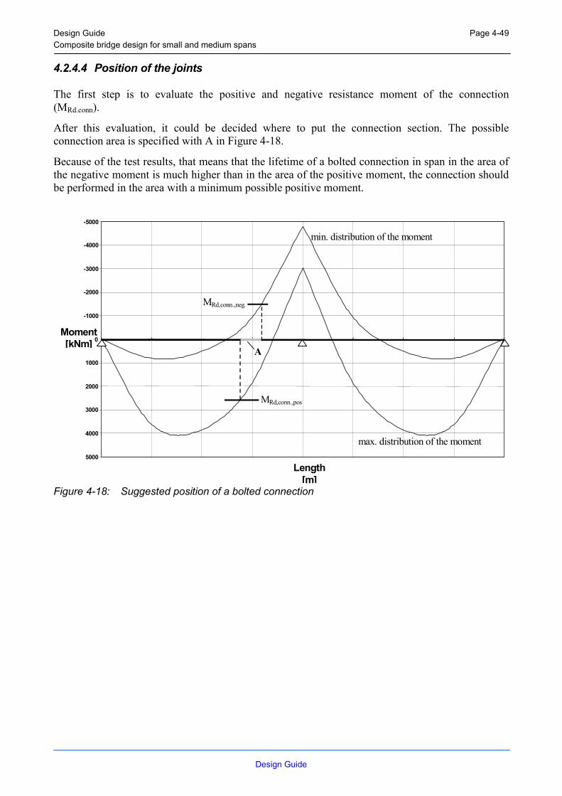
Design Guide Composite bridge design for small and medium spans
Page 4-49
4.2.4.4 Position of the joints
The first step is to evaluate the positive and negative resistance moment of the connection (MRd.conn).
After this evaluation, it could be decided where to put the connection section. The possible connection area is specified with A in Figure 4-18.
Because of the test results, that means that the lifetime of a bolted connection in span in the area of the negative moment is much higher than in the area of the positive moment, the connection should be performed in the area with a minimum possible positive moment.
Figure 4-18: Suggested position of a bol
min. distribution of the moment
M Rd,conn.,neg.
-5000
-4000
-3000
-2000
-1000
0
1000
2000
3000
4000
5000
Moment[kNm]
min. distribution of the moment
MRd,conn.,neg.
A
LDesign Guide
ted connection
max. distribution of the moment
M Rd,conn.,pos.
Length[m]
max. distribution of the moment
MRd,conn.,pos
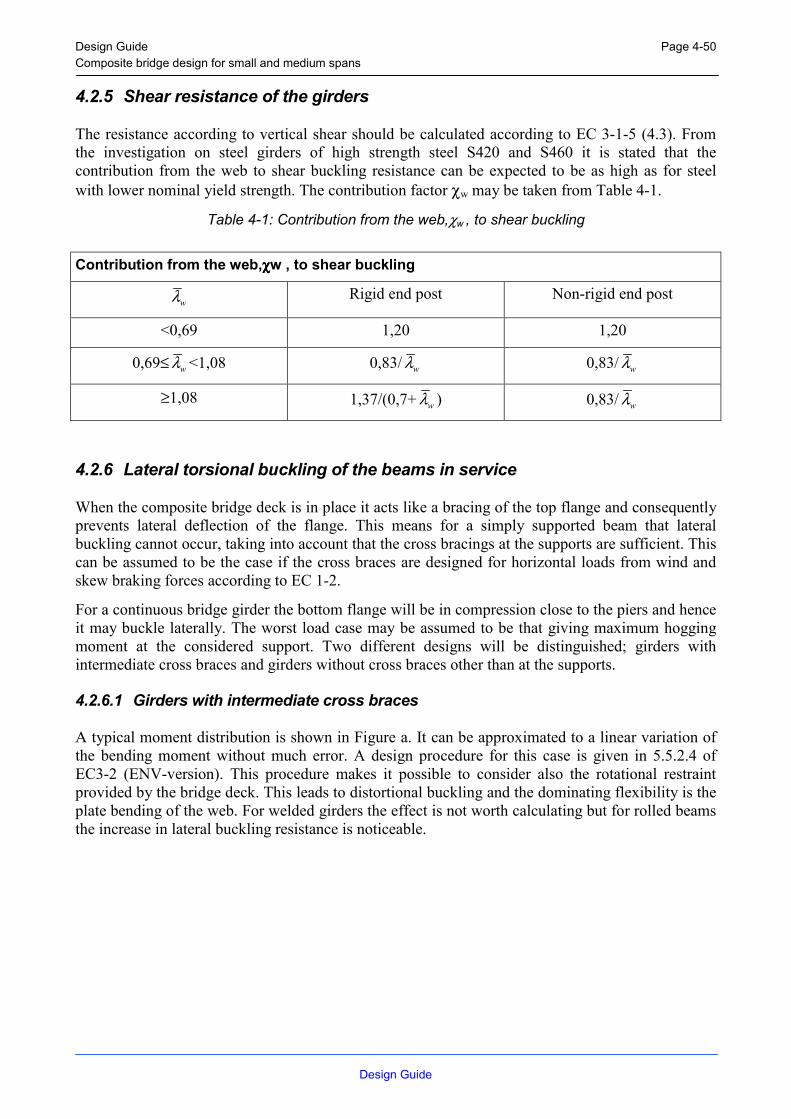
Design Guide Composite bridge design for small and medium spans
Design Guide
Page 4-50
4.2.5 Shear resistance of the girders
The resistance according to vertical shear should be calculated according to EC 3-1-5 (4.3). From the investigation on steel girders of high strength steel S420 and S460 it is stated that the contribution from the web to shear buckling resistance can be expected to be as high as for steel with lower nominal yield strength. The contribution factor χw may be taken from Table 4-1.
Table 4-1: Contribution from the web,χw , to shear buckling
Contribution from the web,χχχχw , to shear buckling
wλ Rigid end post Non-rigid end post
<0,69 1,20 1,20
0,69≤ wλ <1,08 0,83/ wλ 0,83/ wλ
≥1,08 1,37/(0,7+ wλ ) 0,83/ wλ
4.2.6 Lateral torsional buckling of the beams in service
When the composite bridge deck is in place it acts like a bracing of the top flange and consequently prevents lateral deflection of the flange. This means for a simply supported beam that lateral buckling cannot occur, taking into account that the cross bracings at the supports are sufficient. This can be assumed to be the case if the cross braces are designed for horizontal loads from wind and skew braking forces according to EC 1-2.
For a continuous bridge girder the bottom flange will be in compression close to the piers and hence it may buckle laterally. The worst load case may be assumed to be that giving maximum hogging moment at the considered support. Two different designs will be distinguished; girders with intermediate cross braces and girders without cross braces other than at the supports.
4.2.6.1 Girders with intermediate cross braces
A typical moment distribution is shown in Figure a. It can be approximated to a linear variation of the bending moment without much error. A design procedure for this case is given in 5.5.2.4 of EC3-2 (ENV-version). This procedure makes it possible to consider also the rotational restraint provided by the bridge deck. This leads to distortional buckling and the dominating flexibility is the plate bending of the web. For welded girders the effect is not worth calculating but for rolled beams the increase in lateral buckling resistance is noticeable.

Design Guide Composite bridge design for small and medium spans
Design Guide
Page 4-51
M2
M1
Figure 4-19: Typical moment distribution of bending moment close to a pier.
4.2.6.2 Girders without cross braces other than at support
As suggested in 4.5.1.7 of this report it is sometimes feasible to delete all intermediate cross braces. This is only of interest for rolled beams due to the stability during erection, see 4.5.3. In this case the lateral buckling of the bottom flange will cause lateral deflection of the whole bottom flange and the critical hogging moment will depend on the whole moment distribution. The design procedure in 5.5.2 of EC3-2 is applicable but it exclude any information about the critical moment. Solutions for continuous girders with the top flange braced can be found in Nylander, 1964, Hanswille, 2000 and in Hanswille et al 1998. The former articles of Hanswille neglects the St. Venant torsional stiffness. The latter articel takes the St. Venant torsional stiffness into account. A summary is given below.
The system is defined in Figure 4-20. The distribution of bending moments is characterised by M0, which is the maximum sagging moment if the span is considered as simply supported, the largest hogging moment α M0 and the smaller hogging moment ψ α M0, see Figure d. The rotational restraint stiffness cζ is defined in Figure c and the critical hogging moment is expressed as follows.
Figure 4-20: Definition of system and notations. S is the centre of gravity of the structural steel
section and M is its shear centre.

Design Guide Composite bridge design for small and medium spans
Design Guide
Page 4-52
Cross section and notations
Stiffness P,cϑ due to deformations of the web s
3w
2a
aP, h
t1
E41c
ν−=ϑ
Stiffness SL,cϑ of the cracked concrete slab a
)JE(kc IIcSL, =ϑ
a span length of the slab perpendicular to the axis of the beam (EJc)II flexural stiffness of the cracked slab in transverse direction k factor taking into account the supporting conditions of the slab (k=2 for a simply supported and k=4 for a continuous slab)
Effective stiffness cϑ SL,P, c
1c
1c1
ϑϑϑ+=
Figure 4-21: Definition of rotational restraint stiffness cζ .
2 2
,
( ) 2 ayD M Pz D Mz
e st y
Jz z ik z rz J
+ += + −
2
,2
1( )
Dcr T eff
z
E JM GJk L
ωπβ
= +
( ) (1,5 0,5 )T eff TGJ A GIψ= −
4 / ( )Dc L E Jϑ ωη =
A parameter given in Figure d
Aa area of the structural steel section

Design Guide Composite bridge design for small and medium spans
Design Guide
Page 4-53
As area of reinforcement
E modulus of elasticity for structural steel section
G shear modulus for structural steel section
Jay second moment of area of the structural steel section about the y-axis
Jaz second moment of area of the structural steel section about the z-axis
JωD = Jaf,z hs2
Jaf,z second moment of area of the bottom flange of the steel section about the z-axis
Jst,y second moment of area of the composite section about the y-axis but neglecting concrete
JT St. Venant torsion section constant of the structural steel section
hs distance between the centroids of the flanges
ip2 = (Jay + Jaz)/Aa
ze = Jay/(zstAa)
zst = Aszs/(Aa + As)
zs coordinate of the reinforcement
zst coordinate of the centroidal axis of the composite section, but neglecting concrete
zD coordinate of lateral restraint related to the shear centre of the structural steel section
zM coordinate of shear centre
zpM coordinate of transverse load pz related to the shear centre
rMz 2 21 ( ) 2 My
z y z dA zI
= + −
∫
β effective length factor from Figure d
νa Poisson’s ratio for structural steel
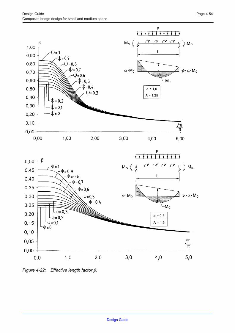
Design Guide Composite bridge design for small and medium spans
Design Guide
Page 4-54
Figure 4-22: Effective length factor β.

Design Guide Composite bridge design for small and medium spans
Design Guide
Page 4-55
4.2.6.3 WORKED EXAMPLE
For the end span of a composite beam in Figure e the critical bending moment is determined based on the presented method. The slab is continuous in transverse direction
Properties of the structural steel profile (HE 800 A):
Aa = 286 cm² Jay = 30,34 cm²m² Jaz = 1,26 cm²m²
Jaf,z = Jay/2= 0,63 cm2m2 JT = 0,0597 cm²m² 2pi = (30,34+1,26)/286 = 0,11 m2
Properties of the composite section neglecting concrete:
Ast = 286 +30 = 316 cm² zs = -(0,79/2 + 0,1) = 0,495 m
Jst,y = 30,34 + (286 30 0,495²) / 316 = 37 cm²m² zst= - 0,495 ⋅30/316= -0,047 m
Figure 4-23: Cross-section and loading conditions
With the flexural stiffness of the concrete slab (EJc)II = 4550 kNm2/m the effective stiffness of the torsional restraint cϑ results from Figure c
m/kNm5,255
2,765,1
3,0121000
41
ht
1E
41c
3
2s
3w
2a
aP, =
−=
ν−=ϑ
m/kNm3640
545504
a)EJ(kc IIc
Sl, ===ϑ

Design Guide Composite bridge design for small and medium spans
Design Guide
Page 4-56
2391
36401
5,2551
c1
c1
c1
Sl,P,=+=+=
ϑϑϑ
⇒ cϑ= 239 kNm/m
With zD = -0,381m and zM = 0 and rMz = 0 for the double-symmetrical structural steel section the values ze and kz are given by:
aa,st
aye A
Jz
z = m26,2286047,0
34,30 −=⋅−
=
y,st
ayD
e
2P
2D
z II
z2z
izk
+
+= m68,0
0,3734,30)381,0(2
26,2²11,0)²381,0( −=
−⋅−
−+−=
The warping constant JωD and the factor ηbecomes.
JωD= Jaf,zhs2 = 0,63*0,762² = 0,366 cm²m4
4 4239 20 70,5321000 0,366D
c LE J
ϑ
ω
η ⋅= = =⋅
The effective length factor β = 0,17 results from figure d with α = 1 and Ψ = 0. The effective St. Venant torsional stiffness (GJT)eff and the elastic critical bending moment Mcr are given by
+= eff,T2
B
D2
zcr GJ
)L(
JEk1M
β
π ω
kNm109740597,081005,125,1)²2017,0(366,021000²
68,01Mcr −=
⋅⋅⋅+
⋅⋅π
−=

Design Guide Composite bridge design for small and medium spans
Design Guide
Page 4-57
4.2.6.4 REFERENCES
Nylander, H. Stability of continuous I beams with top flanges braced in a lateral direction, Bulletin No. 50 of the Division of Building Stratics and Structural Engineering, Royal Institute of Technology, Stockholm 1964
Hanswille, G. Lateral Torsional buckling of composite beams. Comparison of more accurate methods with Eurocode 4, Procedings of the conference in Banff, Alberta, Canada. May 28-June 2, 2000. Volume 2.
Hanswille, G., Lindner, J., Münich, D. Lateral torsional buckling of composite beams. Stahlbau 67, 1998.
4.2.7 Detailing of the cross beams or cross braces
The crossbeams of I-girder bridges have several purposes. These are mainly:
1) to guarantee the stability during lifting, launching and casting
2) to guarantee the stability of the lower flange near support
3) to take up forces from torsional moments when the bridge is situated in a horizontal curve
4) to transfer horizontal forces from wind etc. from the steel girders to the concrete deck
5) at supports, the crossbeams serve as lifting points if the bearings have to be replaced
6) furthermore, the web stiffeners to which the crossbeams are connected will prevent the web from buckling.
It is important that the detailing is adjusted for the workshop, with no expensive welding to be performed at the site.
Three main types of crossbeams are:
- Trusses with rolled or welded profiles - Welded crossbeams - Hot-rolled crossbeams
The first alternative often offers a superior flexural rigidity, but the costs from welding or bolting the truss can be high.
The second alternative can be very useful for crossbeams at support, where the horizontal forces will be transferred to the piers. As indicated above, they are often designed to carry the dead load of the bridge, in case the bearings will have to be replaced in the future.
The third alternative is commonly used in Sweden, with e g rolled U-profiles. For higher beams, L-profiles used as diagonals can increase the flexural rigidity.

Design Guide Composite bridge design for small and medium spans
Design Guide
Page 4-58
Figure 4-24: Crossbeam made out of hot rolled UPE 300.
Figure 4-25: Crossbeam using UPE 300 and L 100x100x10.

Design Guide Composite bridge design for small and medium spans
Design Guide
Page 4-59
4.3 Concrete Deck
4.3.1 Joints in fully prefabricated slabs
One solution is to use prefabricated concrete slabs with dry joints. Hence the joints are dry, special concern has to be taken into account concerning the vertical wheel load from a vehicle passing over the joint. If there is no physical contact between the elements in the joint, then the elements will move separately from each other in the vertical direction. The vertical movement will affect the isolation and bitumen on top of the element in a negative way.
In order to prevent this vertical movement, a solution of overlapping concrete tongues has been developed. In Figure 4-26 the overlapping concrete tongues are shown.
Figure 4-26: Scaled model of fully prefabricated concrete elements, showing the overlapping concrete tongues.
Hence the concrete can not resist high-tension stress it is of great importance that the concrete tongues will be properly reinforced in such a way that the reinforcement will be able to resist the tension stress caused by the wheel load. Figure 4-27 shows a typical solution of one way to reinforce the concrete tongues.
Figure 4-27: Typical solution of one way to reinforce the concrete tongues
The cover of reinforcement on the front of the concrete tongues may possibly be reduced due to the fact that this surface is always protected from water. A reduction of the cover of reinforcement would make it possible to place the reinforcement even further out in the concrete tongues. That would be positive for the resistance. Or it would also be possible to reduce the size of the tongues, which will make it easier to assemble the element on site. Figure 3.3-3 shows a fully prefabricated element.

Design Guide Composite bridge design for small and medium spans
Design Guide
Page 4-60
Figure 4-28: Fully prefabricated concrete element.
To achieve composite action between the steel and the concrete it is necessary to connect the concrete to the steel beam. The method normally used is applying headed studs to achieve the composite action. The shear connectors have to be embedded into the concrete slab. One solution, that will keep the prefabrication rate high, is to make a void channel, a trough, on the underside of the concrete slab. The trough in the element will surround the headed studs on the steel flange. Several grout holes will be placed on top of the element to make it possible to fill the trough with concrete on site. Several air holes between the grout holes should also be applied. The air holes are important in order to prevent air pockets inside the trough after casting.
This method gives a dry surface that can be covered with isolation and bitumen immediately. Therefore it is possible to cast a bridge in winter times. If the temperature drops under –20 °C the deck can be heated by radiators. Additionally, due to the fact that the surface is dry, it is possible to cut the construction time.
Inside the trough transverse rebars are placed in order to prevent a collapse of the console during erection and to prevent the concrete to split around the studs. It is important that the spacing of the transverse rebars in the trough and the spacing of the headed studs is co-ordinated to prevent problem during erection. Figure 4-29 shows a section of the element and the steel beam.
Figure 4-29: Section of element and steel beam.

Design Guide Composite bridge design for small and medium spans
Design Guide
Page 4-61
The concept of prefabricated concrete elements with dry joints is applicable for simply supported bridges when the joints are in compression. The concrete slabs will then act like a continuos concrete slab if the fit between the concrete elements is good enough. According to tests and full scale construction match-casting is satisfactory. When the concept is used for a multiple span bridge the joint openings over intermediate supports have to be considered. The joints will open horizontally because of the strains in the top flange. This in turn will increase the vertical movement between adjacent elements when a wheel passes. The isolation and bitumen may suffer damage from these movements. It is also of great importance to correctly estimate the forces on the headed studs and to check their fatigue resistance. A full-scale test is the recommended next step in the development of this concept.
4.3.2 Concrete technology for prefabricated slabs and in situ concrete
The competitiveness of composite bridges depends on several circumstances such as site conditions, local costs of material and staff and the contractor’s experience. One major advantage compared to concrete bridges is that the steel girders can carry the weight of the formwork and the wet concrete, which means that there is no need for temporary structures. Another advantage are the savings in construction time, which saves some money for the contractor but is even more comfortable for the road users; a fact that is usually neglected when considering advantages and disadvantages of bridge designs.
Different construction methods have been developed to improve either one or both of these advantages. Generally the methods can be divided up into three main groups:
- the full in-situ concrete method: the whole slab is poured in place - the full precast concrete method: the whole slab is a precast unit - a combination of both: a precast unit is used as formwork and supplemented by an
in-situ concrete layer, so that a two parted slab is created
The above-mentioned methods are varied slightly regarding special properties in order to emphasise certain advantages, so that they can be divided up into subgroups.
In the following unit the construction methods are described and their advantages and disadvantages are mentioned.
4.3.2.1 The full in-situ concrete method
The steel girders are laid over the gap that has to be bridged. There after the formwork for the concrete slab is erected on the steel girders. If statically necessary the horizontal rigidity is improved by integrating reinforcing braces. Now the shear connectors are welded onto the steel girder and the reinforcement is installed. Thereafter the concrete is poured. After the time of after treatment the surface is sealed. The formwork often makes a complicated static necessary that in complexity might surpass the one of the bridge itself.
On the other hand it enables the architect to design forms that are not possible to build with precast units. Except for the welding, which also can be done by the steel company, there is nothing to do on site that requires especially skilled workers so that the work can be executed by a large number of companies without a special preparation. At least for the customer this has the advantage, that a great competition between the executing companies on the marked exists and so drops the prices and makes it easy to find an adequate firm.
This construction method results in that the steel girders carry the whole dead load of the bridge’s superstructure and in addition the weight of the formwork during construction time. So extra horizontal reinforcing braces are almost essential and the steel girders must be dimensioned bigger.

Design Guide Composite bridge design for small and medium spans
Design Guide
Page 4-62
The total amount of steel is the highest of all methods. Due to the formwork the execution time is very high and man-hours are numerous. The whole shrinkage of the concrete affects the bridge. Fore the whole term of concreting it is essential that the environmental temperature is above 5°C what makes a construction in winter terms impossible in colder tempered zones such as Northern Europe.
However, since the required techniques are quite easy to execute it has become the most popular solution to set up a composite bridge.
Table 4-2 gives a brief summary of the advantages and disadvantages of the conventional concreting method.
Table 4-2: Summary of the advantages and disadvantages of the full in-situ concrete method
Advantages Disadvantages
- almost each design of the slab is possible- large number of capable firms cause
competition and low prices - most popular method
- no composite action for dead load - long construction time - large amount of man-hours - large amount of steel is used - impossible in winter terms with
temperatures below 5°C

Design Guide Composite bridge design for small and medium spans
Design Guide
Page 4-63
4.3.2.2 The concrete slab as full precast unit
Precast units are laid on rolled steel joist with pre-mounted shear connectors. As it is not planed to fix in mortar to the joints afterwards, a dry construction method has to be used. In order to receive a good fit between the elements one finished element should be used as formwork for the next one during production, what make a numeration of the elements necessary. The connection between the elements should be made using special dowels. Within one day the units can be mounted and afterwards the elements can be prestressed by tightening four M24 bolts at each end of the girders. Thus the steel girders was used as tension bars. The construction can be made during winter down to temperatures about –10°C but in this case the environmental temperature has to be increased by at least 15K to concrete the connections between the slab and the girders. To achieve this raise in temperature the bridge e.g. can be covered by plastic film and heated using gas heatings. As the temperature rise to 5°C the concrete can be injected to the shear connectors through holes with a diameter not smaller than 20mm in the precast units.
While using precast units has the advantage of high quality concrete and gives the opportunity of surveillance it also requires a high accuracy producing the units. Obviously very exact working is required producing the precast units and mounting the shear connectors so that later when positioning the elements no problems occur due to shear connectors that get into conflict with the reinforcement of the slab.
As said before one advantage of composite bridges is the possible short construction time. The most favourable way of constructing composite bridges in order to save time is the above mentioned one. In Sweden an investigation was carried out in order to determine the costs that might be saved by a shorter construction phase. The investigation shows a possible time saving of about ten weeks not yet considered the possible disturbance of cold weather when concreting is impossible. The possible savings where calculated referring to a real carried out project and assuming that the time saving of each road user, using the bridge, is 5 minutes, that daily 2000 cars pass the bridge and that one hour values approximately 10 EURO for the road user. Due to that assumptions the sum of savings after 10 weeks is 117000 EURO. On the other hand, the problem is that no customer considers this fact what is quite understandable as nobody who is concerned with the decision how to build the bridge has to pay these expenses. So this argument might be a political question.
The following table gives the advantages and disadvantages of the use of fully prefabricated concrete slabs in short:
Table 4-3: Summary of the advantages and disadvantages of the concrete method using the concrete slab as full precast unit
Advantages Disadvantages
- high and equal concrete quality - shortest construction time of all methods - best solution for the road users - reduces man-hours due to work in
fabrics - set-up is possible in freezing periods - reduced forces from shrinkage as the
elements get to the site older
- high technical know-how is necessary - this includes high costs - limited design possibilities - steel girders carry the whole dead load - only very few precast unit factories are able to
the job - only few companies have experience with that
method

Design Guide Composite bridge design for small and medium spans
Design Guide
Page 4-64
4.3.2.3 Precast units supplemented with in-situ concrete
This method has to be divided up into two major groups. It can be carried out so, that the precast unit is just a permanent formwork. It is also possible to give the precast unit a static function in longitudinal direction. This method was improved by the SSF company in Germany.
The basic idea using these precast units is to simplify the formwork. Prefabricated elements are laid as formwork onto the steel girders that are mounted equal to the other construction methods. Next the reinforcement is installed and the concrete is poured from the middle of the bridge to the ends. The direction of concreting is quite important in order to avoid cracking. Starting in the middle lets deflect the bridge first so that when concreting the locations with negative moments and deflections, they already have their final forms. So the just poured concrete does not get subject to tension. To ensure the transmission of shear stress, the shear connectors are so long that they pass through the precast unit and enter into the in-situ concrete slab. Also shear garlands are mounted that connect the precast unit and the in-situ concrete. This sequence of construction results in that the whole dead load of the bridge is carried in longitudinal direction by the steel girders. As already mentioned other ways of building have been developed in order to give the prefabricated elements also in longitudinal direction a static function.
One possibility is to fix in mortar to the transverse joints before poring the in-situ concrete. This however requires an extra work step and extra costs. The advantage is that the main dead load of the bridge, the load of the reinforcement and the in-situ concrete, is carried by the partly composite girder. The precast units act as compression boom and give the construction a better horizontal stiffness while concreting. Horizontal braces are not a must. In every case the amount of construction steel required is reduced.
Table 4-4 sums up the advantages and disadvantages of the above described concrete method.
Table 4-4: Summary of the advantages and disadvantages of the concrete method using precast elements as formwork
Advantages Disadvantages
- no additional formwork is needed - short construction time - possibility of reducing effects from shrinkage- especially if composite action is activated
first the amount of steel that is necessary is reduced as the dead load is carried by the composite girder
- more complicate technique that is not executable for every company
- restricted design possibilities - long transportation ways as only a few
factories can produce the elements
The SSF engineering society improved this method again. They developed a type of composite girder that can be almost completely prefabricated in the factory. These have an upper boom which acts as an economical cross section under compression, as a shell element for the bridge floor slab and as a horizontal stabilisation. Constructing and tilting braces are not longer needed for concreting the in-situ concrete plate. The amount of steel required is once again considerably reduced, since this is determined by the amount needed in construction and not the amount contained in the bridge structure. Simple connection rod links in the support area allow the girders to be coupled in the construction phase, in order to achieve a continuous effect. After the installation and reinforcing stages, the in-situ concrete can be pored continuously and therefore more economically. The already executed projects include large bridges over valleys as well as double-span bridges over motor ways and show that also this very special method which is only supported by a few precast unit factories can be favoured by certain customers. However, it remains

Design Guide Composite bridge design for small and medium spans
Design Guide
Page 4-65
a very special solution and includes a very complicate transportation as the girders can not be piled up. Due to the fact that only a few factories support the method, long transportation ways are almost sure, this might be the most serious problem for this method to become more popular.
The advantages and disadvantages using this invention are given in Table 4-5.
Table 4-5: Summary of the advantages and disadvantages using the above mentioned invention
Advantages Disadvantages
- The high quality of the finished structure keeps maintenance costs low, due to the strong design with easily accessible steel girders and a monolithic in-situ concrete slab
- Extensive prefabrication of the girders reduces the amount of work on the building site, so that construction deployment is very economical with efficient construction time
- The concrete flanges that form the upper boom make buckling braces in the steel girders unnecessary, considerably reduce the amount of steel used in construction, since the composite material is mounted in advance, and increase the tilt resistance, i.e. no assembly braces are needed.
- The tall girder-slab composition is not pile able and makes huge trucks necessary for transportation.
- High costs due to low competition - The rare available precast unit fabrics make
far transportation necessary.
Regarding all the mentioned arguments it is impossible to favour one of the above mentioned construction methods. However it is obvious that the main disadvantage of the more developed methods, which all include the use of precast units, is the required know-how. Another disadvantage is that only a few precast unit fabrics are able to produce the required elements. If it would be possible to raise political interest in the costs caused by traffic disturbance the fastest method would always be the most favourable. Only the dry construction method as tested in Sweden allows construction during freezing period. Since these arguments only apply to very few bridges or to anyone, the use of pre-concreted elements as formwork seems to be the most reasonable method. The very special solution of SSF’s VFT© is only reasonable for very few opportunities since transportation costs can be too high.
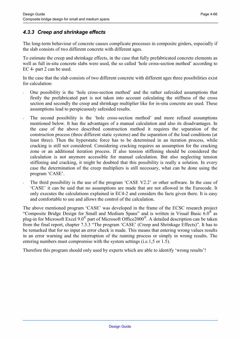
Design Guide Composite bridge design for small and medium spans
Design Guide
Page 4-66
4.3.3 Creep and shrinkage effects
The long-term behaviour of concrete causes complicate processes in composite girders, especially if the slab consists of two different concrete with different ages.
To estimate the creep and shrinkage effects, in the case that fully prefabricated concrete elements as well as full in-situ concrete slabs were used, the so called ‘hole cross-section method’ according to EC 4- part 2 can be used.
In the case that the slab consists of two different concrete with different ages three possibilities exist for calculation:
- One possibility is the ‘hole cross-section method’ and the rather safesided assumptions that firstly the prefabricated part is not taken into account calculating the stiffness of the cross section and secondly the creep and shrinkage multiplier like for in-situ concrete are used. These assumptions lead to perspicuously safesided results.
- The second possibility is the ‘hole cross-section method’ and more refined assumptions mentioned below. It has the advantages of a manual calculation and also its disadvantages. In the case of the above described construction method it requires the separation of the construction process (three different static systems) and the separation of the load conditions (at least three). Then the hyperstatic force has to be determined in an iteration process, while cracking is still not considered. Considering cracking requires an assumption for the cracking zone or an additional iteration process. If also tension stiffening should be considered the calculation is not anymore accessible for manual calculation. But also neglecting tension stiffening and cracking, it might be doubted that this possibility is really a solution. In every case the determination of the creep multipliers is still necessary, what can be done using the program ‘CASE’.
- The third possibility is the use of the program ‘CASE V2.2’ or other software. In the case of ‘CASE’ it can be said that no assumptions are made that are not allowed in the Eurocode. It only executes the calculations explained in EC4-2 and considers the facts given there. It is easy and comfortable to use and allows the control of the calculation.
The above mentioned program ‘CASE’ was developed in the frame of the ECSC research project “Composite Bridge Design for Small and Medium Spans” and is written in Visual Basic 6.0® as plug-in for Microsoft Excel 9.0® part of Microsoft Office2000®. A detailed description can be taken from the final report, chapter 7.3.3 “The program ‘CASE’ (Creep and Shrinkage Effects)”. It has to be remarked that for no input an error check is made. This means that entering wrong values results in an error warning and the interruption of the running process or simply in wrong results. The entering numbers must compromise with the system settings (i.e.1,5 or 1.5).
Therefore this program should only used by experts which are able to identify ‘wrong results’!

Design Guide Composite bridge design for small and medium spans
Design Guide
Page 4-67
4.3.4 Cracking of the joints and of the slabs
A comparison of 21 test results found in literature with the calculated values of the crack width according four different calculation methods and the interpretation of this comparison was carried out in the frame of the ECSC research project “Composite Bridge Design for Small and Medium Spans”. From the that the following conclusion can be drawn:
- The calculation methods according to [1] and [2] work very well.
- The ENV 1994-2 : 1997 gives simplified design rules to avoid impermissible cracks, for example values of minimum reinforcement, a table of maximum bar diameter and maximum bar spacing are given.
- The simplified design rules given in ENV 1994-2 : 1997 are in a good accordance with the results evaluated with the calculation methods according to [1].
In conclusion the simplified design rules are applicable to composite bridges in small and medium spans made of normal or high strength steel and in-situ or prefabricated concrete slabs. Only the influence of creep and shrinkage of partially prefabricated concrete slabs could not clarified so that in this case safesided assumptions are recommended.
For a more refined calculation of the crack width by experts the calculation method according to [1] should be used. [1] ECSC-Research Project “Composite Bridge Design Improvement for High Speed Railways”
– Report 4. “Composite Behaviour at Intermediate Supports”, Agreement 7210-SA/128, University of Wuppertal, March 1998
[2] Maurer, R.: “Grundlagen zur Bemessung des Betongurtes von Stahlverbundträgern”, Dissertation, TH-Darmstadt, 1992
4.3.5 Vibration of bridges
The measurements on 7 composite bridges and their evaluation as well as an extensive parameter-study carried out using the FE-Program DYNACS can be summarised as follows:
- For composite bridges in small and medium spans usually no adverse comments of pedestrian crossing the bridge simultaneously with traffic occurred.
- Due to some strong perception of vibration occurred in one of the carried out measurements it seems possible that the application of high strength steel and concrete slabs of low weight in future result in vibration problems.
- If it is necessary composite bridges should be examined using VDI-Standard 2057.
- Finally it can be stated that the FE-Program DYNACS (developed from the Institute of Steel Construction, RWTH Aachen) is useful to predict the dynamic behaviour of composite bridges of small an medium spans under vehicle traffic.

Design Guide Composite bridge design for small and medium spans
Design Guide
Page 4-68
4.4 Cross girder
For the structural design of a concrete cross girder section, two general designs may be considered in order to limit the stress in the concrete.
4.4.1 Connection always in negative moment area
If the connection is always in a negative moment area, the connection should be perform with a concrete cross girder and thick cap plates (Figure 4-30).
Figure 4-30: Concrete cross girder with thick cap plates
The thickness of the welds results of (4.4.3.3) and the thickness of the cap plates results of (4.4.3.1).
It is also possible to apply the studs only below the neutral axis (in the compression zone).
4.4.2 Connection in alternating moment area
If the connection is in a alternating moment area, the connection should be perform with a concrete cross girder, thick cap plates and tension anchoring (Figure 4-31).
Figure 4-31: Concrete cross girder with thick cap plates and tension anchoring

Design Guide Composite bridge design for small and medium spans
Design Guide
Page 4-69
The thickness of the welds results of (4.4.3.3 and Figure 4-34) and the thickness of the cap plates results of (4.4.3.1).
4.4.3 Static design
4.4.3.1 Dimensioning of the cap plate
For a uniform distribution of load on an area A0 (Figure 4-32) the concentrated resistance force may be determined following [EC 2.1 – 6.7].
A0 tf θ ≤ arctan (0.5)
b
tcp
bc
tc A1
Figure 4-32: Determination of areas in partially loaded areas
Therefore the thickness of the cap plate tcp results to the minimum of
btandtt cpfcp 22 ≤≤ (4–18)
with: tf and b of the flange of the steel girder
because the highest stress occurs in the lower flange of the steel girder.
4.4.3.2 Dimensioning of the reinforcement
The dimensioning of the reinforcement is described in [EC 2.1].
4.4.3.3 Dimensioning of the welds
For welding the thick cap plates on the girder, there are two options. First it is possible to make a fillet weld all around the profile (Figure 4-33)
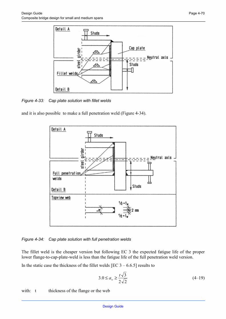
Design Guide Composite bridge design for small and medium spans
Design Guide
Page 4-70
Figure 4-33: Cap plate solution with fillet welds
and it is also possible to make a full penetration weld (Figure 4-34).
Figure 4-34: Cap plate solution with full penetration welds
The fillet weld is the cheaper version but following EC 3 the expected fatigue life of the proper lower flange-to-cap-plate-weld is less than the fatigue life of the full penetration weld version.
In the static case the thickness of the fillet welds [EC 3 – 6.6.5] results to
2230.3 taw ≥≤ (4–19)
with: t thickness of the flange or the web

Design Guide Composite bridge design for small and medium spans
Design Guide
Page 4-71
and the thickness of the full penetration welds [EC 3 – 6.6.5] at the outside of the flanges results to
3
2 fw
ta ≥ (4–20)
and at the inside to
flange.theofareathein
3
andwebtheofareathein2
fw
ww
ta
ta
≥
≥ (4–21)
In the centre of the full penetration welds in the web there is a gap of 2 mm.
4.4.4 Fatigue design [EC 3.1.1 – 6.2]
The fatigue results of the tests (only the fillet welded solution has been tested 2 times) are:
- the fatigue resistance of the connections has been much higher than calculated
- the fillet welds failed first, but in both cases no crack growth has been occurred
- the main cause of failure has been the failure of the reinforcement
The fatigue detail category of the fillet welded joint is equal to 36* and of the full penetration welded joint 40 up to 80 in subject to the geometry of the jointed details.
The fatigue detail category of the reinforcement is 162.5 at 106 cycles [EC 2.1 - 6.8.4].
The fatigue detail category of the girder is equal to 160.
4.4.5 Example
For example of the cross girder solution in the following the three span bridge in Differdange (South of Luxembourg) is shown (Figure 4-35).
The bridge carries the Differdange town centre bypass road over the 9 tracks of a main railway line. Spans of the heavily skewed and curved 12.75 m wide bridge are 25 – 40 – 25 m long. The 6 main girders are 1 m deep rolled beams (HL 1000 M / W40x277) in high strength Fe E 460 – HISTAR QST steel grade.
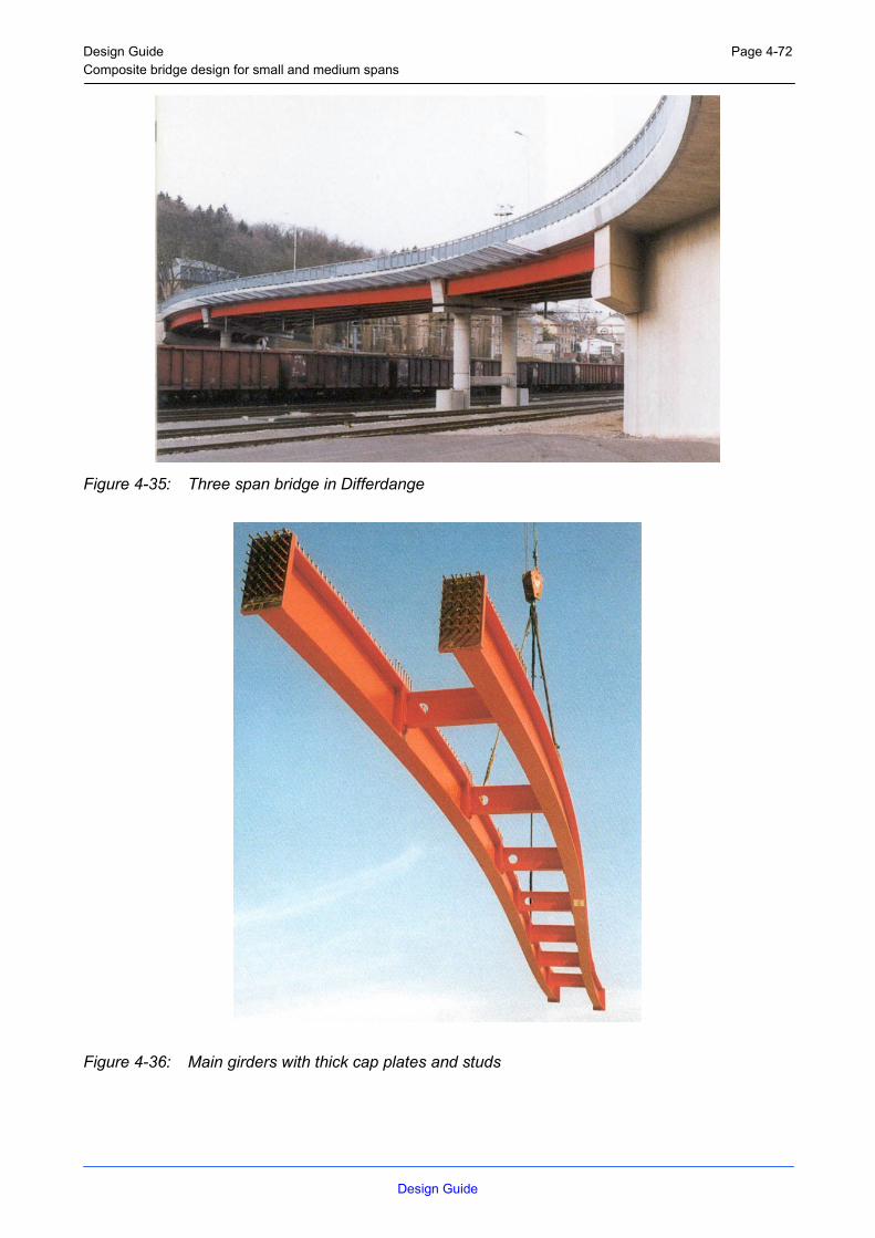
Design Guide Composite bridge design for small and medium spans
Design Guide
Page 4-72
Figure 4-35: Three span bridge in Differdange
Figure 4-36: Main girders with thick cap plates and studs

Design Guide Composite bridge design for small and medium spans
Design Guide
Page 4-73
Figure 4-37: Plan of the connection section on support
4.4.6 Recommendations
If the connection is always in a negative moment area, the connection should be perform with a concrete cross girder and thick cap plates Figure 4-30. The using of a fillet weld is the better solution to weld the profile on the cap plate, because of the advantages of the simple installation of the bending-, shear- and splitting-tensile reinforcement, the less reinforcement and no welding activities for the additional compression plates necessary. Additionally the fillet weld is the cheaper solution.
Furthermore it has been proved, that the fillet weld solution reaches a fatigue life which has been higher as for the full penetration weld has been calculated.
If the connection is in a alternating moment area, the connection should be perform with a concrete cross girder, thick cap plates and tension anchoring Figure 4-31. In this case the using of a full penetration weld is the better solution to weld the profile on the cap plate.
To calculate the stress range for the fatigue analysis a linear strain distribution over the whole section could be assumed. This means, that a continuous steel girder without a joint could be supposed.
According to the DIN-Fachbericht 104 the following principles of design shall be considered:
The shear reaction forces in the connection between the concrete cross girder and the main girder have to be transmitted through a concentrated arrangement of studs at the end of the girder. In the case of a positive moment over the support the tension force of the lower flange of the steel girder has to be transmitted through adequate force transmission constructions and with reinforcement into the concrete.
In the area of the lower flange of the steel girder a splitting tensile reinforcement is necessary (Figure 4-31). Splitting tensile reinforcement resulting from other loadings can not take into account.

Design Guide Composite bridge design for small and medium spans
Design Guide
Page 4-74
To avoid the change of the reinforcement a continuous thick cap plate shall be provided (Figure 4-31). The thickness of the plate results of 4.4.3.1.
For short spans the cross girders and the concrete slab have to be concreted in one procedure with retarding admixture. The concrete cross girders have to be compacted.
If it is not possible to concrete bridges with longer spans in one procedure the sections in span have to be preliminarly concreted and after that, the support sections with the concrete cross girders have to be concreted.
If the abutments will be pre-concreted, a working joint has to be arranged horizontally between the cross girder and the slab.
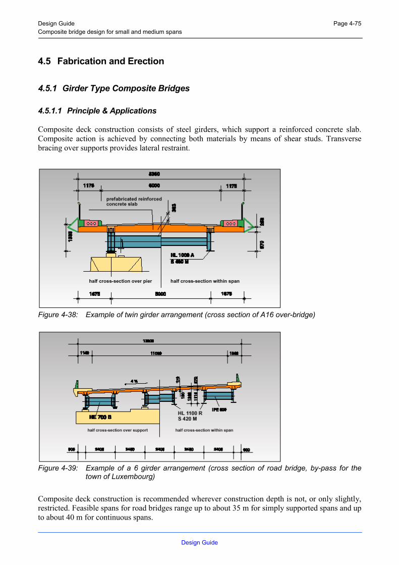
Design Guide Composite bridge design for small and medium spans
Design Guide
Page 4-75
4.5 Fabrication and Erection
4.5.1 Girder Type Composite Bridges
4.5.1.1 Principle & Applications
Composite deck construction consists of steel girders, which support a reinforced concrete slab. Composite action is achieved by connecting both materials by means of shear studs. Transverse bracing over supports provides lateral restraint.
Figure 4-38: Example of twin girder arrangement (cross section of A16 over-bridge)
Figure 4-39: Example of a 6 girder arrangement (cross section of road bridge, by-pass for the town of Luxembourg)
Composite deck construction is recommended wherever construction depth is not, or only slightly, restricted. Feasible spans for road bridges range up to about 35 m for simply supported spans and up to about 40 m for continuous spans.

Design Guide Composite bridge design for small and medium spans
Design Guide
Page 4-76
4.5.1.2 Static system
For a narrow deck, two main girders are required. When the deck is wider or when construction depth is restricted, more than two girders will be needed.
Girders of single span bridges are simply supported on the abutments. Multiple span bridges are designed either as successive simply supported or as continuous structures.
Continuous girders are statically better suited: bending moments are lower and deflections are smaller. In addition they offer a major constructional advantage: the number of bearings and expansion joints, which cause high costs by the need for regular maintenance, is reduced.
Depending on the overall bridge length and transport conditions the beams may be erected as unspliced pieces (delivered ex works in lengths up to 34 m or in exceptional cases up to 45 m) or site splicing will be necessary. In the latter base both splicing by butt-welding and by bolting (high strength friction grip bolts) have proved successful. A newly developed method consists in connecting the beams to a concrete cross girder through end plates and additional slab.
Figure 4-40: Railway bridge over the A23 motorway in Fretin, France. Four-span bridge with spans of 16,9 - 21,9 -23,0 - 17,8. The two continuous main girders and the bracings within spans are rolled beams; the cross beams at supports are made of reinforced concrete.

Design Guide Composite bridge design for small and medium spans
Design Guide
Page 4-77
4.5.1.3 Cambering and bending of main girders
Girders are cambered to compensate for deflections under permanent loads. Additional bending may be required to form the girders to the shape of the longitudinal profile. If the bridge is horizon-tally curved bending along the weak axis may be necessary. Both cambering and bending are carried out in the rolling mill on a press.
4.5.1.4 Surface Treatment
In addition to the significant aesthetic function surface treatment has to provide an effective protection against corrosion.
The following are conditions for a durable protection:
- careful surface preparation
- controlled application of the protective coating
- regular inspection during the life of the bridge and immediate repair of any damage.
Over the last few years, much progress has been made with respect to paint formulations, their application, their durability and their environmental friendliness. In general, modern coating systems last for at least 20 years before major maintenance.
Figure 4-41: Example of protective treatment for composite decks
The choice of a suitable system and the correct application are essential for effectiveness and durability. The available protective systems include the following:
- painting
- metal spraying
- hot-dip galvanizing
- galvanizing + painting (duplex system)
A number of aspects have to be considered for the choice of the appropriate system: type and expected life of the bridge, local climate and other environmental site conditions, constraints

Design Guide Composite bridge design for small and medium spans
Design Guide
Page 4-78
relating to maintenance, possibilities of surface preparation and painting, metal spaying or galvanizing at workshop, and feasibility of applying the final coating on site.
Steel components which are encased in concrete do not require coating. However transition zones must be carefully designed.
It is recommended to carry out as much of the surface treatment as possible in the controlled environment of a workshop. Usually only the finishing coat is applied after erection on site. Here, rolled beams can offer the advantage of already being coated with the required systems in the rolling mill.
4.5.1.5 Steel grades
Steel with a yield strength of 355 N/mm2 (S 355) and more recently of 460 N/mm2 (S 460), are used primarily. With the latter type, special attention should be paid to the stiffness requirements. The use of S 460 high-strength steel in place of the more traditional S 355 results in a substantial reduction in weight and corresponding savings in material costs. Fabrication costs are also lower, with a full butt joint, for example, the weld volume is considerably reduced.
The use of fine grain structural steel is particularly advantageous: for example, grade S 355 M or grade S 460 M in accordance with EN 10113-3.
Shapes made from these low alloy fine-grained steel are produced using a thermo-mechanical rolling process with an increased cooling rate and subsequent self-tempering. These grades demonstrate excellent toughness at low temperatures and are characterised by their outstanding weldability. Due to the low carbon equivalent value, pre-heating is not required before flame cutting and welding.
Figure 4-42: Composite road bridges. Structural steel weight per square meter of deck area.
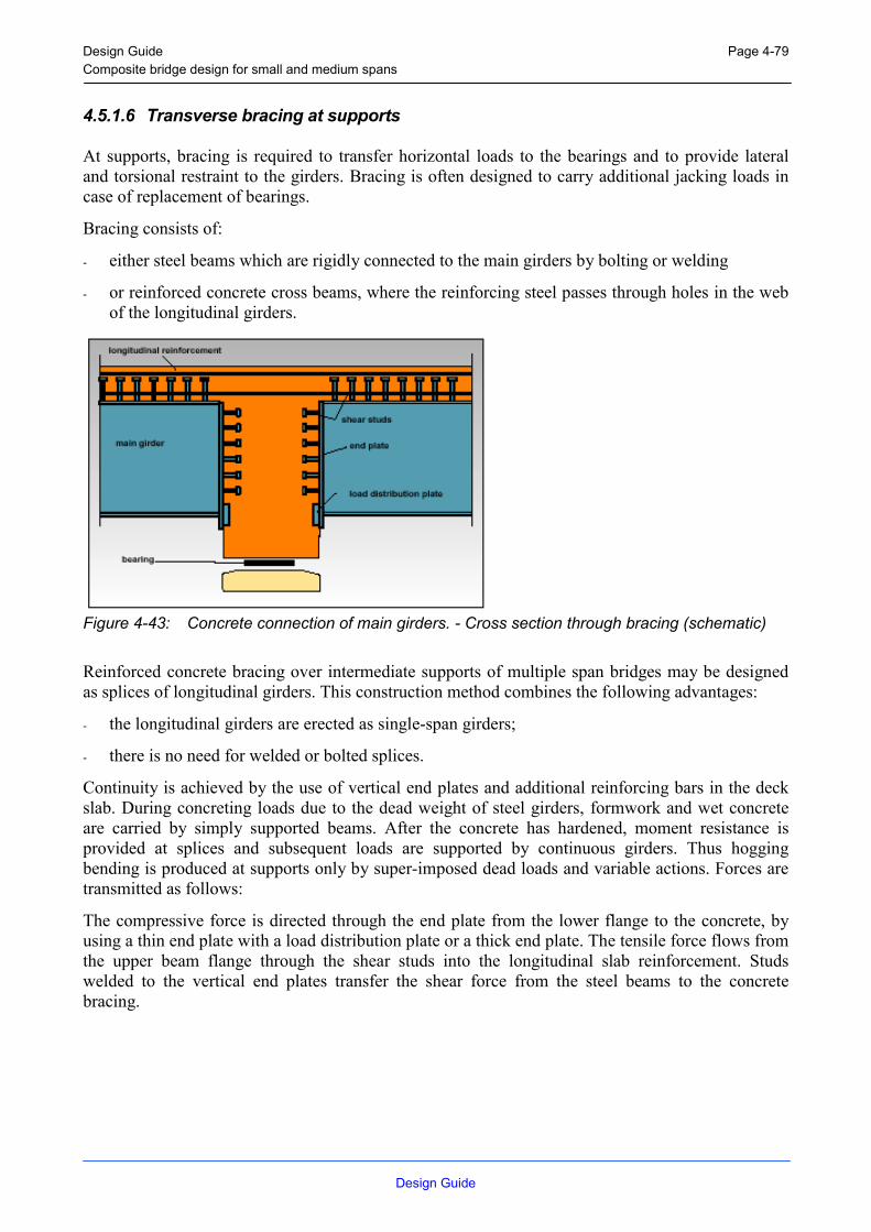
Design Guide Composite bridge design for small and medium spans
Design Guide
Page 4-79
4.5.1.6 Transverse bracing at supports
At supports, bracing is required to transfer horizontal loads to the bearings and to provide lateral and torsional restraint to the girders. Bracing is often designed to carry additional jacking loads in case of replacement of bearings.
Bracing consists of:
- either steel beams which are rigidly connected to the main girders by bolting or welding
- or reinforced concrete cross beams, where the reinforcing steel passes through holes in the web of the longitudinal girders.
Figure 4-43: Concrete connection of main girders. - Cross section through bracing (schematic)
Reinforced concrete bracing over intermediate supports of multiple span bridges may be designed as splices of longitudinal girders. This construction method combines the following advantages:
- the longitudinal girders are erected as single-span girders;
- there is no need for welded or bolted splices.
Continuity is achieved by the use of vertical end plates and additional reinforcing bars in the deck slab. During concreting loads due to the dead weight of steel girders, formwork and wet concrete are carried by simply supported beams. After the concrete has hardened, moment resistance is provided at splices and subsequent loads are supported by continuous girders. Thus hogging bending is produced at supports only by super-imposed dead loads and variable actions. Forces are transmitted as follows:
The compressive force is directed through the end plate from the lower flange to the concrete, by using a thin end plate with a load distribution plate or a thick end plate. The tensile force flows from the upper beam flange through the shear studs into the longitudinal slab reinforcement. Studs welded to the vertical end plates transfer the shear force from the steel beams to the concrete bracing.

Design Guide Composite bridge design for small and medium spans
Design Guide
Page 4-80
Figure 4-44: Concrete connection of main girders. - A pair of girders are lifted by crane into the recesses of the prefabricated formwork.
4.5.1.7 Intermediate transverse bracing
Vertical loads are laterally distributed by the means of the deck slab. Bracing within the span is needed to stabilise the girders, but does not participate in load distribution.
During construction, bracing prevents girders from lateral torsional buckling in sagging moment regions. After hardening of the concrete, the slab takes over this stabilizing action and bracing may be removed. With continuous girders, lateral buckling of the lower compression flange in hogging moment regions must be avoided. This is achieved using the bracing at the supports and, if needed, additional intermediate permanent bracing.
Figure 4-45: New public transport system in Oberhausen, Germany. –Crossing the DB railway line.
4.5.1.8 Deck slab
The deck consists of a non prestressed concrete slab with longitudinal and transverse reinforcement. Longitudinal reinforcement of continuous decks must be specially designed for crack width control.
Hogging moments of two and three span bridges may be reduced by lowering the structure at inter-mediate supports after concrete hardening.

Design Guide Composite bridge design for small and medium spans
Design Guide
Page 4-81
4.5.1.9 Bearings and supports
In general, simple elastomeric bearing pads are used with composite bridges. The advantage of the low construction weight of composite construction results in smaller dimensions for the sub-structure, including abutments, piers and foundations (in particular, pile foundations). The resulting savings in construction costs are characteristic for this construction method.
4.5.1.10 Fabrication, transport and erection
Fabrication consists of the finishing of the rolled beams, i.e. cutting to length, drilling, cambering or bending about the strong axis and, if required, about the weak axis, welding of shear studs and bearing plates, surface preparation and application of a corrosion protection system. These operations can be carried out at the rolling mill's finishing department in a both cost effective and time-saving process. Alternatively the work can also be carried out fully or partially in a steel fabricators' workshop.
The ready-to-erect girders are transported to the construction site by rail or by lorry. The single components are relatively light and therefore only low capacity lifting equipment is required on site.
Figure 4-46: Railway bridge over the A23 motorway in Fretin, France. –Launching of the steel structure and assembled formwork.
The girders are often pre-assembled in pairs in order to get erection units with increased stability. The girders or pairs of girders are lifted into final position by mobile cranes. Alternatively elements are assembled in a nearly area and subsequently launched.
The low masses of steel components enable rapid assembly of the structure. In most cases, there is no need for temporary supports. When the routes crossed are in service, disruption to traffic can be kept to a minimum, especially if works are scheduled during off-peak hours.

Design Guide Composite bridge design for small and medium spans
Design Guide
Page 4-82
4.5.1.11 In-situ Concrete Slab
The concrete slab can be cast in situ either on reusable formwork, or on precast concrete planks or profiled steel sheeting.
Figure 4-47: Precast reinforced concrete panels used for permanent formwork.
If certain conditions relating to construction and reinforcement are complied with, the precast planks contribute to carrying loads in the transverse direction, together with in situ concrete. For cantilever parts, traditional formwork is generally used, with supports attached to the edge beams.
Figure 4-48: Example of formwork support for cantilever part of slab.
4.5.1.12 Prefabricated Slab
As an alternative to in-site concreting, precast deck elements can be used. The main advantage of this method consist in the reduction of the number of site operations and a substantial saving in the construction time.
With twin girder - type bridges, the precast elements span the full width of the bridge as a single component. To allow connection with steel girders, slab elements have pockets for shear studs.
The prefabricated elements are placed in a mortar bedding on the girder flanges. Alternatively support may be designed with a small gap between flange and slab which is later filled in with grout.

Design Guide Composite bridge design for small and medium spans
Design Guide
Page 4-83
Figure 4-49: Prefabricated slab. Example of transverse joint detailing:
Figure 4-50: Deck units before concreting of pockets and joints
Consequently transverse joints and pockets are filled with concrete to connect the slab to the steel structure.
Hogging moments in continuous span girders can be reduced by lowering (jacking) the structure or intermediate supports after hardening of the concrete. The slab is prestressed longitudinally.

Design Guide Composite bridge design for small and medium spans
Design Guide
Page 4-84
4.5.2 Prestressed Composite Girders
4.5.2.1 Principle & Applications
When a rolled beam is bent the tension flange is elastically stressed. In this state it is encased in concrete. Shear connections are provided for composite action.
After hardening of the concrete, bending is released. The concrete part is thus compressed –it is prestressed.
After erection on site the other flange is connected to the concrete slab. By this procedure double composite action is given.
Figure 4-51: Fabrication of prestressed composite girder
A two-fold aim is achieved:
- the concrete slab increases the bending capacity and stiffness of the girder;
- under service load pre-compression stress in the concrete of the lower flange is reduced, but not totally. Thus no cracking occurs; concrete of the lower flange increases the flexural stiffness and reduces deflection.
Prestressed composite girders have:
- a very high moment capacity; they are suited to the construction of bridges carrying heavy loads, in particular railway bridges;
- a very high stiffness; deflections under service loading are small.
Due to these properties, prestressed girders are particularly suited to structures when the available construction depth is highly restricted. The slenderness ratio value (ratio of the span divided by the structural depth) may reach 45 for road bridges.
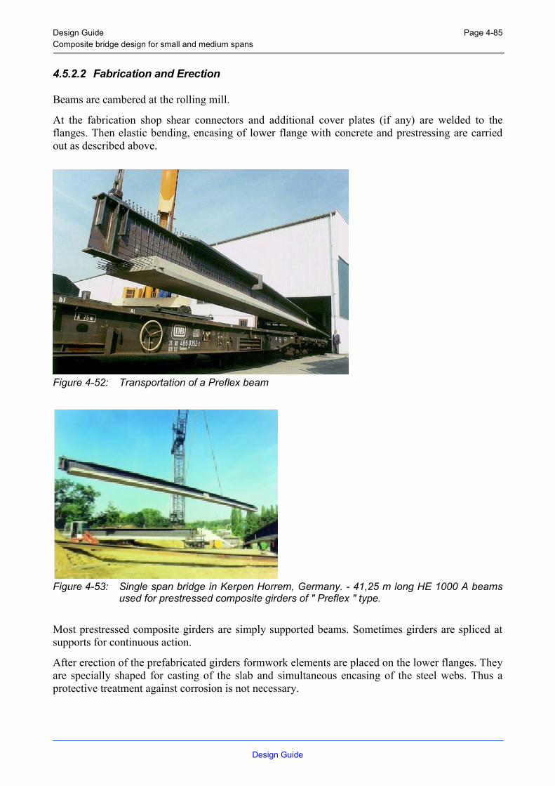
Design Guide Composite bridge design for small and medium spans
Design Guide
Page 4-85
4.5.2.2 Fabrication and Erection
Beams are cambered at the rolling mill.
At the fabrication shop shear connectors and additional cover plates (if any) are welded to the flanges. Then elastic bending, encasing of lower flange with concrete and prestressing are carried out as described above.
Figure 4-52: Transportation of a Preflex beam
Figure 4-53: Single span bridge in Kerpen Horrem, Germany. - 41,25 m long HE 1000 A beams used for prestressed composite girders of " Preflex " type.
Most prestressed composite girders are simply supported beams. Sometimes girders are spliced at supports for continuous action.
After erection of the prefabricated girders formwork elements are placed on the lower flanges. They are specially shaped for casting of the slab and simultaneous encasing of the steel webs. Thus a protective treatment against corrosion is not necessary.

Design Guide Composite bridge design for small and medium spans
Design Guide
Page 4-86
If particularly high loads are to be carried (for example railway loads) prestressed composite girders may be arranged side by side. No formwork is needed. By encasing in concrete girders are integrated into a massive slab.
4.5.3 Lateral torsional buckling of the beams during erection
The erection phase may involve very different procedures. The recommendations below are limited to the stage of casting the concrete slab. It is assumed that the formwork does not provide lateral restraint for the top flange. If the formwork is designed to brace the top flange the recommendations in 3.2.6 are applicable.
For continuous bridges the concrete is usually cast in stages. The first stage is usually casting the sagging region of an end span, see Figure 3-14. This creates a high sagging bending moment while the top flange is still unsupported, which may be critical for lateral torsional buckling. Next stage will be casting the sagging region of the adjacent span. If the beam is symmetric this stage is less critical than the previous but if there is no symmetry also this stage may need to be checked. The third stage would be to cast the remaining part over the pier. This stage creates the maximum hogging bending during erection but this is not likely to be critical. Worse cases will occur during operation.
4.5.3.1 Girders with intermediate cross braces
The cross braces will prevent twisting of the beams. Although the lateral displacement is not prevented the only possible lateral buckling mode is one with nodes at the locations of the cross braces. For this case the recommendations in 5.5.2.4 of EC3-2 are applicable. During casting it is usually the top flange that has to be checked. The bottom flange will normally be no problem.
4.5.3.2 Girders without cross braces other than at support
The beam will be free to buckle laterally over the whole length. It is a load case that gives maximum sagging moment that will be critical, like that in Figure 3-14. Unless the possible rotational restraint from the formwork is investigated it is recommended to assume the load to be applied at the top flange. For simple cases critical loads can be found in StBk-K2 (Swedish handbook, English or German to be added). It covers simply supported and continuous beams with uniform load. Usually it is assumed that the flanges are simply supported for lateral bending at the support in such solutions. In this case it may be worth considering the continuity also in lateral direction. The best recommendation for finding the critical load is to use a computer simulation.
Having found the critical load, the design according to 5.5.2 of EC3-2 is straightforward.

Design Guide Composite bridge design for small and medium spans
Design Guide
Page 4-87
Figure 4-54: Typical load case during casting of the concrete deck.
Reference: Kommentarer till Stålbyggnadsnorm 70, StBK-K2. Bulletin nr. 100. 1973. Division of Building Statics and Structural Engineering, Royal Institute of Technology, Stocholm, Sweden

Design Guide Composite bridge design for small and medium spans
Design Guide
Page 5-88
5 EXAMPLES In this chapter two examples are carried out: - 5.1 Two-span bridge using partially prefabricated elements - 5.2 Simple bridge using fully prefabricated elements The design examples are performed using the ANNEX A: Software CBD. Therefore the user interfaces and a list of input data are added. Tender drawings to the examples are added in ANNEX B: Tender Drawings.

Design Guide Composite bridge design for small and medium spans
Design Guide
Page 5-89
5.1 Composite Bridge with Partially Prefabricated Elements
5.1.1 Static System
Figure 5-1: Static system
5.1.2 Concrete Plate
Figure 5-2: Concrete Plate

Design Guide Composite bridge design for small and medium spans
Design Guide
Page 5-90
5.1.3 Hybrid Girder (inner beam)
Figure 5-3: Hybrid girder (inner beam)
5.1.4 Hybrid Girder (outer beam)
Figure 5-4: Hybrid girder (outer beam)

Design Guide Composite bridge design for small and medium spans
Design Guide
Page 5-91
5.1.5 Shear Connectors
Figure 5-5: Shear connectors
5.1.6 Loads on the Structure
Figure 5-6: Loads on the structure

Design Guide Composite bridge design for small and medium spans
Design Guide
Page 5-92
5.1.6.1 Loads on an Inner Beam
Table 5-1: Loads on the inner beam
Loads Distributed Start point End point Point Load Place Moment Place dT [To > Tu][kN/m] [m] [m] [kN] [m] [kNm] [m] [K]
Casting Loads 2,00 0,00 52,00 - - - - -2,00 8,90 11,90 - - - - -
Permanent Loads 6,46 0,00 52,00 - - - - -max Traffic Loads - - - 228,00 9,80 - - -
- - - 228,00 11,00 - - -1,00 0,00 52,00 - - - - -
min Traffic Loads - - - 228,00 14,22 - - -- - - 228,00 15,42 - - -
1,00 0,00 52,00 - - - - -Breaking Loads - - - 900,00 52,00 419,00 26,00 -
Temperature Loads - - - - - - - 10,00Temperature Loads - - - - - - - -7,00
5.1.6.2 Loads on an Outer Beam
Table 5-2: Loads on the outer beam
Loads Distributed Start point End point Point Load Place Moment Place dT [To > Tu][kN/m] [m] [m] [kN] [m] [kNm] [m] [K]
Casting Loads 1,00 0,00 52,00 - - - - -1,00 8,90 11,90 - - - - -
Permanent Loads 16,03 0,00 52,00 - - - - -max Traffic Loads - - - 138,00 9,80 - - -
- - - 138,00 11,00 - - -0,60 0,00 52,00 - - - - -
min Traffic Loads - - - 138,00 14,22 - - -- - - 138,00 15,42 - - -
0,60 0,00 52,00 - - - - -Breaking Loads - - - 900,00 52,00 419,00 26,00 -
Temperature Loads - - - - - - - 10,00Temperature Loads - - - - - - - -7,00

Design Guide Composite bridge design for small and medium spans
Design Guide
Page 5-93
5.1.7 Settings for the Calculation
Figure 5-7: Settings for the calculation
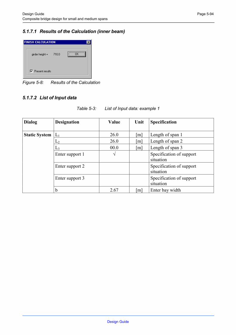
Design Guide Composite bridge design for small and medium spans
Design Guide
Page 5-94
5.1.7.1 Results of the Calculation (inner beam)
Figure 5-8: Results of the Calculation
5.1.7.2 List of Input data
Table 5-3: List of Input data: example 1
Dialog Designation Value Unit Specification
L1 26.0 [m] Length of span 1 L2 26.0 [m] Length of span 2 L3 00.0 [m] Length of span 3 Enter support 1 √ Specification of support
situation Enter support 2 Specification of support
situation Enter support 3 Specification of support
situation
Static System
b 2.67 [m] Enter bay width

Design Guide Composite bridge design for small and medium spans
Design Guide
Page 5-95
hc 300 [mm] Height of concrete plate hp 100 [mm] Height of pre-fabricated
element As, lat / Ac 0.5 % Degree of lateral reinforcement As1 (field) 187 cm²/m Upper reinforcement area of
field section zs1 (field) 110 [mm] Distance of upper reinforcement
from the top of the concrete plate
As2 (field) 0 cm²/m Lower reinforcement area of field section
zs2 (field) 0 [mm] Distance of lower reinforcement from the top of the concrete plate
As1 (support) 333 cm²/m Upper reinforcement area of support section
zs1 (support) 96 [mm] Distance of upper reinforcement from the top of the concrete plate
As2 (support) 0 cm²/m Lower reinforcement area of support section
zs2 (support) 0 [mm] Distance of lower reinforcement from the top of the concrete plate
Concrete class C 40 / 50
Concrete Plate
Reinforcement strength
BSt 500 S

Design Guide Composite bridge design for small and medium spans
Design Guide
Page 5-96
Kind of fabrication Plate section Rolled section or plate section Kind of profile - Specify the rolled profile type Steel girder strength - Specify the steel strength of
rolled profile Plate section hybrid Enter kind of plate layout Steel strength flange S 460 Steel strength of the flange Steel strength web S 355 Steel strength of the web Reduction of steel strength
√ Reduction of steel strength according to the thickness of the plate
s 9 [mm] Web thickness b1 (field) 300 [mm] Upper flange width of field
section b2 (field) 400 [mm] Lower flange width of field
section t1 (field) 21 [mm] Upper flange thickness of field
section t2 (field) 34 [mm] Lower flange thickness of field
section b1 (support) 300 [mm] Upper flange width of support
section b2 (support) 400 [mm] Lower flange width of support
section t1 (support) 21 [mm] Upper flange thickness of
support section
Girder
t2 (support) 34 [mm] Lower flange thickness of support section
Studs active Select studs as shear connectorsS 235 Use S 235 for studs S 460 √ Use S 460 for studs CUSTOM Use a customised material for
studs fu - [N/mm²] Ultimate strain fy - [N/mm²] Yield strength Diameter d = 16 mm Diameter of studs Diameter d = 19 mm Diameter of studs Diameter d = 22 mm Diameter of studs Diameter d = 25 mm √ Diameter of studs height h = 200 [mm] Height of studs alternative shear connectors
select Use an alternative shear connector
Connectors
PRd [kN/m] Bearing resistance of the alternative shear connector

Design Guide Composite bridge design for small and medium spans
Design Guide
Page 5-97
Load cases Casting Select load case x [1] – [8] 0 [m] Distance of point load 1 – 8
from left support F [1] – [8] 0 [kN] Magnitude of point load 1 - 8 x0 [1] 0 [m] Distance starting point of
distributed load 1 from left support
q0 [1] 2 [kN/m] Magnitude of the distributed load 1 at starting point
x1 [1] 52 [m] Distance end point of distributed load 1 from left support
q1 [1] 2 [kN/m] Magnitude of distributed load 1 at end point
x0 [2] 8.9 [m] Distance starting point of distributed load 2 from left support
q0 [2] 2 [kN/m] Magnitude of the distributed load 2 at starting point
x1 [2] 11.9 [m] Distance end point of distributed load 2 from left support
q1 [2] 2 [kN/m] Magnitude of distributed load 2 at end point
x0 [3], [4] 0 [m] Distance starting point of distributed load 3, 4 from left support
q0 [3], [4] 0 [kN/m] Magnitude of the distributed load 3, 4 at starting point
x1 [3], [4] 0 [m] Distance end point of distributed load 3, 4 from left support
Loads
q1 [3], [4] 0 [kN/m] Magnitude of distributed load 3, 4 at end point

Design Guide Composite bridge design for small and medium spans
Design Guide
Page 5-98
Load cases Permanent Select load case x [1] – [8] 0 [m] Distance of point load 1 - 8
from left support F [1] – [8] 0 [kN] Magnitude of point load 1 - 8 x0 [1] 0 [m] Distance starting point of
distributed load 1 from left support
q0 [1] 6.46 [kN/m] Magnitude of the distributed load 1 at starting point
x1 [1] 52 [m] Distance end point of distributed load 1 from left support
q1 [1] 6.46 [kN/m] Magnitude of distributed load 1 at end point
x0 [2], [4] 0 [m] Distance starting point of distributed load 2, 3& 4 from left support
q0 [2], [4] 0 [kN/m] Magnitude of the distributed load 2, 3& 4 at starting point
x1 [2], [4] 0 [m] Distance end point of distributed load 2, 3& 4 from left support
Loads
q1 [2], [4] 0 [kN/m] Magnitude of distributed load 2, 3 & 4 at end point

Design Guide Composite bridge design for small and medium spans
Design Guide
Page 5-99
Load cases Traffic [max] Select load case x [1] 9.8 [m] Distance of point load 1 from
left support F [1] 228 [kN] Magnitude of point load 1 x [2] 11.0 [m] Distance of point load 2 from
left support F [2] 228 [kN] Magnitude of point load 2 x [3] – [8] 0 [m] Distance of point load 3 – 8
from left support F [3] – [8] 0 [kN] Magnitude of point load 3 - 8 x0 [1] 0 [m] Distance starting point of
distributed load 1 from left support
q0 [1] 1.0 [kN/m] Magnitude of the distributed load 1 at starting point
x1 [1] 52 [m] Distance end point of distributed load 1 from left support
q1 [1] 1.0 [kN/m] Magnitude of distributed load 1 at end point
x0 [2], [4] 0 [m] Distance starting point of distributed load 2, 3& 4 from left support
q0 [2], [4] 0 [kN/m] Magnitude of the distributed load 2, 3& 4 at starting point
x1 [2], [4] 0 [m] Distance end point of distributed load 2, 3& 4 from left support
Loads
q1 [2], [4] 0 [kN/m] Magnitude of distributed load 2, 3 & 4 at end point

Design Guide Composite bridge design for small and medium spans
Design Guide
Page 5-100
Load cases Traffic [min] Select load case x [1] 14.22 [m] Distance of point load 1 from
left support F [1] 228 [kN] Magnitude of point load 1 x [2] 15.42 [m] Distance of point load 2 from
left support F [2] 228 [kN] Magnitude of point load 2 x [3] – [8] 0 [m] Distance of point load 3 – 8
from left support F [3] – [8] 0 [kN] Magnitude of point load 3 - 8 x0 [1] 0 [m] Distance starting point of
distributed load 1 from left support
q0 [1] 1.0 [kN/m] Magnitude of the distributed load 1 at starting point
x1 [1] 52 [m] Distance end point of distributed load 1 from left support
q1 [1] 1.0 [kN/m] Magnitude of distributed load 1 at end point
x0 [2], [4] 0 [m] Distance starting point of distributed load 2, 3& 4 from left support
q0 [2], [4] 0 [kN/m] Magnitude of the distributed load 2, 3& 4 at starting point
x1 [2], [4] 0 [m] Distance end point of distributed load 2, 3& 4 from left support
Loads
q1 [2], [4] 0 [kN/m] Magnitude of distributed load 2, 3 & 4 at end point
Load cases Breaking Select load case x [1] 26.0 [m] Distance of moment 1 from left
support F [1] 419 [kNm] Magnitude of moment 1 x [2] – [8] 0 [m] Distance of moment 2 – 4 from
left support F [2] – [8] 0 [kNm] Magnitude of moment 2 - 4
Loads
Hx 0 [kN] Horizontal load due to breaking or acceleration
Load cases Temperature Select load case dT [ To > Tu ] 10 [K] Top of concrete warmer than
bottom concrete
Loads
dT [ Tu > To ] 7 [K] Top of concrete colder than bottom concrete

Design Guide Composite bridge design for small and medium spans
Design Guide
Page 5-101
Constr. Sit. 1 Take construction situation 1
into account x 15 % L Distance of the hinge in
construction sit. 1 Right side of support Place of the hinge referring to
the column Left side of support √ Place of the hinge referring to
the column Constr. Sit. 2 √ Take construction situation 2
into account Constr. Sit. 3 √ Take construction situation 3
into account Constr. Sit. 4 √ Take construction situation 4
into account Max deflection √ Perform deflection check L / 200 Deflection limit Moment distribution √ Take moment distribution into
account Creep √ Take creep into account Shrinkage √ Take shrinkage into account
Settings
Safety factors Germany Specify set of combination factors for various countries
Combination factors (ULS)
ψ (Casting) 1.0 Combination factor for casting loads (ULS)
ψ (Traffic TS) 1.0 Combination factor for single traffic loads (ULS)
ψ (Traffic UDL) 0.4 Combination factor for uniformly distributed traffic loads (ULS)
ψ (Breaking) 0.7 Combination factor for breaking loads (ULS)
ψ (Temperature) 0.6 Combination factor for temperature loads (ULS)
Combination factors (SLS)
ψ (Casting) 1.0 Combination factor for casting loads (SLS)
ψ (Traffic TS) 1.0 Combination factor for single traffic loads (SLS)
ψ (Traffic UDL) 0.4 Combination factor for uniformly distributed traffic loads (SLS)
ψ (Breaking) 0.7 Combination factor for breaking loads (SLS)
ψ (Temperature) 0.6 Combination factor for temperature loads (SLS)

Design Guide Composite bridge design for small and medium spans
Design Guide
Page 5-102
5.1.7.3 Partial safety factors [NAD]
Table 5-4: Partial safety factors
µg µq µM0 µM1 νvec µc µs µv 1.35 1.50 1.10 1.10 0.80 1.50 1.15 1.25

Design Guide Composite bridge design for small and medium spans
Design Guide
Page 5-103
5.1.7.4 Cross Section
5.1.7.4.1 Cross Section over support
Section Units Value Steel beam Iyy [cm4] 236492 Wc,o [cm³] 0 Wc,u [cm³] 0 Wst,o [cm³] - 5213 Wst,u [cm³] 8879Partially composite slab Short term Iyy [cm4] 982197 W0,c,o [cm³] -250536 W0,c,u [cm³] -435813 W0,st,o [cm³] -72636 W0,st,u [cm³] 16796Long term Iyy [cm4] 753360 Wb,c,o [cm³] -506032 Wb,c,u [cm³] -565653 Wb,st,o [cm³] -24445 Wb,st,u [cm³] 18293Shrinkage Iyy [cm4] 843296 Ws,c,o [cm³] -354499 Ws,c,u [cm³] -478000 Ws,st,o [cm³] -35142 Ws,st,u [cm³] 17568Fully composite slab Short term Iyy [cm4] 1332023 W0,c,o [cm³] -473156 W0,c,u [cm³] 609675 W0,st,o [cm³] 101613 W0,st,u [cm³] 15651Long term Iyy [cm4] 1182758 Wb,c,o [cm³] -1105768 Wb,c,u [cm³] -30137254 Wb,st,o [cm³] 155419 Wb,st,u [cm³] 14857Long term Iyy [cm4] 1241473 Ws,c,o [cm³] -598816 Ws,c,u [cm³] 3109858 Ws,st,o [cm³] 132595 Ws,st,u [cm³] 15259

Design Guide Composite bridge design for small and medium spans
Design Guide
Page 5-104
5.1.7.4.2 Cross Section in the field
Section Units Value Steel beam Iyy [cm4] 236492 Wc,o [cm³] 0 Wc,u [cm³] 0 Wst,o [cm³] - 5213 Wst,u [cm³] 8879Partially composite slab Short term Iyy [cm4] 863940 W0,c,o [cm³] -220372 W0,c,u [cm³] -383341 W0,st,o [cm³] -63890 W0,st,u [cm³] 14774Long term Iyy [cm4] 638070 Wb,c,o [cm³] -422298 Wb,c,u [cm³] -471327 Wb,st,o [cm³] -20859 Wb,st,u [cm³] 15409Shrinkage Iyy [cm4] 725756 Ws,c,o [cm³] -304395 Ws,c,u [cm³] -410159 Ws,st,o [cm³] -30313 Ws,st,u [cm³] 15102Fully composite slab Short term Iyy [cm4] 1270879 W0,c,o [cm³] -395312 W0,c,u [cm³] 711928 W0,st,o [cm³] 118655 W0,st,u [cm³] 15365Long term Iyy [cm4] 1089774 Wb,c,o [cm³] -848025 Wb,c,u [cm³] -4462591 Wb,st,o [cm³] 236949 Wb,st,u [cm³] 14227Long term Iyy [cm4] 1163055 Ws,c,o [cm³] -511810 Ws,c,u [cm³] 5718311 Ws,st,o [cm³] 159917 Ws,st,u [cm³] 14672

Design Guide Composite bridge design for small and medium spans
Design Guide
Page 5-105
5.1.8 Design
The effective width of the concrete plate beff = 2.67 [m]
The beam is rated into class 2 therefore the checks can be carried out plastically.
5.1.8.1 Bearing Resistance in the negative moment area
Steel beam: Vsd = 941.9 [kN]
Msd = 2688.4 [kNm]
The beam has to be restrained against torsional buckling during construction.
Fully Composite beam [t = 28d]: Vsd = 947.8 [kN]
Msd = 6464.0 [kNm]
Fully Composite beam [t = ∞d]: Vsd = 947.8 [kN]
Msd = 6039.5 [kNm]
5.1.8.2 Bearing Resistance in the positive moment area
Steel beam: Vsd = 941.9 [kN]
Msd = 2688.4 [kNm]
The beam has to be restrained against torsional buckling during construction.
Partially Composite beam: Vsd = 947.8 [kN]
Msd = 5115.0 [kNm]
Fully Composite beam [t = 28d]: Vsd = 947.8 [kN]
Msd = 6718.2 [kNm]
Fully Composite beam [t = ∞d]: Vsd = 947.8 [kN]
Msd = 6718.2 [kNm]

Design Guide Composite bridge design for small and medium spans
Design Guide
Page 5-106
5.1.8.3 Further Design Checks
The reinforcement diameter has to be smaller than 44 [mm] or the maximal distance between the reinforcement bars has to be smaller than 25 [cm] to satisfy the crack width design checks of the Eurocode.
The shear connectors have got a design resistance of Prd = 172 [kN].
The following criteria for the studs have to be satisfied:
- average welded bead diameter: dw > 1.25 d = 31.25 [mm]
- average welded bead height: hwm > 0.2 d = 5.00 [mm]
- minimum welded bead height: hw,min > 0.15 d = 3.75 [mm]
- minimum distance in direction of shear: emin > 5 d = 125.00 [mm]
- minimum distance vertical to direction of shear: emin > 2.5 d = 62.50 [mm]
If studs are not placed directly over the web, the diameter of the studs should be less than 22.5 [mm]
The following number of shear connectors have to be applied:
- 63 between support 1 and Mmax in span 1
- 148 between Mmax in span 1 and support 2
- 148 between support 2 and Mmax in span 2
- 64 between Mmax in span 2 and support 3
The deflection checks are satisfied for all spans.

Design Guide Composite bridge design for small and medium spans
Design Guide
Page 5-107
5.1.9 Results of the Calculation (outer beam)
5.1.9.1 Partial safety factors [NAD]
Table 5-5: Partial safety factors, example 1
µg Μq µM0 µM1 νvec µc µs µv 1.35 1.50 1.10 1.10 0.80 1.50 1.15 1.25

Design Guide Composite bridge design for small and medium spans
Design Guide
Page 5-108
5.1.9.2 Cross Section
5.1.9.2.1 Cross Section over support
Section Units Value Steel beam Iyy [cm4] 244539 Wc,o [cm³] 0 Wc,u [cm³] 0 Wst,o [cm³] - 5247 Wst,u [cm³] 9631Partially composite slab Short term Iyy [cm4] 1049331 W0,c,o [cm³] -255950 W0,c,u [cm³] -431275 W0,st,o [cm³] -71879 W0,st,u [cm³] 18281Long term Iyy [cm4] 797238 Wb,c,o [cm³] -517760 Wb,c,u [cm³] -576490 Wb,st,o [cm³] -24691 Wb,st,u [cm³] 20076Shrinkage Iyy [cm4] 895554 Ws,c,o [cm³] -361878 Ws,c,u [cm³] -481440 Ws,st,o [cm³] -35302 Ws,st,u [cm³] 19205Fully composite slab Short term Iyy [cm4] 1426104 W0,c,o [cm³] -492491 W0,c,u [cm³] 677709 W0,st,o [cm³] 112952 W0,st,u [cm³] 16852Long term Iyy [cm4] 1267461 Wb,c,o [cm³] -1149753 Wb,c,u [cm³] -16658990 Wb,st,o [cm³] 183827 Wb,st,u [cm³] 16065Long term Iyy [cm4] 1330145 Ws,c,o [cm³] -625557 Ws,c,u [cm³] 3858264 Ws,st,o [cm³] 152129 Ws,st,u [cm³] 16474

Design Guide Composite bridge design for small and medium spans
Design Guide
Page 5-109
5.1.9.2.2 Cross Section in the field
Section Units Value Steel beam Iyy [cm4] 244539 Wc,o [cm³] 0 Wc,u [cm³] 0 Wst,o [cm³] - 5247 Wst,u [cm³] 9631Partially composite slab Short term Iyy [cm4] 918828 W0,c,o [cm³] -224118 W0,c,u [cm³] -377638 W0,st,o [cm³] -62940 W0,st,u [cm³] 16007Long term Iyy [cm4] 670225 Wb,c,o [cm³] -428194 Wb,c,u [cm³] -475974 Wb,st,o [cm³] -20918 Wb,st,u [cm³] 16772Shrinkage Iyy [cm4] 765904 Ws,c,o [cm³] -308705 Ws,c,u [cm³] -410398 Ws,st,o [cm³] -30264 Ws,st,u [cm³] 16403Fully composite slab Short term Iyy [cm4] 1359545 W0,c,o [cm³] -411283 W0,c,u [cm³] 802386 W0,st,o [cm³] 133731 W0,st,u [cm³] 16546Long term Iyy [cm4] 1165103 Wb,c,o [cm³] -876617 Wb,c,u [cm³] -3982746 Wb,st,o [cm³] 312471 Wb,st,u [cm³] 15385Long term Iyy [cm4] 1244101 Ws,c,o [cm³] -532437 Ws,c,u [cm³] 9027632 Ws,st,o [cm³] 190309 Ws,st,u [cm³] 15841

Design Guide Composite bridge design for small and medium spans
Design Guide
Page 5-110
5.1.10 Design
The effective width of the concrete plate beff = 2.67 [m]
The beam is rated into class 2 therefore the checks can be carried out plastically.
5.1.10.1 Bearing Resistance in the negative moment area
Steel beam: Vsd = 941.6 [kN]
Msd = 2635.0 [kNm]
The beam has to be restrained against torsional buckling during construction.
Fully Composite beam [t = 28d]: Vsd = 945.2 [kN]
Msd = 6014.3 [kNm]
Fully Composite beam [t = ∞d]: Vsd = 945.2 [kN]
Msd = 5642.0 [kNm]
5.1.10.2 Bearing Resistance in the positive moment area
Steel beam: Vsd = 941.6 [kN]
Msd = 2635.0 [kNm]
The beam has to be restrained against torsional buckling during construction.
Partially Composite beam: Vsd = 945.2 [kN]
Msd = 5424.8 [kNm]
Fully Composite beam [t = 28d]: Vsd = 945.2 [kN]
Msd = 7087.0 [kNm]
Fully Composite beam [t = ∞d]: Vsd = 945.2 [kN]
Msd = 7087.0 [kNm]

Design Guide Composite bridge design for small and medium spans
Design Guide
Page 5-111
5.1.10.3 Further Design Checks
The reinforcement diameter has to be smaller than 44 [mm] or the maximal distance between the reinforcement bars has to be smaller than 25 [cm] to satisfy the crack width design checks of the Eurocode.
The shear connectors have a design resistance of Prd = 172 [kN].
The following criteria for the studs have to be satisfied:
- average welded bead diameter: dw > 1.25 d = 31.25 [mm]
- average welded bead height: hwm > 0.2 d = 5.00 [mm]
- minimum welded bead height: hw,min > 0.15 d = 3.75 [mm]
- minimum distance in direction of shear: emin > 5 d = 125.00 [mm]
- minimum distance vertical to direction of shear: emin > 2.5 d = 62.50 [mm]
If studs are not placed directly over the web, the diameter of the studs should be less
than 22.5 [mm]
The following number of shear connectors have to be applied:
- 66 between support 1 and Mmax in span 1
- 151 between Mmax in span 1 and support 2
- 151 between support 2 and Mmax in span 2
- 66 between Mmax in span 2 and support 3
The deflection checks are satisfied for all spans.

Design Guide Composite bridge design for small and medium spans
Design Guide
Page 5-112
5.2 Composite Bridge with Fully Prefabricated Elements
5.2.1 Static System
Figure 5-9: Static system
5.2.2 Concrete Plate
Figure 5-10: Concrete plate

Design Guide Composite bridge design for small and medium spans
Design Guide
Page 5-113
5.2.3 Girder in S 355
Figure 5-11: Girder in S 355
5.2.4 Shear Connectors
Figure 5-12: Shear connectors

Design Guide Composite bridge design for small and medium spans
Design Guide
Page 5-114
5.2.5 Loads on the Structure
Figure 5-13: Loads on the structure
5.2.5.1 Loads on Beam
Table 5-6: Loads on beam
Loads Distributed Start point End point Point Load Place Moment Place dT [To > Tu][kN/m] [m] [m] [kN] [m] [kNm] [m] [K]
Casting Loads 2,90 0,00 16,20 - - - - -2,90 6,60 9,60 - - - - -
Permanent Loads 30,80 0,00 16,20 - - - - -max Traffic Loads - - - 315,00 7,10 - - -
- - - 315,00 9,10 - - -1,20 0,00 16,20 - - - - -
min Traffic Loads - - - - - - - -- - - - - - - -
1,20 0,00 16,20 - - - - -Breaking Loads - - - 900,00 16,20 419,00 26,00 -
Temperature Loads - - - - - - - 10,00Temperature Loads - - - - - - - -7,00

Design Guide Composite bridge design for small and medium spans
Design Guide
Page 5-115
5.2.6 Settings for the Calculation
Figure 5-14: Settings for the calculation
5.2.7 Results of the Calculation
Figure 5-15: Results of the Calculation

Design Guide Composite bridge design for small and medium spans
Design Guide
Page 5-116
5.2.7.1 List of Input data
Table 5-7: List of Input data: example 1
Dialog Designation Value Unit Specification
L1 16.2 [m] Length of span 1 L2 00.0 [m] Length of span 2 L3 00.0 [m] Length of span 3 Enter support 1 √ Specification of support
situation Enter support 2 Specification of support
situation Enter support 3 Specification of support
situation
Static System
b 3.83 [m] Enter bay width
hc 260 [mm] Height of concrete plate hp [mm] Height of pre-fabricated
element As, lat / Ac 0.5 % Degree of lateral reinforcement As1 (field) 100 cm²/m Upper reinforcement area of
field section zs1 (field) 30 [mm] Distance of upper reinforcement
from the top of the concrete plate
As2 (field) 100 cm²/m Lower reinforcement area of field section
zs2 (field) 230 [mm] Distance of lower reinforcement from the top of the concrete plate
As1 (support) 100 cm²/m Upper reinforcement area of support section
zs1 (support) 30 [mm] Distance of upper reinforcement from the top of the concrete plate
As2 (support) 100 cm²/m Lower reinforcement area of support section
zs2 (support) 230 [mm] Distance of lower reinforcement from the top of the concrete plate
Concrete class C 40 / 50
Concrete Plate
Reinforcement strength
BSt 500 S
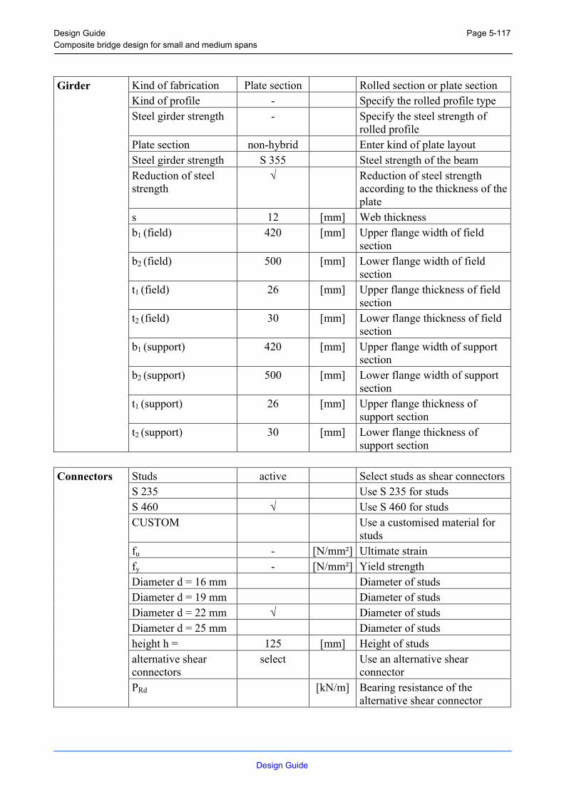
Design Guide Composite bridge design for small and medium spans
Design Guide
Page 5-117
Kind of fabrication Plate section Rolled section or plate section Kind of profile - Specify the rolled profile type Steel girder strength - Specify the steel strength of
rolled profile Plate section non-hybrid Enter kind of plate layout Steel girder strength S 355 Steel strength of the beam Reduction of steel strength
√ Reduction of steel strength according to the thickness of the plate
s 12 [mm] Web thickness b1 (field) 420 [mm] Upper flange width of field
section b2 (field) 500 [mm] Lower flange width of field
section t1 (field) 26 [mm] Upper flange thickness of field
section t2 (field) 30 [mm] Lower flange thickness of field
section b1 (support) 420 [mm] Upper flange width of support
section b2 (support) 500 [mm] Lower flange width of support
section t1 (support) 26 [mm] Upper flange thickness of
support section
Girder
t2 (support) 30 [mm] Lower flange thickness of support section
Studs active Select studs as shear connectorsS 235 Use S 235 for studs S 460 √ Use S 460 for studs CUSTOM Use a customised material for
studs fu - [N/mm²] Ultimate strain fy - [N/mm²] Yield strength Diameter d = 16 mm Diameter of studs Diameter d = 19 mm Diameter of studs Diameter d = 22 mm √ Diameter of studs Diameter d = 25 mm Diameter of studs height h = 125 [mm] Height of studs alternative shear connectors
select Use an alternative shear connector
Connectors
PRd [kN/m] Bearing resistance of the alternative shear connector

Design Guide Composite bridge design for small and medium spans
Design Guide
Page 5-118
Load cases Casting Select load case x [1] – [8] 0 [m] Distance of point load 1 – 8
from left support F [1] – [8] 0 [kN] Magnitude of point load 1 - 8 x0 [1] 0 [m] Distance starting point of
distributed load 1 from left support
q0 [1] 2.90 [kN/m] Magnitude of the distributed load 1 at starting point
x1 [1] 16.20 [m] Distance end point of distributed load 1 from left support
q1 [1] 2.90 [kN/m] Magnitude of distributed load 1 at end point
x0 [2] 6.60 [m] Distance starting point of distributed load 2 from left support
q0 [2] 2.90 [kN/m] Magnitude of the distributed load 2 at starting point
x1 [2] 9.60 [m] Distance end point of distributed load 2 from left support
q1 [2] 2.90 [kN/m] Magnitude of distributed load 2 at end point
x0 [3], [4] 0 [m] Distance starting point of distributed load 3, 4 from left support
q0 [3], [4] 0 [kN/m] Magnitude of the distributed load 3, 4 at starting point
x1 [3], [4] 0 [m] Distance end point of distributed load 3, 4 from left support
Loads
q1 [3], [4] 0 [kN/m] Magnitude of distributed load 3, 4 at end point

Design Guide Composite bridge design for small and medium spans
Design Guide
Page 5-119
Load cases Permanent Select load case x [1] – [8] 0 [m] Distance of point load 1 - 8
from left support F [1] – [8] 0 [kN] Magnitude of point load 1 - 8 x0 [1] 0 [m] Distance starting point of
distributed load 1 from left support
q0 [1] 30.80 [kN/m] Magnitude of the distributed load 1 at starting point
x1 [1] 16.20 [m] Distance end point of distributed load 1 from left support
q1 [1] 30.80 [kN/m] Magnitude of distributed load 1 at end point
x0 [2], [4] 0 [m] Distance starting point of distributed load 2, 3& 4 from left support
q0 [2], [4] 0 [kN/m] Magnitude of the distributed load 2, 3& 4 at starting point
x1 [2], [4] 0 [m] Distance end point of distributed load 2, 3& 4 from left support
Loads
q1 [2], [4] 0 [kN/m] Magnitude of distributed load 2, 3 & 4 at end point

Design Guide Composite bridge design for small and medium spans
Design Guide
Page 5-120
Load cases Traffic [max] Select load case x [1] 7.10 [m] Distance of point load 1 from
left support F [1] 315 [kN] Magnitude of point load 1 x [2] 9.10 [m] Distance of point load 2 from
left support F [2] 315 [kN] Magnitude of point load 2 x [3] – [8] 0 [m] Distance of point load 3 – 8
from left support F [3] – [8] 0 [kN] Magnitude of point load 3 - 8 x0 [1] 0 [m] Distance starting point of
distributed load 1 from left support
q0 [1] 1.20 [kN/m] Magnitude of the distributed load 1 at starting point
x1 [1] 16.20 [m] Distance end point of distributed load 1 from left support
q1 [1] 1.20 [kN/m] Magnitude of distributed load 1 at end point
x0 [2], [4] 0 [m] Distance starting point of distributed load 2, 3& 4 from left support
q0 [2], [4] 0 [kN/m] Magnitude of the distributed load 2, 3& 4 at starting point
x1 [2], [4] 0 [m] Distance end point of distributed load 2, 3& 4 from left support
Loads
q1 [2], [4] 0 [kN/m] Magnitude of distributed load 2, 3 & 4 at end point

Design Guide Composite bridge design for small and medium spans
Design Guide
Page 5-121
Load cases Traffic [min] Select load case x [1] – [8] 0 [m] Distance of point load 3 – 8
from left support F [1] – [8] 0 [kN] Magnitude of point load 3 - 8 x0 [1], [4] 0 [m] Distance starting point of
distributed load 2, 3& 4 from left support
q0 [1], [4] 0 [kN/m] Magnitude of the distributed load 2, 3& 4 at starting point
x1 [1], [4] 0 [m] Distance end point of distributed load 2, 3& 4 from left support
Loads
q1 [1], [4] 0 [kN/m] Magnitude of distributed load 2, 3 & 4 at end point
Load cases Breaking Select load case x [1] – [8] 0 [m] Distance of moment 2 – 4 from
left support F [1] – [8] 0 [kNm] Magnitude of moment 2 - 4
Loads
Hx 900 [kN] Horizontal load due to breaking or acceleration
Load cases Temperature Select load case dT [ To > Tu ] 10 [K] Top of concrete warmer than
bottom concrete
Loads
dT [ Tu > To ] 7 [K] Top of concrete colder than bottom concrete

Design Guide Composite bridge design for small and medium spans
Design Guide
Page 5-122
Constr. Sit. 1 √ Take construction situation 1
into account Constr. Sit. 2 √ Take construction situation 2
into account Max deflection √ Perform deflection check L / 200 Deflection limit Moment distribution √ Take moment distribution into
account Creep √ Take creep into account Shrinkage √ Take shrinkage into account
Settings
Safety factors Germany Specify set of combination factors for various countries
Combination factors (ULS)
ψ (Casting) 1.0 Combination factor for casting loads (ULS)
ψ (Traffic TS) 1.0 Combination factor for single traffic loads (ULS)
ψ (Traffic UDL) 0.4 Combination factor for uniformly distributed traffic loads (ULS)
ψ (Breaking) 0.7 Combination factor for breaking loads (ULS)
ψ (Temperature) 0.6 Combination factor for temperature loads (ULS)
Combination factors (SLS)
ψ (Casting) 1.0 Combination factor for casting loads (SLS)
ψ (Traffic TS) 1.0 Combination factor for single traffic loads (SLS)
ψ (Traffic UDL) 0.4 Combination factor for uniformly distributed traffic loads (SLS)
ψ (Breaking) 0.7 Combination factor for breaking loads (SLS)
ψ (Temperature) 0.6 Combination factor for temperature loads (SLS)
5.2.7.2 Partial safety factors [NAD]
Table 5-8: Partial safety factors, example 2
µg µq µM0 µM1 νvec µc µs µv 1.35 1.50 1.10 1.10 0.80 1.50 1.15 1.25

Design Guide Composite bridge design for small and medium spans
Design Guide
Page 5-123
5.2.7.3 Cross Section
5.2.7.3.1 Cross Section
Section Units Value Steel beam Iyy [cm4] 294703 Wc,o [cm³] 0 Wc,u [cm³] 0 Wst,o [cm³] - 7784 Wst,u [cm³] 9778Fully composite slab Short term Iyy [cm4] 1219257 W0,c,o [cm³] -376017 W0,c,u [cm³] 1117786 W0,st,o [cm³] 186298 W0,st,u [cm³] 16356Long term Iyy [cm4] 1070452 Wb,c,o [cm³] -1075968 Wb,c,u [cm³] -9888418 Wb,st,o [cm³] 494769 Wb,st,u [cm³] 15257Long term Iyy [cm4] 1129775 Ws,c,o [cm³] -611655 Ws,c,u [cm³] 3928389 Ws,st,o [cm³] 277575 Ws,st,u [cm³] 15676

Design Guide Composite bridge design for small and medium spans
Design Guide
Page 5-124
5.2.8 Design
The effective width of the concrete plate beff = 3.83 [m]
The beam is rated into class 2 therefore the checks can be carried out plastically.
5.2.8.1 Bearing Resistance
Steel beam: Vsd = 1395 [kN]
Msd = 2993 [kNm]
The beam has to be restrained against torsional buckling during construction.
Fully Composite beam [t = ∞d]: Vsd = 1395 [kN]
Msd = 6216 [kNm]
5.2.8.2 Further Design Checks
The reinforcement diameter has to be smaller than 44 [mm] or the maximal distance between the reinforcement bars has to be smaller than 25 [cm] to satisfy the crack width design checks of the Eurocode.
The shear connectors have a design resistance of Prd = 133 [kN].
The following criteria for the studs have to be satisfied:
- average welded bead diameter: dw > 1.25 d = 27.50 [mm]
- average welded bead height: hwm > 0.2 d = 4.40 [mm]
- minimum welded bead height: hw,min > 0.15 d = 3.30 [mm]
- minimum distance in direction of shear: emin > 5 d = 110.00 [mm]
- minimum distance vertical to direction of shear: emin > 2.5 d = 55.00 [mm]
If studs are not placed directly over the web, the diameter of the studs should be less than 30 [mm]
The following number of shear connectors have to be applied:
- 81 between support 1 and Mmax
- 147 between Mmax and support 2
The deflection checks are satisfied for all spans.

Design Guide Composite bridge design for small and medium spans
Design Guide
Page 5-125

Design Guide Composite bridge design for small and medium spans
Design Guide
Page 5-126

Design Guide Composite bridge design for small and medium spans
Design Guide
Page 1
ANNEX A: SOFTWARE CBD
It is possible to download the Software CBD (Composite Bridge Design) under the following homepage: http://www.stb.rwth-aachen.de/Projekte/ECSC/CompBridges/index.html

Design Guide Composite bridge design for small and medium spans
Design Guide
Page 2

Design Guide Composite bridge design for small and medium spans
Design Guide
Page 3
ANNEX B: TENDER DRAWINGS
It is possible to download the Tender Drawings in DIN A3 under the following homepage: http://www.stb.rwth-aachen.de/Projekte/ECSC/CompBridges/index.html

Design Guide Composite bridge design for small and medium spans
Design Guide
Page 4

Design Guide Composite bridge design for small and medium spans
Design Guide
Page 5
B.1 Two-span bridge using partially prefabricated elements

Design Guide Composite bridge design for small and medium spans
Design Guide
Page 6

Design Guide Composite bridge design for small and medium spans
Design Guide
Page 7
B.2 Simple bridge using fully prefabricated elements
B.2.1 Simple bridge using fully prefabricated elements (Drawing 1)

Design Guide Composite bridge design for small and medium spans
Design Guide
Page 8

Design Guide Composite bridge design for small and medium spans
Design Guide
Page 9
B.2.2 Simple bridge using fully prefabricated elements (Drawing 2)