register no - · pdf fileobject oriented analysis and design lab register no ... • set...
TRANSCRIPT
DEPARTMENT OF COMPUTER SCIENCE
AND ENGINEERING
PRACTICAL RECORD
CS2357
OBJECT ORIENTED ANALYSIS AND DESIGN LAB
NAME : ______________________
REGISTER NO : ______________________
SEMESTER : ______________________
YEAR : _________________________

EX NO: 1 STUDY OF UML
DATE:
UML NOTATION
• Unified Modeling Language.
• Set of notations and conventions used to describe and model an application.
• Universal language for modeling systems.
• Standard notation for OO modeling systems.
• Does not specify methodology to develop an application.
UML DIAGRAMS
Class Diagram
Use Case Diagram
Behavioral Diagram
Interaction Diagram
Sequence Diagram
Collaboration Diagram
State Chart Diagram
Activity Diagram
Implementation Diagram
Component Diagram
Deployment Diagram
CLASS DIAGRAM
• Shows the static structure of the model.
• Collection of static modeling elements such as classes and their relationships connected as a graph.
• Provides visual representation of objects, relationships and their structures.
Class:-
• A class is a set of objects that share a common structure and common behavior.
• It is represented as:
Interface:-
• Specifies the externally-visible operations of a class and/or component.
Association:-
• Model properties of associations.
<Class
Name> <Attribute>
<Oprations>

• The properties are stored in a class and linked to the association relationship.
• Example,
Generalization:-
• A generalize relationship is a relationship between a more general class or use case and a more specific
class or use case.
• Example,
USE CASE DIAGRAM
• Set of use cases enclosed by system boundary, communication association between actors and use cases,
and generalization among use cases.
Actors:-
• External factors that interacts with the system from the user's perspective.
Use Cases:-
• Set of scenarios that describe how actor uses the system.
• Represented as,
Relationship:-
• Communication – communications with the use case normally.
• Uses – Shown by generalization arrow from the use cases.
• Extends – Used when one case does more than another that is similar to it.
BEHAVIOR DIAGRAM
INTERACTION DIAGRAM
• Diagrams that describes how group of objects are collaborated.
SEQUENCE DIAGRAM
• Describes the behavior of the system through interaction between the system and the environment in time
sequence.
Bank Account Person
Vehicle
Bus Truck Car
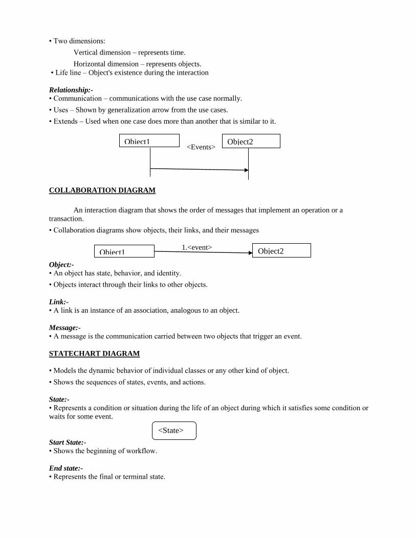
• Two dimensions:
Vertical dimension – represents time.
Horizontal dimension – represents objects.
• Life line – Object's existence during the interaction
Relationship:-
• Communication – communications with the use case normally.
• Uses – Shown by generalization arrow from the use cases.
• Extends – Used when one case does more than another that is similar to it.
<Events>
COLLABORATION DIAGRAM
An interaction diagram that shows the order of messages that implement an operation or a
transaction.
• Collaboration diagrams show objects, their links, and their messages
1.<event>
Object:-
• An object has state, behavior, and identity.
• Objects interact through their links to other objects.
Link:-
• A link is an instance of an association, analogous to an object.
Message:-
• A message is the communication carried between two objects that trigger an event.
STATECHART DIAGRAM
• Models the dynamic behavior of individual classes or any other kind of object.
• Shows the sequences of states, events, and actions.
State:-
• Represents a condition or situation during the life of an object during which it satisfies some condition or
waits for some event.
Start State:-
• Shows the beginning of workflow.
End state:-
• Represents the final or terminal state.
Object1 Object2
Object1 Object2
<State>
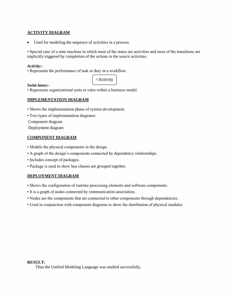
ACTIVITY DIAGRAM
Used for modeling the sequence of activities in a process.
• Special case of a state machine in which most of the states are activities and most of the transitions are
implicitly triggered by completion of the actions in the source activities.
Activity:-
• Represents the performance of task or duty in a workflow.
Swim lanes:-
• Represents organizational units or roles within a business model.
IMPLEMENTATION DIAGRAM
• Shows the implementation phase of system development.
• Two types of implementation diagrams:
Component diagram
Deployment diagram
COMPONENT DIAGRAM
• Models the physical components in the design.
• A graph of the design’s components connected by dependency relationships.
• Includes concept of packages.
• Package is used to show hoe classes are grouped together.
DEPLOYMENT DIAGRAM
• Shows the configuration of runtime processing elements and software components.
• It is a graph of nodes connected by communication association.
• Nodes are the components that are connected to other components through dependencies.
• Used in conjunction with component diagrams to show the distribution of physical modules
RESULT:
Thus the Unified Modeling Language was studied successfully.
<Activity
>
EX NO: 2 PASSPORT AUTOMATION SYSTEM
DATE:
AIM To develop the Passport Automation System using rational rose tools.
PROBLEM ANALYSIS AND PROJECT PLAN
To simplify the process of applying passport, software has been created by designing through
rational rose tool. Initially the applicant login the passport automation system and submits his details. These
details are stored in the database and verification process done by the passport administrator, regional
administrator and police the passport is issued to the applicant.
PROBLEM STATEMENT
• Passport Automation System (PAS) is used in the effective dispatch of passport to all of the applicants.
This system adopts a comprehensive approach to minimize the manual work and schedule resources, time
in a cogent manner.
• The core of the system is to get the online registration form (with details such as name, address etc.,) filled
by the applicant whose testament is verified for its genuineness by the Passport Automation System with
respect to the already existing information in the database.
• This forms the first and foremost step in the processing of passport application. After the first round of
verification done by the system, the information is in turn forwarded to the regional administrator's
(Ministry of External Affairs) office.
• The application is then processed manually based on the report given by the system, and any forfeiting
identified can make the applicant liable to penalty as per the law.
• The system forwards the necessary details to the police for its separate verification whose report is then
presented to the administrator. After all the necessary criteria have been met, the original information is
added to the database and the passport is sent to the applicant.
INTRODUCTION
Passport Automation System is an interface between the Applicant and the Authority responsible
for the Issue of Passport. It aims at improving the efficiency in the Issue of Passport and reduces the
complexities involved in it to the maximum possible extent.
PURPOSE
If the entire process of 'Issue of Passport' is done in a manual manner then it would take several
months for the passport to reach the applicant. Considering the fact that the number of applicants for
passport is increasing every year, an Automated System becomes essential to meet the demand. So this
system uses several programming and database techniques to elucidate the work involved in this process.
As this is a matter of National Security, the system has been carefully verified and validated in order to
satisfy it.
SCOPE
• The System provides an online interface to the user where they can fill in their personal details
• The authority concerned with the issue of passport can use this system to reduce his workload and process
the application in a speedy manner
• Provide a communication platform between the applicant and the administrator.
• Transfer of data between the Passport Issuing Authority and the Local Police for verification of applicant's
information.
USER CHARACTERISTICS
• Applicant - They are the people who desire to obtain the passport and submit the information to the
database.
• Administrator - He has the certain privileges to add the passport status and to approve the issue of
passport. He may contain a group of persons under him to verify the documents and give suggestion
whether or not to approve the dispatch of passport.
• Police - He is the person who upon receiving intimation from the PAS, perform a personal verification of
the applicant and see if he has any criminal case against him before or at present. He has been vetoed with
the power to decline an application by suggesting it to the Administrator if he finds any discrepancy with
the applicant. He communicates via this PAS.
CONSTRAINTS
• The applicants require a computer to submit their information.
• Although the security is given high importance, there is always a chance of intrusion in the web world
which requires constant monitoring.
• The user has to be careful while submitting the information. Much care is required.
ASSUMPTIONS AND DEPENDENCIES
• The Applicants and Administrator must have basic knowledge of computers and English Language.
• The applicants may be required to scan the documents and send.
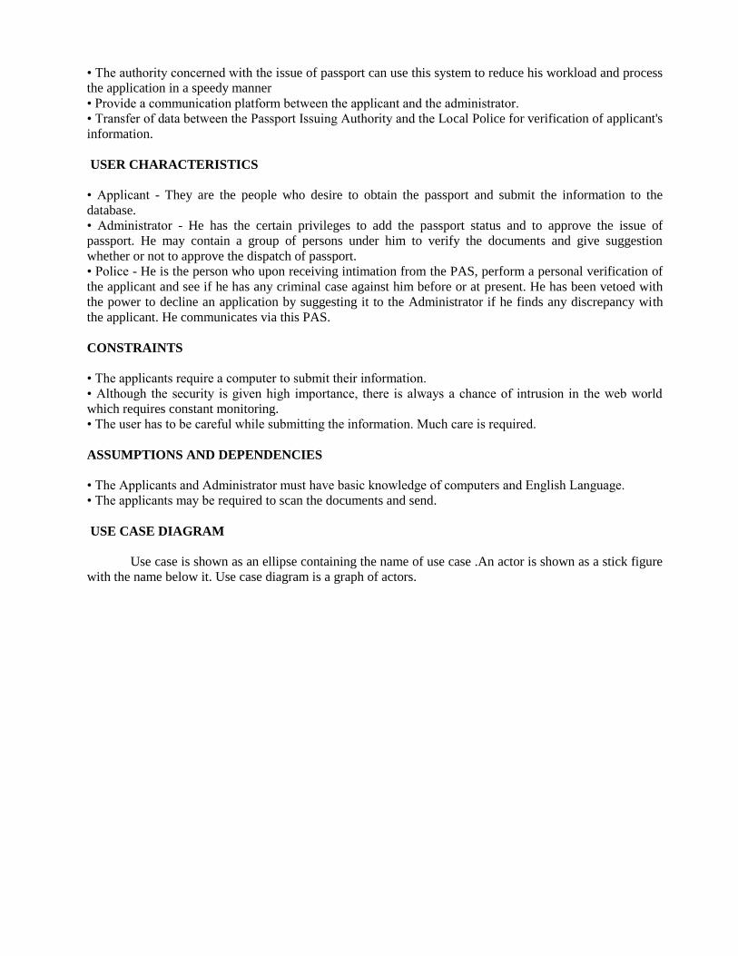
USE CASE DIAGRAM
Use case is shown as an ellipse containing the name of use case .An actor is shown as a stick figure
with the name below it. Use case diagram is a graph of actors.
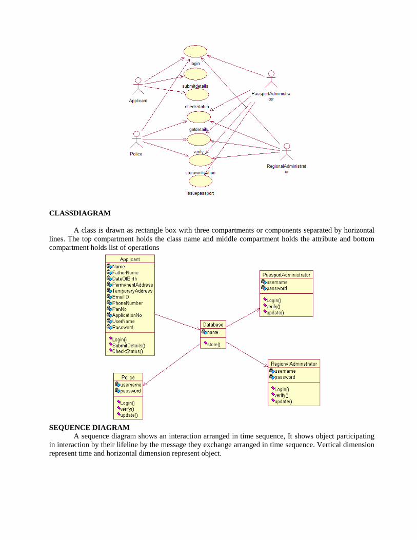
CLASSDIAGRAM
A class is drawn as rectangle box with three compartments or components separated by horizontal
lines. The top compartment holds the class name and middle compartment holds the attribute and bottom
compartment holds list of operations
SEQUENCE DIAGRAM
A sequence diagram shows an interaction arranged in time sequence, It shows object participating
in interaction by their lifeline by the message they exchange arranged in time sequence. Vertical dimension
represent time and horizontal dimension represent object.
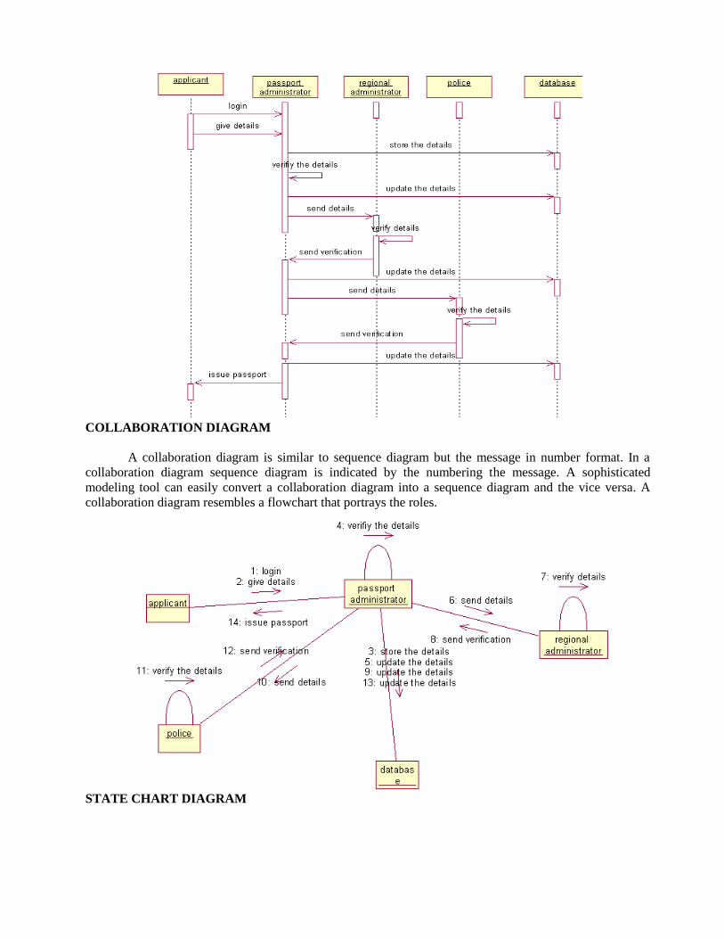
COLLABORATION DIAGRAM
A collaboration diagram is similar to sequence diagram but the message in number format. In a
collaboration diagram sequence diagram is indicated by the numbering the message. A sophisticated
modeling tool can easily convert a collaboration diagram into a sequence diagram and the vice versa. A
collaboration diagram resembles a flowchart that portrays the roles.
STATE CHART DIAGRAM
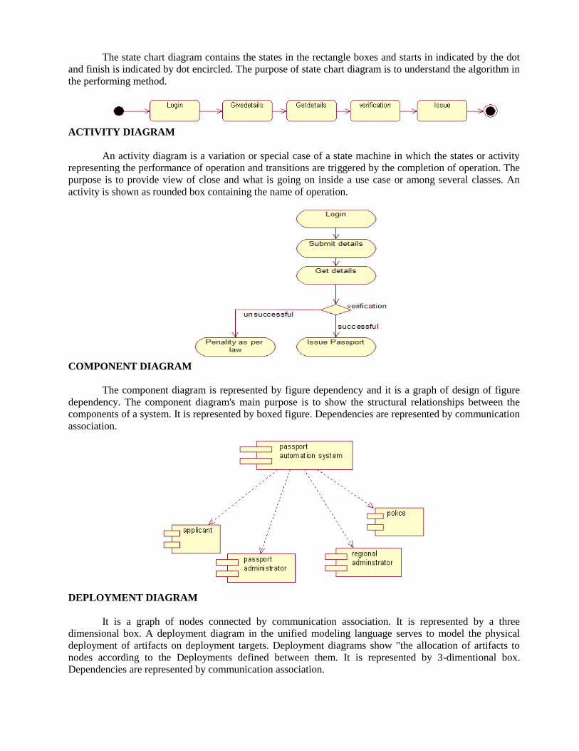
The state chart diagram contains the states in the rectangle boxes and starts in indicated by the dot
and finish is indicated by dot encircled. The purpose of state chart diagram is to understand the algorithm in
the performing method.
ACTIVITY DIAGRAM
An activity diagram is a variation or special case of a state machine in which the states or activity
representing the performance of operation and transitions are triggered by the completion of operation. The
purpose is to provide view of close and what is going on inside a use case or among several classes. An
activity is shown as rounded box containing the name of operation.
COMPONENT DIAGRAM
The component diagram is represented by figure dependency and it is a graph of design of figure
dependency. The component diagram's main purpose is to show the structural relationships between the
components of a system. It is represented by boxed figure. Dependencies are represented by communication
association.
DEPLOYMENT DIAGRAM
It is a graph of nodes connected by communication association. It is represented by a three
dimensional box. A deployment diagram in the unified modeling language serves to model the physical
deployment of artifacts on deployment targets. Deployment diagrams show "the allocation of artifacts to
nodes according to the Deployments defined between them. It is represented by 3-dimentional box.
Dependencies are represented by communication association.
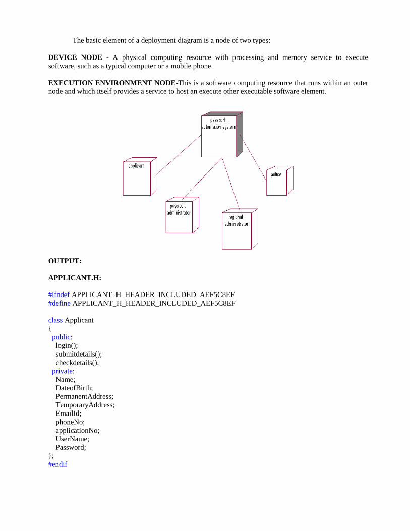
The basic element of a deployment diagram is a node of two types:
DEVICE NODE - A physical computing resource with processing and memory service to execute
software, such as a typical computer or a mobile phone.
EXECUTION ENVIRONMENT NODE-This is a software computing resource that runs within an outer
node and which itself provides a service to host an execute other executable software element.
OUTPUT:
APPLICANT.H:
#ifndef APPLICANT_H_HEADER_INCLUDED_AEF5C8EF
#define APPLICANT_H_HEADER_INCLUDED_AEF5C8EF
class Applicant
{
public:
login();
submitdetails();
checkdetails();
private:
Name;
DateofBirth;
PermanentAddress;
TemporaryAddress;
EmailId;
phoneNo;
applicationNo;
UserName;
Password;
};
#endif
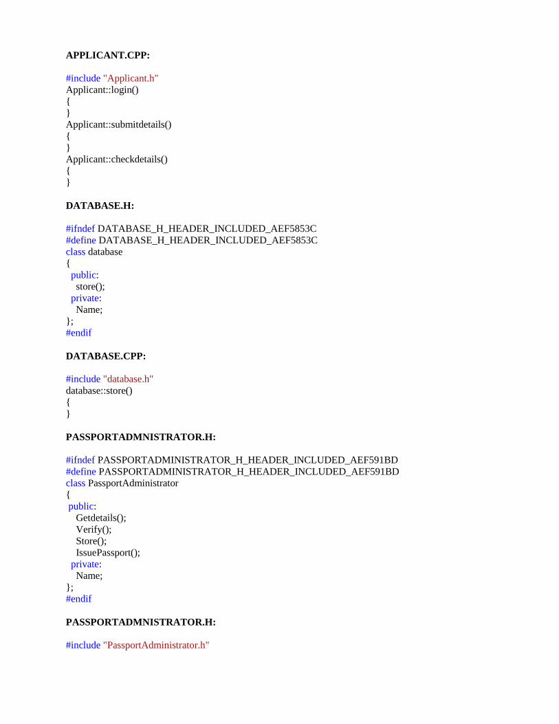
APPLICANT.CPP:
#include "Applicant.h"
Applicant::login()
{
}
Applicant::submitdetails()
{
}
Applicant::checkdetails()
{
}
DATABASE.H:
#ifndef DATABASE_H_HEADER_INCLUDED_AEF5853C
#define DATABASE_H_HEADER_INCLUDED_AEF5853C
class database
{
public:
store();
private:
Name;
};
#endif
DATABASE.CPP:
#include "database.h"
database::store()
{
}
PASSPORTADMNISTRATOR.H:
#ifndef PASSPORTADMINISTRATOR_H_HEADER_INCLUDED_AEF591BD
#define PASSPORTADMINISTRATOR_H_HEADER_INCLUDED_AEF591BD
class PassportAdministrator
{
public:
Getdetails();
Verify();
Store();
IssuePassport();
private:
Name;
};
#endif
PASSPORTADMNISTRATOR.H:
#include "PassportAdministrator.h"
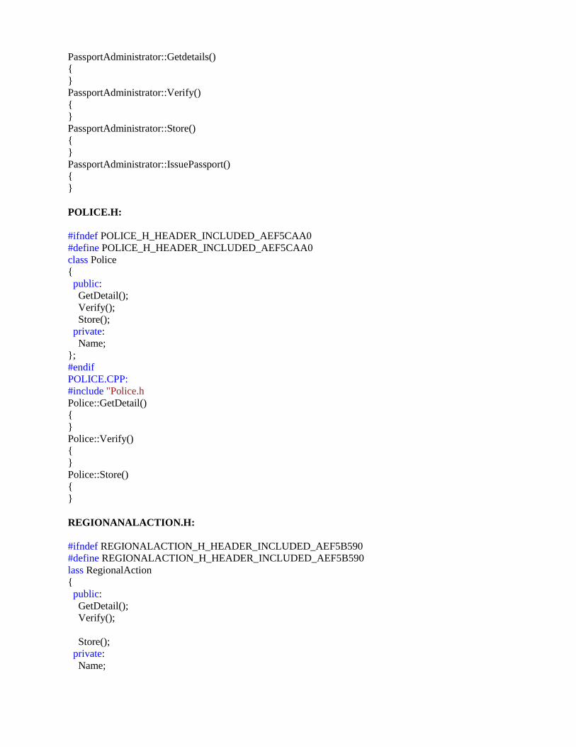
PassportAdministrator::Getdetails()
{
}
PassportAdministrator::Verify()
{
}
PassportAdministrator::Store()
{
}
PassportAdministrator::IssuePassport()
{
}
POLICE.H:
#ifndef POLICE_H_HEADER_INCLUDED_AEF5CAA0
#define POLICE_H_HEADER_INCLUDED_AEF5CAA0
class Police
{
public:
GetDetail();
Verify();
Store();
private:
Name;
};
#endif
POLICE.CPP:
#include "Police.h
Police::GetDetail()
{
}
Police::Verify()
{
}
Police::Store()
{
}
REGIONANALACTION.H:
#ifndef REGIONALACTION_H_HEADER_INCLUDED_AEF5B590
#define REGIONALACTION_H_HEADER_INCLUDED_AEF5B590
lass RegionalAction
{
public:
GetDetail();
Verify();
Store();
private:
Name;
};
#endif
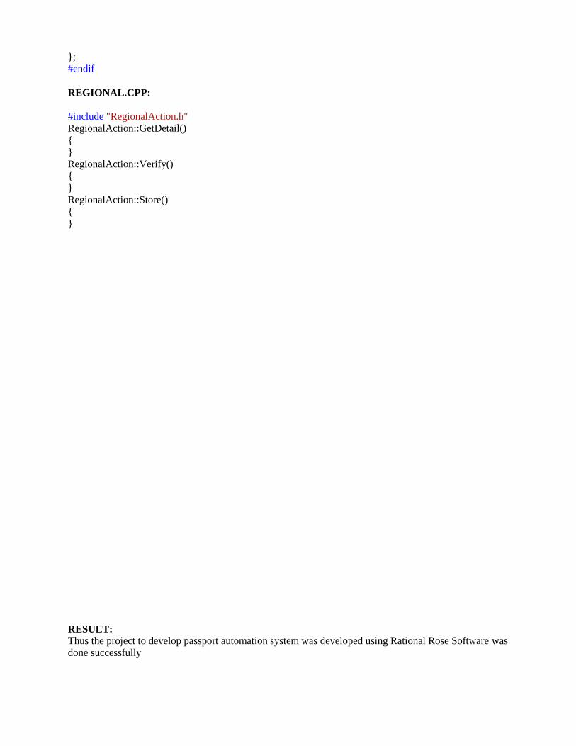
REGIONAL.CPP:
#include "RegionalAction.h"
RegionalAction::GetDetail()
{
}
RegionalAction::Verify()
{
}
RegionalAction::Store()
{
}
RESULT: Thus the project to develop passport automation system was developed using Rational Rose Software was
done successfully

EX NO: 3 BOOK BANK MANAGEMENT SYSTEM
DATE:
AIM To develop a project of Book bank management system using Rational Rose Software
PROBLEM ANALYSIS AND PROJECT DESIGN
The book bank management system is an software in which a member can register themselves and
then he can borrow books from the book bank. It mainly concentrates on providing books for engineering
students.
PROBLEM STATEMENT
The process of members registering and purchasing books from the book bank are described
sequentially through following steps:
• First the member registers himself if he was new to the book bank.
• Old members will directly select old member button..
• They select their corresponding year.
• After selecting the year they fill the necessary details and select the book and he will be directed towards
administrator
• The administrator will verify the status and issue the book.
INTRODUCTION
This system would be used by members who are students of any college to check the availability of
the books and borrow the books, and then the databases are updated. The purpose of this document is to
analyze and elaborate on the high-level needs and features of the book bank management system. It also
tells the usability, reliability defined in use case specification.
SCOPE
The scope of this book bank management system is to act as a tool for book bank administrator for
quick reference, availability of the books.
FUNCTIONALITY
Many members will be waiting to take the book from the book bank at a single day. To serve all the
members.
UML DIAGRAMS:
USE CASE DIAGRAM
A use case is a methodology used in system analysis to identify, clarify, and organize system
requirements. The use case is made up of a set of possible sequences of interactions between systems and
users in a particular environment and related to a particular goal. It is represented using ellipse. Actor is any
external entity that makes use of the system being modeled. It is represented using stick figure.

Book Bank
Register
Collecting the book
Student
Book details
issueing the book
Database
CLASS DIAGRAM
A class diagram in the unified modelling language (UML) is a type of static structure diagram that
describes the structure of a system by showing the system's classes, their attributes, and the relationships
between the classes. It is represented using a rectangle with three compartments. Top compartment have the
class name, middle compartments the attributes and the bottom compartment with operations.
SEQUENCE DIAGRAM
A sequence diagram in Unified Modeling Language (UML) is a kind of interaction diagram that
shows how processes operate with one another and in what order. It is a construct of a Message Sequence
Chart. There are two dimensions.
1. Vertical dimension-represent time.
2. Horizontal dimension-represent different objects.
StudentStudent Book BankBook Bank DatabaseDatabase
1: Register
2: check
3: submit book information
4: verify
5: issue the book
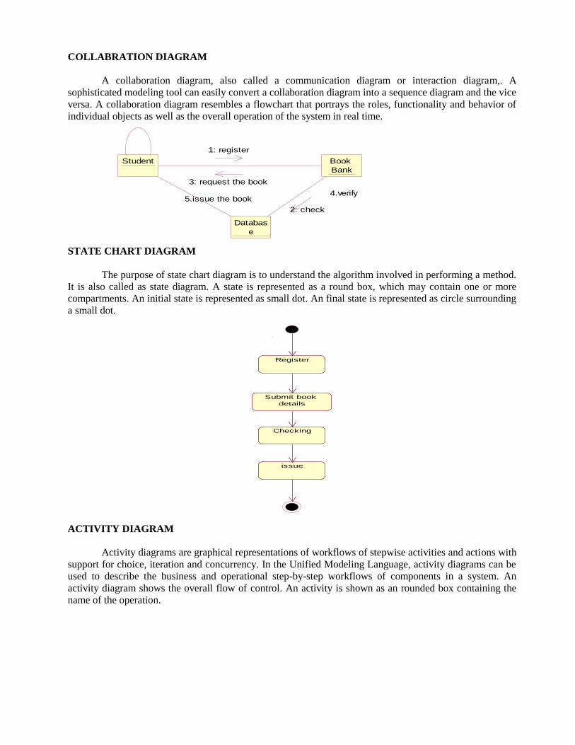
COLLABRATION DIAGRAM
A collaboration diagram, also called a communication diagram or interaction diagram,. A
sophisticated modeling tool can easily convert a collaboration diagram into a sequence diagram and the vice
versa. A collaboration diagram resembles a flowchart that portrays the roles, functionality and behavior of
individual objects as well as the overall operation of the system in real time.
Student Book
Bank
Databas
e
5.issue the book4.verify
1: register
3: request the book
2: check
STATE CHART DIAGRAM
The purpose of state chart diagram is to understand the algorithm involved in performing a method.
It is also called as state diagram. A state is represented as a round box, which may contain one or more
compartments. An initial state is represented as small dot. An final state is represented as circle surrounding
a small dot.
Register
Submit book
details
Checking
issue
ACTIVITY DIAGRAM
Activity diagrams are graphical representations of workflows of stepwise activities and actions with
support for choice, iteration and concurrency. In the Unified Modeling Language, activity diagrams can be
used to describe the business and operational step-by-step workflows of components in a system. An
activity diagram shows the overall flow of control. An activity is shown as an rounded box containing the
name of the operation.

Register
Submit
book detaill
Not
available
Get the
book
if
No
yes
COMPONENT DIAGRAM
The component diagram's main purpose is to show the structural relationships between the
components of a system. It is represented by boxed figure. Dependencies are represented by communication
association.
Book
Bank
Book details
issueing the bookCollecting the book
DEPLOYMENT DIAGRAM
A deployment diagram in the unified modeling language serves to model the physical deployment
of artifacts on deployment targets. Deployment diagrams show "the allocation of artifacts to nodes
according to the Deployments defined between them. It is represented by 3- dimentional box. Dependencies
are represented by communication association.
Collect
Databas
e
Book
details
issue
OUTPUT:
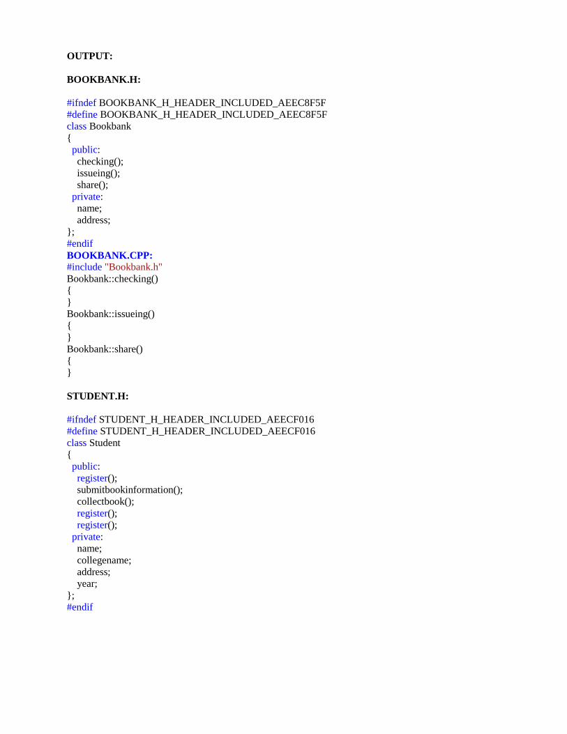
BOOKBANK.H:
#ifndef BOOKBANK_H_HEADER_INCLUDED_AEEC8F5F
#define BOOKBANK_H_HEADER_INCLUDED_AEEC8F5F
class Bookbank
{
public:
checking();
issueing();
share();
private:
name;
address;
};
#endif
BOOKBANK.CPP:
#include "Bookbank.h"
Bookbank::checking()
{
}
Bookbank::issueing()
{
}
Bookbank::share()
{
}
STUDENT.H:
#ifndef STUDENT_H_HEADER_INCLUDED_AEECF016
#define STUDENT_H_HEADER_INCLUDED_AEECF016
class Student
{
public:
register();
submitbookinformation();
collectbook();
register();
register();
private:
name;
collegename;
address;
year;
};
#endif

STUDENT.CPP:
#include "Student.h"
Student::register()
{
}
Student::submitbookinformation()
{
}
Student::collectbook()
{
}
Student::register()
{
}
RESULT Thus the project to develop book bank management system using Rational Rose Software was done
successfully.

EXNO: 4 EXAM REGISTRATION SYSTEM
DATE:
AIM To develop a project Exam Registration using Rational Rose Software.
PROBLEM ANALYSIS AND PROJECT PLANNING
The Exam Registration is an application in which applicant can register themselves for the exam.
The details of the students who have registered for the examination will be stored in a database and will be
maintained. The registered details can then be verified for any fraudulent or duplication and can be removed
if found so. The database which is verified can be used to issue hall tickets and other necessary materials to
the eligible students.
PROBLEM STATEMENT
The process of students accessing the registration application and applying for the examination by
filling out the form with proper details and then the authorities verify those details given for truth and
correctness are sequenced through steps
• The students access exam registration application.
• They fill out the form with correct and eligible details.
• They complete the payment process.
• The authorities verify or check the details.
• After all verification the exam registration database is finalized.
INTRODUCTION
Exam Registration application is an interface between the Student and the Authority responsible for
the Exams. It aims at improving the efficiency in the registration of exams and reduces the complexities
involved in it to the maximum possible extent.
SCOPE
The scope of this Exam Registration process is to provide an easy interface to the applicants where
they can fill their details and the authorities maintain those details in an easy and effective way.
FUNCTIONALITY
The main functionality of registration system is to make the registration and database for it to be
maintained in an efficient manner.
UML DIAGRAMS:
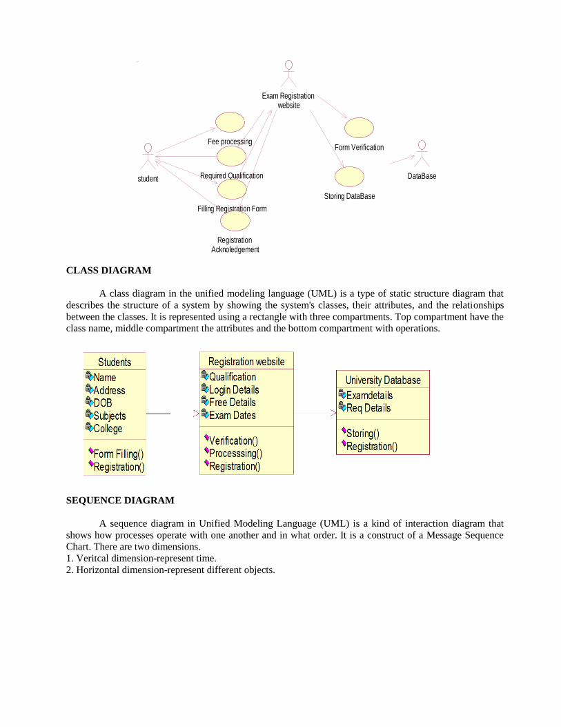
USE CASE DIAGRAM
A use case is a methodology used in system analysis to identify, clarify, and organize
system requirements. The use case is made up of a set of possible sequences of interactions
between systems and users in a particular environment and related to a particular goal. It is
represented using ellipse. Actor is any external entity that makes use of the system being modeled.
It is represented using stick figure.
Exam Registration website
Fee processing
student Required Qualification
Filling Registration Form
Registration Acknoledgement
Form Verification
DataBase
Storing DataBase
CLASS DIAGRAM
A class diagram in the unified modeling language (UML) is a type of static structure diagram that
describes the structure of a system by showing the system's classes, their attributes, and the relationships
between the classes. It is represented using a rectangle with three compartments. Top compartment have the
class name, middle compartment the attributes and the bottom compartment with operations.
SEQUENCE DIAGRAM
A sequence diagram in Unified Modeling Language (UML) is a kind of interaction diagram that
shows how processes operate with one another and in what order. It is a construct of a Message Sequence
Chart. There are two dimensions.
1. Veritcal dimension-represent time.
2. Horizontal dimension-represent different objects.
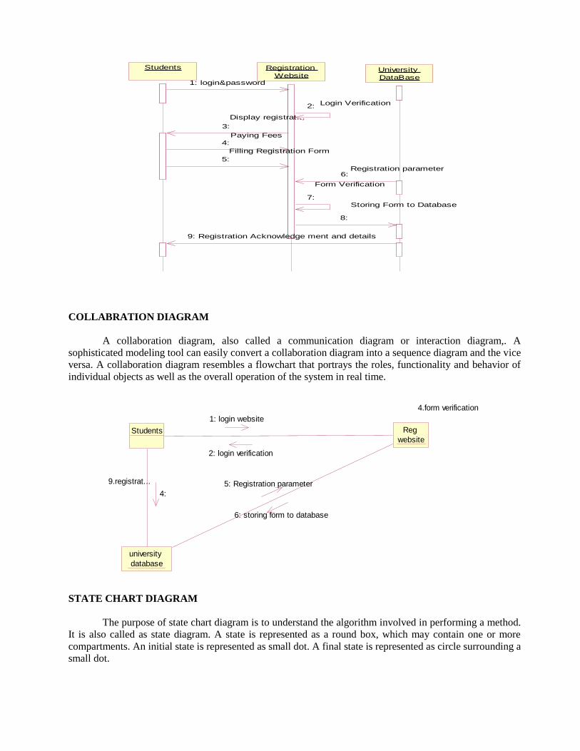
StudentsStudents Registration
Website
Registration
WebsiteUniversity
DataBase
University
DataBase1: login&password
2:
3:
4:
5:
6:
7:
8:
9: Registration Acknowledge ment and details
Login Verification
Display registrat...
Paying Fees
Filling Registration Form
Registration parameter
Form Verification
Storing Form to Database
COLLABRATION DIAGRAM
A collaboration diagram, also called a communication diagram or interaction diagram,. A
sophisticated modeling tool can easily convert a collaboration diagram into a sequence diagram and the vice
versa. A collaboration diagram resembles a flowchart that portrays the roles, functionality and behavior of
individual objects as well as the overall operation of the system in real time.
Students Reg
website
university
database
9.registrat...
4.form verification
4:
1: login website
2: login verification
5: Registration parameter
6: storing form to database
STATE CHART DIAGRAM
The purpose of state chart diagram is to understand the algorithm involved in performing a method.
It is also called as state diagram. A state is represented as a round box, which may contain one or more
compartments. An initial state is represented as small dot. A final state is represented as circle surrounding a
small dot.

Login Free payment&Processing
Filling Form
Form Verification
Storing to database
Registration Acknowledgement
ACTIVITY DIAGRAM
Activity diagrams are graphical representations of workflows of stepwise activities and actions with
support for choice, iteration and concurrency. In the Unified Modeling Language, activity diagrams can be
used to describe the business. An activity diagram shows the overall flow of control.
Login
website
Freepayment&
processing
Display
details& form
Form filling
form
verification
Storing to
database
Registration
acknowledgement
COMPONENT DIAGRAM
The component diagram's main purpose is to show the structural relationships between the
components of a system. It is represented by boxed figure. Dependencies are represented by communication
association.
Server
User
Interface
Data
Base
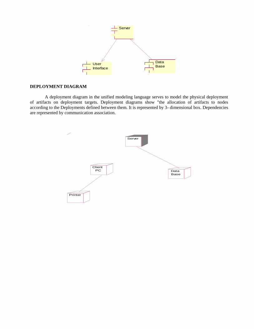
DEPLOYMENT DIAGRAM
A deployment diagram in the unified modeling language serves to model the physical deployment
of artifacts on deployment targets. Deployment diagrams show "the allocation of artifacts to nodes
according to the Deployments defined between them. It is represented by 3- dimensional box. Dependencies
are represented by communication association.
Server
Client
PC
Printer
Data
Base

OUTPUT:
REGWEBSITE.H:
#ifndef REG_WEBSITE_H_HEADER_INCLUDED_AEE3B2B5
#define REG_WEBSITE_H_HEADER_INCLUDED_AEE3B2B5
class Reg website
{
public:
verification();
processing();
registrating();
private:
Qualification;
login details;
fees details;
exam details;
};
#endif
REGWEBSITE.CPP:
#include "Reg website.h"
Reg website::verification()
{
}
Reg website::processing()
{
}
Reg website::registrating()
{
}
STUDENT1.H:
#ifndef STUDENT1_H_HEADER_INCLUDED_AEE3E628
#define STUDENT1_H_HEADER_INCLUDED_AEE3E628
class Student
{
public:
form filling();
registration();
private:
name;
address;
DOB;
subject;
collage;
};
#endif

STUDENT1.CPP:
#include "Student1.h"
Student::form filling()
{
}
Student::registration()
{
}
UNIVERSITY.H:
#ifndef UNIVERSITY_DATABASE_H_HEADER_INCLUDED_AEE3877C
#define UNIVERSITY_DATABASE_H_HEADER_INCLUDED_AEE3877C
class University Database
{
public:
storing registration();
private:
exam details;
reg details;
};
UNIVERSITY.CPP:
#include "University Database.h"
University Database::storing registration()
{
}
RESULT Thus the project to develop Exam Registration system using Rational Rose Software was done
successfully.
EX NO: 5 STOCK MAINTENANCE SYSTEM
DATE:
AIM To develop a project stock maintenance system using Rational Rose Software
PROBLEM ANALYSIS AND PROJECT PLANNING
The Stock Maintenance System, initial requirement to develop the project about the mechanism of
the Stock Maintenance System is caught from the customer. The requirement are analyzed and refined
which enables the end users to efficiently use Stock Maintenance System. The complete project is
developed after the whole project analysis explaining about the scope and the project statement is prepared.
PROBLEM STATEMENT
The process of stock maintenance system is that the customer login to the particular site to place the
order for the customer product. The stock maintenance system are described sequentially through steps
• The customer login to the particular site.
• They fill the customer details.
• They place the orders for their product.
• The vendor login and views the customer details and orders.
INTRODUCTION
This software specification documents full set of features and function for online stock maintenance
system that is performed in company website. In this we give specification about the customer orders. It
tells the usability, reliability defined in use case specification.
SCOPE
The scope of this stock maintenance system is to maintain the stock.
FUNCTIONALITY The main functionality of the stock maintenance system is to maintain the stock.
UML DIAGRAMS:
USE CASE DIAGRAM
A use case is a methodology used in system analysis to identify, clarify, and organize
system requirements. The use case is made up of a set of possible sequences of interactions
between systems and users in a particular environment and related to a particular goal. It is
represented using ellipse. Actor is any external entity that makes use of the system being modeled.
It is represented using stick figure.
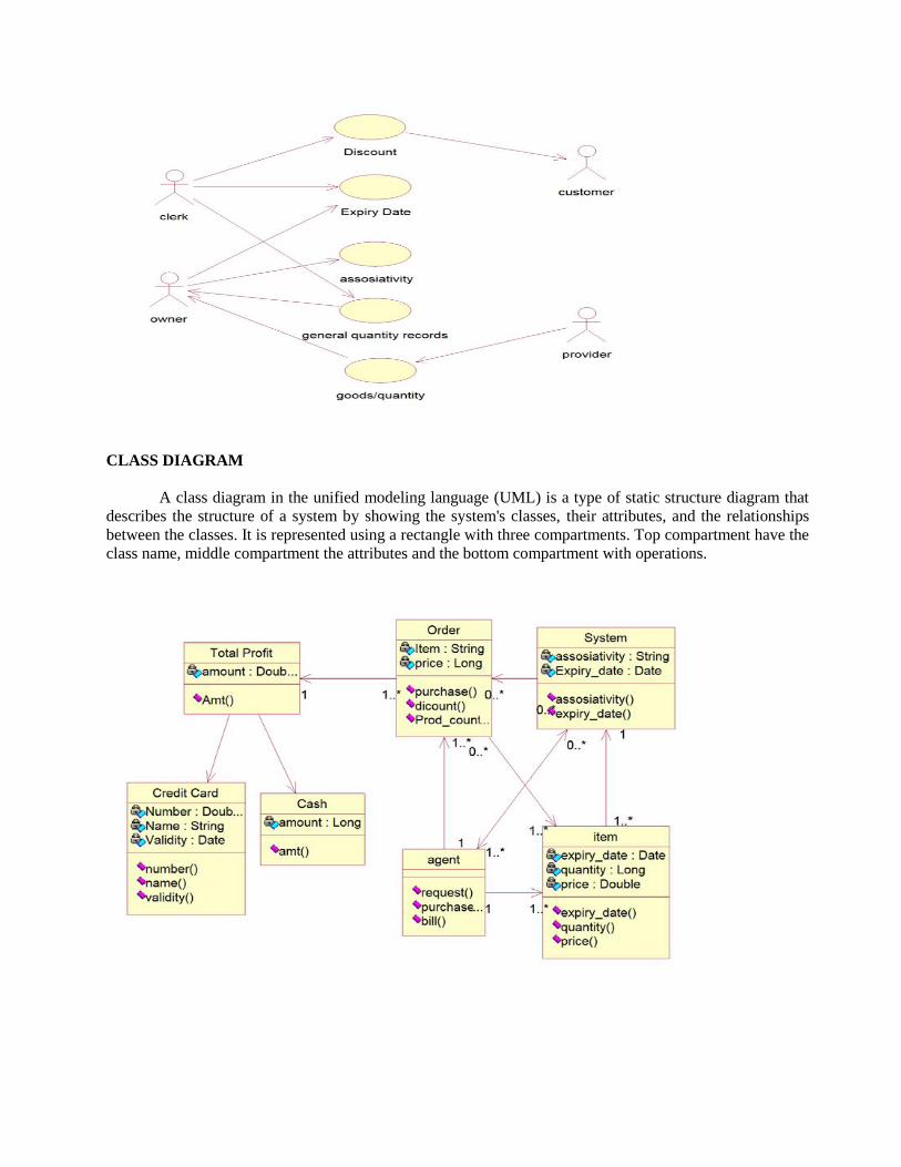
CLASS DIAGRAM
A class diagram in the unified modeling language (UML) is a type of static structure diagram that
describes the structure of a system by showing the system's classes, their attributes, and the relationships
between the classes. It is represented using a rectangle with three compartments. Top compartment have the
class name, middle compartment the attributes and the bottom compartment with operations.
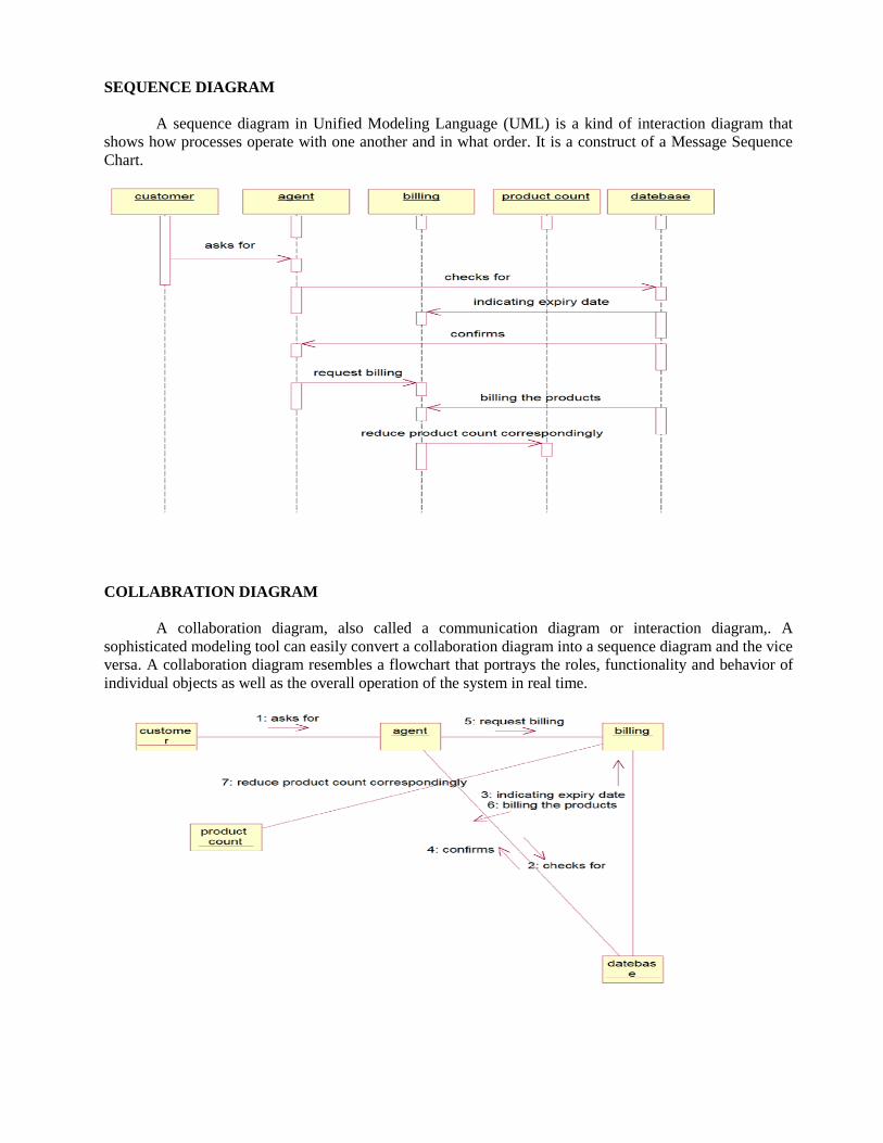
SEQUENCE DIAGRAM
A sequence diagram in Unified Modeling Language (UML) is a kind of interaction diagram that
shows how processes operate with one another and in what order. It is a construct of a Message Sequence
Chart.
COLLABRATION DIAGRAM
A collaboration diagram, also called a communication diagram or interaction diagram,. A
sophisticated modeling tool can easily convert a collaboration diagram into a sequence diagram and the vice
versa. A collaboration diagram resembles a flowchart that portrays the roles, functionality and behavior of
individual objects as well as the overall operation of the system in real time.
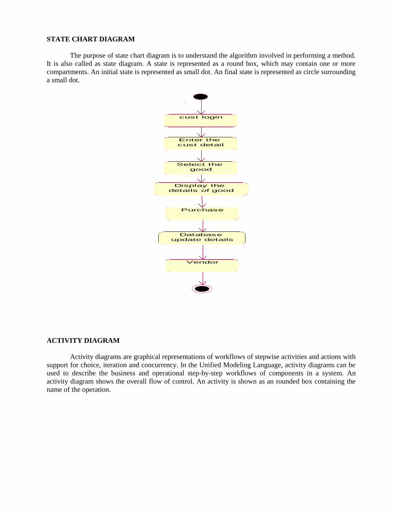
STATE CHART DIAGRAM
The purpose of state chart diagram is to understand the algorithm involved in performing a method.
It is also called as state diagram. A state is represented as a round box, which may contain one or more
compartments. An initial state is represented as small dot. An final state is represented as circle surrounding
a small dot.
cust login
Enter the
cust detail
Select the
good
Display the
details of good
Purchase
Database
update details
Vendor
ACTIVITY DIAGRAM
Activity diagrams are graphical representations of workflows of stepwise activities and actions with
support for choice, iteration and concurrency. In the Unified Modeling Language, activity diagrams can be
used to describe the business and operational step-by-step workflows of components in a system. An
activity diagram shows the overall flow of control. An activity is shown as an rounded box containing the
name of the operation.
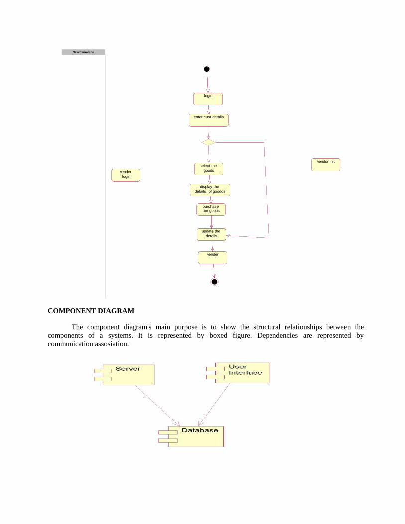
login
enter cust details
select the
goods
display the
details of goodds
purchase
the goods
update the
details
vender
vender
login
vendor init
NewSwimlane
COMPONENT DIAGRAM
The component diagram's main purpose is to show the structural relationships between the
components of a systems. It is represented by boxed figure. Dependencies are represented by
communication assosiation.
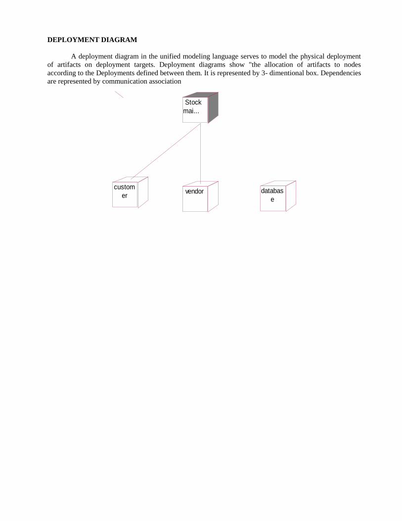
DEPLOYMENT DIAGRAM
A deployment diagram in the unified modeling language serves to model the physical deployment
of artifacts on deployment targets. Deployment diagrams show "the allocation of artifacts to nodes
according to the Deployments defined between them. It is represented by 3- dimentional box. Dependencies
are represented by communication association
Stock
mai...
custom
ervendor databas
e
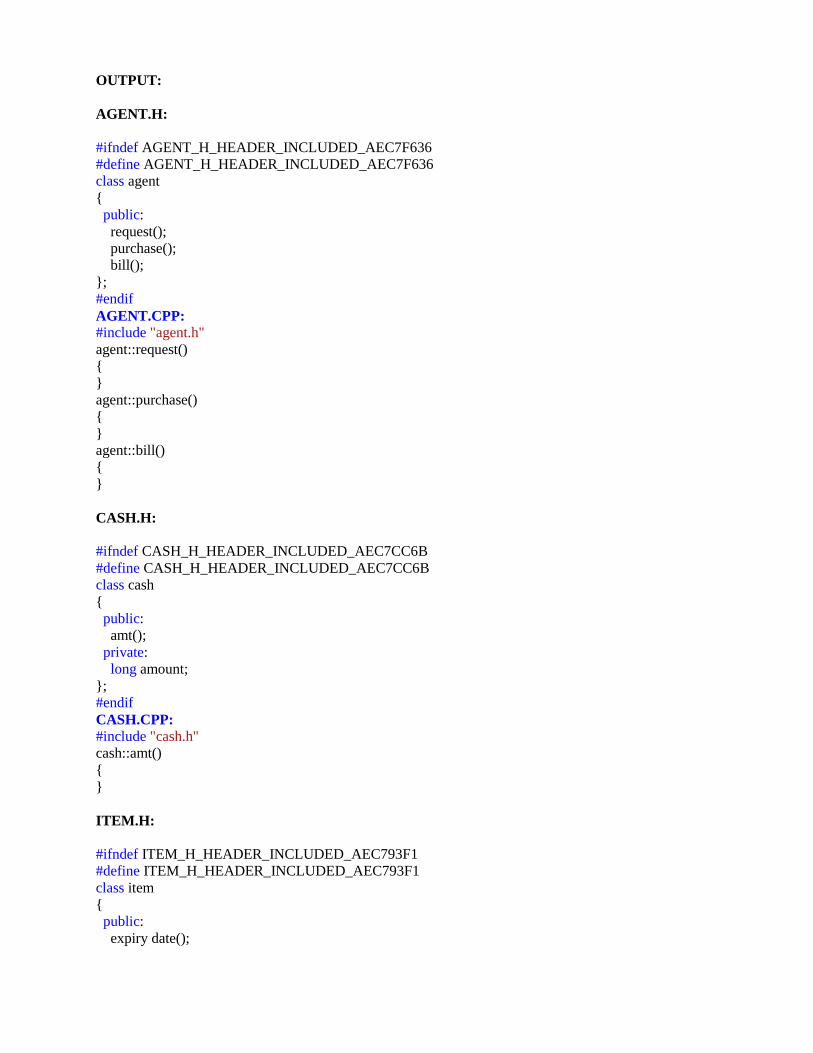
OUTPUT:
AGENT.H:
#ifndef AGENT_H_HEADER_INCLUDED_AEC7F636
#define AGENT_H_HEADER_INCLUDED_AEC7F636
class agent
{
public:
request();
purchase();
bill();
};
#endif
AGENT.CPP:
#include "agent.h"
agent::request()
{
}
agent::purchase()
{
}
agent::bill()
{
}
CASH.H:
#ifndef CASH_H_HEADER_INCLUDED_AEC7CC6B
#define CASH_H_HEADER_INCLUDED_AEC7CC6B
class cash
{
public:
amt();
private:
long amount;
};
#endif
CASH.CPP:
#include "cash.h"
cash::amt()
{
}
ITEM.H:
#ifndef ITEM_H_HEADER_INCLUDED_AEC793F1
#define ITEM_H_HEADER_INCLUDED_AEC793F1
class item
{
public:
expiry date();
Quantity();
price();
private:
Date expiry date;
Long quantity;
Double Price;
};
#endif
ITEM.CPP:
#include "item.h"
item::expiry date()
{
}
item::Quantity()
{
}
item::price()
{
}
ORDER.H:
#ifndef ORDER_H_HEADER_INCLUDED_AEC7FF8D
#define ORDER_H_HEADER_INCLUDED_AEC7FF8D
class order
{
public:
purchase();
discount(void 0);
product count();
private:
string Item;
Long price;
};
#endif
ORDER.CPP:
#include "order.h"
order::purchase()
{
}
order::discount(void 0)
{
}
order::product count()
{
}
SYSTEM.H
#ifndef SYSTEM_H_HEADER_INCLUDED_AEC7FA93
#define SYSTEM_H_HEADER_INCLUDED_AEC7FA93
class system
{
public:
associativity();
expiry date();
private:
String associativity;
Date expiry date;
};
#endif
SYSTEM.CPP:
#include "system.h"
system::associativity()
{
}
system::expiry date()
{
}
TOTAL PROFIT.H:
#ifndef TOATL_PROFIT_H_HEADER_INCLUDED_AEC79168
#define TOATL_PROFIT_H_HEADER_INCLUDED_AEC79168
class toatl profit
{
public:
amt();
private:
Date amount;
};
#endif
TOTAL PROFIT.CPP:
#include "toatl profit.h"
toatl profit::amt()
{
}
RESULT Thus the project to develop Stock Maintenance system using Rational Rose Software was done
successfully.
EX NO: 6 ONLINE COURSE RESERVATION SYSTEM
DATE:
AIM To design an object oriented model for course reservation system using Rational Rose Software.
PROBLEM ANALYSIS AND PROJECT PLANNING
The requirement form the customer is got and the requirements about the course registration are
defined. The requirements are analyzed and defined so that is enables the student to efficiency select a
course through registration system. The project scope is identified and the problem statement is prepared.
PROBLEM STATEMENT
• Whenever the student comes to join the course he/she should be provided with the list of course available
in the college.
• The system should maintain a list of professor who is teaching the course. At the end of the course the
student must be provided with the certificate for the completion of the course.
SCOPE
• In this specification, we define about the system requirements that are about from the functionality of the
system.
• It tells the users about the reliability defined in usecase specification
FUNCTIONALITY
Many members of the process line to check for its occurrences and transaction, we are have to carry
over at sometimes
UML DIAGRAMS:
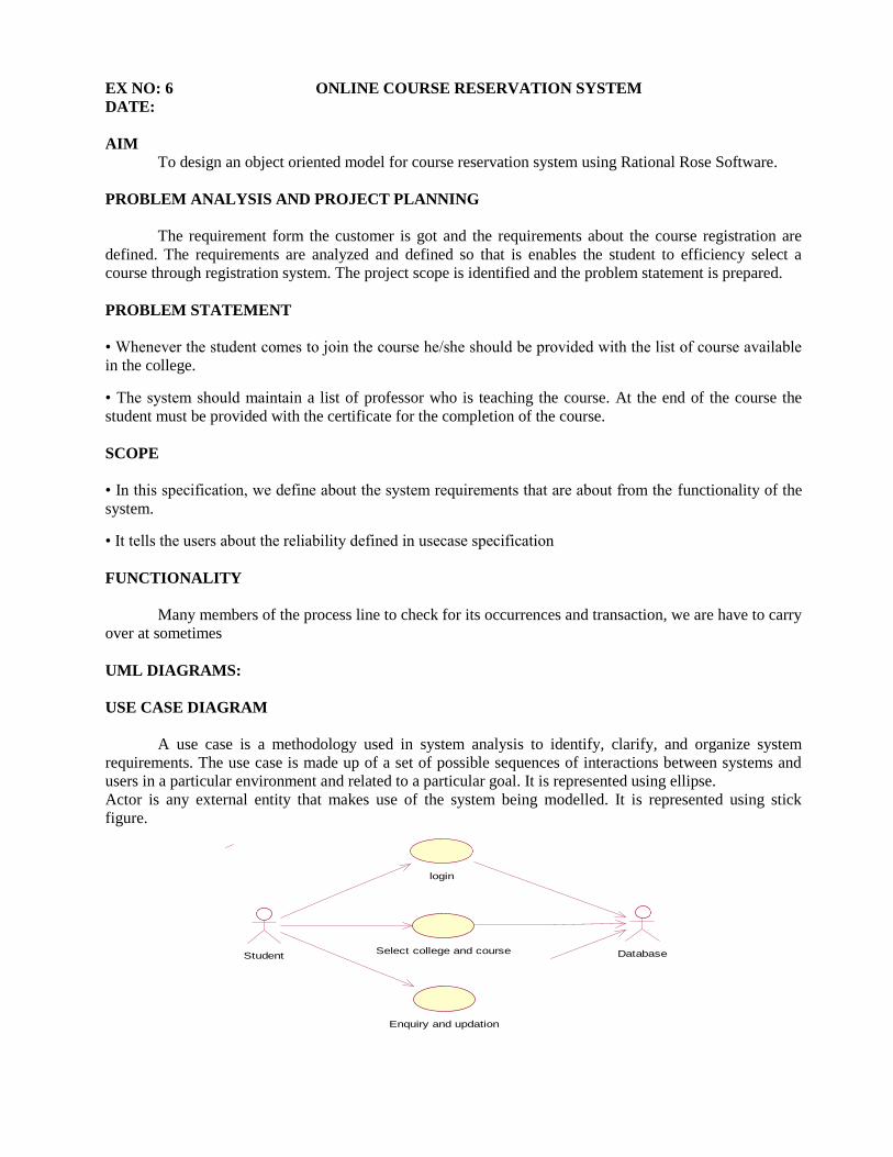
USE CASE DIAGRAM
A use case is a methodology used in system analysis to identify, clarify, and organize system
requirements. The use case is made up of a set of possible sequences of interactions between systems and
users in a particular environment and related to a particular goal. It is represented using ellipse.
Actor is any external entity that makes use of the system being modelled. It is represented using stick
figure.
Student
login
Select college and course Database
Enquiry and updation
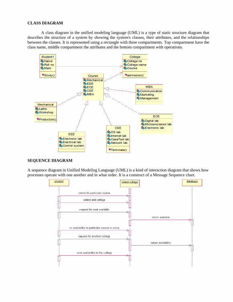
CLASS DIAGRAM
A class diagram in the unified modeling language (UML) is a type of static structure diagram that
describes the structure of a system by showing the system's classes, their attributes, and the relationships
between the classes. It is represented using a rectangle with three compartments. Top compartment have the
class name, middle compartment the attributes and the bottom compartment with operations.
SEQUENCE DIAGRAM
A sequence diagram in Unified Modeling Language (UML) is a kind of interaction diagram that shows how
processes operate with one another and in what order. It is a construct of a Message Sequence chart.

StudentStudent EnquiryEnquiry DatabaseDatabase
1: Request for information of the college
2: Provide details for the college
3: request for hostel facilities
4: check for availablity
5: Accept the hostel facilities
6: Join the college
7: Register the Student
COLLABORATION DIAGRAM
A collaboration diagram, also called a communication diagram or interaction diagram,. A
sophisticated modeling tool can easily convert a collaboration diagram into a sequence diagram and the vice
versa. A collaboration diagram resembles a flowchart that portrays the roles, functionality and behavior of
individual objects as well as the overall operation of the system in real time.

student
databas
e
enquiry
studentlogin
databas
e
student select
college
databas
e
1: request for the information
2: provide the details for the college
3: request for hostel college facilities
5: accept the hostel facilities
6: join in the college
4: check for availabilty
7: register the student
8: enter the username 9: enter the password 10: submit
11: verification
12: incorrect username or password login again
13: check for particular course
14: select the college
15: request seat availability
17: no availabilty to the particular course
18: request for another college
19: seat availabiltity to colleage
16: return availability
20: return available
STATE CHART DIAGRAM
The purpose of state chart diagram is to understand the algorithm involved in performing a method.
It is also called as state diagram. A state is represented as a round box, which may contain one or more
compartments. An initial state is represented as small dot. A final state is represented as circle surrounding a
small dot.
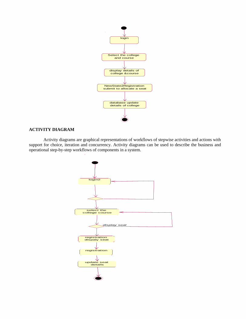
login
Select the college
and course
display details of
college &course
NewState2Registration
submit to allocate a seat
database update
details of college
ACTIVITY DIAGRAM
Activity diagrams are graphical representations of workflows of stepwise activities and actions with
support for choice, iteration and concurrency. Activity diagrams can be used to describe the business and
operational step-by-step workflows of components in a system.
login2
select the
college course
display seat
registration
dispaly seat
registration
update seat
details
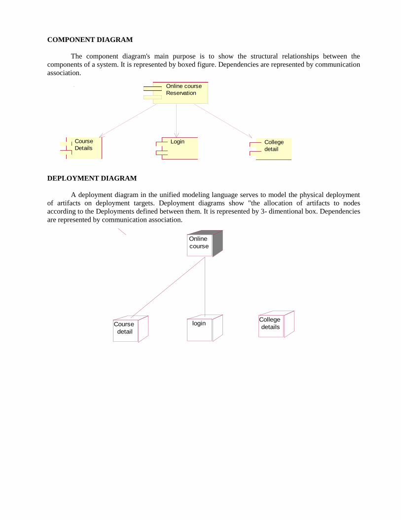
COMPONENT DIAGRAM
The component diagram's main purpose is to show the structural relationships between the
components of a system. It is represented by boxed figure. Dependencies are represented by communication
association.
Online course
Reservation
Course
DetailsLogin College
detail
DEPLOYMENT DIAGRAM
A deployment diagram in the unified modeling language serves to model the physical deployment
of artifacts on deployment targets. Deployment diagrams show "the allocation of artifacts to nodes
according to the Deployments defined between them. It is represented by 3- dimentional box. Dependencies
are represented by communication association.
login
Online
course
Course
detail
College
details
OUTPUT:
IT.H:
#ifndef CSE_IT_H_HEADER_INCLUDED_AEC7DB13
#define CSE_IT_H_HEADER_INCLUDED_AEC7DB13
class CSE/IT : public Course
{
public:
#include "Course.h"
terminate();
private:
os alb;
internal lab;
casetool lab;
network lab;
};
#endif
IT.CPP:
#include “CSE/IT.h”
CSE/IT :: Terminate()
{
}
COLLAGE.H:
#ifndef COLLAGE_H_HEADER_INCLUDED_AEC7CAE0
#define COLLAGE_H_HEADER_INCLUDED_AEC7CAE0
class Collage
{
public:
admision();
private:
college no;
college name;
course;
};
#endif
COLLAGE.CPP:
#include "College.h"
Collage::admision()
{
}
ECE.H:
#ifndef ECE_H_HEADER_INCLUDED_AEC7B20F
#define ECE_H_HEADER_INCLUDED_AEC7B20F
#include "Course.h"
class ECE : public Course
{
digital lab;
microprocessor lab;
electronic lab;
};
#endif
ECE.CPP:
#include "ECE.h"
EEE.H:
#ifndef EEE_H_HEADER_INCLUDED_AEC7C8FC
#define EEE_H_HEADER_INCLUDED_AEC7C8FC
#include "Course.h"
class EEE : public Course
{
Electronic lab;
Electricacl lab;
Control system;
};
#endif
EEE.CPP:
#include “EEE.h”
MBA.H:
#ifndef MBA_H_HEADER_INCLUDED_AEC7F486
#define MBA_H_HEADER_INCLUDED_AEC7F486
#include "Course.h"
class MBA : public Course
{
communicaton;
marketing;
management;
};
#endif
MBA.CPP:
#include "MBA.h"
MECHANICAL.H:
#ifndef MECHANICAL_H_HEADER_INCLUDED_AEC7DFFF
#define MECHANICAL_H_HEADER_INCLUDED_AEC7DFFF
#include "Course.h"
class Mechanical : public Course
{

public:
production();
private:
lathe;
workshop;
};
#endif
MECHANICAL.CPP:
#include "Mechanical.h"
Mechanical::production()
{
}
STUDENT.H:
#ifndef STUDENT_H_HEADER_INCLUDED_AEC7F76B
#define STUDENT_H_HEADER_INCLUDED_AEC7F76B
class Student
{
public:
study();
private:
name;
roll no;
mark;
};
#endif
STUDENT.CPP:
#include "Student.h"
Student::study()
{
}
RESULT Thus the project to develop online course reservation system was developed using Rational Rose Software
was done successfully.
EXNO: 7 E-TICKETING
DATE:
AIM To develop the E-Ticketing System using Rational Rose Software.
PROBLEM ANALYSIS AND PROJECT PLANNING
In the E-Ticketing system the main process is a applicant have to login the database then the
database verifies that particular username and password then the user must fill the details about their
personal details then selecting the flight and the database books the ticket then send it to the applicant then
searching the flight or else cancelling the process.
PROBLEM STATEMENT
The E-Ticketing system is the initial requirement to develop the project about the mechanism of the
E-ticketing system what the process do at all.
• The requirement are analyzed and refined which enables the end users to efficiently use the E-ticketing
system.
• The complete project is developed after the whole project analysis explaining about scope and project
statement is prepared.
• The main scope for this project is the applicant should reserved for the flight ticket.
• First the applicant wants to login to the database after that the person wants to fill their details.
• Then the database will seach for ticket or else the person will cancelled the ticket if he/she no need.
FUNCTIONALITY
The database should be act as an main role of the e-ticketing system it can be booking the ticket in
easy way.
.
UML DIAGRAMS:
USE CASE DIAGRAM
A use case is a methodology used in system analysis to identify, clarify, and organize system
requirements. The use case is made up of a set of possible sequences of interactions between systems and
users in a particular environment and related to a particular goal. It is represented using ellipse.
Actor is any external entity that makes use of the system being modeled. It is represented using stick figure.

applicant
login
filling details
book ticket
selecting flight
search
E-ticketing database
cancel ticket
CLASS DIAGRAM
A class diagram in the unified modeling language (UML) is a type of static structure diagram that
describes the structure of a system by showing the system's classes, their attributes, and the relationships
between the classes. It is represented using a rectangle with three compartments. Top compartment have the
classname, middle compartment the attributes and the bottom compartment with operations.
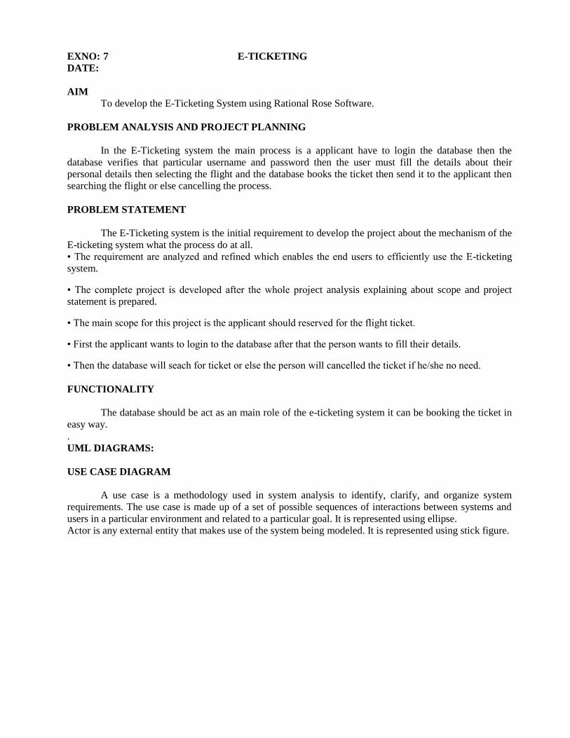
SEQUENCE DIAGRAM
A sequence diagram in Unified Modeling Language (UML) is a kind of interaction diagram that
shows how processes operate with one another and in what order. It is a construct of a Message Sequence
Chart. There are two dimensions.
1. Vertical dimension-represent time.
2. Horizontal dimension-represent different objects.
COLLABRATION DIAGRAM
A collaboration diagram, also called a communication diagram or interaction diagram,. A
sophisticated modeling tool can easily convert a collaboration diagram into a sequence diagram and the vice
versa. A collaboration diagram resembles a flowchart that portrays the roles, functionality and behavior of
individual objects as well as the overall operation of the system in real time.
applicant airline
database
2: login verification
1: login
3: display form
4: filling form
5: selecting flight6: booking ticket7: cancelling ticket8: verifing ticket
9: display ticket information
10: issue ticket acknowledgment
apllicantapllicant airline databaseairline database
1: login
2: display form
3: filling form
4: slecting flight
5: booking ticket
6: cancelling ticket
7: verifying ticket
8: display ticket information
9: issue ticket acknowledgment
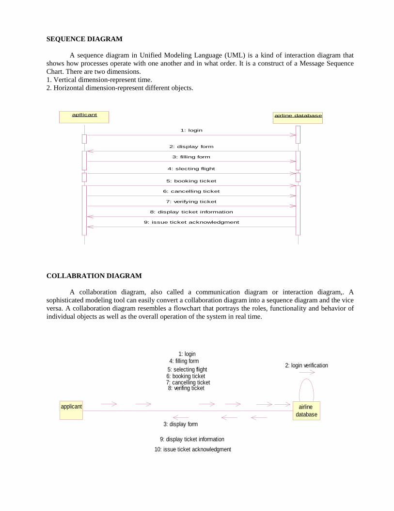
STATE CHART DIAGRAM
The purpose of state chart diagram is to understand the algorithm involved in performing a method.
It is also called as state diagram. A state is represented as a round box, which may contain one or more
compartments. An initial state is represented as small dot. A final state is represented as circle surrounding a
small dot.
login filling
detailsselecting
flight
book ticket search cancel
ACTIVITY DIAGRAM
Activity diagrams are graphical representations of workflows of stepwise activities and actions with
support for choice, iteration and concurrency. In the Unified Modeling Language, activity diagrams can be
used to describe the business and operational step-by-step workflows of components in a system. An
activity diagram shows the overall flow of control. An activity is shown as an rounded box containing the
name of the operation.
login
fill details
select flight
book ticket
seach
ticket
cancelling
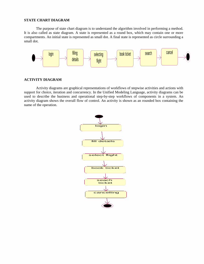
COMPONENT DIAGRAM
The component diagram's main purpose is to show the structural relationships between the
components of a system. It is represented by boxed figure. Dependencies are represented by communication
association.
E-Tick
eting
login filling
details
selecting
flight
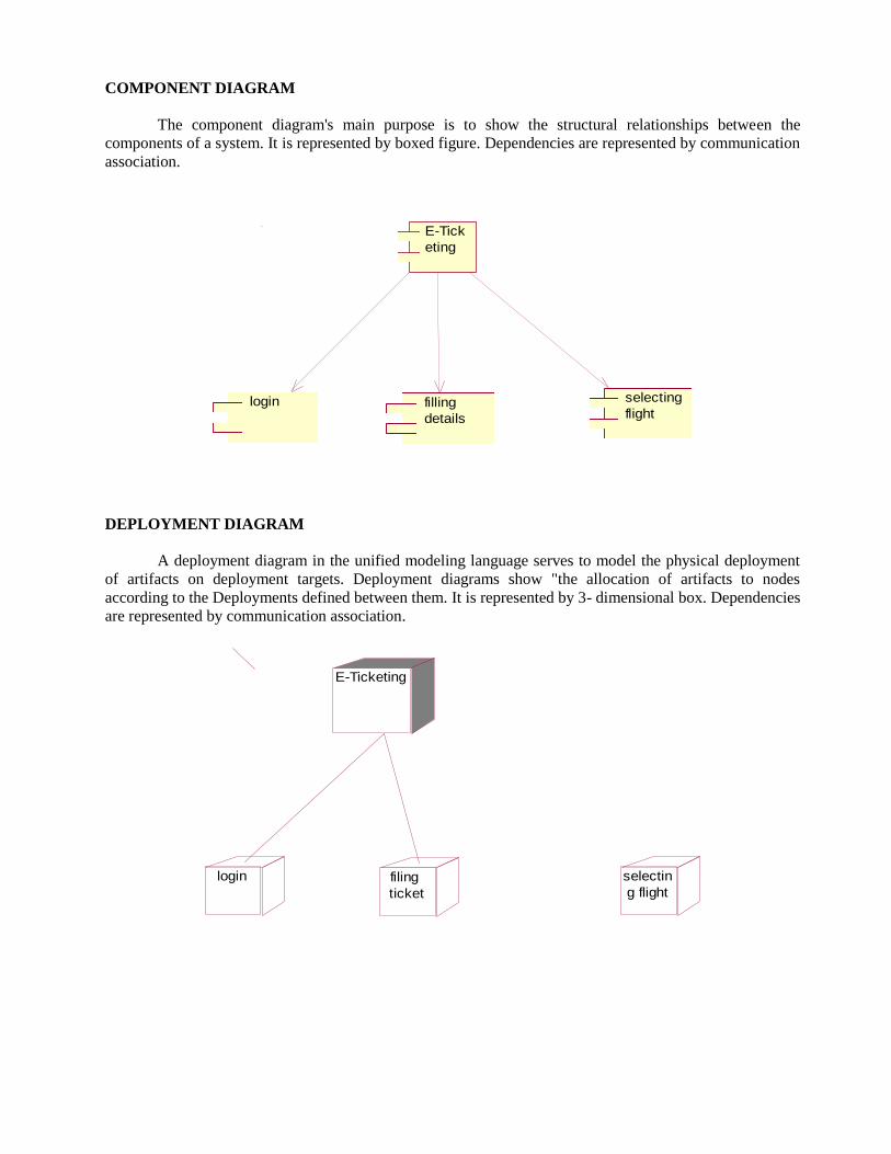
DEPLOYMENT DIAGRAM
A deployment diagram in the unified modeling language serves to model the physical deployment
of artifacts on deployment targets. Deployment diagrams show "the allocation of artifacts to nodes
according to the Deployments defined between them. It is represented by 3- dimensional box. Dependencies
are represented by communication association.
E-Ticketing
login filing
ticket
selectin
g flight

OUTPUT:
APPLICANT.H:
#ifndef APPLICANT_H_HEADER_INCLUDED_AEBEF109
#define APPLICANT_H_HEADER_INCLUDED_AEBEF109
class Applicant
{
public:
filling details();
selecting flight();
book ticket();
cancel ticket();
private:
passsport code;
first name;
last name;
adderss;
nationality;
phone;
sex;
passport number;
resident perm it;
book date;
destination;
departure date;
flight name;
flight no;
amount;
};
#endif
APPLICANT.CPP:
#include "Applicant.h"
Applicant::filling details()
{
}
Applicant::selecting flight()
{
}
Applicant::book ticket()
{
}
Applicant::cancel ticket()
{}
ETICKETING DATABASE.H:
#ifndef ETICKETING_DATABASE_H_HEADER_INCLUDED_AEBE91A7
#define ETICKETING_DATABASE_H_HEADER_INCLUDED_AEBE91A7
class Eticketing database
{
public:
ticket booking();
hotel booking();
verifing ticket();
private:
airlines;
hotel res;
};
#endif
ETICKETING DATABASE.CPP:
#include "Eticketing database.h"
Eticketing database::ticket booking()
{
}
Eticketing database::hotel booking()
{
}
Eticketing database::verifing ticket()
{
}
RESULT Thus the project to develop E-Ticketing system using Rational Rose Software was done
successfully.
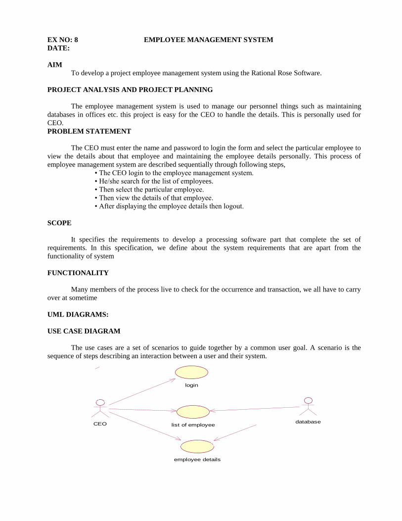
EX NO: 8 EMPLOYEE MANAGEMENT SYSTEM
DATE:
AIM To develop a project employee management system using the Rational Rose Software.
PROJECT ANALYSIS AND PROJECT PLANNING
The employee management system is used to manage our personnel things such as maintaining
databases in offices etc. this project is easy for the CEO to handle the details. This is personally used for
CEO.
PROBLEM STATEMENT
The CEO must enter the name and password to login the form and select the particular employee to
view the details about that employee and maintaining the employee details personally. This process of
employee management system are described sequentially through following steps,
• The CEO login to the employee management system.
• He/she search for the list of employees.
• Then select the particular employee.
• Then view the details of that employee.
• After displaying the employee details then logout.
SCOPE
It specifies the requirements to develop a processing software part that complete the set of
requirements. In this specification, we define about the system requirements that are apart from the
functionality of system
FUNCTIONALITY
Many members of the process live to check for the occurrence and transaction, we all have to carry
over at sometime
UML DIAGRAMS:
USE CASE DIAGRAM
The use cases are a set of scenarios to guide together by a common user goal. A scenario is the
sequence of steps describing an interaction between a user and their system.
login
list of employeeCEO
employee details
database

CLASS DIAGRAM
The Class diagram the types of object in the system a various kinds of static relation ships that
exists among them
STATE CHART DIAGRAM:
It is a technique to describe the behavior of the system.It determines all the possible states as that of
particular object gets into the object oriented technique.State diagrams are drawn for a single class so status
to the lifetime behavior of a single objector.
login
select the list
of employee
diplay the list
of employee
select employee
details
updated
the details
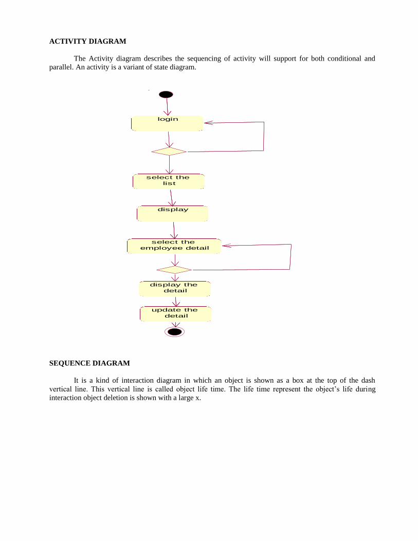
ACTIVITY DIAGRAM
The Activity diagram describes the sequencing of activity will support for both conditional and
parallel. An activity is a variant of state diagram.
login
select the
list
display
select the
employee detail
display the
detail
update the
detail
SEQUENCE DIAGRAM
It is a kind of interaction diagram in which an object is shown as a box at the top of the dash
vertical line. This vertical line is called object life time. The life time represent the object’s life during
interaction object deletion is shown with a large x.

ceoceo
ceoceo
empolyee detailempolyee detail
loginlogin
databasedatabase
databasedatabase
1: enter the username
2: enter the password
3: check the availability
4: incorrect username and password
5: login again
6: request for information of list employee
7: search the list
8: check the availabilty
9: provide details
10: check for particular employee detail
11: check for availability
12: return if available
13: send the details
COLLABORATION DIAGRAM
In a collaboration diagram object are shown as icons as on. A collaboration diagram arrow indicates
the message send within the given use case. The sequence is indicated by numbering the messages.
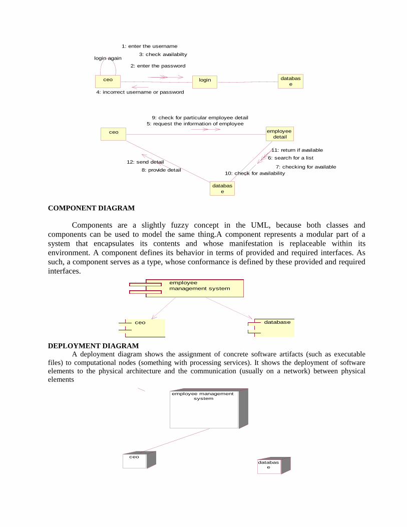
ceo login databas
e
login again
ceo employee
detail
databas
e
1: enter the username
2: enter the password
3: check availabilty
4: incorrect username or password
5: request the information of employee
9: check for particular employee detail
8: provide detail
12: send detail6: search for a list
7: checking for available
10: check for availability
11: return if available
COMPONENT DIAGRAM
Components are a slightly fuzzy concept in the UML, because both classes and
components can be used to model the same thing.A component represents a modular part of a
system that encapsulates its contents and whose manifestation is replaceable within its
environment. A component defines its behavior in terms of provided and required interfaces. As
such, a component serves as a type, whose conformance is defined by these provided and required
interfaces.
employee
management system
ceo database
DEPLOYMENT DIAGRAM
A deployment diagram shows the assignment of concrete software artifacts (such as executable
files) to computational nodes (something with processing services). It shows the deployment of software
elements to the physical architecture and the communication (usually on a network) between physical
elements
employee management
system
ceo
databas
e

OUTPUT:
CEO.H:
#ifndef CEO_H_HEADER_INCLUDED_AEA287B1
#define CEO_H_HEADER_INCLUDED_AEA287B1
class CEO
{
public:
view();
update();
login();
private:
name;
Empno;
DOB;
};
#endif
CEO.CPP:
#include "CEO.h"
CEO::view()
{
}
CEO::update()
{
}
CEO::login()
{
}
DATABASE.H:
#ifndef DATABASE_H_HEADER_INCLUDED_AEA2B9D5
#define DATABASE_H_HEADER_INCLUDED_AEA2B9D5
#include "employee.h"
class database : public employee
{
public:
storedata();
update();
insert();
enquiry();
delete();
verify();
display();
private:
products;
projects;
};
#endif

DATABASE.CPP:
#include "database.h"
database::storedata()
{
}
database::update()
{
}
database::insert()
{
}
database::enquiry()
{
}
database::delete()
{
}
database::verify()
{
}
database::display()
{
}
EMPLOYEE.H:
#ifndef EMPLOYEE_H_HEADER_INCLUDED_AEA2DB06
#define EMPLOYEE_H_HEADER_INCLUDED_AEA2DB06
class employee
{
name;
DOB;
salary;
exp;
phno;
};
#endif
EMPLOYEE.CPP:
#include "employee.h"
RESULT
Thus the project is to develop an EMPLOYEE MANAGEMENT SYSTEM using the Rational Rose
Software was done successfully.
EX NO: 9 CREDIT CARD PROCESSING SYSTEM
DATE:
AIM To develop a project credit card system using the Rational Rose Software.
PROBLEM ANALYSIS AND PROJECT PLANNING
The Credit Card Processing System which is use to purchasing an item from any shop mall, and it is
used to maintain the limitation of credit card balance and current transaction process could be update via
credit card machine. This project mainly used for large amount of item can be easy to buy from anywhere
and required transaction process should be maintained them.
PROBLEM STATEMENT
The customer should select the item to be purchase from the shop by using credit card payment then
the vendor should give a bill for the selected item .The customer should give his card to swap and request
for the kind of amount transaction. After processing the transaction, the CREDIT CARD MACHINE should
give the balance print statement or receipt.
• Customer should select the item from the shop.
• Vendor makes the bill for the selected item.
• Customer gives the credit card to the vendor to swap the card.
• They required amount transaction is done by the card reader.
• Vendor will issue the balance statement to the customer.
• Customers put the signature in the receipt and return to the vendor
FUNCTIONALITY
Many members of the process lives to checking for the occurrence and transaction we all have to
carry over sometimes user interface to make the transaction to be efficient.
ASSUMPTION AND DEPENDENCIES
The Vendor and Customer must have basic knowledge of computers and English Language. The
vendor may be required to delivered the item purchased by the customer.
UML DIAGRAMS
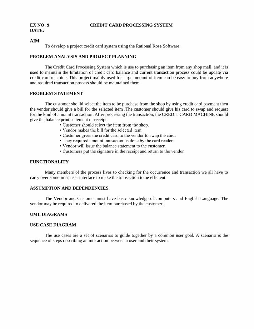
USE CASE DIAGRAM
The use cases are a set of scenarios to guide together by a common user goal. A scenario is the
sequence of steps describing an interaction between a user and their system.

purchase item
swap the card
customer
bill the issue
siganture
vendor
deleiver the item
print statement
card reader
make transaction
CLASS DIAGRAM
The Class diagram the types of object in the system an the various kinds of static relation ships that
exists among them.
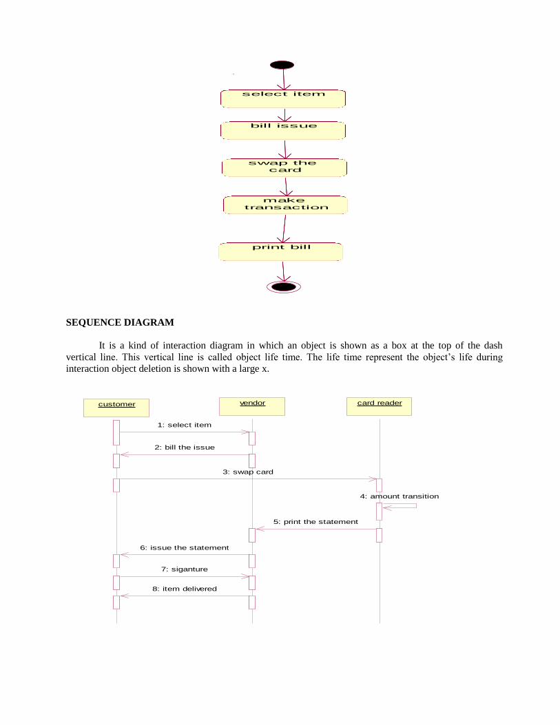
STATECHART DIAGRAM
It is a familiar technique to describe the behavior of the system. Events involve in the state chart
diagram a purchase, make transaction, delivery the item.
select item
bill issue
swap the
card
make
transaction
print bill
SEQUENCE DIAGRAM
It is a kind of interaction diagram in which an object is shown as a box at the top of the dash
vertical line. This vertical line is called object life time. The life time represent the object’s life during
interaction object deletion is shown with a large x.
customercustomer vendorvendor card readercard reader
1: select item
2: bill the issue
3: swap card
4: amount transition
5: print the statement
6: issue the statement
7: siganture
8: item delivered
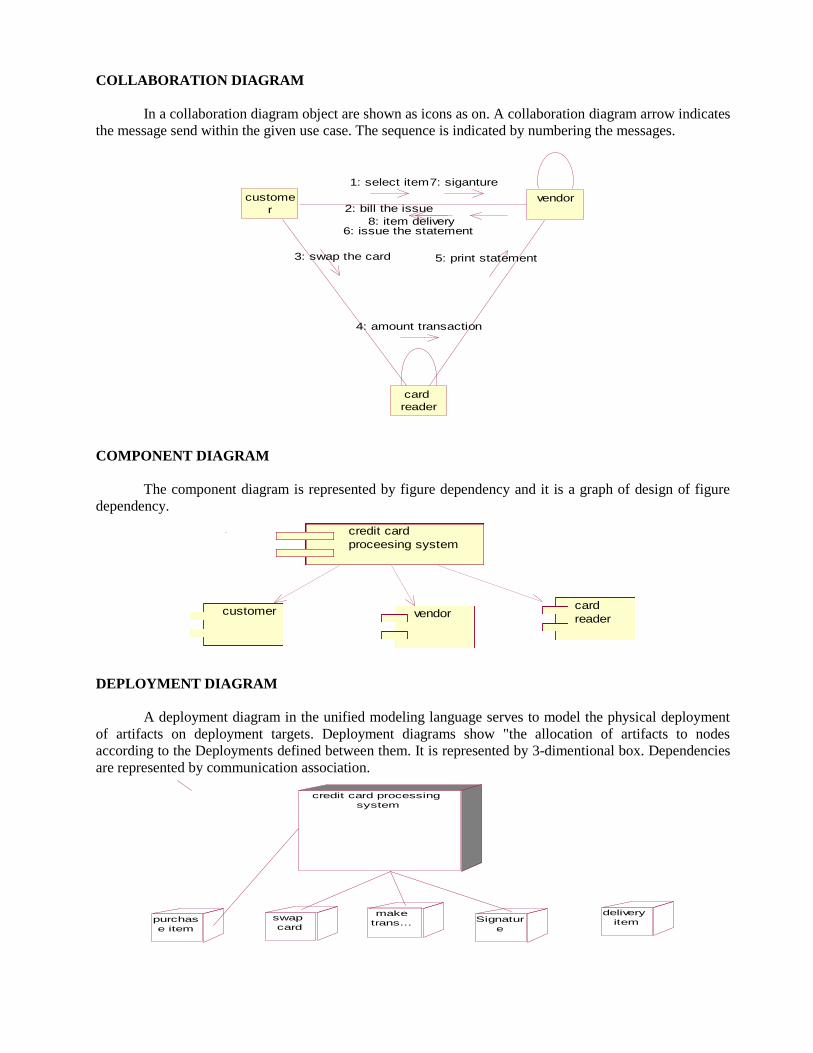
COLLABORATION DIAGRAM
In a collaboration diagram object are shown as icons as on. A collaboration diagram arrow indicates
the message send within the given use case. The sequence is indicated by numbering the messages.
custome
rvendor
card
reader
4: amount transaction
1: select item
2: bill the issue
6: issue the statement
7: siganture
8: item delivery
3: swap the card 5: print statement
COMPONENT DIAGRAM
The component diagram is represented by figure dependency and it is a graph of design of figure
dependency.
credit card
proceesing system
customer vendorcard
reader
DEPLOYMENT DIAGRAM
A deployment diagram in the unified modeling language serves to model the physical deployment
of artifacts on deployment targets. Deployment diagrams show "the allocation of artifacts to nodes
according to the Deployments defined between them. It is represented by 3-dimentional box. Dependencies
are represented by communication association.
credit card processing
system
purchas
e item
swap
card
make
trans...
delivery
itemSignatur
e
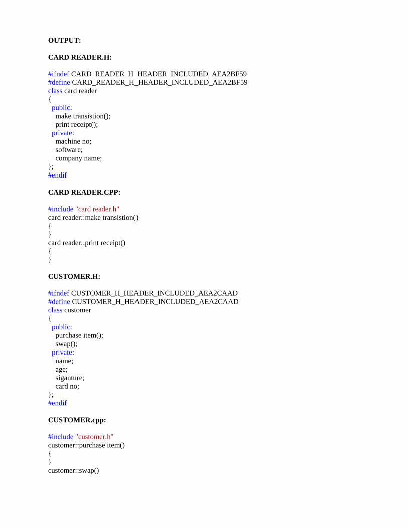
OUTPUT:
CARD READER.H:
#ifndef CARD_READER_H_HEADER_INCLUDED_AEA2BF59
#define CARD_READER_H_HEADER_INCLUDED_AEA2BF59
class card reader
{
public:
make transistion();
print receipt();
private:
machine no;
software;
company name;
};
#endif
CARD READER.CPP:
#include "card reader.h"
card reader::make transistion()
{
}
card reader::print receipt()
{
}
CUSTOMER.H:
#ifndef CUSTOMER_H_HEADER_INCLUDED_AEA2CAAD
#define CUSTOMER_H_HEADER_INCLUDED_AEA2CAAD
class customer
{
public:
purchase item();
swap();
private:
name;
age;
siganture;
card no;
};
#endif
CUSTOMER.cpp:
#include "customer.h"
customer::purchase item()
{
}
customer::swap()
{
}
VENDOR.H:
#ifndef VENDOR_H_HEADER_INCLUDED_AEA2C1B6
#define VENDOR_H_HEADER_INCLUDED_AEA2C1B6
class vendor
{
public:
make bill();
delivery item();
submit();
private:
name;
address;
machine num;
};
#endif
VENDOR.CPP:
#include "vendor.h"
vendor::make bill()
{
}
vendor::delivery item()
{
}
vendor::submit()
{
}
RESULT Thus the project to develop credit card processing system using Rational Rose Software was done
successfully.

EX.NO: 10 E-BOOKS MANAGEMENT SYSTEM
DATE:
AIM To develop a project E-Book Management system using Rational Rose Software
PROBLEM ANALYSIS AND PROJECT PLANNING
E-book Management System gives an idea about how books are maintained in the particular
websites. The books that are to be purchased, the books that are to be sold are maintained here. . Further
some additional details of the current books that is available in the store are also given. E-book
Management System in this project is done in an authorized way. The password and user id has been set
here.
PROBLEM STATEMENT
The website has to be maintained properly since the whole e-book purchase process can be
improved. E-book management in this project gives the idea about how e-books are maintained in a
particular concern. The book details which includes the number of books available, no of pages and price.
E-book management system the E-book management in this project is understood by going through the
modules that is being involved.
INTRODUCTION
E-book management gives an idea about how e-books are maintained in the particular concern. The
e-books that are to be purchased, the e-books that are to be sold are maintained here. Further some
additional details of the current e-book list that is available in the website are also given. E-book
management in this project is done in an authorized way.
SCOPE
The scope of this e-book management is to maintain the book details after the purchase and list of
reaming books available in the same book type.
UML DIAGRAMS:
USE CASE DIAGRAM
A use case is a methodology used in system analysis to identify, clarify, and organize system
requirements. The use case is made up of a set of possible sequences of interactions between systems and
users in a particular environment and related to a particular goal. It is represented using ellipse.
Actor is any external entity that makes use of the system being modelled. It is represented using stick figure
customer
login
select books
payment
database

CLASS DIAGRAM
A class diagram in the unified modeling language (UML) is a type of static structure diagram that
describes the structure of a system by showing the system's classes, their attributes, and the relationships
between the classes. It is represented using a rectangle with three compartments. Top compartment have the
class name, middle compartment the attributes and the bottom compartment with operations.
SEQUENCE DIAGRAM
A sequence diagram in Unified Modeling Language (UML) is a kind of interaction diagram that
shows how processes operate with one another and in what order. It is a construct of a Message Sequence
Chart. There are two dimensions.
1.Veritcal dimension-represent time.
2.Horizontal dimension-represent different objects.
customercustomer loginlogin databasedatabase
1: enter the name
2: enter password
3: submit
4: verification
5: incorrect username or password login again
COLLABORATION DIAGRAM
A collaboration diagram, also called a communication diagram or interaction diagram,. A
sophisticated modelling tool can easily convert a collaboration diagram into a sequence diagram and the
vice versa. A collaboration diagram resembles a flowchart that portrays the roles, functionality and
behaviour of individual objects as well as the overall operation of the system in real time.

custome
r
login
databas
e
4: incorrect username and password
1: enter name and password 2: submit
3: verification
STATE CHART DIAGRAM
The purpose of state chart diagram is to understand the algorithm involved in performing a method.
It is also called as state diagram. A state is represented as a round box, which may contain one or more
compartments. An initial state is represented as small dot. A final state is represented as circle surrounding a
small dot.
login
select the
book
buybook
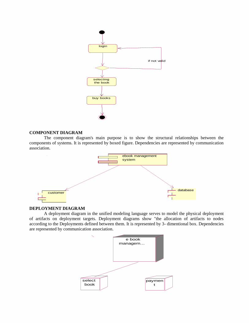
ACTIVITY DIAGRAM
Activity diagrams are graphical representations of workflows of stepwise activities and actions with
support for choice, iteration and concurrency. In the Unified Modeling Language, activity diagrams can be
used to describe the business and operational step-by-step workflows of components in a system. An
activity diagram shows the overall flow of control. An activity is shown as an rounded box containing the
name of the operation.
login
selecting
the book
buy books
if not valid
COMPONENT DIAGRAM The component diagram's main purpose is to show the structural relationships between the
components of systems. It is represented by boxed figure. Dependencies are represented by communication
association.
ebook management
system
customerdatabase
ebook management
system
customerdatabase
DEPLOYMENT DIAGRAM
A deployment diagram in the unified modeling language serves to model the physical deployment
of artifacts on deployment targets. Deployment diagrams show "the allocation of artifacts to nodes
according to the Deployments defined between them. It is represented by 3- dimentional box. Dependencies
are represented by communication association.
e book
managem...
select
bookpaymen
t
OUTPUT:
BOOKS.H:
#ifndef BOOKS_H_HEADER_INCLUDED_AEA2A1C0
#define BOOKS_H_HEADER_INCLUDED_AEA2A1C0
class books
{
public:
select();
buy();
private:
operating system;
computer architecture;
dbms;
webtechnology;
ooad;
};
#endif
BOOKS.CPP:
#include "books.h"
books::select()
{
}
books::buy()
{
}
CUSTOMER.H:
#ifndef CUSTOMER_H_HEADER_INCLUDED_AEA29C65
#define CUSTOMER_H_HEADER_INCLUDED_AEA29C65
class customer
{
public:
login();
payment();
private:
name;
address;
contact no;
};
#endif
CUSTOMER.CPP:
#include "customer.h"
customer::login()
{
}
customer::payment()
{
}
DATABASE.H:
#ifndef DATABASE_H_HEADER_INCLUDED_AEA28C6D
#define DATABASE_H_HEADER_INCLUDED_AEA28C6D
class database
{
public:
store();
private:
operation;
};
#endif
DATABASE.CPP:
#include "database.h"
database::store()
{
}
RESULT Thus the project to develop E-book Management System using Rational Rose Software was done
successfully
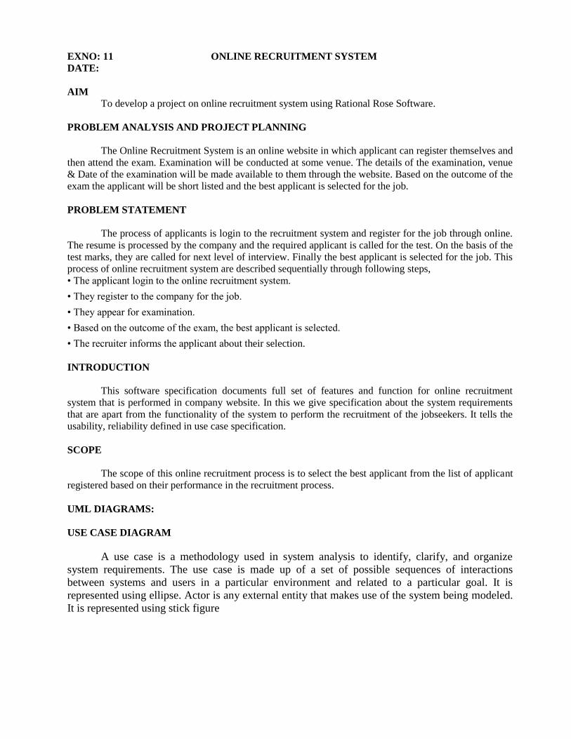
EXNO: 11 ONLINE RECRUITMENT SYSTEM
DATE:
AIM To develop a project on online recruitment system using Rational Rose Software.
PROBLEM ANALYSIS AND PROJECT PLANNING
The Online Recruitment System is an online website in which applicant can register themselves and
then attend the exam. Examination will be conducted at some venue. The details of the examination, venue
& Date of the examination will be made available to them through the website. Based on the outcome of the
exam the applicant will be short listed and the best applicant is selected for the job.
PROBLEM STATEMENT
The process of applicants is login to the recruitment system and register for the job through online.
The resume is processed by the company and the required applicant is called for the test. On the basis of the
test marks, they are called for next level of interview. Finally the best applicant is selected for the job. This
process of online recruitment system are described sequentially through following steps,
• The applicant login to the online recruitment system.
• They register to the company for the job.
• They appear for examination.
• Based on the outcome of the exam, the best applicant is selected.
• The recruiter informs the applicant about their selection.
INTRODUCTION
This software specification documents full set of features and function for online recruitment
system that is performed in company website. In this we give specification about the system requirements
that are apart from the functionality of the system to perform the recruitment of the jobseekers. It tells the
usability, reliability defined in use case specification.
SCOPE
The scope of this online recruitment process is to select the best applicant from the list of applicant
registered based on their performance in the recruitment process.
UML DIAGRAMS:
USE CASE DIAGRAM
A use case is a methodology used in system analysis to identify, clarify, and organize
system requirements. The use case is made up of a set of possible sequences of interactions
between systems and users in a particular environment and related to a particular goal. It is
represented using ellipse. Actor is any external entity that makes use of the system being modeled.
It is represented using stick figure

CLASS DIAGRAM
A class diagram in the unified modeling language (UML) is a type of static structure diagram that
describes the structure of a system by showing the system's classes, their attributes, and the relationships
between the classes. It is represented using a rectangle with three compartments. Top compartment have the
class name, middle compartment the attributes and the bottom compartment with operations.
SEQUENCE DIAGRAM A sequence diagram in Unified Modeling Language (UML) is a kind of interaction diagram that
shows how processes operate with one another and in what order. It is a construct of a Message Sequence
Chart. There are two dimensions.
1.Veritcal dimension-represent time.
2.Horizontal dimension-represent different objects.
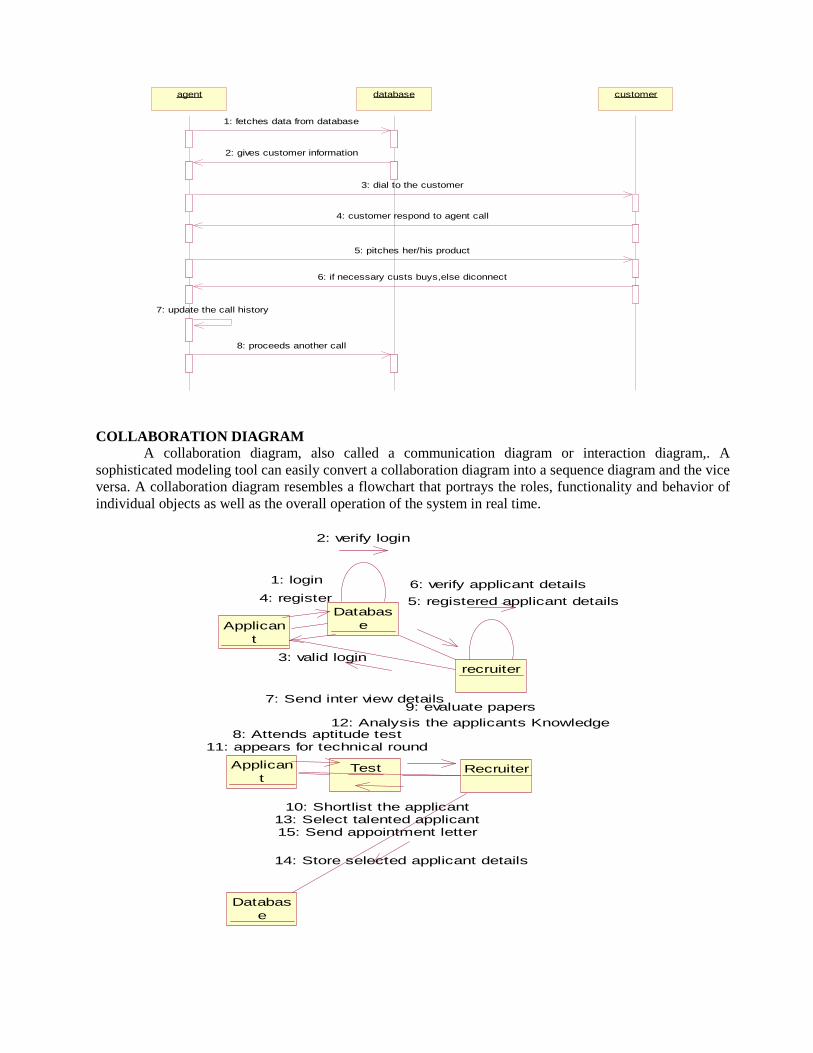
agentagent databasedatabase customercustomer
1: fetches data from database
2: gives customer information
3: dial to the customer
4: customer respond to agent call
5: pitches her/his product
6: if necessary custs buys,else diconnect
7: update the call history
8: proceeds another call
COLLABORATION DIAGRAM
A collaboration diagram, also called a communication diagram or interaction diagram,. A
sophisticated modeling tool can easily convert a collaboration diagram into a sequence diagram and the vice
versa. A collaboration diagram resembles a flowchart that portrays the roles, functionality and behavior of
individual objects as well as the overall operation of the system in real time.
5: registered applicant details
Applican
t
Databas
e
recruiter
Applican
tTest Recruiter
Databas
e
2: verify login
6: verify applicant details1: login
4: register
3: valid login
7: Send inter view details
8: Attends aptitude test11: appears for technical round
9: evaluate papers
12: Analysis the applicants Knowledge
10: Shortlist the applicant13: Select talented applicant15: Send appointment letter
14: Store selected applicant details
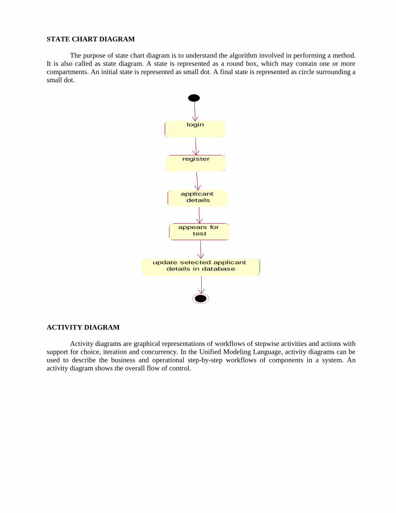
STATE CHART DIAGRAM
The purpose of state chart diagram is to understand the algorithm involved in performing a method.
It is also called as state diagram. A state is represented as a round box, which may contain one or more
compartments. An initial state is represented as small dot. A final state is represented as circle surrounding a
small dot.
login
register
applicant
details
appears for
test
update selected applicant
details in database
ACTIVITY DIAGRAM
Activity diagrams are graphical representations of workflows of stepwise activities and actions with
support for choice, iteration and concurrency. In the Unified Modeling Language, activity diagrams can be
used to describe the business and operational step-by-step workflows of components in a system. An
activity diagram shows the overall flow of control.
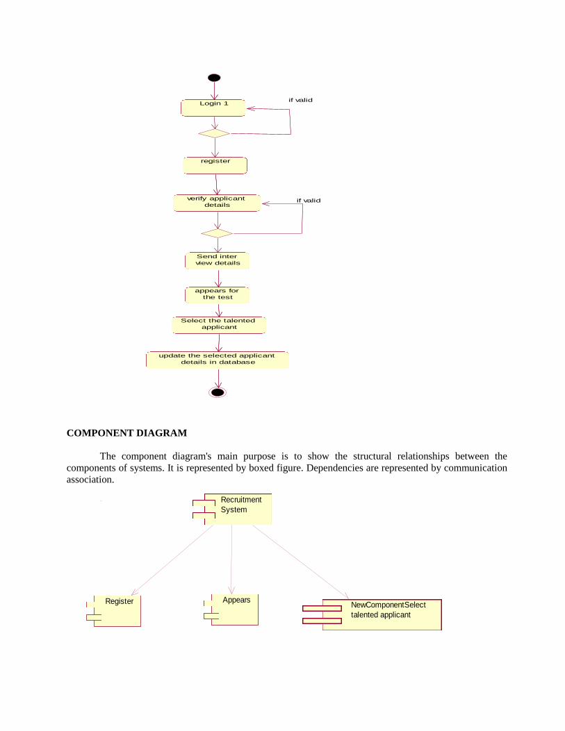
Login 1
register
verify applicant
details
Send inter
view details
appears for
the test
Select the talented
applicant
update the selected applicant
details in database
if valid
if valid
COMPONENT DIAGRAM
The component diagram's main purpose is to show the structural relationships between the
components of systems. It is represented by boxed figure. Dependencies are represented by communication
association.
Recruitment
System
Register AppearsNewComponentSelect
talented applicant

DEPLOYMENT DIAGRAM
A deployment diagram in the unified modeling language serves to model the physical deployment
of artifacts on deployment targets. Deployment diagrams show "the allocation of artifacts to nodes
according to the Deployments defined between them. It is represented by 3- dimentional box. Dependencies
are represented by communication association.
select talented
applicant1
Online recruitment
system
RegisterAppears
for test
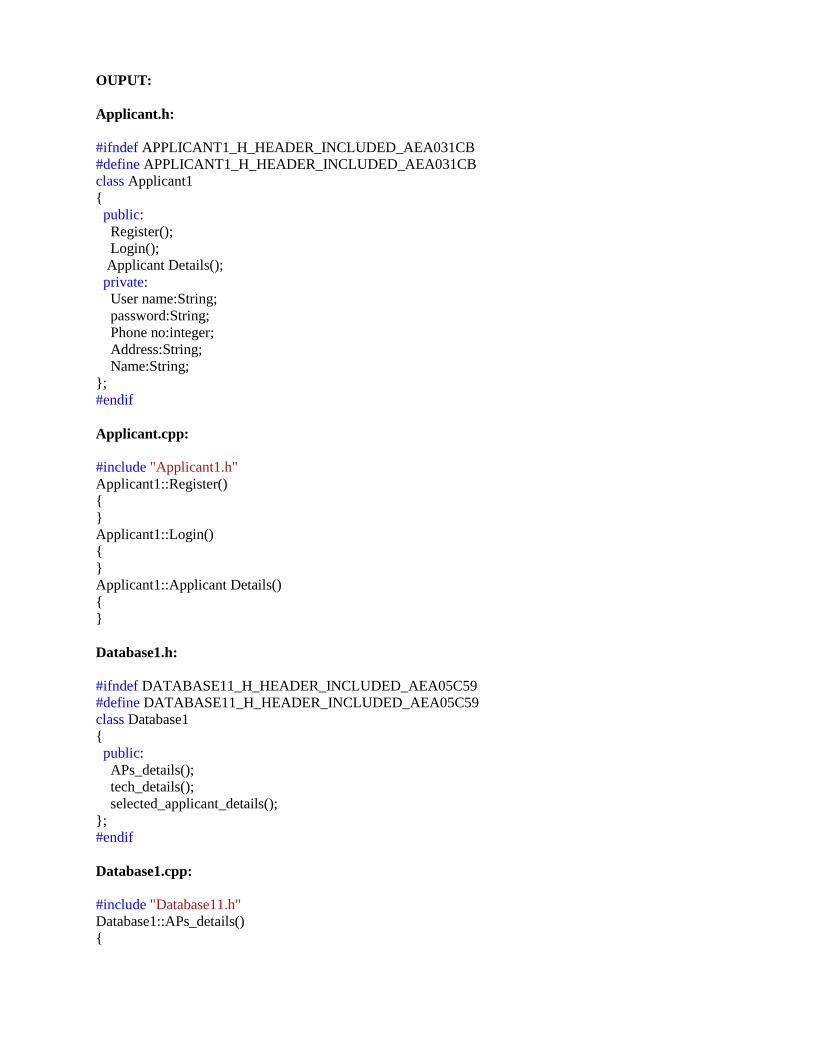
OUPUT:
Applicant.h:
#ifndef APPLICANT1_H_HEADER_INCLUDED_AEA031CB
#define APPLICANT1_H_HEADER_INCLUDED_AEA031CB
class Applicant1
{
public:
Register();
Login();
Applicant Details();
private:
User name:String;
password:String;
Phone no:integer;
Address:String;
Name:String;
};
#endif
Applicant.cpp:
#include "Applicant1.h"
Applicant1::Register()
{
}
Applicant1::Login()
{
}
Applicant1::Applicant Details()
{
}
Database1.h:
#ifndef DATABASE11_H_HEADER_INCLUDED_AEA05C59
#define DATABASE11_H_HEADER_INCLUDED_AEA05C59
class Database1
{
public:
APs_details();
tech_details();
selected_applicant_details();
};
#endif
Database1.cpp:
#include "Database11.h"
Database1::APs_details()
{

}
Database1::tech_details()
{
}
Database1::selected_applicant_details()
{
}
Recruiter1.h:
#ifndef RECRUITER1_H_HEADER_INCLUDED_AEA06A89
#define RECRUITER1_H_HEADER_INCLUDED_AEA06A89
class Recruiter1
{
public:
APS_test();
APS1_test();
Tech_Round();
Tech1_Round();
private:
Name:String;
Destination:String;
Phone no:integer;
Marks_in_Aps:Integer;
Marks_in_tech:Integer;
};
#endif
Recruiter.cpp:
#include "Recruiter1.h"
Recruiter1::APS_test()
{
}
Recruiter1::APS1_test()
{
}
Recruiter1::Tech_Round()
{
}
Recruiter1::Tech1_Round()
{
}
RESULT Thus the project to develop online recruitment system using Rational Rose Software was done
successfully.
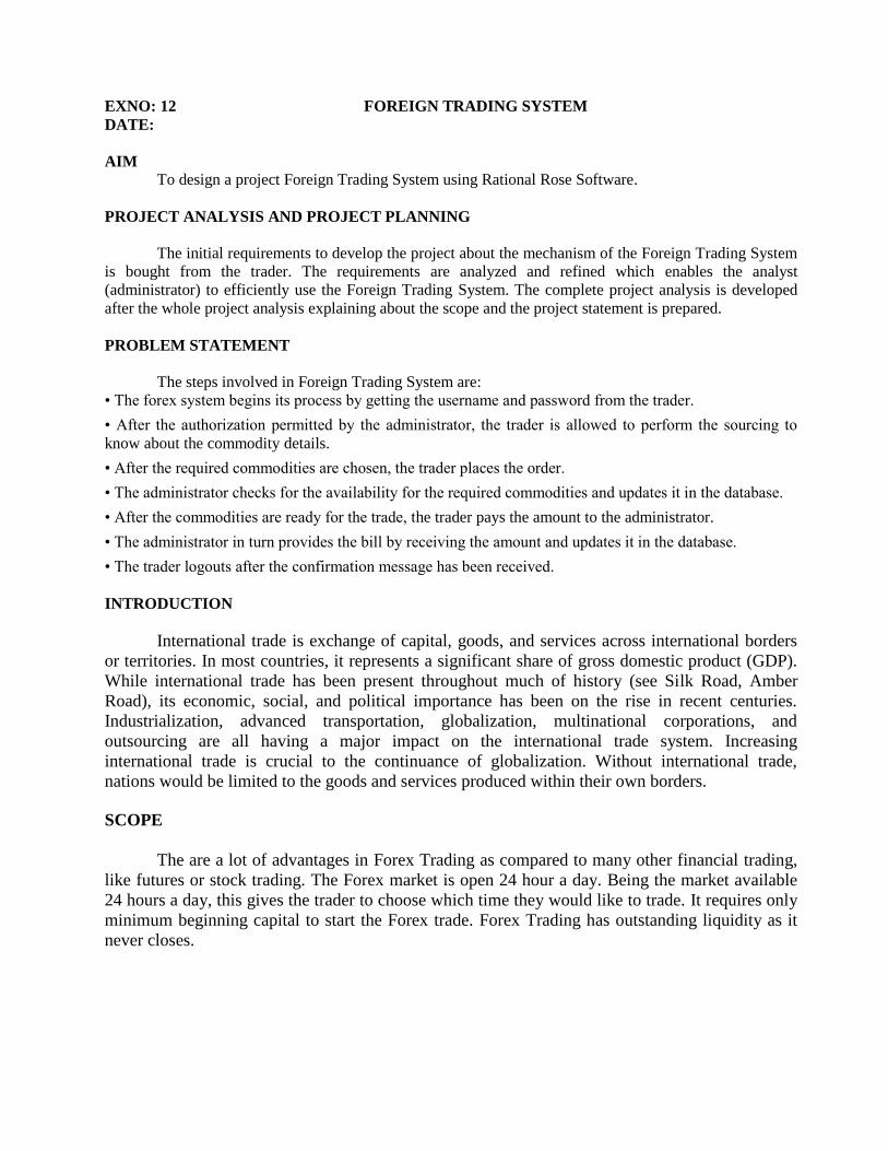
EXNO: 12 FOREIGN TRADING SYSTEM
DATE:
AIM To design a project Foreign Trading System using Rational Rose Software.
PROJECT ANALYSIS AND PROJECT PLANNING
The initial requirements to develop the project about the mechanism of the Foreign Trading System
is bought from the trader. The requirements are analyzed and refined which enables the analyst
(administrator) to efficiently use the Foreign Trading System. The complete project analysis is developed
after the whole project analysis explaining about the scope and the project statement is prepared.
PROBLEM STATEMENT
The steps involved in Foreign Trading System are:
• The forex system begins its process by getting the username and password from the trader.
• After the authorization permitted by the administrator, the trader is allowed to perform the sourcing to
know about the commodity details.
• After the required commodities are chosen, the trader places the order.
• The administrator checks for the availability for the required commodities and updates it in the database.
• After the commodities are ready for the trade, the trader pays the amount to the administrator.
• The administrator in turn provides the bill by receiving the amount and updates it in the database.
• The trader logouts after the confirmation message has been received.
INTRODUCTION
International trade is exchange of capital, goods, and services across international borders
or territories. In most countries, it represents a significant share of gross domestic product (GDP).
While international trade has been present throughout much of history (see Silk Road, Amber
Road), its economic, social, and political importance has been on the rise in recent centuries.
Industrialization, advanced transportation, globalization, multinational corporations, and
outsourcing are all having a major impact on the international trade system. Increasing
international trade is crucial to the continuance of globalization. Without international trade,
nations would be limited to the goods and services produced within their own borders.
SCOPE
The are a lot of advantages in Forex Trading as compared to many other financial trading,
like futures or stock trading. The Forex market is open 24 hour a day. Being the market available
24 hours a day, this gives the trader to choose which time they would like to trade. It requires only
minimum beginning capital to start the Forex trade. Forex Trading has outstanding liquidity as it
never closes.

UML DIAGRAMS:
USECASE DIAGRAM:
A use case diagram purpose is to present a graphical overview of the functionality provided by the
system in terms of actors, their goals, and any dependencies between those use cases.
A use case is an interaction between users and a system in a particular environment. It captures the goal of
the users and the responsibility of the system to the user. It is represented using ellipse. Actor is a user
playing a role with respect to the system. A single actor may perform many usecases. It is represented using
a stick figure along with a label.
Login
Sourcing
Place order
Pay
Trader
Logout
Bill
Administrator
update
CLASS DIAGRAM
A class diagram is a type of static structure diagram that describes the structure of a system. The
classes in the class diagram represent both the main objects and or interactions in the application.
The class diagram is represented using rectangular boxes each of which contains three parts:
• The upper part holds the name of the class.
• The middle part contains the attributes of the class.
• The bottom part gives the operations or methods the class undertakes
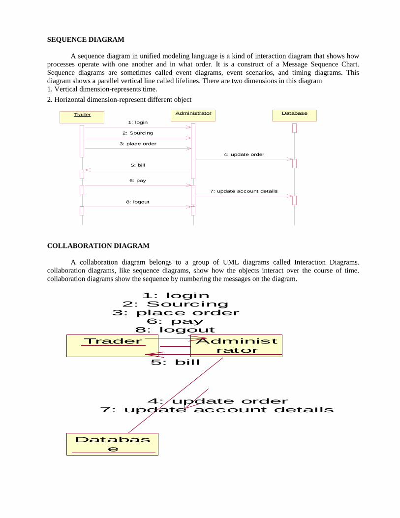
SEQUENCE DIAGRAM
A sequence diagram in unified modeling language is a kind of interaction diagram that shows how
processes operate with one another and in what order. It is a construct of a Message Sequence Chart.
Sequence diagrams are sometimes called event diagrams, event scenarios, and timing diagrams. This
diagram shows a parallel vertical line called lifelines. There are two dimensions in this diagram
1. Vertical dimension-represents time.
2. Horizontal dimension-represent different object
TraderTrader AdministratorAdministrator DatabaseDatabase
1: login
2: Sourcing
3: place order
4: update order
5: bill
6: pay
7: update account details
8: logout
COLLABORATION DIAGRAM
A collaboration diagram belongs to a group of UML diagrams called Interaction Diagrams.
collaboration diagrams, like sequence diagrams, show how the objects interact over the course of time.
collaboration diagrams show the sequence by numbering the messages on the diagram.
Trader Administ
rator
Databas
e
1: login2: Sourcing
3: place order6: pay
8: logout
5: bill
4: update order7: update account details

STATE CHART DIAGRAM
The state chart is used to model dynamic nature of a system. They define different states of an
object during its lifetime. And these states are changed by events. So these diagrams are useful for reactive
systems i.e.., a system that responds to external or internal events. It describes the flow of control from one
state to other state. The initial state is represented using the small dot. The final state is represented using a
circle surrounded by a small dot.
Administ
rator
Foriegn Trading
System
Trader
ACTIVITY DIAGRAM
This diagram represents the graphical representation of workflows of stepwise activities and actions
with support for choice, iteration and concurrency. It shows the overall flow of control.
login
Sourcing
place order
Bill
pay
logout
COMPONENT DIAGRAM
The component diagram's main purpose is to show the structural relationships between the
components of systems. It is represented by boxed figure. Dependencies are represented by communication
association.
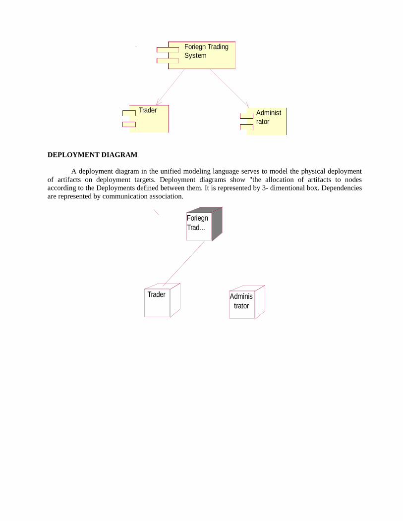
Administ
rator
Foriegn Trading
System
Trader
DEPLOYMENT DIAGRAM
A deployment diagram in the unified modeling language serves to model the physical deployment
of artifacts on deployment targets. Deployment diagrams show "the allocation of artifacts to nodes
according to the Deployments defined between them. It is represented by 3- dimentional box. Dependencies
are represented by communication association.
Trader
Foriegn
Trad...
Adminis
trator
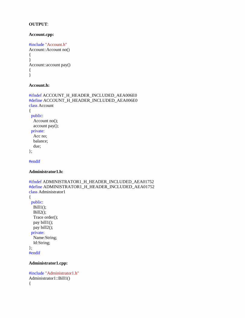
OUTPUT:
Account.cpp:
#include "Account.h"
Account::Account no()
{
}
Account::account pay()
{
}
Account.h:
#ifndef ACCOUNT_H_HEADER_INCLUDED_AEA006E0
#define ACCOUNT_H_HEADER_INCLUDED_AEA006E0
class Account
{
public:
Account no();
account pay();
private:
Acc no;
balance;
due;
};
#endif
Administrator1.h:
#ifndef ADMINISTRATOR1_H_HEADER_INCLUDED_AEA01752
#define ADMINISTRATOR1_H_HEADER_INCLUDED_AEA01752
class Administrator1
{
public:
Bill1();
Bill2();
Trace order();
pay bill1();
pay bill2();
private:
Name:String;
Id:String;
};
#endif
Administrator1.cpp:
#include "Administrator1.h"
Administrator1::Bill1()
{
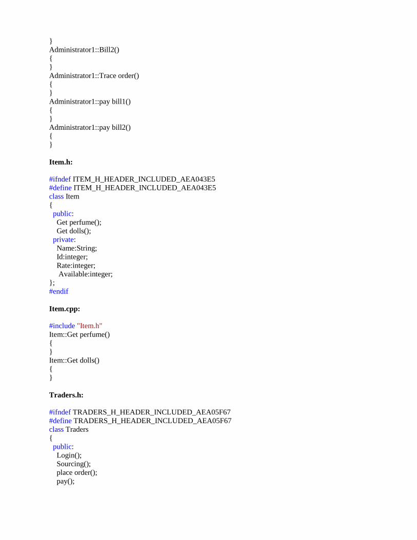
}
Administrator1::Bill2()
{
}
Administrator1::Trace order()
{
}
Administrator1::pay bill1()
{
}
Administrator1::pay bill2()
{
}
Item.h:
#ifndef ITEM_H_HEADER_INCLUDED_AEA043E5
#define ITEM_H_HEADER_INCLUDED_AEA043E5
class Item
{
public:
Get perfume();
Get dolls();
private:
Name:String;
Id:integer;
Rate:integer;
Available:integer;
};
#endif
Item.cpp:
#include "Item.h"
Item::Get perfume()
{
}
Item::Get dolls()
{
}
Traders.h:
#ifndef TRADERS_H_HEADER_INCLUDED_AEA05F67
#define TRADERS_H_HEADER_INCLUDED_AEA05F67
class Traders
{
public:
Login();
Sourcing();
place order();
pay();

logout();
private:
Username:String;
Sourcing:String;
Account no:integer;
};
#endif
Traders.cpp:
#include "Traders.h"
Traders::Login()
{
}
Traders::Sourcing()
{
}
Traders::place order()
{
}
Traders::pay()
{
}
Traders::logout()
{
}
RESULT Thus the project to develop foreign trading system using Rational Rose software was done
successfully.
EXNO: 13 CONFERENCE MANAGEMENT SYSTEM
DATE:
AIM To develop a project on Conference management system using Rational Rose Software
PROBLEM ANALYSIS AND PROJECT PLANNING
The Conference Management System is an online website in which candidate can submit the paper
and register themselves and then attend the conference. The paper will be reviewed. The details of the
conference, date and time will be made available to them through the website. After getting the
confirmation details the candidate should submit the revised and camera ready paper. Then the registration
process will be done.
PROBLEM STATEMENT
The process of the candidates is to login the conference system and submit the paper through
online. Then the reviewer reviews the paper and sends the acknowledgement to the candidate either paper
selected or rejected. This process of on conference management system are described sequentially through
following steps,
• The candidate login to the conference management system.
• The paper title is submitted.
• The paper is been reviewed by the reviewer.
• The reviewer sends acknowledgement to the candidate.
• Based on the selection, the best candidate is selected.
• Finally the candidate registers all details.
INTRODUCTION
This software specification document consist full set of features and function for online conference
management system. In this we give specification about the system requirements that are apart from the
functionality of the system to perform the candidate paper valuation. It tells the usability, reliability defined
in use case specification.
SCOPE
The scope of this conference management process is to select the best candidate from the list of
candidates based on their performance in the process.
UML DIAGRAMS:
USE CASE DIAGRAM
A use case is a methodology used in system analysis to identify, clarify, and organize system
requirements. The use case is made up of a set of possible sequences of interactions between systems and
users in a particular environment and related to a particular goal. It is represented using ellipse.
Actor is any external entity that makes use of the system being modeled. It is represented using stick figure

candidate
paper submission
review the paper
paper confirmation details
revised & camera ready paper
submission
reviewer
registration
login
database
CLASS DIAGRAM
A class diagram in the unified modeling language (UML) is a type of static structure diagram that
describes the structure of a system by showing the system's classes, their attributes, and the relationships
between the classes. It is represented using a rectangle with three compartments. Top compartment have the
class name, middle compartment the attributes and the bottom compartment with operations.
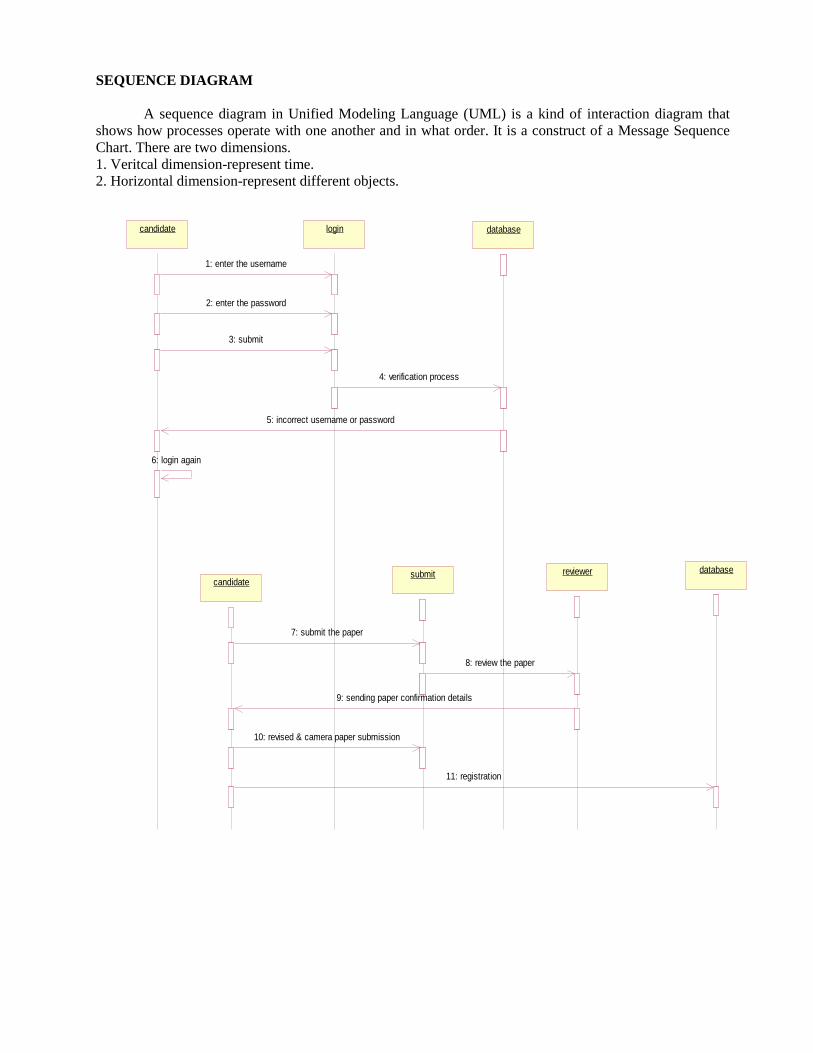
SEQUENCE DIAGRAM
A sequence diagram in Unified Modeling Language (UML) is a kind of interaction diagram that
shows how processes operate with one another and in what order. It is a construct of a Message Sequence
Chart. There are two dimensions.
1. Veritcal dimension-represent time.
2. Horizontal dimension-represent different objects.
candidatecandidate
candidatecandidate
loginlogin
submitsubmit
databasedatabase
reviewerreviewer databasedatabase
1: enter the username
2: enter the password
3: submit
4: verification process
5: incorrect username or password
6: login again
7: submit the paper
8: review the paper
9: sending paper confirmation details
10: revised & camera paper submission
11: registration
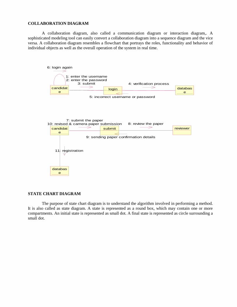
COLLABORATION DIAGRAM
A collaboration diagram, also called a communication diagram or interaction diagram,. A
sophisticated modeling tool can easily convert a collaboration diagram into a sequence diagram and the vice
versa. A collaboration diagram resembles a flowchart that portrays the roles, functionality and behavior of
individual objects as well as the overall operation of the system in real time.
candidat
elogin databas
e
candidat
e
submit reviewer
databas
e
6: login again
1: enter the username2: enter the password
3: submit 4: verification process
5: incorrect username or password
7: submit the paper10: revised & camera paper submission
11: registration
8: review the paper
9: sending paper confirmation details
STATE CHART DIAGRAM
The purpose of state chart diagram is to understand the algorithm involved in performing a method.
It is also called as state diagram. A state is represented as a round box, which may contain one or more
compartments. An initial state is represented as small dot. A final state is represented as circle surrounding a
small dot.
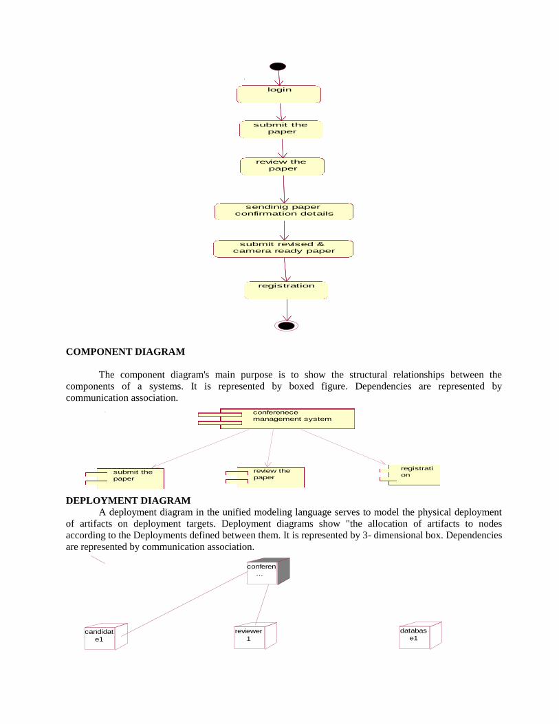
login
submit the
paper
review the
paper
sendinig paper
confirmation details
submit revised &
camera ready paper
registration
COMPONENT DIAGRAM
The component diagram's main purpose is to show the structural relationships between the
components of a systems. It is represented by boxed figure. Dependencies are represented by
communication association.
conferenece
management system
submit the
paper
review the
paper
registrati
on
DEPLOYMENT DIAGRAM
A deployment diagram in the unified modeling language serves to model the physical deployment
of artifacts on deployment targets. Deployment diagrams show "the allocation of artifacts to nodes
according to the Deployments defined between them. It is represented by 3- dimensional box. Dependencies
are represented by communication association.
conferen
...
candidat
e1
reviewer
1
databas
e1
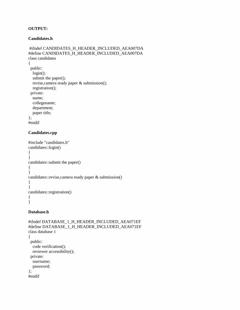
OUTPUT:
Candidates.h
#ifndef CANDIDATES_H_HEADER_INCLUDED_AEA007DA
#define CANDIDATES_H_HEADER_INCLUDED_AEA007DA
class candidates
{
public:
login();
submit the paper();
revise,camera ready paper & submission();
registration();
private:
name;
collegename;
department;
paper title;
};
#endif
Candidates.cpp
#include "candidates.h"
candidates::login()
{
}
candidates::submit the paper()
{
}
candidates::revise,camera ready paper & submission()
{
}
candidates::registration()
{
}
Database.h
#ifndef DATABASE_1_H_HEADER_INCLUDED_AEA071EF
#define DATABASE_1_H_HEADER_INCLUDED_AEA071EF
class database 1
{
public:
code verification();
reviewer accessibility();
private:
username;
password;
};
#endif
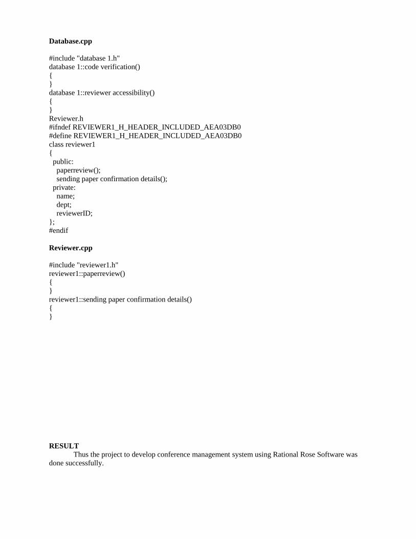
Database.cpp
#include "database 1.h"
database 1::code verification()
{
}
database 1::reviewer accessibility()
{
}
Reviewer.h
#ifndef REVIEWER1_H_HEADER_INCLUDED_AEA03DB0
#define REVIEWER1_H_HEADER_INCLUDED_AEA03DB0
class reviewer1
{
public:
paperreview();
sending paper confirmation details();
private:
name;
dept;
reviewerID;
};
#endif
Reviewer.cpp
#include "reviewer1.h"
reviewer1::paperreview()
{
}
reviewer1::sending paper confirmation details()
{
}
RESULT Thus the project to develop conference management system using Rational Rose Software was
done successfully.

EXNO: 14 BUSINESS PROCESS OUTSOURCING MANAGEMENT SYSTEM
DATE:
AIM To develop a project Business process outsourcing(BPO) management system using Rational Rose
software.
PROBLEM ANALYSIS AND PROJECT PLANNING
Generally outsourcing can be defined as an organization entering into a contract with another
organization to operate and managed one or more of its business processes. There are many problems faced
by the BPO one among them is meeting their targets and leaving the concern very often and switch to
another company. In this project we deal with the inbound system of the BPO. In inbound system the agent
calls the customer from his database to sell his product.
PROBLEM STATEMENT
In this BPO inbound system , the process undergoing is that the agent tries to sell his product so
that the agent gets the details of the customer from the database and pitches about his product and makes the
sales successful. The communication is done through the telephone. Telephone is the major component
used for this customer satisfaction service. The steps are as follows:
• The agent login to the website and enters the username and password .It checks for authorization.
• If the username and password is correct, it allows the agent to get the details of the customer from the
database.
• Now the agent makes the call to the customer and pitches about the product.
• If the customer is satisfied, agent sells the product else disconnects the call.
• Agent proceeds with another call.
INTRODUCTION
BPO is typically categorized into back office outsourcing-which includes internal business
functions such as human resources or finance and accounting, and front office outsourcing-which includes
customer related services such as contact center services. BPO that is contracted outside a company’s
country is called offshore outsourcing.BPO that is contracted to a company’s neighboring country is called
near shore outsourcing. Given the proximity of BPO to the information technology industry, it is
categorized as an information technology enabled service or ITES. Knowledge process outsourcing (KPO)
and legal process outsourcing (LPO) are some of the sub-segments of business process outsourcing
industry. In the following SRS the front office outsourcing is explained in detail.
SCOPE
Developing a good BPO management system.BPO is a way in which it helps to increase companies
flexibility. As part of BPO, documents need to be managed between the outsourcing company and the
offshore company. Multiple clients need to be managed by the BPO company.
UML DIAGRAMS:
USE CASE DIAGRAM
A use case is a methodology used in system analysis to identify, clarify, and organize system
requirements. The use case is made up of a set of possible sequences of interactions between systems
and users in a particular environment and related to a particular goal. It is represented using ellipse.

Actor is any external entity that makes use of the system being modeled. It is represented using stick
figure
login
searches thedatabase for
customer data
agent pitches his product
process agent
agent processed another call
database
gives the phone ni customer data
agent dial up the record
customer responds to agent call
respond to agent if cust
isinterested
CLASS DIAGRAM
A class diagram in the unified modeling language (UML) is a type of static structure diagram that
describes the structure of a system by showing the system's classes, their attributes, and the relationships
between the classes. It is represented using a rectangle with three compartments. Top compartment have the
class name, middle compartment the attributes and the bottom compartment with operations.
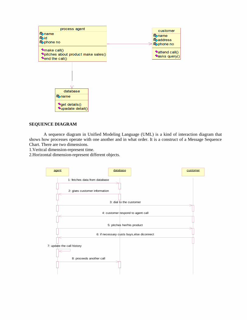
SEQUENCE DIAGRAM
A sequence diagram in Unified Modeling Language (UML) is a kind of interaction diagram that
shows how processes operate with one another and in what order. It is a construct of a Message Sequence
Chart. There are two dimensions.
1.Veritcal dimension-represent time.
2.Horizontal dimension-represent different objects.
agentagent databasedatabase customercustomer
1: fetches data from database
2: gives customer information
3: dial to the customer
4: customer respond to agent call
5: pitches her/his product
6: if necessary custs buys,else diconnect
7: update the call history
8: proceeds another call

COLLABORATION DIAGRAM
A collaboration diagram, also called a communication diagram or interaction diagram,. A
sophisticated modelling tool can easily convert a collaboration diagram into a sequence diagram and the
vice versa. A collaboration diagram resembles a flowchart that portrays the roles, functionality and
behaviour of individual objects as well as the overall operation of the system in real time.
7: proceed another call
agent custome
r
databas
e
update the history
1: fetches data from database
2: give customer information
3: dial the customer
4: customer respond to agent call
5: pitches his/her product
6: if necessary customer buys,else diconnect
STATE CHART DIAGRAM
The purpose of state chart diagram is to understand the algorithm involved in performing a method.
It is also called as state diagram. A state is represented as a round box, which may contain one or more
compartments. An initial state is represented as small dot. A final state is represented as circle surrounding a
small dot.
login
fetches data
form database
calls the
customer
pitches the
product
sales the
product
proceed
another call

COMPONENT DIAGRAM
The component diagram's main purpose is to show the structural relationships between the
components of systems. It is represented by boxed figure. Dependencies are represented by communication
association.
BPO Processing
management
calls the
cutomerpitches his/her
productmake
sale
DEPLOYMENT DIAGRAM
A deployment diagram in the unified modeling language serves to model the physical deployment
of artifacts on deployment targets. Deployment diagrams show "the allocation of artifacts to nodes
according to the Deployments defined between them. It is represented by 3- dimensional box. Dependencies
are represented by communication association.
BPO process
management system
agentcustom
er
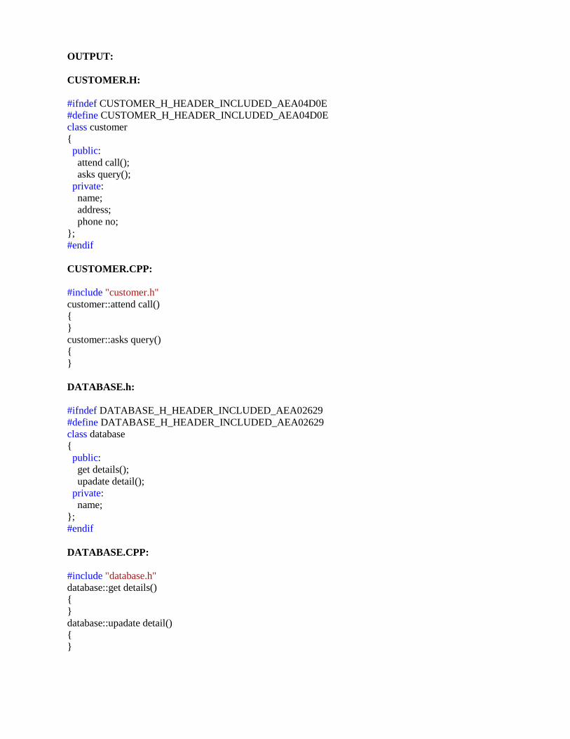
OUTPUT:
CUSTOMER.H:
#ifndef CUSTOMER_H_HEADER_INCLUDED_AEA04D0E
#define CUSTOMER_H_HEADER_INCLUDED_AEA04D0E
class customer
{
public:
attend call();
asks query();
private:
name;
address;
phone no;
};
#endif
CUSTOMER.CPP:
#include "customer.h"
customer::attend call()
{
}
customer::asks query()
{
}
DATABASE.h:
#ifndef DATABASE_H_HEADER_INCLUDED_AEA02629
#define DATABASE_H_HEADER_INCLUDED_AEA02629
class database
{
public:
get details();
upadate detail();
private:
name;
};
#endif
DATABASE.CPP:
#include "database.h"
database::get details()
{
}
database::upadate detail()
{
}

PROCESSAGENT.h:
#ifndef PROCESS_AGENT_H_HEADER_INCLUDED_AEA04D17
#define PROCESS_AGENT_H_HEADER_INCLUDED_AEA04D17
class process agent
{
public:
make call();
pitches about product make sales();
end the call();
private:
name;
id;
phone no;
};
#endif
PROCESSAGENT.CPP:
#include "process agent.h"
process agent::make call()
{
}
process agent::pitches about product make sales()
{
}
process agent::end the call()
{
}
RESULT Thus the project to develop BPO management system using Rational Rose Software and was done
successfully