regional district of kitimat-stikine to: from: itt no. 16 ... · or only the power supply and...
TRANSCRIPT

ITT No. FR16-001 Addendum #1 ____________________________________________________________________________________________
Page 1
Regional District of Kitimat-Stikine
Construction Services for the Thornhill Transfer Station Contract To: Posted on BC Bid and RDKS’s website From: Mircea L. Cvaci P.Eng Vice president, SHA Ref: ITT No. 16-001 Date: February 16, 2016 Pages: 4 Pages including this cover page COMMENTS: Addendum #1 is attached hereto. Please take note that the Regional District of Kitimat-Stikine has issued the attached Addendum Number 1 for Invitation to Tender Number: 16-001. This Addendum includes the following: Attendance list of the Mandatory Bidder’s Meeting – Appendix 1 Questions received from contractors Revised Electrical Drawings – Dwg # 14040-1301 to Dwg # 14040 -1305 – Appendix 2 Revised EMP dated February 5, 2016 – Appendix 3

ITT No. FR16-001 Addendum #1 ____________________________________________________________________________________________
Page 2
Regional District of Kitimat-Stikine
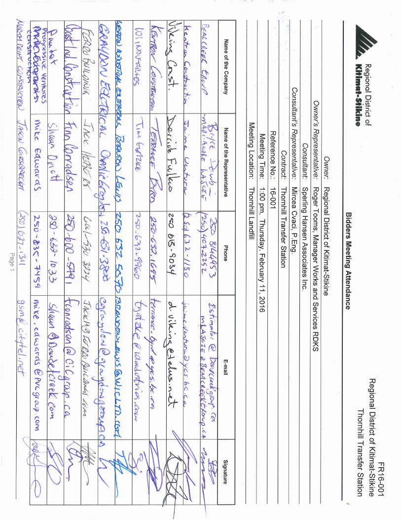
Construction Services for the Thornhill Transfer Station Contract This Addendum forms part of the Contract documents and is to be read, interpreted, co-ordinated with all other parts. The cost of all contained herein is to be included in the contract sum. The following revisions supersede the information contained in the original drawings and specifications issued for the above-named project to the extent referenced and become part thereof. The attendance list of the bidder’s that attended the mandatory bidders meeting, at Thornhill Landfill, on Thursday, February 11, 2016 is attached as Appendix 1
Questions and Answers for Bidder’s Meeting
The bidders who attended the mandatory bidders meeting raised the following questions: Q1: For alternate supply, how close to specs (scale) do you need? Instruction is to bid on specs in tender documents and can offer alternatives in provisional items. A1: The alternate should satisfactorily accomplish the intent of the design. We will review alternates to determine applicability. Q2: Is it acceptable (alternatives such as scale) if the foundation changes with the scale type if offered as provisional? A2: The foundation design must be revised to meet the alternative scale requirements. The cost associated with the redesigning of the scale foundation must be included in the Alternate bid. The scale and revised foundation design must satisfy the intention of the design.
Q3: Is there restriction on the hours of work on site? A3: There are no hour restrictions. Please refer to SGC.1 Hours of Work; Work Areas under Schedule A 8.2 Supplementary General Conditions Q4: Phase of electricity – comment that 3 phase not in area. A4: Please refer to the revised electrical drawings enclosed in Appendix 2 Q5: CO and Smoke detectors – where are they to be installed and how many? A5: Please refer to the revised electrical drawings enclosed in Appendix 2 Q6: Will the lock blocks supplied be on site? A6: Yes, the lock blocks will be supplied on site.
ITT No. FR16-001 Addendum #1 ____________________________________________________________________________________________
Page 3
Q7: Are all the lock blocks owners supplied? A7: Yes, all lock blocks are owner supplied. Q8: Are the card readers stand alone or tied back into a system? A8: Yes the card readers are tied back into a system Q9: Is the transfer station building heated? A9: No, the transfer station building is not heated. Q10: Are all questions to be directed to SHA? A10: Yes, direct all questions to SHA. For fax revision on or before closing day, please use the following fax number: 604-986-7734. Q11: Owner to enter codes on billing software? A11: Yes, the owner will enter the billing codes. Q12: What are the depths associated with the paving area? Square footage is provided but not the depths. A12: The provisional asphalt paving depth shall be 200 mm. Additional Questions Received Q13: For bonding purposes, are you able to provide the budgetary costs so I can get our bonding facility underway. A13: Budgetary costs are not available. For bonding requirements, please refer to section 5.1 of the Form of Contract. Q14: The gate as shown has one gate that provides entry and exit control for both lanes. I see readers are required for both directions. I would like to propose the use of 2 smaller barrier gates. A14: A two gate option can be included as part of the alternate bid. Q15: DWG. 14040-1201 indicates (2) surveillance cameras at the scale house, and DWG. 14040-1303 indicates (1) camera at the scale house. However, Division 28 Specifications indicates (1) camera at the scale house and (1) camera at the transfer station building. Can you please clarify which are the correct locations? A15: Please refer to the revised electrical drawings enclosed in Appendix 2. Revise drawings include 1 camera at the scale, 1 at the bins area and one at the transfer station. Q16: DWG. TC100884, Powercell PDX Standard Wiring Diagram & Lightning Protection; Are we to include in our bid the installation and termination of vendor supplied electrical material and equipment? Or only the power supply and grounding for vendor supplied electrical material and equipment? A16: Everything to be included to provide a ready to use system.
ITT No. FR16-001 Addendum #1 ____________________________________________________________________________________________
Page 4
Q17: DWG. 14040-1201 indicates a change/washroom; however, for DWG. 14040-1303 there is no electrical layout for this facility. A17: See specifications sheet 14040-1204 for the details of the required elements within this structure. This is to be a prefabricated change room / washroom and the layout to be approved by the owner. Q18: For the red/green traffic light and LED display score board; are there wiring diagrams? Will these be controlled from the booth, or by sensors? A18: This system will be part of the scale provider package. Q19: DWG. 14040-1204 specifies electrical for each module (scale house & change room) as “STANDARD ELECTRICAL -100A PANEL READY FOR HOOKUP…” Does this mean the modules are prefabricated? A19: Yes Q20: I believe we know already, but can you confirm the building walls are not insulated? Q20: Yes, no insulation Additional remarks / comments
1) Noted that the Instruction to Tenderers Part II referenced to MMCD booklet 2) Noted that scale software, if alternate is proposed, needs to come with training and the
software needs to be able to work with the RDKS accounting system Vadim. 3) Noted that the Contractor will be Prime for the site. Also noted that they will need to
coordinate with the operations, White Bear and the public. 4) Noted that z-wall will be done by others (WBI) 5) Noted that the schedule should be based on the inclusion of all provisional items.
Questions which have been received that were not answered in this Addendum will be addressed in Addendum 2.
APPENDIX 1
Attendance list of the Mandatory Bidder’s Meeting


APPENDIX 2
Revised Electrical Drawings – Dwg # 14040-1301 to Dwg # 14040 -1305

NTS
THORNHILLELECTRICAL SCHEDULES
0114040-1301ENGINEERING SERVICES
K SU
T 250.562.5372
www.kysueng.com
Canada VL2 3L4
Project No:
Prince George, BC
KySu Engineering Services
14-006-02
BY CHK'D APP'D PRJ14040
KySu / LL
KySu / TI
KySu / TI 2016-02-10
APPROVED BY:
SCALE:
REUSE OF DOCUMENTS DATE ISSUED:
SHA PROJECT #:
DRAWN BY:
DESIGN BY:
SHEETREVDRAWING NO:
REVISIONSSEAL No. DATEyr/m/day
CLIENT: THORNHILL TRANSFER STATIONCONSTRUCTION
E
This drawing is of a confidential nature and shall not bereproduced in any manner nor used for any purposewhatsoever except by written permission of SperlingHansen Associates.
This drawing is not approved for construction unless itbears a signed and dated engineers stamp, affixed on orafter the date of the last revision.
L:\2
321-
0140
0'S
\014
96-0
0 FO
RC
EM
AN
RID
GE
\TA
SK
201
0 E
LEC
TRIC
AL\
10.0
DR
AFT
ING
\10.
2 A
CA
D D
RA
WIN
GS
\CU
RR
EN
T\14
040-
13X
X T
HO
RN
HIL
L E
LEC
TRIC
AL.
DW
G -
201
6081
0 4:
08 P
M
A 2015-02-06 ISSUED FOR REVIEW TI LL LL
B 2015-05-08 ISSUED FOR BC HYDRO REVIEW TI LL LL
C 2015-06-01 ISSUED FOR TENDER REVIEW TI LL LL
D 2016-02-01 ISSUED FOR TENDER TI LL LL
E 2016-02-10 ISSUED FOR ADDENDUM TI LL LL
TYPE LAMPS MOUNTING REMARKS
LED AREA LIGHT
--
--
LED
700 LUMEN
3500 K
COOPER
XTOR1A-N
--
A
DESCRIPTION
INDUCTION LOW BAY
--
--
IND
1x 200W
3500 K
GLOBAL INDUCTION LIGHTING
GLLB200
--
C
PC - PHOTOCELL
TC - TIMECLOCK
DS - DAYLIGHT SENSOR
CEILING MOUNTED LONG DISTANCE OCCUPANCY SENSOR
- PIR
OS1
MANUAL / AUTO ON
MANUAL / AUTO OFF
OS2
WALL MOUNTED VACANCY SENSOR
- PIR / ULTRASONIC
MANUAL ON
MANUAL / AUTO OFF
ROUGH LOCATION EXIT SIGN - 1 SIDED
WITH TWO (2) EMERGENCY HEADS
EX1
--
--
--
--
--
--
--
LUMINAIRE SCHEDULE
EXIT SIGN SCHEDULE
OCCUPANCY SENSOR SCHEDULE
TYPE DESCRIPTION NOTES
TYPE DESCRIPTION NOTES
--
--
--
--
--
F01
SURFACE
WALL
LED WALLPACK
--
--
LED
4900 LUMEN
4000 K
HOLOPHANE
--
D WALL
LED AREA LIGHT
TYPE IV DISTRIBUTION
--
LED
12,600 LUMEN
4000 K
HOLOPHANE
LEDG-120-53-4K-AH-G-L4
--
G
POLE
10m AFG
LED AREA LIGHT
TYPE III DISTRIBUTION
--
LED
12,600 LUMEN
4000 K
HOLOPHANE
LEDG-120-53-4K-AH-G-L3
--
H WALL
LED ROADWAY FIXTURE
TYPE II DISTRIBUTION
--
LED
12,600 LUMEN
4000 K
HOLOPHANE
LEDG-120-53-4K-AH-G-L2
--
I
POLE
10m AFG
DRAWING LIST
1305
NO. TITLE SCALE
ELECTRICAL SPECIFICATIONS NOT TO SCALE
1303 THORNHILL TRANSFER BUILDING 1 : 200
1302 THORNHILL ELECTRICAL SITE PLAN 1 : 1000
1301 ELECTRICAL SCHEDULES NOT TO SCALE
1304 ELECTRICAL DETAILS NOT TO SCALE
WALL
ABOVE
COUNTER
FLOOR
SYMBOL DESCRIPTION
SYMBOL SCHEDULE
NOTES
COMBINATION COMMUNICATION OUTLET
CATV / HDMI OUTLET
DATA OUTLET
TELEPHONE OUTLET
SPECIAL RECEPTACLE
- AS NOTED ON PLANS
SPECIAL POWER CONNECTION
- AS NOTED ON PLANS
15/20 AMP, 125V DUPLEX GROUND FAULT RECEPTACLE (GFCI)
15/20 AMP, 125V DUPLEX RECEPTACLE
15 AMP, 125V DUPLEX GROUND FAULT RECEPTACLE (GFCI)
15 AMP, 125V DUPLEX RECEPTACLE
MOTOR DISCONNECT SWITCH
JUNCTION BOX
PANEL BOARD
- REFER TO PANEL SCHEDULES FOR DETAILS
EQUIPMENT TAG
- REFER TO MECHANICAL EQUIPMENT SCHEDULE
GROUND REFERENCE BUSBAR
RL - RELOCATE EXISTING DEVICE AS INDICATED
RM - REMOVE EXISTING DEVICE
RR - REMOVE EXISTING AND REPLACE WITH NEW DEVICE
ER - EXISTING TO REMAIN
WP - WEATHERPROOF ENCLOSURE
JB
CEILING BOX
?
BASEBOARD HEATER
THERMOSTATT
DESCRIPTION
LIGHTING SYMBOL SCHEDULE
NOTESSYMBOL
LUMINAIRE OF TYPE 'A'
REFER TO LUMINAIRE SCHEDULE FOR DETAILS
EXIT SIGN OF TYPE 'EX1'
REFER TO EXIT SIGN SCHEDULE FOR DETAILS
OCCUPANCY SENSOR OF TYPE 'OS1'
REFER TO OCCUPANCY SENSOR SCHEDULE FOR DETAILS
LINE VOLTAGE LIGHTING SWITCH
DIMMER SWITCH - ELECTRONIC WITH PRESET
PC - PHOTOCELL
TC - TIMECLOCK
DS - DAYLIGHT SENSOR
LUMINAIRE OF TYPE 'C'
REFER TO LUMINAIRE SCHEDULE FOR DETAILS
A
A
EXTERIOR WALL MOUNT LUMINAIRE OF TYPE 'A'
REFER TO LUMINAIRE SCHEDULE FOR DETAILS
POST MOUNT LUMINAIRE OF TYPE 'A'
REFER TO LUMINAIRE SCHEDULE FOR DETAILS
A
A
EX1
EMERGENCY LIGHTING - REMOTE HEAD - WALL MOUNTED
# OF TRIANGLES DENOTES # OF HEADS
EMERGENCY LIGHTING - BATTERY PACK
# OF TRIANGLES DENOTES # OF HEADS
SECURITY CAMERA
- AVIGILON BULLET CAM OR APPROVED EQUAL
SPECIAL COMMUNICATION OUTLET
- AS NOTED ON PLANS
4' FLUORESCENT SURFACE WRAP
--
--
T8
2x 32W
3500 K
LITHONIA
LB-232-MVOLT-GEB10RS
--
SURFACE
CO
GAS DETECTOR
- TYPE AS INDICATED
SMOKE ALARM
SS

FUTURE
ECO-DEPOT
PAD
FUTURE
REUSE-IT
AREA
SCRAP
OZONE
DEPLETING
WHITE
GOODS
TIRES
ROOFING
TRANSFER
STATION
BUILDING
FUTURE
EXPANSION
ORGANICS
1 : 1000
THORNHILLELECTRICAL SITE PLAN &
0214040-1302ENGINEERING SERVICES
K SU
T 250.562.5372
www.kysueng.com
Canada VL2 3L4
Project No:
Prince George, BC
KySu Engineering Services
14-006-02
BY CHK'D APP'D PRJ14040
KySu / LL
KySu / TI
KySu / TI 2016-02-10
APPROVED BY:
SCALE:
REUSE OF DOCUMENTS DATE ISSUED:
SHA PROJECT #:
DRAWN BY:
DESIGN BY:
SHEETREVDRAWING NO:
REVISIONSSEAL No. DATEyr/m/day
CLIENT: THORNHILL TRANSFER STATIONCONSTRUCTION
E
This drawing is of a confidential nature and shall not bereproduced in any manner nor used for any purposewhatsoever except by written permission of SperlingHansen Associates.
This drawing is not approved for construction unless itbears a signed and dated engineers stamp, affixed on orafter the date of the last revision.
L:\2
321-
0140
0'S
\014
96-0
0 FO
RC
EM
AN
RID
GE
\TA
SK
201
0 E
LEC
TRIC
AL\
10.0
DR
AFT
ING
\10.
2 A
CA
D D
RA
WIN
GS
\CU
RR
EN
T\14
040-
13X
X T
HO
RN
HIL
L E
LEC
TRIC
AL.
DW
G -
201
6081
0 4:
08 P
M
A 2015-02-06 ISSUED FOR REVIEW TI LL LL
B 2015-05-08 ISSUED FOR BC HYDRO REVIEW TI LL LL
C 2015-06-01 ISSUED FOR TENDER REVIEW TI LL LL
D 2016-02-01 ISSUED FOR TENDER TI LL LL
E 2016-02-10 ISSUED FOR ADDENDUM TI LL LL
THORNHILL ELECTRICAL SITE PLAN
SCALE: 1 : 1000
H
H
D
D
D
NOTES:
1. ALL POLE MOUNTED FIXTURES ARE TO BE MOUNTED 10m ABOVE GRADE.
2. ALL BUILDING MOUNTED FIXTURES ARE TO BE MOUNTED 0.5m BELOW ROOF LINE.
3. CAMERA LOCATIONS SHOWN ARE FOR ROUGH-IN ONLY. CAMERAS, WIRING, BASE STATION AND ALL ANCILLARY EQUIPMENT
ARE TO BE PROVIDED AND INSTALLED BY SECURITY CONTRACTOR.
I
I
I
I
D
ELECTRICAL SERVICE KIOSK
SEE DETAIL
1x 100mm CONDUIT FOR POWER
1x 50mm CONDUIT FOR COMM
INCOMING HYDRO SERVICE
3c #3
BC HYDRO (120/240V 1Ø 3W)
M
V
PANEL B
SCALE
HOUSE
3c #3
SINGLE LINE DIAGRAM
SCALE: NOT TO SCALE
NOTES:
1. PROVIDE SEPARATE VERIFICATION METERING.
VERIFICATION METERING TO INCLUDE:
1.1. VOLTAGE
1.2. CURRENT
1.3. POWER (REAL)
1.4. kVAR
1.5. POWER FACTOR
1.6. FREQUENCY
1.7. CONSUMED POWER (kWhr)
2. PROVIDE TVSS AS FOLLOWS:
2.1. PANEL A - TOTAL PROTECTION SOLUTIONS -
TK-LP080-1S240-L-F
N E
100A
100A
60A 2P
100A 2P
PANEL A - 120/240V
PANEL C
TRANSFER
BUILDING
60A 2P 20A 1P
3c #6 3c #2/0
SECURITY GATE
JB
EXIT CARD
READER
ENTRANCE
CARD READER
1x 50mm FOR POWER
1x 50mm FOR COMMUNICATIONS
1x 25mm
1x 25mm
2x 25mm
JB
G
1x 50mm CONDUIT FOR POWER
1x 50mm CONDUIT FOR COMM
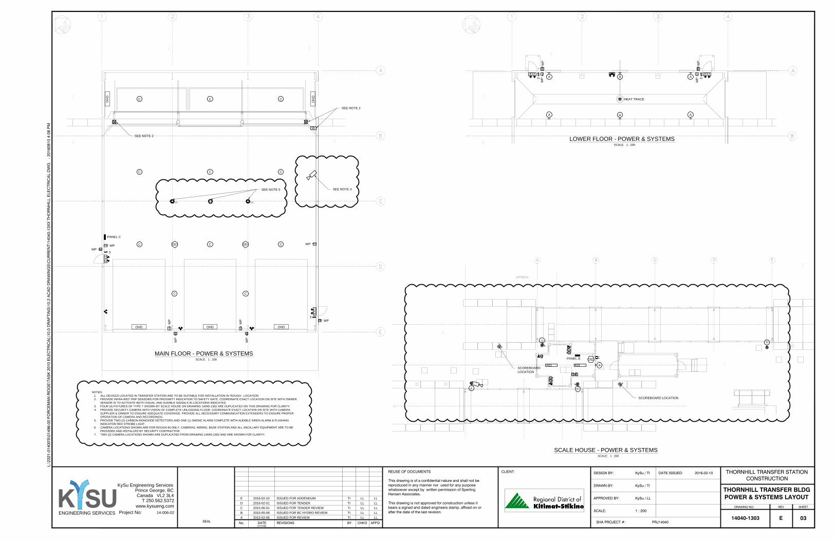
1 : 200
THORNHILL TRANSFER BLDGPOWER & SYSTEMS LAYOUT
0314040-1303ENGINEERING SERVICES
K SU
T 250.562.5372
www.kysueng.com
Canada VL2 3L4
Project No:
Prince George, BC
KySu Engineering Services
14-006-02
BY CHK'D APP'D PRJ14040
KySu / LL
KySu / TI
KySu / TI 2016-02-10
APPROVED BY:
SCALE:
REUSE OF DOCUMENTS DATE ISSUED:
SHA PROJECT #:
DRAWN BY:
DESIGN BY:
SHEETREVDRAWING NO:
REVISIONSSEAL No. DATEyr/m/day
CLIENT: THORNHILL TRANSFER STATIONCONSTRUCTION
E
This drawing is of a confidential nature and shall not bereproduced in any manner nor used for any purposewhatsoever except by written permission of SperlingHansen Associates.
This drawing is not approved for construction unless itbears a signed and dated engineers stamp, affixed on orafter the date of the last revision.
L:\2
321-
0140
0'S
\014
96-0
0 FO
RC
EM
AN
RID
GE
\TA
SK
201
0 E
LEC
TRIC
AL\
10.0
DR
AFT
ING
\10.
2 A
CA
D D
RA
WIN
GS
\CU
RR
EN
T\14
040-
13X
X T
HO
RN
HIL
L E
LEC
TRIC
AL.
DW
G -
201
6081
0 4:
08 P
M
A 2015-02-06 ISSUED FOR REVIEW TI LL LL
B 2015-05-08 ISSUED FOR BC HYDRO REVIEW TI LL LL
C 2015-06-01 ISSUED FOR TENDER REVIEW TI LL LL
D 2016-02-01 ISSUED FOR TENDER TI LL LL
E 2016-02-10 ISSUED FOR ADDENDUM TI LL LL
MAIN FLOOR - POWER & SYSTEMS
SCALE: 1 : 200
LOWER FLOOR - POWER & SYSTEMS
SCALE: 1 : 200
NOTES:
1. ALL DEVICES LOCATED IN TRANSFER STATION ARE TO BE SUITABLE FOR INSTALLATION IN 'ROUGH - LOCATION'
2. PROVIDE INFRA-RED TRIP SENSORS FOR PROXIMITY INDICATION TO SAFETY GATE. COORDINATE EXACT LOCATION ON SITE WITH OWNER.
SENSOR IS TO ACTIVATE BOTH VISUAL AND AUDIBLE SIGNALS IN LOCATIONS INDICATED.
3. FOUR (4) FIXTURES OF TYPE 'I' SHOWN BY SCALE HOUSE ON DRAWING 14040-1302 ARE DUPLICATED ON THIS DRAWING FOR CLARITY.
4. PROVIDE SECURITY CAMERA WITH VISION OF COMPLETE UNLOADING FLOOR. COORDINATE EXACT LOCATION ON SITE WITH CAMERA
SUPPLIER & OWNER TO ENSURE ADEQUATE COVERAGE. PROVIDE ALL NECESSARY COMMUNICATION EXTENDERS TO ENSURE PROPER
OPERATION OF CAMERA AND RECORDINGS.
5. PROVIDE TWO (2) CARBON MONOXIDE DETECTORS AND ONE (1) SMOKE ALARM COMPLETE WITH AUDIBLE SIREN ALARM & FLASHING
INDICATOR RED STROBE LIGHT.
6. CAMERA LOCATIONS SHOWN ARE FOR ROUGH-IN ONLY. CAMERAS, WIRING, BASE STATION AND ALL ANCILLARY EQUIPMENT ARE TO BE
PROVIDED AND INSTALLED BY SECURITY CONTRACTOR.
7. TWO (2) CAMERA LOCATIONS SHOWN ARE DUPLICATED FROM DRAWING 14040-1302 AND ARE SHOWN FOR CLARITY.
C C C
C C
OHD OHD OHD
OH
D
OH
D
EX
1
EX
1
WP
WP
WP
WP
WP
WP
A
EX1 EX1
WP
WP
WP
WP
3
HEAT TRACE
WP
WP
C C C
C C C
A
A
A
AA
3
IR
SEE NOTE 2
SEE NOTE 2
3
3
PANEL C
SCALE HOUSE - POWER & SYSTEMS
SCALE: 1 : 200
I
I
I
I
PANEL B
AF01F01
CO CO
SEE NOTE 4
SCOREBOARD LOCATION
SCOREBOARD
LOCATION
SEE NOTE 5
SS

NTS
THORNHILLELECTRICAL DETAILS
0414040-1304ENGINEERING SERVICES
K SU
T 250.562.5372
www.kysueng.com
Canada VL2 3L4
Project No:
Prince George, BC
KySu Engineering Services
14-006-02
BY CHK'D APP'D PRJ14040
KySu / LL
KySu / TI
KySu / TI 2016-02-10
APPROVED BY:
SCALE:
REUSE OF DOCUMENTS DATE ISSUED:
SHA PROJECT #:
DRAWN BY:
DESIGN BY:
SHEETREVDRAWING NO:
REVISIONSSEAL No. DATEyr/m/day
CLIENT: THORNHILL TRANSFER STATIONCONSTRUCTION
E
This drawing is of a confidential nature and shall not bereproduced in any manner nor used for any purposewhatsoever except by written permission of SperlingHansen Associates.
This drawing is not approved for construction unless itbears a signed and dated engineers stamp, affixed on orafter the date of the last revision.
L:\2
321-
0140
0'S
\014
96-0
0 FO
RC
EM
AN
RID
GE
\TA
SK
201
0 E
LEC
TRIC
AL\
10.0
DR
AFT
ING
\10.
2 A
CA
D D
RA
WIN
GS
\CU
RR
EN
T\14
040-
13X
X T
HO
RN
HIL
L E
LEC
TRIC
AL.
DW
G -
201
6081
0 4:
08 P
M
A 2015-02-06 ISSUED FOR REVIEW TI LL LL
B 2015-05-08 ISSUED FOR BC HYDRO REVIEW TI LL LL
C 2015-06-01 ISSUED FOR TENDER REVIEW TI LL LL
D 2016-02-01 ISSUED FOR TENDER TI LL LL
E 2016-02-10 ISSUED FOR ADDENDUM TI LL LL
TYPICAL TRENCH DETAIL
SCALE: NTS
GRADE
POWER CONDUIT
QUANTITY AS REQUIRED
SAND BEDDING
NATIVE FILL
WARNING TAPE
COMMUNICATIONS CONDUIT
QUANTITY AS REQUIRED
1' (300mm)
MIN
6" (150mm) MIN
3' (900mm)
MIN COVER
6" (1
50
mm
) M
IN
CONDUIT
FINISHED GRADE
TWO PIECE COVER
HAND HOLE
ALL POLES, DECORATIVE
BASES, DISTRIBUTION BASES
AND NUT COVERS ARE TO BE
GALVANIZED.
TAPERED SQUARE POLE OR
STRAIGHT SQUARE POLE
LUMINAIRE OF TYPE 'G', 'H' OR 'I'
REFER TO LUMINAIRE SCHEDULE
FOR DETAILS
CONCRETE BASE
EXTERIOR LIGHT FIXTURE
MOUNTING DETAIL
SCALE: NTS
EXTERIOR LIGHTING CONCRETE PEDESTAL
SCALE: NTS
FOUR (4) ANCHOR BOLTS TO
SUIT POLE BASE
EIGHT (8) 20M VERTS.
10M TIES @ 8" O.C.
1.25" (32mm) CHAMFER
FOUR (4) ANCHOR BOLTS TO
SUIT POLE BASE
ELECTRICAL CONDUIT
EIGHT (8) 20M VERTS.
10M TIES @ 8" O.C.
ASPHALT PAVING
1" (25mm) RPVC - QUANTITY &
LAYOUT AS REQUIRED
3' (900mm)
6' (1800mm)
3" (75mm)3" (75mm)
3" (75mm)
22" (560mm)
30' (9.1m)
3' (900mm)
ELECTRICAL SERVICE KIOSK
SCALE: NTS
INCOMING BC HYDRO FEED
SEE KIOSK NOTES 5 & 6
PA
NE
L A
BC HYDRO METER
FUSED SWITCH
TRANSFER SWITCH
FLUORESCENT STRIP
500W BASEBOARD
WITH INTEGRAL
THERMOSTAT
KIOSK NOTES:
1. EXACT KIOSK LAYOUT MAY BE ADJUSTED TO SUIT EQUIPMENT LAYOUT.
2. KIOSK IS TO BE SIZED TO SUIT ALL SHOWN EQUIPMENT AND ANY ANCILLARY EQUIPMENT REQUIRED.
3. PROVIDE DIMENSIONED LAYOUT DRAWING FOR KIOSK PRIOR TO ORDERING ANY EQUIPMENT.
4. ALL INCOMING AND OUTGOING CONDUITS ARE TO BE 36" (900mm) BELOW GRADE AT ALL POINTS.
5. BOTTOM OF KIOSK DOORS ARE TO BE MINIMUM 300mm (12") ABOVE FINISHED GRADE.
6. PROVIDE CONCRETE BASE FOR KIOSK AS PER KIOSK MANUFACTURERS REQUIREMENTS. CONCRETE
BASE IS TO BE 50mm (2") LARGER IN EACH DIRECTION THAN THE KIOSK.
7. PROVIDE GENERATOR JUNCTION BOX WITH HARDWIRED TERMINAL STRIPS FOR FUTURE GENERATOR.
JUNCTION BOX AND TERMINAL STRIPS ARE TO BE RATED FOR 200A @ 240V.
GENERATOR JUNCTION BOX
SEE KIOSK NOTE 7
TV
SS
FIXTURE NOTES:
1. FOR LOCATIONS WITH A POLE MOUNTED CAMERA, POLE IS TO BE A 35' (10.7m) POLE.
2. FOR LOCATIONS WITHOUT A CAMERA, POLE IS TO BE A 30' (9.1m) POLE.
3. CAMERA IS TO BE MOUNTED A MINIMUM OF 40" (1m) ABOVE FIXTURES.
35' (10.7m)
ENTRANCE/EXIT GATE
CARD READER POST DETAIL
SCALE: NTS
2' (610mm)
MINIMUM
2' (610mm)
CONDUIT COUPLING
1' (305mm) DIA FOOTING
2" (50mm) DB2
TO JUNCTION BOX
CARD READER
FINAL HEIGHT
TO BE COORDINATED
ON SITE
RED/GREEN TRAFFIC LIGHT & LED DISPLAY
SCOREBOARD DETAIL
SCALE: NTS
2m (6.5')
100mm (4")
SCALE DECK
SCOREBOARD & TRAFFIC
LIGHT ASSEMBLY
SEE NOTE 2
SCOREBOARD
RED/GREEN LIGHT
PROVIDE CLAMPING AND/OR
SUPPORTS AS REQUIRED
SEE NOTE 1
SCOREBOARD NOTES:
1. PROVIDE TWO (2) 25mm RPVC CONDUITS.
1.1. ONE (1) 25mm CONDUIT FOR POWER.
1.1.1. COORDINATE WITH SCOREBOARD SUPPLIER FOR EXACT POWER
REQUIREMENTS AND INTERCONNECTION METHOD.
1.2. ONE (1) 25mm CONDUIT FOR COMM.
1.2.1. COMM CONDUIT TO BE COMPLETE WITH TWO (2) CAT5e CABLES TERMINATED
WITH RJ45 JACKS. COORDINATE WITH SCOREBOARD SUPPLIER FOR EXACT
TERMINATION METHOD AND LOCATION INSIDE SCALE HOUSE.
1.3. CONDUIT ROUTING TO SUIT SITE CONDITIONS.
2. PROVISION OF SCOREBOARD & TRAFFIC LIGHT ASSEMBLY IS THE RESPONSIBILITY OF
THE GENERAL CONTRACTOR. DIVISION 26 TO ASSIST WITH INSTALL &
COMMISSIONING.

NTS
THORNHILLELECTRICAL SPECIFICATIONS
0514040-1305ENGINEERING SERVICES
K SU
T 250.562.5372
www.kysueng.com
Canada VL2 3L4
Project No:
Prince George, BC
KySu Engineering Services
14-006-02
BY CHK'D APP'D PRJ14040
KySu / LL
KySu / TI
KySu / TI 2016-02-10
APPROVED BY:
SCALE:
REUSE OF DOCUMENTS DATE ISSUED:
SHA PROJECT #:
DRAWN BY:
DESIGN BY:
SHEETREVDRAWING NO:
REVISIONSSEAL No. DATEyr/m/day
CLIENT: THORNHILL TRANSFER STATIONCONSTRUCTION
E
This drawing is of a confidential nature and shall not bereproduced in any manner nor used for any purposewhatsoever except by written permission of SperlingHansen Associates.
This drawing is not approved for construction unless itbears a signed and dated engineers stamp, affixed on orafter the date of the last revision.
L:\2
321-
0140
0'S
\014
96-0
0 FO
RC
EM
AN
RID
GE
\TA
SK
201
0 E
LEC
TRIC
AL\
10.0
DR
AFT
ING
\10.
2 A
CA
D D
RA
WIN
GS
\CU
RR
EN
T\14
040-
13X
X T
HO
RN
HIL
L E
LEC
TRIC
AL.
DW
G -
201
6081
0 4:
08 P
M
A 2015-02-06 ISSUED FOR REVIEW TI LL LL
B 2015-05-08 ISSUED FOR BC HYDRO REVIEW TI LL LL
C 2015-06-01 ISSUED FOR TENDER REVIEW TI LL LL
D 2016-02-01 ISSUED FOR TENDER TI LL LL
E 2016-02-10 ISSUED FOR ADDENDUM TI LL LL
1. SCOPE OF WORK
1.1. PROVIDE ALL NECESSARY LABOUR, MATERIAL, TOOLS, TRANSPORTATION, SERVICES AND
FACILITIES REQUIRED FOR THE COMPLETE ELECTRICAL INSTALLATION AS SHOWN ON THE
DRAWINGS AND AS SPECIFIED.
1.2. PROVIDE ALL NECESSARY LABOUR, MATERIALS, EQUIPMENT, DEVICES AND APPARATUS
NOT MENTIONED IN THE SPECIFICATIONS, OR SHOWN ON THE DRAWINGS AS REQUIRED
FOR THE COMPLETE ELECTRICAL INSTALLATION.
2. CODE, RULES AND REGULATIONS
2.1. ELECTRICAL INSTALLATION SHALL BE IN ACCORDANCE WITH THE CURRENT EDITION OF
THE CANADIAN ELECTRICAL CODE, NATIONAL BUILDING CODE, AND APPLICABLE
MUNICIPAL AND PROVINCIAL CODES, RULES AND REGULATIONS.
2.2. PROVIDE ALL NECESSARY MATERIAL AND LABOUR REQUIRED TO MEET THE
REQUIREMENTS OF THESE CODES, RULES AND REGULATIONS EVEN THOUGH THE WORK
MAY NOT BE SHOWN ON THE DRAWINGS OR MENTIONED IN THE SPECIFICATIONS.
3. PERMITS AND FEES
3.1. OBTAIN ALL PERMITS AND PAY ALL FEES REQUIRED FOR THE ELECTRICAL INSTALLATION.
4. CO-OPERATION WITH OTHER TRADES
4.1. CHECK WITH OTHER TRADES TO AVOID DELAYS.
5. APPROVAL OF MATERIALS
5.1. ELECTRICAL EQUIPMENT SHALL BE NEW AND OF THE TYPE AND QUALITY SPECIFIED.
6. CERTIFICATION OF INSPECTION
6.1. OBTAIN A CERTIFICATE OF INSPECTION AND APPROVAL FROM THE ELECTRICAL
INSPECTION DEPARTMENT HAVING JURISDICTION OVER THE WORK. CERTIFICATE OF
INSPECTION SHALL BE SUBMITTED TO THE ARCHITECT ON COMPLETION OF THE WORK.
7. CLEAN UP
7.1. REMOVE ALL DEBRIS FROM THE SITE AS IT OCCURS, AND DO NOT ALLOW TO
ACCUMULATE.
7.2. TOUCH UP WITH MATCHING PAINT ANY EQUIPMENT THAT HAS BEEN DAMAGED DURING
CONSTRUCTION.
8. GUARANTEE
8.1. THE SATISFACTORY OPERATION OF ALL WORK AND APPARATUS INCLUDED AND
INSTALLED UNDER THIS SECTION OF THE SPECIFICATION SHALL BE GUARANTEED
8.2. REPLACE FORTHWITH, AT NO ADDITIONAL COST TO THE OWNER, ANY PART WHICH MAY
PROVE TO BE DEFECTIVE WITHIN A PERIOD OF TWELVE MONTHS AFTER THE FINAL
ACCEPTANCE OF THE COMPLETE BUILDING, PROVIDED THAT SUCH FAILURE IS NOT DUE
TO ANY IMPROPER USAGE OR ORDINARY WEAR AND TEAR
8.3. NO CERTIFICATE GIVEN, PAYMENT MADE, PARTIAL OR ENTIRE USE OF THE EQUIPMENT BY
THE OWNER, SHALL BE CONSTRUED AS ACCEPTANCE OF DEFECTIVE WORK.
9. EARTH QUAKE RESISTANTS
9.1. PROVIDE SEISMIC RESISTANT AND ANCHORAGE FOR ALL LIGHTING FIXTURES TO COMPLY
WITH THE LOCAL BUILDING BYLAWS
9.2. THIS CONTRACTOR SHALL ENGAGE A SEISMIC RESTRAINT CONSULTANT TO DESIGN AND
REVIEW SEISMIC RESTRAINTS FOR ALL WORK ASSOCIATED WITH DIVISION 16. THE SEISMIC
RESTRAINT CONSULTANT SHALL SUPERVISE THEIR INSTALLATION AND SUBMIT THE
REQUISITE ASSURANCES TO THE LOCAL MUNICIPAL AUTHORITIES
9.3. SUBMIT ASSURANCE COMMITMENT LETTER FROM THE SEISMIC RESTRAINT CONSULTANT
AT THE COMMENCEMENT OF THE PROJECT AND ITS COMPLETION
9.4. ALL RECESSED LIGHTING FIXTURES IN MECHANICAL GRID CEILINGS (T- BAR) SHALL BE
RESTRAINED USING AT LEAST TWO (2) (ONE FOR INCA NDESCENT FIXTURES) #16 AW G
STRANDED STAINLESS STEEL AIRCRAFT CABLE SECURITY BRIDLES PER FIXTURE TIED TO
THE BASIC BUILDING STRUCTURE. ATTACH EACH SECURITY CABLES AT ENDS OF EACH
FIXTURE USING A FURTHER ATTACHMENT TO EACH CORNER OF THE FIXTURE AND IN
SUCH A MANNER THAT THE FIXTURE CANNOT FALL LOWER THAN 300MM BENEATH FIXTURE
INSTALLED HEIGHT
10. CONDUIT AND RACEWAY
10.1. RIGID STEEL CONDUIT: FOR ALL EXPOSED AND UNDERGROUND CONDUIT EXPOSED TO
MECHANICAL DAMAGE. (MINIMUM SIZE: 3/4")
10.2. ELECTRICAL METALLIC TUBING (EMT): INTERIOR POWER AND LIGHTING BRANCH CIRCUITS
WHERE RUN CONCEALED ABOVE SUSPENDED CEILING, IN STUD WALLS, FURRED SPACES,
AND WHERE NOT EXPOSED TO MECHANICAL DAMAGE, OR ABOVE 6' FROM FLOOR.
10.3. ELECTRICAL NON-METALLIC TUBING (ENT): INTERIOR BRANCH CIRCUITS &
COMMUNICATIONS CABLING WHERE ENCLOSED IN CONCRETE SLAB. ENT MUST BE
SMOOTH INTERIOR WALL TYPE. SUBMIT SHOP DRAWING FOR APPROVAL PRIOR TO USE.
(MINIMUM SIZE: 3/4")
10.4. FLEXIBLE METALLIC CONDUIT: IN DRY LOCATIONS, CONNECTION TO TRANSFORMERS, (6'
MAX.), VIBRATING EQUIPMENT (24" MAX) AND TO RECESSED LIGHTING FIXTURES
10.5. LIQUID-TIGHT FLEXIBLE METALLIC CONDUIT: IN DAMP AND WET LOCATIONS FOR
CONNECTION TO ALL PUMP MOTORS, SOLENOID VALVES, HVAC EQUIPMENT AND SIMILAR
DEVICES SHALL BE MADE USING LIQUID TIGHT FLEXIBLE METALLIC CONDUIT. PROVIDE
SEPARATE GROUND WIRE INDEPENDENT OF CONDUIT, RUN INSIDE CONDUIT AND BONDED
AT BOTH ENDS TO ENCLOSURES. MAXIMUM LENGTH OF 24 INCHES.
10.6. CONDUIT IN DIRECT CONTACT WITH EARTH TO BE RIGID PVC TYPE.
10.7. CONDUIT SYSTEM SHALL BE CONCEALED UNLESS EXPOSED WORK IS CLEARLY CALLED
FOR ON DRAWINGS
10.8. CONDUITS SHALL BE TIGHTLY COVERED AND WELL PROTECTED DURING CONSTRUCTION
USING METALLIC BUSHINGS AND BUSHING "PENNIES" TO SEAL OPEN END
10.9. IN ALL EMPTY CONDUITS OR DUCTS, INSTALL A 200-POUND TENSILE STRENGTH
POLYETHYLENE PULLING ROPE
10.10. CONDUIT SYSTEMS SHALL BE ELECTRICALLY CONTINUOUS THROUGHOUT. INSTALL CODE
SIZED, INSULATED, COPPER, GREEN GROUNDING CONDUCTOR IN ALL CONDUIT RUNS
PULLED WITH PHASE AND NEUTRAL CONDUCTORS
10.11. LOCATIONS OF CONDUIT RUNS SHALL BE PLANNED IN ADVANCE OF THE INSTALLATION
AND COORDINATED WITH THE DUCTWORK, PLUMBING, CEILING AND WALL CONSTRUCTION
IN THE SAME AREAS AND SHALL NOT UNNECESSARILY CROSS OTHER CONDUITS OR PIPE,
NOR PREVENT REMOVAL OF CEILING OR TILES OR PANELS, NOR BLOCK ACCESS TO
MECHANICAL OR ELECTRICAL EQUIPMENT
10.12. WHERE PRACTICAL, INSTALL CONDUITS IN GROUPS, IN PARALLEL, FOR VERTICAL AND
HORIZONTAL RUNS AND AT ELEVATIONS THAT AVOID UNNECESSARY OFFSETS
10.13. EXPOSED CONDUIT SHALL BE RUN PARALLEL OR AT RIGHT ANGLES TO THE CENTERLINES
OF COLUMNS AND BEAMS
10.14. CONDUITS SHALL NOT BE PLACED CLOSER THAN 12 INCHES FROM A PARALLEL HOT
WATER OR STEAM LINE OR 3 INCHES FROM SUCH LINES CROSSING PERPENDICULAR TO
THE RUNS
10.15. ALL RACEWAY SYSTEMS SHALL BE SECURED TO THE BUILDING STRUCTURES USING
SPECIFIED FASTENERS, CLAMPS AND HANGERS SPACED ACCORDING TO CODE
REQUIREMENTS
10.16. SUPPORT SINGLE RUNS OF CONDUIT USING ONE HOLE PIPE STRAPS. WHERE RUN
HORIZONTALLY ON WALLS IN DAMP OR WET LOCATION, INSTALL "CLAMP-BACKS" TO SPACE
CONDUIT OFF THE SURFACE
10.17. MULTIPLE CONDUIT RUNS SHALL BE SUPPORTED USING "TRAPEZE" HANGERS,
FABRICATED FROM SPECIFIED CONSTRUCTION CHANNEL, MOUNTED TO 3/8 INCH
DIAMETER, THREADED STEEL RODS SECURED TO BUILDING STRUCTURES. FASTEN
CONDUIT TO CONSTRUCTING CHANNEL WITH STANDARD ONE HOLE PIPE CLAMPS OR THE
EQUIVALENT
10.18. RACEWAYS SHALL BE JOINED USING SPECIFIED COUPLING OR TRANSITION COUPLINGS
WHERE DISSIMILAR RACEWAY SYSTEMS ARE JOINED.
10.19. CONDUITS SHALL BE SECURELY FASTENED TO CABINETS, BOXES, AND GUTTERS USING
TWO LOCKNUTS AND AN INSULATING BUSHING OR SPECIFIED INSULATING CONNECTORS.
INSTALL GROUNDING BUSHINGS OR BONDING JUMPERS ON ALL CONDUITS TERMINATING
AT CONCENTRIC KNOCKOUTS.
10.20. CONDUIT TERMINATIONS EXPOSED AT WEATHERPROOF ENCLOSURES AND CAST OUTLET
BOXES SHALL BE MADE WATERTIGHT USING SPECIFIED CONNECTORS AND HUBS.
10.21. INSTALL EXPANSION COUPLINGS WHERE ANY CONDUIT CROSSES A BUILDING SEPARATION
OR EXPANSION JOINT.
10.22. ALL FLOOR PENETRATIONS SHALL BE SEALED WATER-TIGHT. MAINTAIN FIRE RATING AS
REQUIRED.
10.23. FIRE-SAFE ALL RATED WALL PENETRATIONS USING 3M LISTED FIRE-SAFING SEALANTS
AND ASSEMBLIES.
11. BOXES AND WIRING SERVICES
11.1. ALL OUTLETS SHALL FINISH FLUSH WITH BUILDING WALLS AND CEILING, EXCEPT WHERE
EXPOSED WORK IS CALLED FOR. THERE SHALL BE NO GAP BETWEEN BOX AND WALL OR
CEILING MATERIAL. ANY OPENING BETWEEN BOX AND WALL OR CEILING SHALL BE
CAULKED AIRTIGHT.
11.2. INSTALL RAISED DEVICE COVERS ON ALL OUTLET BOXES AS REQUIRED TO FINISH FLUSH
WITH SURFACE. COVERS SHALL BE OF A DEPTH TO SUIT THE WALL OR CEILING FINISH.
11.3. EXPOSED OUTLET BOXES AND BOXES IN DAMP AND WET LOCATIONS SHALL BE CAST
METAL WITH GASKETED CAST METAL COVER PLATES.
11.4. OUTLET BOXES SHALL BE INSTALLED AT THE LOCATIONS AND ELEVATIONS SHOWN ON
THE DRAWINGS OR SPECIFIED HEREIN. MAKE ADJUSTMENTS TO LOCATIONS AS REQUIRED
BY STRUCTURAL CONDITIONS AND TO SUIT COORDINATION REQUIREMENTS OF OTHER
TRADES.
11.5. OUTLET BOXES IN STUD WALL AND PARTITIONS SHALL NOT BE MOUNTED BACK-TO-BACK
NOR SHALL THROUGH-WALL BOXES BE PERMITTED.
11.6. BOXES INSTALLED IN STUD WALLS SHALL BE EQUIPPED WITH BRACKETS DESIGNED FOR
ATTACHING DIRECTLY TO THE STUDS OR SHALL BE MOUNTED ON HEAVY GAUGE
GALVANIZED STEEL BOX SUPPORTS.
11.7. FIXTURE OUTLET BOXES INSTALLED IN SUSPENDED CEILINGS OF GYPSUM BOARD OR LATH
AND PLASTER CONSTRUCTION SHALL BE MOUNTED TO 16 GAUGE METAL CHANNEL BARS
ATTACHED TO MAIN CEILING RUNNERS.
11.8. FIXTURE OUTLET BOXES INSTALLED IN SUSPENDED CEILINGS SYSTEMS SUPPORTING
ACOUSTICAL TILES OR PANELS SHALL BE SUPPORTED DIRECTLY FROM THE STRUCTURES
ABOVE WHEREVER PENDANT MOUNTED FIXTURES ARE INSTALLED FROM THE BOX.
11.9. MOUNTING HEIGHTS: MOUNTING HEIGHTS FROM FINISHED FLOOR TO CENTER LINE OF
DEVICE BOX SHALL BE AS FOLLOWS, AND IN ACCORDANCE WITH HANDICAPPED
ACCESSIBILITY REQUIREMENTS OF GOVERNING CODE.
11.9.1. CONVENIENCE RECEPTACLE - 18" (450MM)
11.9.2. CONVENIENCE RECEPTACLE ABOVE COUNTER - 42" 1060MM)
11.9.3. LIGHT SWITCHES - 48" (1220MM)
11.9.4. TELEPHONE OUTLET - 18" (450MM)
11.9.5. FIRE ALARM STATIONS - 55" 1397MM)
11.9.6. FIRE ALARM BELLS - 12" BELOW CEILING AND NO MORE THAN 110"
11.9.7. EMERGENCY LIGHT HEADS - 90" (2300MM)
12. CABLE AND WIRE
12.1. CONDUCTORS SHALL NOT BE INSTALLED IN CONDUIT UNTIL ALL WORK OF ANY NATURE
THAT MAY CAUSE DAMAGE IS COMPLETED. CARE SHALL BE TAKEN IN PULLING
CONDUCTORS THAT INSULATION IS NOT DAMAGED. U.L. AND C.S.A. APPROVED
NON-PETROLEUM BASE AND INSULATING TYPE PULLING COMPOUND SHALL BE USED AS
NEEDED.
12.2. ALL CABLES SHALL BE INSTALLED AND TESTED IN ACCORDANCE WITH MANUFACTURERS
REQUIREMENTS AND WARRANTY.
12.3. ALL ASPECTS OF SPLICING AND TERMINATING SHALL BE IN ACCORDANCE WITH CABLE
MANUFACTURERS PUBLISHED PROCEDURES.
12.4. MAKE UP ALL SPLICES IN OUTLET BOXES WITH CONNECTORS AS SPECIFIED HEREIN WITH
SEPARATE TAILS OF CORRECT COLOR TO BE MADE UP TO SPLICE. PROVIDE AT LEAST SIX
(6) INCHES OF TAILS PACKED IN BOX AFTER SPLICE IS MADE UP.
12.5. ALL WIRE AND CABLE IN PANELS, TERMINAL CABINETS AND EQUIPMENT ENCLOSURES
SHALL BE BUNDLED AND CLAMPED.
12.6. MINIMUM WIRE SIZE SHALL BE NO. 12 AWG R90 COPPER.
13. WIRING DEVICES
13.1. SWITCHES
13.1.1. SPECIFICATION GRADE, WHITE , DECORATOR STYLE AVAILABLE FOR BACK AND SIDE
WIRING. 20A, 120V OR 347V, SINGLE POLE, DOUBLE POLE, THREE-WAY OR FOUR-WAY
AS INDICATED.
13.2. RECEPTACLES
13.2.1. SPECIFICATION GRADE, WHIT E, DECORATOR STYLE DUPLEX RECEPTACLE CSA TYPE
5-15R, 125V, 15A U-GROUNDED.
13.2.2. INSTALL ALL RECEPTACLES IN THE VERTICAL PLANE UNLESS OTHERWISE NOTED.
13.3. DIMMERS
13.3.1. FLUSH MOUNTED TYPE, WHITE. (1000 WATTS RATED)
13.3.2. ELECTRONIC WITH PRESET.
13.4. COVER PLATES
13.4.1. STAINLESS STEEL, 1mm THICK BRUSHED COVER PLATES.
13.4.2. WEATHERPROOF, DURABLE, 'IN-USE' RATED COVER PLATES COMPLETE WITH
GASKETS FOR WP DUPLEX RECEPTACLES AS INDICATED.
13.4.3. INSTALL SINGLE THROW SWITCHES WITH HANDLE IN "UP" POSITION WHEN SWITCH
CLOSED.
13.4.4. INSTALL RECEPTACLES/SWITCHES VERTICALLY IN GANG TYPE OUTLET BOX WHEN
MORE THAN ONE RECEPTACLE IS REQUIRED IN ONE LOCATION.
14. PANEL BOARDS
14.1. RATINGS: REFER TO PANEL SCHEDULES SHOWN ON DRAWING.
14.2. FINISH: ALL PAINTED STEEL WORK SHALL BE TREATED WITH A PRIMER COAT AND FINISH
COAT OF THE MANUFACTURER'S STANDARD GRAY COLOR OR ANSI 61.
14.3. PANEL BOARDS TO HAVE FLUSH DOORS WITH TWO KEYS FOR EACH PANEL BOARD (ALL
KEYS TO BE ALIKE).
14.4. BUSSING
14.4.1. BUSSING SHALL BE RECTANGULAR CROSS SECTION FULL LENGTH TIN PLATED
ALUMINUM.
14.4.2. EACH PANEL BOARD SHALL BE EQUIPPED WITH A GROUND BUS SECURED TO THE
INTERIOR OF THE ENCLOSURE. THE BUS SHALL BE EQUAL TO THE PANEL BOARD
NEUTRAL BUS AND SHALL HAVE A SEPARATE LUG FOR EACH GROUND CONDUCTOR.
NOT MORE THAN ONE CONDUCTOR SHALL BE INSTALLED PER LUG.
14.4.3. PANEL BOARD DIRECTORIES: SHALL BE TYPEWRITTEN, ARRANGE IN NUMERICAL
ORDER AND SHALL SHOW THE NUMBER OF THE CIRCUIT IS INDICATED. THE ROOM
NUMBERS SHALL BE VERIFIED WITH THE OWNER AND SHALL NOT NECESSARILY BE
THOSE USED IN THE DRAWINGS. MOUNT DIRECTORIES INSIDE EACH PANEL BOARD.
14.4.4. ACCEPTABLE MANUFACTURERS: SIEMENS, CUTLER HAMMER, SCHNEIDER CANADA.
15. PROTECTIVE DEVICES
15.1. CIRCUIT BREAKERS: MOLDED CASE, BOLT-ON, THERMAL MAGNETIC TYPE, 40 DEGREES C.
AMBIENT TEMPERATURE COMPENSATED, FIXED MOUNTING, WITH QUICK-MAKE AND
QUICK-BREAK SWITCHING MECHANISM MECHANICALLY TRIP-FREE FROM THE OPERATING
HANDLE.
15.2. RATINGS: REFER TO DRAWINGS AND PANEL SCHEDULES FOR TRIP FRAME AND POLES
REQUIRED. MINIMUM SHORT CIRCUIT RATING FOR 120/240 VOLT BREAKERS IS 10,000 A, IF
NOT INDICATED OTHERWISE.
15.3. MANUAL MOTOR STARTERS: FRACTIONAL H.P. 1 PHASE MOTORS SHALL BE PROTECTED BY
THERMAL O.L. RELAY INTEGRAL WITH THE DISCONNECT.
16. GROUNDING
16.1. ENCLOSURES OF EQUIPMENT, RACEWAYS, AND FIXTURES SHALL BE PERMANENTLY AND
EFFECTIVELY GROUNDED. PROVIDE CODE-SIZED (UNLESS OTHERWISE INDICATED)
COPPER, INSULATED GREEN EQUIPMENT GROUND WITH ALL BRANCH AND FEEDER
CIRCUIT RUNS. EQUIPMENT GROUND SHALL ORIGINATE AT PANEL BOARD GROUND BUS
AND SHALL BE BONDED TO ALL SWITCH AND RECEPTACLE BOXES AND ELECTRICAL
EQUIPMENT ENCLOSURES.
16.2. BUILDING SERVICES SHALL BE GROUNDED TO BUILDING STEEL, TO COLD METALLIC
WATER PIPING, AND GROUND RODS (3/4" X 10 FT COPPER).
17. TRANSFORMERS
17.1. TRANSFORMERS SHALL BE INDOOR TYPE, SELF COOLED SINGLE OR THREE-PHASE DUAL
WINDING, FULLY ENCLOSED, VENTILATED, GENERAL PURPOSE DRY TYPE, 600 VOLT
PRIMARY, 347/600 VOLT OR 120/208 VOLT SECONDARY AS INDICATED, 60 HERTZ, EQUIPPED
WITH FOUR 2.5% VOLTAGE TAPS ABOVE AND BELOW RATED VOLTAGE AND SHALL BE OF
THE KVA RATING SHOWN ON THE DRAWINGS.
17.2. TRANSFORMERS SHALL HAVE COPPER OR ALUMINUM WINDINGS CLASS `H' INSULATION
GROUP, WITH TEMPERATURE RISE, WHEN OPERATED CONTINUOUSLY AT FULL LOAD AND
RATED FREQUENCY, NOT EXCEEDING 150 DEGREE C. RISE OVER 40 DEGREE C. AMBIENT,
UNLESS MENTIONED OTHERWISE ON THE ONE-LINE DIAGRAM.
17.3. TRANSFORMERS SHALL HAVE A MINIMUM OF 10% OVERLOAD CAPACITY AT RATED
VOLTAGE AND SHALL HAVE A 10 KV BILL RATING.
17.4. SOUND LEVEL AT ANY LOAD SHALL NOT EXCEED 45DB WHEN TESTED IN A ROOM WITH
AMBIENT SOUND LEVEL NOT EXCEEDING 24 DB. EXCESSIVELY NOISY TRANSFORMERS
SHALL BE REPLACED.
17.5. TRANSFORMER IMPEDANCE SHALL NOT BE LESS THAN NOR GREATER THAN 5%.
TRANSFORMER HALL CONFORMS TO NEMA TRI-1974, CEC 450-21 AND ALL APPLICABLE
PROVINCIAL AND LOCAL CODES.
17.6. TRANSFORMER SHALL NOT CONTAIN ANY PCB'S (POLYCHLORINATED BIPHENYLS)
17.7. TRANSFORMER SIZE SHALL FIT SPACE ALLOCATED PER DRAWINGS.
17.8. TRANSFORMER SHALL BE FLOOR/WALL MOUNTED AS SHOWN ON THE DRAWINGS AND AS
DIRECTED BY THE ENGINEER. FURNISH AND INSTALL ALL MOUNTING HARDWARE TO
SAFELY CARRY THE WEIGHT OF THE TRANSFORMER. MAINTAIN ADEQUATE SPACING FOR
VENTILATION AS RECOMMENDED BY THE MANUFACTURER AND REQUIRED BY CODE.
17.9. PROVIDE NEOPRENE TYPE VIBRATION INSULATION PADS FOR EACH TRANSFORMER.
VIBRATION AND SEISMIC CONTROL SHALL MEET NBC AND SUPPLEMENTS REQUIREMENT.
17.10. CONNECTIONS TO TRANSFORMERS SHALL BE MADE WITH FLEXIBLE METALLIC CONDUIT.
INSTALL GROUND CONDUCTORS IN EACH CONDUIT AND PROVIDE GROUNDING BUSHINGS
AS REQUIRED.
17.11. PROVIDE "WONDER BOARD" HEAT INSULATING BARRIER AROUND TRANSFORMER WHERE
INSTALLED ON COMBUSTIBLE SURFACE.
17.12. ACCEPTABLE MANUFACTURERS: SIEMENS, SCHNEIDER, POLYGON, CUTLER HAMMER,
MARCUS, DELTA, HAMMOND, AND REX.
18. LIGHTING FIXTURES
18.1. SUBMIT SHOP DRAWINGS PRIOR TO ORDERING.
18.2. ALL FIXTURES ARE TO BE AS PER LUMINAIRE SCHEDULE.
18.3. LED SCREW-IN LAMPS:
18.3.1. LED SCREW IN LAMPS SHALL BE 4000 DEGREE K UNLESS SPECIFIED OTHERWISE.
18.3.2. LUMEN OUTPUTS SHALL BE AS PER LUMINAIRE SCHEDULES. MINIMUM LUMENS PER
WATT FOR ALL LED SCREW-IN LAMPS SHALL BE MINIMUM 70 LPW.
18.3.3. SUBMIT SHOP DRAWINGS PRIOR TO ORDERING.
18.4. FLUORESCENT LAMPS:
18.4.1. ALL FLUORESCENT LAMPS SHALL BE 32W, 2950 LUMEN, T-8 ENERGY SAVING, 4000
DEGREE K (CRI-85) , LONG LIFE (36,000 HR) UNLESS SPECIFIED OTHERWISE
18.4.2. LAMPS SHALL BE AS MANUFACTURED BY G.E, OSRAM, VENTURE, SYLVANIA.
18.5. FLUORESCENT LAMP BALLASTS :
18.5.1. BALLAST'S FOR ALL TUBE FLUORESCENT LAMPS SHALL BE U.L. APPROVED, CBM
CERTIFIED OR ETL TESTED, CLASS P, SOUND RATED A, ENERGY-SAVING, ELECTRONIC
PROGRAM START.
18.5.2. BALLASTS SHALL BE APPROVED FOR USE WITH ENERGY SAVING LAMPS BY THE LAMP
MANUFACTURER.
19. INSTALLATION
19.1. CONTRACTOR SHALL BE RESPONSIBLE FOR HANDLING AND STORAGE. FIXTURE S SHALL BE
INSTALLED PLUMB, LEVEL, IN STRAIGHT LINES WITHOUT DISTORTION AND CLEAN.
19.2. INSTALL EACH FIXTURE IN A MANNER RECOMMENDED BY THE FIXTURE MANUFACTURER
AND APPROVED BY THE OWNER'S REPRESENTATIVE. UNDER THIS SECTION OF THE WORK,
FURNISH AND INSTALL ALL ADDITIONAL CEILING BRACING, HANGER SUPPORTS AND
OTHER STRUCTURAL REINFORCEMENTS TO THE BUILDING REQUIRED TO PROPERLY AND
SAFELY SUSPEND FIXTURES, ALL AS APPROVED BY THE ENGINEER.
19.3. FIXTURES IN AREAS OF EXPOSED DUCT AND PIPE WORK SHALL BE SUSPENDED TO AVOID
CONFLICT WITH SAME.
19.4. PENDANT FIXTURES SHALL BE PROVIDED WITH BALL ALIGNERS AND SWAY ADAPTERS.
FIXTURE CHAIN SHALL NOT BE USED FOR SUPPORTING FIXTURE S.
19.5. PROVIDE SEISMIC WIRE SUPPORTS FOR EACH SUSPENDED FIXTURE, SECURED TO THE
BUILDING STRUCTURE INDEPENDENT OF THE CEILING SUPPORTING SYSTEM.
20. IDENTIFICATION
20.1. IDENTIFY ALL PLACES OF ELECTRICAL EQUIPMENT (INCLUDING EACH AND EVERY
RECEPTACLE) OTHER THAN CONDUITS AND CONDUCTORS WITH ENGRAVED LAMINATED
PLASTIC NAMEPLATES OR BROTHER P-TOUCH LABELS HAVING 3MM MINIMUM HEIGHT.
BLACK CHARACTERS ON WHITE BACKGROUND FOR NORMAL POWER. ATTACH ALL
LAMACOID LABELS, UNLESS OTHERWISE DIRECTED WITH SILICONE CEMENT.
20.2. ALL JUNCTION AND PULLBOXES FOR CONDUITS, DUCTS AND OTHER RACEWAYS IN
CONCEALED CEILING SPACES SHALL BE PERMANENTLY MARKED USING A BLACK FELT PEN
AS FOLLOWS. (WHERE CEILING SPACE IS PAINTED OUT, PUT MARKING ON INSIDE OF
COVERPLATES).
20.3. FOR LIGHTING AND POWER SHOW THE COMPLETE CIRCUIT NUMBER OF ALL ENCLOSED
CIRCUITS. FOR ALL COMMUNICATIONS AND FIRE ALARM SHOW THE USAGE (IE. "FIRE
ALARM", "TELEPHONE")
21. EXIT SIGNS
21.1. SUBMIT SHOP DRAWINGS PRIOR TO ORDERING.
21.2. ALL EXIT SIGNS SHALL CONFORM TO CURRENT CSA 'C660-01' STANDARDS. ALL EXIT SIGN
WIRING SHALL CONFORM TO CEC RULE 46-400
21.3. EXIT SIGNS SHALL NOT BE SUPPORTED ON T-BAR TILES OR DRYWALL. THEY SHALL BE
SUPPORTED FROM CEILING SUPPORT SYSTEM (T-BAR GRID). PROVIDE HORIZONTAL BACK
SUPPORT SYSTEM TO SUPPORT EXIT SIGN OFF CEILING SUPPORT SYSTEM.
21.4. EMERGENCY LIGHTING IS TO BE PROVIDED FROM A DC BATTERY PACK, ALL EXIT LIGHTS
SHALL BE PROVIDED FOR A DC CONNECTION AND CONNECTED TO ASSOCIATED BATTERY.
21.5. EXIT SIGNS SHALL BE ISO COMPLIANT PICTOGRAM STYLE.
21.6. WIRING SHALL BE MINIMUM #12 AWG AND SIZED UPWARD TO MINIMIZE THE VOLTAGE DROP
TO NOT MORE THAN 5%
22. EMERGENCY LIGHTING BATTERY SYSTEM
22.1. PROVIDE EMERGENCY BATTERY AND LIGHTING HEADS AS NOTED ON THE DRAWINGS.
BATTERIES TO BE MINIMUM 160-WATT AND SHALL BE COMPLETE WITH INTEGRAL LIGHTING
HEADS (2 PER BATTERY).
22.2. SUBMIT SHOP DRAWINGS PRIOR TO ORDERING.
21. COMMUNICATION CABLING
21.1. FOR DATA, INSTALL FOUR TWISTED PAIR, 24 GAUGE, SOLID COPPER WIRE, CATEGORY 5E
INSULATED & UNSHIELDED, FROM THE COMMUNICATION BACKBOARD TO THE MODULAR
JACK AT EACH WORKSTATION. CABLE IS TO BE BLUE JACKETED.
21.2. FOR TELEPHONE, INSTALL FOUR TWISTED PAIR, 24 GAUGE, SOLID COPPER WIRE,
CATEGORY 5E INSULATED & UNSHIELDED, FROM THE COMMUNICATION BACKBOARD TO
THE MODULAR JACK AT EACH WORKSTATION. CABLE IS TO BE WHITE OR GR AY JACKETED.
21.3. DATA CABLES ARE TO BE TERMINATED AS SPECIFIED IN THE EIA/TIA 568 STANDARDS, PIN
CONFIGURATION 568A ON CATEGORY 5E, RJ45 MODULAR JACKS. JACK MODULE COLOUR
IS TO BE BLUE.
21.4. TELEPHONE CABLES ARE TO BE TERMINATED ON RJ-11 (4 PIN) MODULAR JACKS. WITH
USOC PIN CONFIGURATION. SPARE CONDUCTORS ARE TO BE DRESSED ALONG CABLE,
BEHIND FACEPLATE. JACK MODULE COLOUR IS TO BE WHITE.
21.5. ALL DATA CABLES ARE TO BE TESTED FOR CONTINUITY, CROSSTALK AND ATTENUATION
AND BE WITHIN LIMITS SPECIFIED IN EIA/TIA BULLETIN TSB67. SUBMIT TEST RESULTS TO
ENGINEER FOR REVIEW.
21.6. HORIZONTAL RUNS OF COMMUNICATION CABLE ARE TO BE SUPPORTED USING CAT-5 J
HOOKS CONNECTED TO THE BUILDING STRUCTURE OR T-BAR CEILING SYSTEM. CADDY
CABLE-CAT OR APPROVED EQUAL.
21.7. PROVIDE LABELING OF OUTLETS, CABLING AND PATCH PANELS.
21.8. PROVIDE 1 METER SPARE CABLE AT WORKSTATION OUTLET AND 3 METERS SPARE CABLE
AT COMMUNICATION BACKBOARD, FOR ALL CABLES.
21.9. CONTRACTOR MUST BE A QUALIFIED INSTALLER, TRAINED AND AUTHORIZED BY AN
APPROVED MANUFACTURER.
21.10. PROVIDE GROUND BAR AT COMMUNICATION BACKBOARDS WITH #6 AWG, RW90, GREEN
JACKETED GROUND CONDUCTOR TO BUILDING GROUND POINT.
22. SECURITY SYSTEM
22.1. PROVIDE CONDUIT, OUTLET BOXES, BACK BOXES AND WIRING AS NOTED ON THE
DRAWINGS FOR A TENANT SUPPLIED SECURITY SYSTEM. SECURITY SYSTEM DEVICES
WILL BE ARRANGED AND PAID FOR BY THE TENANT.
22.2. ALL OUTLETS SHALL BE 4"(100MM) SQUARE (DEEP) COMPLETE WITH A SINGLE GANG MUD
RING AND SHALL ACCOMMODATE A SINGLE GANG COVERPLATE. PROVIDE A PULL STRING
BETWEEN EACH OUTLET AND THE CEILING SPACE AND ALSO IN EACH CONDUIT.
CONDUITS SHALL BE 3/4" (21MM) MINIMUM.
22.3. THE CABLING FOR THE INTRUSION ALARM SYSTEM TO BE PROVIDED BY OTHERS.
23. RECORD DRAWING
23.1. ELECTRICAL CONTRACTOR TO PROVIDE AS-BUILT MARKUPS TO ENGINEER FOR RECORD
DRAWINGS.
23.2. AS-BUILT MARKUPS ARE TO INDICATE THE FOLLOWING ITEMS:
23.2.1. ALL REVISIONS TO DRAWINGS FROM SITE INSTRUCTIONS AND CHANGE ORDERS ARE
TO BE INDICATED.
23.2.1. DEVICE LOCATION AND CIRCUITING WHERE DIFFERS FROM ORIGINAL DRAWINGS.
23.2.2. LUMINAIRE TYPE, LOCATION, CIRCUITING AND CONTROL WHERE DIFFERS FROM
ORIGINAL DRAWINGS.
23.2.3. COMMUNICATION DROP ADDRESS.
23.2.4. ALL ABANDONED JUNCTION BOXES AND CONDUITS.
23.2.5. CABLE TRAY ROUTING.
24. MAINTENANCE MANUALS
24.1. PROVIDE OPERATION AND MAINTENANCE DATA FOR INCORPORATION INTO MAINTENANCE
MANUALS AS FOLLOWS IN HARD COVER 3 RING BINDER C/W INDEX TAB SEP ARATORS
24.2. TECHNICAL DATA, PRODUCT DATA, SUPPLEMENTED BY BULLETINS COMPONENT
ILLUSTRATIONS, EXPLODED VIEWS, TECHNICAL DESCRIPTIONS OF ITEMS AND PARTS
LISTS. (ADVERTISING OR SALES LITERATURE IS NOT ACCEPTABLE)
24.3. WIRING AND SCHEMATIC DIAGRAMS
24.4. NAMES AND ADDRESSES OF LOCAL SUPPLIERS FOR ITEMS INCLUDED IN MAINTENANCE
MANUALS.

APPENDIX 3
Revised EMP dated February 5, 2016

McElhanney File No. 2321-30285-00
Regional District of Kitimat-Stikine
Thornhill Transfer Station
Environmental Management Plan February 5, 2016 Prepared For: Roger Tooms, Manager – Works and Services Regional District of Kitimat Stikine #300 – 4545 Lakelse Avenue Terrace BC Prepared by: T. Brad Pollard, MSFM, R.P.Bio, R.P.F. McElhanney Consulting Services Ltd. Suite 1 – 5008 Pohle Ave. Terrace BC V8G 4S8

RDKS Thornhill Transfer Station EMP
1 February 2016
TABLE OF CONTENTS
1 Introduction .................................................................................................................................... 2
2 Legal Framework ........................................................................................................................... 2
3 Environmental Monitoring ............................................................................................................ 3
4 Servicing and Operation of Equipment ....................................................................................... 4
5 Earthworks Operations ................................................................................................................. 5
6 Spill Management .......................................................................................................................... 5
6.1 Reporting a Release ............................................................................................................ 6
7 Waste Disposal and Toxic/Hazardous Materials ........................................................................ 6
8 Specific Project Operations .......................................................................................................... 7
8.1 Buildings and Equipment Installation ................................................................................... 7
9 Environmental Responsibilities ................................................................................................... 8
9.1 Erosion, Sediment and Drainage Control ............................................................................ 8 9.2 General Restraints for Watercourses and Groundwater...................................................... 9 9.3 Fish and Wildlife ................................................................................................................ 10 9.4 Ecosystems and Vegetation .............................................................................................. 10 9.5 Air Quality and Dust Control .............................................................................................. 11 9.6 Archaeological and Paleontological Discoveries ............................................................... 11
10 References ................................................................................................................................ 12
11 APPENDIX I: Contact Information .......................................................................................... 14

RDKS Thornhill Transfer Station EMP
2 February 2016
1 INTRODUCTION McElhanney Consulting Services Ltd. was contracted to provide an environmental management plan (EMP) for the works associated with the Thornhill Transfer Station (the project). This is a Regional District of Kitimat-Stikine (RDKS) infrastructure project with different aspects being managed by a project team which includes Sperling Hansen and Associates, Binnie Consulting Ltd., Stantec, and SKR Consultants Ltd.
This EMP outlines the general guidelines, specifications and best management practices (BMP’s) to be employed during all works associated with the project. It provides information and recommendations to ensure ecosystems, wildlife, vegetation, fish and fish habitat values are protected. This document is intended to guide the RDKS, the management team, the contractors, and the Environmental Monitor (EM) during any and all planned works. Furthermore, this plan can be used for direction when unforeseen changes occur due to site specific conditions. Site specific reporting requirements are not provided within this document as they should be developed in consultation with the project management team and successful contractor and will consider the risks of specific activities within the project.
The following sections outline the general BMP’s describing specific construction activities, impact avoidance procedures, and environmental management. These BMP’s can be used for a variety of ongoing or impending projects associated with the construction and commissioning of the project, including components of earthworks, building construction, and installation of drainage structures.
2 LEGAL FRAMEWORK The BMP’s presented in this EMP are based on meeting the intended outcomes identified by regulatory agencies. Fisheries and Oceans Canada (DFO) requires that work conducted in and around a waterbody that contains fish or provides connectivity to fish-bearing waters at any time during the given year, must avoid serious harm to fish and fish habitat as protected under the Fisheries Act (1985, revised 2012) and the Fisheries Protection Policy Statement (2013), unless authorized by the Minister of Fisheries and Oceans Canada. Although no federal permitting through DFO is required for the proposed construction, the BMP’s outlined in the DFO Operational Statements should be employed as appropriate.
The Ministry of Forests, Lands and Natural Resource Operations (FLNRO) is the provincial body responsible for the management and protection of all fish, wildlife, and ecosystem values. Wildlife and/or wildlife habitat are protected under several federal and provincial laws: Canada Wildlife Act, BC Wildlife Act, Canada Migratory Bird Act, Canada Species at Risk Act (SARA), and the Forest and Ranges Practices Act (FRPA). The Canada Wildlife Act (1973) protects species through the preservation of important habitats and restricts activities that may harm the species or its habitat. Land use permits are granted if an intended use is compatible with the conservation of the area. The BC Wildlife Act (1996) protects all vertebrate animals from direct harm except where allowed by regulation such as hunting or trapping. The Migratory Bird Act (1994) protects migratory birds, their eggs and their nests from direct harm, except where allowed through regulation (e.g. hunting of migratory game birds). The Species at Risk Act

RDKS Thornhill Transfer Station EMP
3 February 2016
(2002) is federal legislation that protects species at risk and their critical habitats. The Forest and Range Practices Act (2002) protects species at risk so long as they are designated as Identified Wildlife; the Identified Wildlife Management Strategy documents management strategies to minimize the effects of forestry activities on valued species. The BC Water Act (1996) protects water resources as owned by the Crown. Section 9 under this Act requires that “changes in and about a stream” can only be made under an Approval or Notification, or under a Water License or Order. A “stream” is defined to “include a natural watercourse or source of water supply, whether usually containing water or not, and a lake, river, creek, spring, ravine, swamp, or gulch" (BC Water Act 2015).
In addition to the preceding legal framework, several other Acts may or may not become relevant based on activities required to meet the scope of work. This includes the BC Environmental Manage Act, the Waste Management Act, and the BC Weed Control Act. Where planned activities could potentially contravene these Acts, best management practices have been provided. However, the provision of this EMP in no way relieves the contractor of their liability if these acts are contravened.
3 ENVIRONMENTAL MONITORING The RDKS will retain a qualified environmental professional, as required, to act on their
behalf during the project. The EM will liaise with the RDKS, project team, and the contractors, to identify and to
mitigate any identified impacts. The EM will be onsite to limit impacts to existing habitat and to ensure conditions are as good as, or better than original conditions upon completion of the project. Any event that results in an impact to habitat will be reported to the appropriate agencies within 24 hours. Contractors are expected to maintain and leave the completed work area in a safe, clean and environmentally stable condition at the end of each day.
The major responsibilities of the EM are to: o ensure compliance with the written EMP and relevant amendments; o ensure that all Environmentally Sensitive Areas (ESAs) are clearly marked in the
field prior to work initiating; o monitor the installation and effectiveness of any containment structures; o assist with recommendations to address any environmental issues; o identify any emerging environmental issues; o if necessary, issue a stop work order to investigate and address any perceived
impacts; o record detailed notes, photographs and observations; and, o provide a post-construction monitoring report.
The EM will be present during any work within a Designated Watercourse or an ESA including, but not limited to:
o clearing and/or grubbing within or areas with significant risk to an ESA; o crossing (over, under, or through) any Designated Watercourse or ESA; o instream works;

RDKS Thornhill Transfer Station EMP
4 February 2016
o cast-in-place concrete; and, o diversion or discharge of water to the environment.
In the absence of EM, the RDKS or its representatives can act as a substitute to the EM. The contractor shall ensure that the supervisors, operators, and work crews (including
any subcontractors) understand the specific environmental issues on the work site and their responsibilities under these tasks.
The EM may issue a "stop work order" if it is determined that construction is creating or will result in a substantial adverse effect on environmental values or resources in the vicinity of the project site.
The contractor shall subsequently be responsible for advising the RDKS of any intended remedial action including the necessary authorizations from regulatory agencies.
The EM, RDKS or their representatives may direct the contractor to cease work on an unaffected portion of the site so that any necessary equipment can be immediately diverted to address the environmental emergency.
Prior to initiating temporary work stoppages, the contractor shall ensure the site is left in a condition that will not result in erosion or sedimentation to a watercourse.
The contractor shall complete any mitigation and environmental protection measures to prepare the site for a work stoppage.
If potential adverse environmental impacts are observed during work stoppage periods, the contractor shall initiate and undertake any required environmental protection measures to avoid or minimize future impacts.
4 SERVICING AND OPERATION OF EQUIPMENT All equipment shall be in good repair with no excess fluid, grease or leaks. The parking, fueling, servicing or washing of machines and or equipment shall not be
conducted within 30 m of a watercourse or designated ESA. No fuel storage is to occur on the project site within 30 m of a watercourse or ESA. Fuel containers less than 20 liters in size, or portable fuel-powered equipment, shall be
placed within secondary containment. If heavy equipment is to be refueled onsite over the duration of the project the contractor
will provide a fuel management plan prior to on site activities. This plan should outline: o the type of fuel storage to be used; o its location in relation to the operations; o safe operation protocols for filling and fueling; o spill management equipment available at fueling area; and, o how the provided information meets industry and government best management
practices. The operation of equipment and machinery in an ESA must be kept to an absolute
minimum and have authorization by governmental agencies and RDKS. When working in or near any watercourse, the contractor shall ensure that all hydraulic,
fuel, and lubricating systems are in good repair. Equipment with fuel or fluid leaks will not enter any ESA. Equipment developing any leaks shall be removed immediately and repaired off site.

RDKS Thornhill Transfer Station EMP
5 February 2016
5 EARTHWORKS OPERATIONS The contractor shall avoid placement of excavated materials adjacent to Designated
Waters and ESA’s. All equipment will be well maintained and in good working order. Erosion and sediment control measures must be taken prior to and after stockpile
placement of excavated material in areas where natural drainage or storm water could erode and thereby transport sediment and/or pollutants to surface waters.
The contractor shall ensure that all stockpiles are stable through erosion and sediment control measures. A suitable covering material shall be used to cover any exposed stockpiles of erodible materials, such as topsoil, sand, gravel or road-base fill.
The contractor shall minimize compaction unless otherwise specified.
6 SPILL MANAGEMENT Note that while the work area is a retired landfill, this will in no way reduce the requirements for spill management or the care to be taken with biohazard, toxic, or other potentially harmful substances. Note also that off gassing of potentially flammable gasses from the landfill should be considered during all works that would potential cause a spark or open flame.
The contractor will be responsible for having an adequately stocked spill kit for the work being undertaken at each active work site and ensure that all heavy equipment be individually equipped with a spill kit.
The contractor shall be responsible for all costs associated with clean-up and disposal of any spilled toxic and hazardous substances.
The contractor shall promptly replace any used spill abatement and cleanup materials and maintain a sufficient inventory of materials throughout construction operations.
The location of all spills, including those less than of reportable size (see Table 1) shall be recorded and reported to the EM or RDKS.
The contractor shall be responsible for collection and removal of all waste materials that were used during a spill clean-up.
The contractor shall immediately report any spill of toxic or hazardous material verbally to the EM or a representative to the RDKS.
The contractor shall report any spills of a reportable quantity to Emergency Management British Columbia (see Table 1). Within two weeks of a verbal report, a written notification of the spill is required.
The contractor is responsible for taking the necessary actions to abate the discharge and provide the necessary expense for labour, equipment, materials and absorbents to contain and remove the spill, clean up the affected area, dispose of waste materials at an approved disposal site, and restore the area to the satisfaction of the regulatory agencies.
In the event a spill occurs directly or indirectly into a watercourse, the contractor will be responsible for notifying the EM and quickly and safely working toward containing the spill, monitoring and addressing the environmental impacts (water quality assessments upstream, downstream and at the site of the spill, and restoring the site to the satisfaction of the regulatory bodies and the EM.

RDKS Thornhill Transfer Station EMP
6 February 2016
Any soil that has been contaminated by a spill shall be removed and replaced by comparable substitutes at the expense of the contractor. All contaminated soil and vegetation that has been removed shall be disposed of at a site approved by the regulatory agencies.
6.1 Reporting a Release
The following reporting for occurrences of spills listed in Table 1 will be performed within 24-hours if a hazardous substance spill has been released to soil, surface water, or air. The following incorporates all anticipated substances that will be employed as part of this project. If substances spilled are not represented on Table 1, the originating legislation should be consulted.
Table 1: Government Required Spill Reporting Matrix (Environmental Management Act Spill Reporting Regs.)
Substance Quantity External Reporting
Requirements
Internal Reporting
Requirements
Any into Aquatic Habitats Any amount EMBC1, DFO2 and MFLNRO3
EIR4
Oil and Waste Oil
100 L EMBC EIR
Any amount off Project footprint
MFLNRO and Local Authority
EIR
Oil with 50 ppm PAH ≥5 L or kg EMBC EIR
Flammable or Non-Flammable Gas
≥10 kg EMBC EIR
Non-Flammable and Non-Toxic Gases
≥10 kg EMBC EIR
Flammable Liquids >100 L EMBC EIR
Toxic or Corrosive Waste >5 L or kg EMBC EIR
Hazardous Waste ≥25 L or kg EMBC EIR
Pesticides and Herbicides ≥5 L or kg EMBC EIR
Explosives Any quantity posing a danger to the public
EMBC EIR
1 Emergency Management of British Columbia (EMBC), 2 Fisheries and Oceans Canada (DFO), 3 Ministry of Forests, Lands and Natural Resource Operations (MFLNRO), 4 Environmental Incident Report (EIR).
7 WASTE DISPOSAL AND TOXIC/HAZARDOUS MATERIALS All site waste or litter (i.e. food, food wrappers, used containers, etc.), other than
stockpiled materials, created as a result of project works shall be disposed of in an authorized waste facility.

RDKS Thornhill Transfer Station EMP
7 February 2016
Upon completion of project works, all waste and litter shall be disposed of in an authorized waste facility.
The use of any site on Crown or private lands for the placement and disposal of surplus earthen material requires prior approval from RDKS and may require the approval from provincial regulatory agencies.
Scrap materials shall be temporarily stockpiled and/or moved to a recycling depot expeditiously.
In the event that the contractor locates material on the project site not previously identified and believed to be contaminated or hazardous, the contractor shall immediately cease work in that area and notify the EM and/or a RDKS representative.
No work shall proceed in the identified or suspected area of hazardous waste materials until responsibilities are clarified and contaminants are removed or the risks are mitigated to the satisfaction of RDKS and provincial regulatory agencies.
8 SPECIFIC PROJECT OPERATIONS The following sections address activity specific direction for individual activities associated with the contract. Any direction provided should be considered in addition to more general recommendation within the EMP.
8.1 Buildings and Equipment Installation Concrete
Containers or trucks carrying cement or fresh concrete shall not be washed on the project site.
Concrete wastes, including wastewater from batching, cleaning, or cutting cured concrete shall only be disposed of at approved and designated disposal sites.
Any cement or concrete-contaminated wastewater shall be tested prior to release into a watercourse. The contractor will take necessary steps to contain and treat wastewater until the pH levels are acceptable in terms of water quality for fish and other aquatic species.
Further information as to the disposal of toxic or hazardous materials can be found under Section 7: Waste Disposal and Toxic/Hazardous Materials.
Steel Structure Erections All equipment maintenance and fueling are followed as per Section 4: Servicing and
Operation of Equipment. Materials retained onsite for future use must be kept in an area that excludes the general
public and stacked in a way that limits accidental injury. Ensure that any toxic or hazardous materials such as calking or paints are disposed of in
a proper site as per Section 7: Waste Disposal and Toxic/Hazardous Materials.
Electrical Upon completion of the project, all remaining scrap electrical materials should be
disposed of as per Section 7: Waste Disposal and Toxic/Hazardous Materials.
RDKS Thornhill Transfer Station EMP
8 February 2016
Welding Appropriate and secure storage facilities will be provided for and any welding materials
or gases that are left on site overnight. Note that any activity in the area involving open flame should consider and manage for
the potential of flammable off-gassing from the landfill. Any materials used for the purpose of welding as per Section 7: Waste Disposal and
Toxic/Hazardous Materials.
9 ENVIRONMENTAL RESPONSIBILITIES
9.1 Erosion, Sediment and Drainage Control All works shall be undertaken to avoid erosion, sediment discharge, or other deleterious
substances into any watercourse. Any works required in about a stream, including but not limited to drawing of water,
removing vegetation, or crossing, should be discussed with RDKS to ensure that any authorizations or permits are in place or permits can be acquired.
No obstruction or debris shall be placed in watercourses during any operations, unless approved by governmental agencies.
Should any material be inadvertently placed within the normal high water mark of a watercourse, the RDKS or EM should be immediately notified. The material shall be removed as soon as feasible, using environmentally acceptable procedures.
The contractor shall be responsible for preparing, implementing and maintaining erosion and sediment control for the project including temporary erosion and sediment control measures. This includes daily inspection of its integrity during adverse weather conditions or when construction operations are proceeding in an ESA. An EM is required onsite during work in and about a Designated Watercourses or ESA during adverse weather conditions.
Control measures will be installed by the contractor and maintained throughout the operation during working and non-working hours, and are subject to approval by RDKS or their environmental representative.
The contractor will immediately correct any deficiencies in erosion control measures brought to their attention.
RDKS or their representative, has the authority to define Environmentally Sensitive Areas or conditions, such as highly erodible soils. The contractor will provide appropriate temporary erosion and sediment control measures at these sites until more long term solutions can be implemented. Temporary measures may include, but are not be limited to:
o interceptor ditches or berms to direct runoff away from erodible areas or watercourses;
o exposed soil protection measures such as mulches, polyethylene tarps, or other temporary covers;
o sediment fences; o ditch blocks to reduce flow velocities; and, o sediment control measures, such as settling ponds.

RDKS Thornhill Transfer Station EMP
9 February 2016
Sediment and debris accumulations which compromise the function of the erosion and sediment control measures shall be removed by the contractor and disposed of in an environmentally acceptable location and manner.
The contractor shall construct sediment control ponds where necessary to prevent the release of unavoidably entrained sediments in runoff or discharge water from the construction site. Additionally, it is the contractor’s responsibility to construct storm water detention ponds for the temporary and/or permanent control and discharge of storm water runoff.
If during construction the settling pond is filled to capacity, but still required for sediment control, any accumulated sediments shall be removed from the control and storm water detention ponds. Such sediments shall be disposed of in an environmentally acceptable location and manner.
Original drainage patterns shall be maintained throughout construction operations, except where interceptor ditches or berms are required to divert sediment laden runoff from the site to a sediment control pond.
Temporary and/or permanent drainage ditches, including those constructed for erosion and sediment control shall be designed to prevent high water velocities and erosion by including measures such as check dams, drop structures or erosion-resistant liners.
The contractor will take immediate action to correct any deficiency observed in the operation of erosion and sediment control measures.
In the event that a deficiency poses the potential to create an adverse environmental impact, the contractor shall take immediate action to correct the deficiency upon observing or being informed of the situation.
9.2 General Restraints for Watercourses and Groundwater For any instream works, the contractor and their EM shall refer to the applicable sections
of the Standards and Best Practices for Instream Works, A Users’ Guide to Working in and Around Water (MoE 2004, updated 2009) and all applicable updates throughout the duration n of the contract. The EM will be responsible for notifying the contractor and RDKS or all applicable updates.
The contractor shall prepare a detailed work procedure for any work within a Designated Watercourse or ESA, or for any work with the potential to cause major adverse impacts to these sites (e.g., trenching through a watercourse, concrete pour near a watercourse, flushing water discharge, etc.).
Waste material generated during instream works shall not be stored or dumped within the riparian zone.
Drainage of waterbodies, such as wetlands, ditches, swamps, or beaver ponds shall be subject to the approval of RDKS who will consult with the regulatory agencies.
The intakes of all pumps or diversions used to withdraw water from fish-bearing watercourses shall be screened in accordance with the Fisheries and Oceans Canada (1995) Freshwater Intake End-of-Pipe Fish Screen Guideline. The contractor shall provide and maintain stable access routes to all water withdrawal sites.

RDKS Thornhill Transfer Station EMP
10 February 2016
9.3 Fish and Wildlife The contractor will avoid serious harm or disturbance to all fish and wildlife species
observed or identified onsite during the project. Vegetation clearing should occur outside of the April 1 to August 10 window
(Environment Canada 2016). If clearing is required within this window, breeding bird nest surveys should be completed prior to work to ensure migratory birds are not harmed (Migratory Birds Convention Act). Any nests found will have a site specific plan developed by a Qualified Environmental Professional (QEP).
Note that specific approvals and permits are required to salvage both fish and wildlife. Given that bear and other wildlife are present in the area, a zero tolerance policy
regarding feeding wildlife will be implemented to reduce interactions or conflicts. All domestic and food waste must be disposed of in a closed bear-proof container until it is possible to safely dispose at an approved waste disposal site.
No domestic pets will be allowed on site during works including within contractor vehicles.
Any issues with nuisance wildlife or with vehicle-wildlife collisions should be recorded and reported the Conservation Officer Service immediately and to RDKS or their representative within 24 hours.
The contractor will operate and maintain the electrical fence for wildlife in a suitable manner.
9.4 Ecosystems and Vegetation Native Vegetation and Invasive Plant Management
At a minimum, mitigation measures for reducing disturbance to vegetation will include: Limit the extent of grubbing, stripping and removal of understory vegetation (e.g. shrubs,
grasses and forbs) to the minimum required for construction and without compromising safety and security requirements.
Minimize disturbance of intact vegetation during the construction phase by confining storage of materials to the established footprint (e.g., do not dump rock and other materials on intact vegetated areas outside of the footprint).
Prevent erosion through implementation of specific mitigation measures.
At a minimum, mitigation measures for reducing the introduction and spread of invasive plant species should include the following:
Minimize area of soil disturbance during construction. All heavy equipment brought onsite must arrive thoroughly cleaned (e.g., remove dirt
from tracks, undercarriage, or tires accumulated from previous work sites) prior to arrival.
The source pit for any aggregate or other material should be checked to confirm that no invasive plants will be inadvertently moved to the site.
All clothing and footwear should be checked for seeds or plant matter. If materials are detected, these should be removed and disposed of as per Section 8: Waste Disposal and Toxic/Hazardous Materials to limit infestation in the area.
RDKS Thornhill Transfer Station EMP
11 February 2016
A list and control measures of the noxious, undesirable weeds, and exotic/introduced plants are available from the BC Ministry of Agriculture as mandated by the BC Weed Control Act (1996) (http://www.al.gov.bc.ca/cropprot/weedguid/weedguid.htm).
Tree Planting and Seeding The required revegetation of a work site, as a result of contractor’s actions, is the
responsibility and expense of the contractor. Contractor shall ensure appropriate revegetation is planted and seeding is native
excluding hydro-seeding for stabilizing exposed soils. Where specific re-vegetation plans are not incorporated into the contract, the contractor
will provide a re-vegetation plan to the RDKS or EM for approval before it is implemented. Note that some re-vegetation plans may have to be signed off by QEP.
The contractor will be responsible for re-vegetation until the EM determines that revegetation has been successfully achieved.
9.5 Air Quality and Dust Control All equipment will be maintained and in good working order. All motorized equipment, including tools and vehicles, will be inspected prior to use. All motorized equipment will have mufflers in good working order. The RDKS supports a ‘No Idle Policy’ with passenger vehicles to manage air quality
impacts associated with vehicle use. Prohibit burning of any inorganic or construction debris as a means of disposal. The contractor will use water to ensure dust suppression on access roads, laydown
areas and borrow/spoiling areas. Note that water must be acquired from a municipal site or appropriate water use permits should be acquired.
Mud and dirt tracked out from the construction site will be monitored and minimized. Drop height at material transfer locations (e.g., when loading soil onto haul trucks) will be
minimized. On-site vehicle restrictions (e.g., limit the speed of vehicles travelling on unpaved access
roads) will be implemented. Activities that create fugitive dust will be reduced or minimized during windy conditions.
9.6 Archaeological and Paleontological Discoveries The contractor shall observe excavations for signs of previous disturbances or
archaeological interests. In the event that any item of archaeological, heritage, historical, cultural, or scientific interest is found on the project site, such item(s) shall remain the property of the Province. Upon making or being advised of such a find, the contractor shall immediately cease operations in the affected area, minimize activities which create ground disturbance in and adjacent to the affected area, and notify RDKS or their representative of the discovery.
The Provincial Archaeology Branch will be notified by RDKS of any archaeological discoveries. Work shall not resume within 30 m of the discovery site until an appropriate directive has been received. To protect archaeological and paleontological sites situated within or adjacent to a project site, the contractor may be required to use a variety of

RDKS Thornhill Transfer Station EMP
12 February 2016
mitigated measures. These measures may include drainage or erosion control, slope stabilization measures, or erecting fences or other suitable barriers.
10 REFERENCES BC Weed Control Act. 1996. [http://www.al.gov.bc.ca/cropprot/weedguid/weedguid.htm].
Accessed January 2016.
BC Species and Ecosystems Explorer. Government of British Columbia. 2015. Ministry of Environment. [http://a100.gov.bc.ca/pub/eswp/]. Accessed January 2016.
BC Wildlife Act. British Columbia. 1996. Ministry of Forests, Lands, and Natural Operations. [http://www.bclaws.ca/Recon/document/ID/freeside/00_96488_01]. Accessed January 2016.
Canadian Wildlife Act. Government of Canada. 1985. [http://laws-lois.justice.gc.ca/eng/acs/w-9/page-1/html]. Accessed January 2016
Environment Canada. 2016. General Nesting Periods of Migratory Birds in Canada. [https://www.ec.gc.ca/paom-itmb/default.asp?lang=En&n=4F39A78F-1#_01_1]. Accessed on January 2016.
Environmental Management Act BC Spill Reporting Regulation. 2008. {http://www.bclaws.ca/ Recon/document/ID/freeside/46_263_90} Accessed February 2016.
Fisheries and Oceans Canada. 2013. Fisheries Protection Policy Statement. Ecosystems Programs Policy, Fisheries and Oceans Canada. [http://www.dfo-mpo.gc.ca/pnw-ppe/pol/PolicyStatement-EnoncePolitique-eng.pdf]. Accessed January 2016.
Fisheries and Oceans Canada. 1995. Freshwater Intake End-of-Pipe Fish Screen Guideline. Department of Fisheries and Oceans, Ottawa Ontario. [http://www.dfo-mpo.gc.ca/Library/223669.pdf]. Accessed January 2016.
Fisheries Information Summary System. British Columbia. 2015. Fish Inventories Data Queries. Ministry of Environment. [http://www.env.gov.bc.ca/fish/fidq/queries.html] Accessed January 2016
Fisheries Act. Government of Canada. 1985. [http://laws-lois.justice.gc.ca/eng/acts/f-1/page-1.html]. Accessed January 2016.
Forest and Range Practices Act. British Columbia. 2002. Ministry of Forests, Lands, and Natural Resource Operations. [http://www.bclaws.ca/Recon/document/ID/freeside/00_02069_01] Accessed January 2016
iMapBC. Government of British Columbia. 2015. [http://maps.gov.bc.ca/ess/sv/imapbc/]. Accessed January 2016.
Ministry of Environment (MoE). 2004. Standards and Best Practices for Instream Works: General BMPs and Standard Project Considerations. Version 1.0 13p.
Ministry of Environment (MoE) 2005, updated 2009). A Users’ Guide to Working in and Around Water: Understanding the Regulation under British Columbia’s Water Act. 40 p.
Ministry of Transportation and Infrastructure. 2012. Standard Specifications for Highway Construction, Volume 1 of 2: Section 165 – Protection of the Environment. Ministry of Transportation and Infrastructure, Construction and Maintenance Branch, Construction
RDKS Thornhill Transfer Station EMP
13 February 2016
Engineering Section, Victoria, BC. [http://www.th.gov.bc.ca/Publications/const_maint/contract_serv/standard_specs/Volume_1_SS2012.pdf]. Accessed January 2016.
Province of British Columbia. 2005. Skeena Region: Reduced Risk In-stream Work Windows and Measures. Ministry of Water, Land and Air Protection – Skeena Region. [http://www.env.gov.bc.ca/wsd/regions/ske/wateract/work_windows_measures_030205.pdf]. Accessed January 2016.
SKR Consultants Ltd. 2015. Environmental Recommendations for Development of the Thornhill Sewer Line under Hurley Creek Between Yellowhead Highway 16 and Thornhill Frontage Road. Dated April 22, 2015. Smithers, BC. 6p.
Species at Risk Act. Government of Canada. 2002. [http://www.sararegistry.gc.ca/8BB77EC2-1BA6-4AC7-93BE-A7FB882A08F8/SARA-eng.pdf]. Accessed January 2016.
Water Act, Section 9; Approvals and Notifications for “Changes In and About a Stream.” British Columbia. 2015. Ministry of Forest, Lands and Natural Resource Operations. [http://www.env.gov.bc.ca/wsd/water_rights/licence_application/section9/]. Accessed January 2016.

RDKS Thornhill Transfer Station EMP
14 February 2016
11 APPENDIX I: CONTACT INFORMATION
Name Role Primary Phone Alt Phone Cris Ciuperca SHA Inc – Director of Operations 604-986 7723 604-868 3402 Roger Tooms RDKS –Works and Service Manager 250-615 6100 Margaret Kujat RDKS – Environmental Services Coord. 250-615-6100 Simon Lee Binnie – Project Coordinator 778-945-6074 Ron Saimoto RDKS Environmental Quality Auditor 250-847-4674 250-877-9166 Brad Pollard RDKS Environmental Manager 250-631-4097 250-615-8421 Teana Imbeau RDKS Environmental Monitor 250-631-4089 250-922-4189 Fisheries and Oceans Fisheries Officers 1-866-845-6776 Conservation Officers 1-877-952-7277 Water Act Ecosystem Officer 1-778-505-2045 FLNRO Compliance Officer (NRVR Line) 1-844-676-8477 Emergency Management British Columbia (EMBC) 1-800-663-3456 Environment Canada Spill Reporting Line 1-604-666-6100 Emergency Response Services (e.g. RCMP, Fire, etc) 9-1-1 Wildfire Information Line 1-888-336-7378 Forest Fire Reporting 1-800-663-5555 Poison Control Centre 1-800-567-8911