region filling and object removal by exemplar-based image
TRANSCRIPT
Region Filling and Object Removal by Exemplar-Based Image
Inpainting
A. Criminisi†, P. Perez† and K. Toyama‡
Nov 2003
Technical Report
MSR-TR-2003-84
A new algorithm is proposed for removing large objects from digital images. The
challenge is to fill in the hole that is left behind in a visually plausible way. In the
past, this problem has been addressed by two classes of algorithms: (i) “texture
synthesis” algorithms for generating large image regions from sample textures,
and (ii) “inpainting” techniques for filling in small image gaps. The former
has been demonstrated for “textures” – repeating two-dimensional patterns with
some stochasticity; the latter focus on linear “structures” which can be thought
of as one-dimensional patterns, such as lines and object contours. This paper
presents a novel and efficient algorithm that combines the advantages of these
two approaches. We first note that exemplar-based texture synthesis contains
the essential process required to replicate both texture and structure; the success
of structure propagation, however, is highly dependent on the order in which the
filling proceeds. We propose a best-first algorithm in which the confidence in the
synthesized pixel values is propagated in a manner similar to the propagation of
information in inpainting. The actual colour values are computed using exem-
plar-based synthesis. In this paper the simultaneous propagation of texture and
structure information is achieved by a single, efficient algorithm. Computational
efficiency is achieved by a block-based sampling process. A number of examples
on real and synthetic images demonstrate the effectiveness of our algorithm in
removing large occluding objects as well as thin scratches. Robustness with re-
spect to the shape of the manually selected target region is also demonstrated.
Our results compare favorably to those obtained by existing techniques.
†Microsoft Research Ltd. ‡Microsoft Research
Microsoft Corporation Microsoft Corporation
7 J J Thomson Ave One Microsoft Way
Cambridge, UK CB3 0FB Redmond, WA, 98052 USA
http://www.research.microsoft.com
i
Contents
1 Introduction 1
2 Key observations 3
2.1 Exemplar-based synthesis suffices . . . . . . . . . . . . . . . . . . . . . . . . 3
2.2 Filling order is critical . . . . . . . . . . . . . . . . . . . . . . . . . . . . . . 4
3 Our region-filling algorithm 7
4 Results and comparisons 11
5 Conclusion and future work 20
i
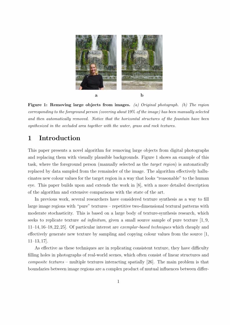
a b
Figure 1: Removing large objects from images. (a) Original photograph. (b) The region
corresponding to the foreground person (covering about 19% of the image) has been manually selected
and then automatically removed. Notice that the horizontal structures of the fountain have been
synthesized in the occluded area together with the water, grass and rock textures.
1 Introduction
This paper presents a novel algorithm for removing large objects from digital photographs
and replacing them with visually plausible backgrounds. Figure 1 shows an example of this
task, where the foreground person (manually selected as the target region) is autonatically
replaced by data sampled from the remainder of the image. The algorithm effectively hallu-
cinates new colour values for the target region in a way that looks “reasonable” to the human
eye. This paper builds upon and extends the work in [8], with a more detailed description
of the algorithm and extensive comparisons with the state of the art.
In previous work, several researchers have considered texture synthesis as a way to fill
large image regions with “pure” textures – repetitive two-dimensional textural patterns with
moderate stochasticity. This is based on a large body of texture-synthesis research, which
seeks to replicate texture ad infinitum, given a small source sample of pure texture [1, 9,
11–14,16–18,22,25]. Of particular interest are exemplar-based techniques which cheaply and
effectively generate new texture by sampling and copying colour values from the source [1,
11–13,17].
As effective as these techniques are in replicating consistent texture, they have difficulty
filling holes in photographs of real-world scenes, which often consist of linear structures and
composite textures – multiple textures interacting spatially [26]. The main problem is that
boundaries between image regions are a complex product of mutual influences between differ-
1
ent textures. In constrast to the two-dimensional nature of pure textures, these boundaries
form what might be considered more one-dimensional, or linear, image structures.
A number of algorithms specifically address the image filling issue for the task of image
restoration, where speckles, scratches, and overlaid text are removed [2–4,7,23]. These image
inpainting techniques fill holes in images by propagating linear structures (called isophotes in
the inpainting literature) into the target region via diffusion. They are inspired by the partial
differential equations of physical heat flow, and work convincingly as restoration algorithms.
Their drawback is that the diffusion process introduces some blur, which becomes noticeable
when filling larger regions.
The technique presented here combines the strengths of both approaches into a single,
efficient algorithm. As with inpainting, we pay special attention to linear structures. But,
linear structures abutting the target region only influence the fill order of what is at core
an exemplar-based texture synthesis algorithm. The result is an algorithm that has the
efficiency and qualitative performance of exemplar-based texture synthesis, but which also
respects the image constraints imposed by surrounding linear structures.
The algorithm we propose in this paper builds on very recent research along similar
lines. The work in [5] decomposes the original image into two components; one of which is
processed by inpainting and the other by texture synthesis. The output image is the sum of
the two processed components. This approach still remains limited to the removal of small
image gaps, however, as the diffusion process continues to blur the filled region (cf. [5], fig.5
top right). The automatic switching between “pure texture-” and “pure structure-mode”
described in [24] is also avoided.
Similar to [5] is the work in [10], where the authors describe an algorithm that interleaves
a smooth approximation with example-based detail synthesis for image completion. Like the
work in [5] also the algorithm in [10] is extremely slow (as reported processing may take
between 83 and 158 minutes on a 384 × 256 image) and it may introduce blur artefacts (cf.
fig.8b, last row of fig.13 and fig. 16c in [10]). In this paper we present a simpler and faster
region filling algorithm which does not suffer from blur artefacts.
One of the first attempts to use exemplar-based synthesis specifically for object removal
was by Harrison [15]. There, the order in which a pixel in the target region is filled was
dictated by the level of “texturedness” of the pixel’s neighborhood1. Although the intuition
is sound, strong linear structures were often overruled by nearby noise, minimizing the value
of the extra computation. A related technique drove the fill order by the local shape of the
1An implementation of Harrison’s algorithm is available from www.csse.monash.edu.au/∼pfh/resynthesizer/
2
target region, but did not seek to explicitly propagate linear structures [6].
Recently Jia et al. [19] have presented a technique for filling image regions based on a
texture segmentation step and a tensor-voting algorithm for the smooth linking of structures
across holes. While the ability to synthesize curved structures is a clear advantage, two
problems characterize this approach: i) the fact that the algorithm relies on an ill-defined
segmentation preprocessing and ii) the fact that the only structures that the algorithm takes
care of are the boundaries between texture segments. Those do not necessarily correspond
to real structures in the image. The algorithm we propose propagates image edges (image
structures) directly and efficiently, and negates the need of segmentation.
Finally, Zalesny et al. [26] describe an interesting algorithm for the parallel synthesis of
composite textures. They devise a special-purpose solution for synthesizing the interface
between two “knitted” textures. In this paper we show that, in fact, only one mechanism is
sufficient for the synthesis of both pure and composite textures.
Section 2 presents the two key observations which form the basis of our algorithm. The
details of the proposed algorithm are described in section 3. Finally, a large gallery of results
on both synthetic images and real-scene photographs is presented in section 4. Whenever
possible our results are compared to the ones obtained by state of the art techniques.
2 Key observations
2.1 Exemplar-based synthesis suffices
The core of our algorithm is an isophote-driven image-sampling process. It is well-understood
that exemplar-based approaches perform well for two-dimensional textures [1,11,17]. But, we
note in addition that exemplar-based texture synthesis is sufficient for propagating extended
linear image structures, as well; i.e., a separate synthesis mechanism is not required for
handling isophotes.
Figure 2 illustrates this point. For ease of comparison, we adopt notation similar to that
used in the inpainting literature. The region to be filled, i.e., the target region is indicated by
Ω, and its contour is denoted δΩ. The contour evolves inward as the algorithm progresses,
and so we also refer to it as the “fill front”. The source region, Φ, which remains fixed
throughout the algorithm, provides samples used in the filling process.
We now focus on a single iteration of the algorithm to show how structure and texture are
adequately handled by exemplar-based synthesis. Suppose that the square template Ψp ∈ Ω
3
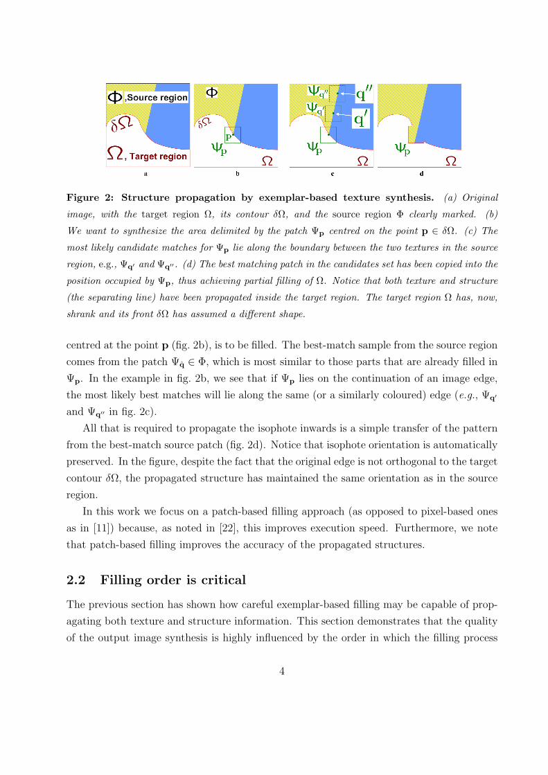
Figure 2: Structure propagation by exemplar-based texture synthesis. (a) Original
image, with the target region Ω, its contour δΩ, and the source region Φ clearly marked. (b)
We want to synthesize the area delimited by the patch Ψp centred on the point p ∈ δΩ. (c) The
most likely candidate matches for Ψp lie along the boundary between the two textures in the source
region, e.g., Ψq′ and Ψq′′. (d) The best matching patch in the candidates set has been copied into the
position occupied by Ψp, thus achieving partial filling of Ω. Notice that both texture and structure
(the separating line) have been propagated inside the target region. The target region Ω has, now,
shrank and its front δΩ has assumed a different shape.
centred at the point p (fig. 2b), is to be filled. The best-match sample from the source region
comes from the patch Ψq ∈ Φ, which is most similar to those parts that are already filled in
Ψp. In the example in fig. 2b, we see that if Ψp lies on the continuation of an image edge,
the most likely best matches will lie along the same (or a similarly coloured) edge (e.g., Ψq′
and Ψq′′ in fig. 2c).
All that is required to propagate the isophote inwards is a simple transfer of the pattern
from the best-match source patch (fig. 2d). Notice that isophote orientation is automatically
preserved. In the figure, despite the fact that the original edge is not orthogonal to the target
contour δΩ, the propagated structure has maintained the same orientation as in the source
region.
In this work we focus on a patch-based filling approach (as opposed to pixel-based ones
as in [11]) because, as noted in [22], this improves execution speed. Furthermore, we note
that patch-based filling improves the accuracy of the propagated structures.
2.2 Filling order is critical
The previous section has shown how careful exemplar-based filling may be capable of prop-
agating both texture and structure information. This section demonstrates that the quality
of the output image synthesis is highly influenced by the order in which the filling process
4
a
The filling process
Oni
on p
eel
b c d
Des
ider
ata
b’ c’ d’
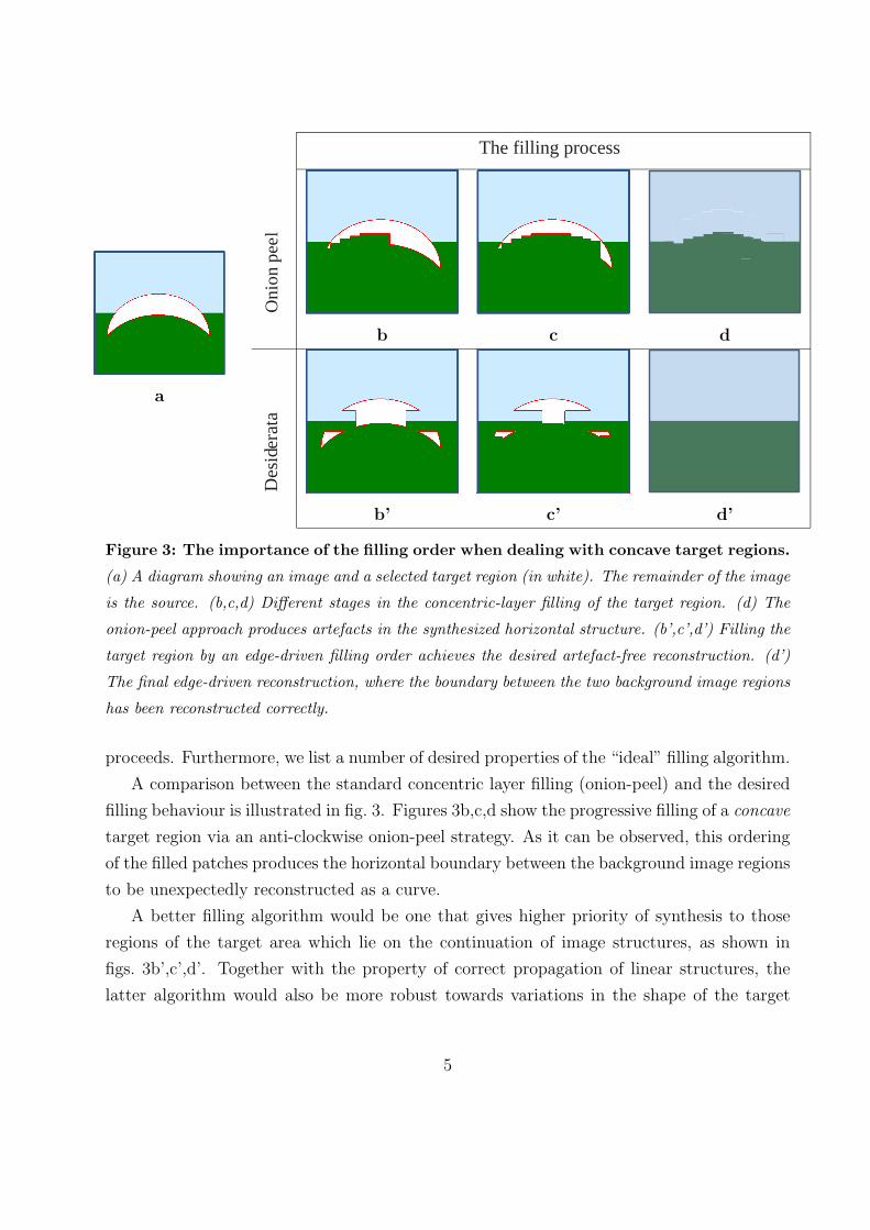
Figure 3: The importance of the filling order when dealing with concave target regions.
(a) A diagram showing an image and a selected target region (in white). The remainder of the image
is the source. (b,c,d) Different stages in the concentric-layer filling of the target region. (d) The
onion-peel approach produces artefacts in the synthesized horizontal structure. (b’,c’,d’) Filling the
target region by an edge-driven filling order achieves the desired artefact-free reconstruction. (d’)
The final edge-driven reconstruction, where the boundary between the two background image regions
has been reconstructed correctly.
proceeds. Furthermore, we list a number of desired properties of the “ideal” filling algorithm.
A comparison between the standard concentric layer filling (onion-peel) and the desired
filling behaviour is illustrated in fig. 3. Figures 3b,c,d show the progressive filling of a concave
target region via an anti-clockwise onion-peel strategy. As it can be observed, this ordering
of the filled patches produces the horizontal boundary between the background image regions
to be unexpectedly reconstructed as a curve.
A better filling algorithm would be one that gives higher priority of synthesis to those
regions of the target area which lie on the continuation of image structures, as shown in
figs. 3b’,c’,d’. Together with the property of correct propagation of linear structures, the
latter algorithm would also be more robust towards variations in the shape of the target
5
a b c
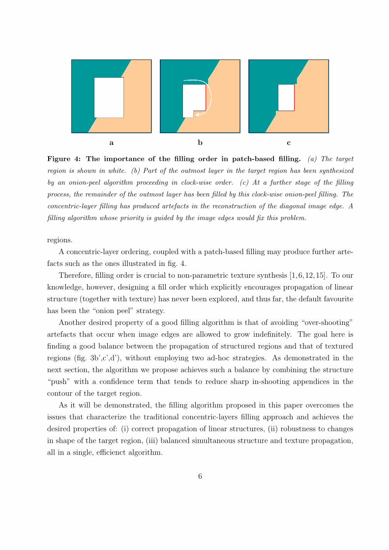
Figure 4: The importance of the filling order in patch-based filling. (a) The target
region is shown in white. (b) Part of the outmost layer in the target region has been synthesized
by an onion-peel algorithm proceeding in clock-wise order. (c) At a further stage of the filling
process, the remainder of the outmost layer has been filled by this clock-wise onion-peel filling. The
concentric-layer filling has produced artefacts in the reconstruction of the diagonal image edge. A
filling algorithm whose priority is guided by the image edges would fix this problem.
regions.
A concentric-layer ordering, coupled with a patch-based filling may produce further arte-
facts such as the ones illustrated in fig. 4.
Therefore, filling order is crucial to non-parametric texture synthesis [1,6,12,15]. To our
knowledge, however, designing a fill order which explicitly encourages propagation of linear
structure (together with texture) has never been explored, and thus far, the default favourite
has been the “onion peel” strategy.
Another desired property of a good filling algorithm is that of avoiding “over-shooting”
artefacts that occur when image edges are allowed to grow indefinitely. The goal here is
finding a good balance between the propagation of structured regions and that of textured
regions (fig. 3b’,c’,d’), without employing two ad-hoc strategies. As demonstrated in the
next section, the algorithm we propose achieves such a balance by combining the structure
“push” with a confidence term that tends to reduce sharp in-shooting appendices in the
contour of the target region.
As it will be demonstrated, the filling algorithm proposed in this paper overcomes the
issues that characterize the traditional concentric-layers filling approach and achieves the
desired properties of: (i) correct propagation of linear structures, (ii) robustness to changes
in shape of the target region, (iii) balanced simultaneous structure and texture propagation,
all in a single, efficienct algorithm.
6
We now proceed with the details of our algorithm.
3 Our region-filling algorithm
First, given an input image, the user selects a target region, Ω, to be removed and filled. The
source region, Φ, may be defined as the entire image minus the target region (Φ = I − Ω),
as a dilated band around the target region, or it may be manually specified by the user.
Next, as with all exemplar-based texture synthesis [12], the size of the template window
Ψ must be specified. We provide a default window size of 9×9 pixels, but in practice require
the user to set it to be slightly larger than the largest distinguishable texture element, or
“texel”, in the source region.
Once these parameters are determined, the region-filling proceeds automatically.
In our algorithm, each pixel maintains a colour value (or “empty”, if the pixel is unfilled)
and a confidence value, which reflects our confidence in the pixel value, and which is frozen
once a pixel has been filled. During the course of the algorithm, patches along the fill front
are also given a temporary priority value, which determines the order in which they are filled.
Then, our algorithm iterates the following three steps until all pixels have been filled:
1. Computing patch priorities Our algorithm performs the synthesis task through a
best-first filling strategy that depends entirely on the priority values that are assigned to
each patch on the fill front. The priority computation is biased toward those patches which:
(i) are on the continuation of strong edges and (ii) are surrounded by high-confidence pixels.
Given a patch Ψp centred at the point p for some p ∈ δΩ (see fig. 5), we define its
priority P (p) as the product of two terms:
P (p) = C(p)D(p). (1)
We call C(p) the confidence term and D(p) the data term, and they are defined as follows:
C(p) =
∑q∈Ψp∩(I−Ω) C(q)
|Ψp| , D(p) =|∇I⊥
p · np|α
where |Ψp| is the area of Ψp, α is a normalization factor (e.g., α = 255 for a typical grey-level
image), np is a unit vector orthogonal to the front δΩ in the point p and ⊥ denotes the
orthogonal operator. The priority P (p) is computed for every border patch, with distinct
patches for each pixel on the boundary of the target region.
7
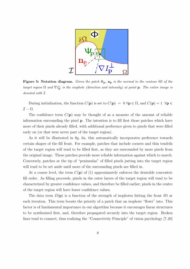
Figure 5: Notation diagram. Given the patch Ψp, np is the normal to the contour δΩ of the
target region Ω and ∇I⊥p is the isophote (direction and intensity) at point p. The entire image is
denoted with I.
During initialization, the function C(p) is set to C(p) = 0 ∀p ∈ Ω, and C(p) = 1 ∀p ∈I − Ω.
The confidence term C(p) may be thought of as a measure of the amount of reliable
information surrounding the pixel p. The intention is to fill first those patches which have
more of their pixels already filled, with additional preference given to pixels that were filled
early on (or that were never part of the target region).
As it will be illustrated in fig. 6a, this automatically incorporates preference towards
certain shapes of the fill front. For example, patches that include corners and thin tendrils
of the target region will tend to be filled first, as they are surrounded by more pixels from
the original image. These patches provide more reliable information against which to match.
Conversely, patches at the tip of “peninsulas” of filled pixels jutting into the target region
will tend to be set aside until more of the surrounding pixels are filled in.
At a coarse level, the term C(p) of (1) approximately enforces the desirable concentric
fill order. As filling proceeds, pixels in the outer layers of the target region will tend to be
characterized by greater confidence values, and therefore be filled earlier; pixels in the centre
of the target region will have lesser confidence values.
The data term D(p) is a function of the strength of isophotes hitting the front δΩ at
each iteration. This term boosts the priority of a patch that an isophote “flows” into. This
factor is of fundamental importance in our algorithm because it encourages linear structures
to be synthesized first, and, therefore propagated securely into the target region. Broken
lines tend to connect, thus realizing the “Connectivity Principle” of vision psychology [7,20]
8
(cf. fig. 7, fig. 11f’, fig. 13b and fig. 19f’).
2. Propagating texture and structure information Once all priorities on the fill front
have been computed, the patch Ψp with highest priority is found. We then fill it with data
extracted from the source region Φ.
In traditional inpainting techniques, pixel-value information is propagated via diffusion.
As noted previously, diffusion necessarily leads to image smoothing, which results in blurry
fill-in, especially of large regions (see fig. 15f).
On the contrary, we propagate image texture by direct sampling of the source region.
Similar to [12], we search in the source region for that patch which is most similar to Ψp.2
Formally,
Ψq = arg minΨq∈Φ
d(Ψp, Ψq) (2)
where the distance d(Ψa, Ψb) between two generic patches Ψa and Ψb is simply defined as
the sum of squared differences (SSD) of the already filled pixels in the two patches. Pixel
colours are represented in the CIE Lab colour space because of its property of perceptual
uniformity [21].
Having found the source exemplar Ψq, the value of each pixel-to-be-filled, p′ |p′ ∈ Ψp∩Ω,
is copied from its corresponding position inside Ψq.
This suffices to achieve the propagation of both structure and texture information from
the source Φ to the target region Ω, one patch at a time (cf., fig. 2d). In fact, we note that
any further manipulation of the pixel values (e.g., adding noise, smoothing and so forth)
that does not explicitly depend upon statistics of the source region, is more likely to degrade
visual similarity between the filled region and the source region, than to improve it.
3. Updating confidence values After the patch Ψp has been filled with new pixel values,
the confidence C(p) is updated in the area delimited by Ψp as follows:
C(p) = C(p) ∀p ∈ Ψp ∩ Ω.
This simple update rule allows us to measure the relative confidence of patches on the
fill front, without image-specific parameters. As filling proceeds, confidence values decay,
indicating that we are less sure of the colour values of pixels near the centre of the target
region.
2Valid patches must be entirely contained in Φ.
9
a b
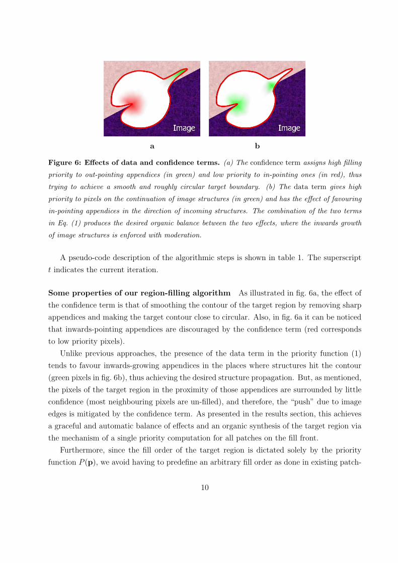
Figure 6: Effects of data and confidence terms. (a) The confidence term assigns high filling
priority to out-pointing appendices (in green) and low priority to in-pointing ones (in red), thus
trying to achieve a smooth and roughly circular target boundary. (b) The data term gives high
priority to pixels on the continuation of image structures (in green) and has the effect of favouring
in-pointing appendices in the direction of incoming structures. The combination of the two terms
in Eq. (1) produces the desired organic balance between the two effects, where the inwards growth
of image structures is enforced with moderation.
A pseudo-code description of the algorithmic steps is shown in table 1. The superscript
t indicates the current iteration.
Some properties of our region-filling algorithm As illustrated in fig. 6a, the effect of
the confidence term is that of smoothing the contour of the target region by removing sharp
appendices and making the target contour close to circular. Also, in fig. 6a it can be noticed
that inwards-pointing appendices are discouraged by the confidence term (red corresponds
to low priority pixels).
Unlike previous approaches, the presence of the data term in the priority function (1)
tends to favour inwards-growing appendices in the places where structures hit the contour
(green pixels in fig. 6b), thus achieving the desired structure propagation. But, as mentioned,
the pixels of the target region in the proximity of those appendices are surrounded by little
confidence (most neighbouring pixels are un-filled), and therefore, the “push” due to image
edges is mitigated by the confidence term. As presented in the results section, this achieves
a graceful and automatic balance of effects and an organic synthesis of the target region via
the mechanism of a single priority computation for all patches on the fill front.
Furthermore, since the fill order of the target region is dictated solely by the priority
function P (p), we avoid having to predefine an arbitrary fill order as done in existing patch-
10
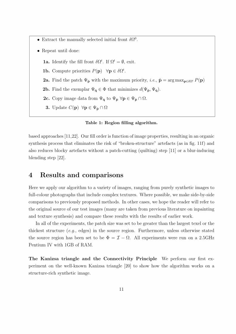
• Extract the manually selected initial front δΩ0.
• Repeat until done:
1a. Identify the fill front δΩt. If Ωt = ∅, exit.
1b. Compute priorities P (p) ∀p ∈ δΩt.
2a. Find the patch Ψp with the maximum priority, i.e., p = arg maxp∈δΩt P (p)
2b. Find the exemplar Ψq ∈ Φ that minimizes d(Ψp, Ψq).
2c. Copy image data from Ψq to Ψp ∀p ∈ Ψp ∩ Ω.
3. Update C(p) ∀p ∈ Ψp ∩ Ω
Table 1: Region filling algorithm.
based approaches [11,22]. Our fill order is function of image properties, resulting in an organic
synthesis process that eliminates the risk of “broken-structure” artefacts (as in fig. 11f) and
also reduces blocky artefacts without a patch-cutting (quilting) step [11] or a blur-inducing
blending step [22].
4 Results and comparisons
Here we apply our algorithm to a variety of images, ranging from purely synthetic images to
full-colour photographs that include complex textures. Where possible, we make side-by-side
comparisons to previously proposed methods. In other cases, we hope the reader will refer to
the original source of our test images (many are taken from previous literature on inpainting
and texture synthesis) and compare these results with the results of earlier work.
In all of the experiments, the patch size was set to be greater than the largest texel or the
thickest structure (e.g., edges) in the source region. Furthermore, unless otherwise stated
the source region has been set to be Φ = I − Ω. All experiments were run on a 2.5GHz
Pentium IV with 1GB of RAM.
The Kanizsa triangle and the Connectivity Principle We perform our first ex-
periment on the well-known Kanizsa triangle [20] to show how the algorithm works on a
structure-rich synthetic image.
11
a b c d e f g
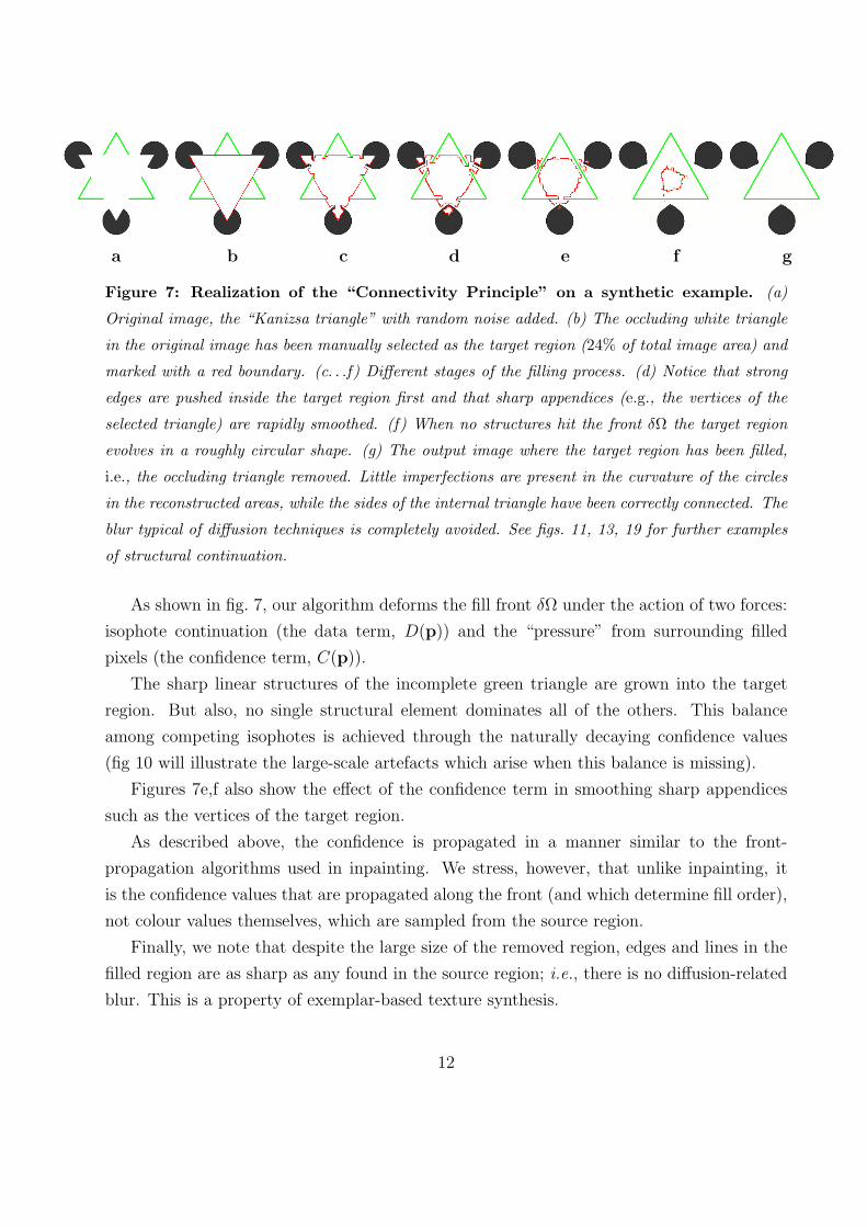
Figure 7: Realization of the “Connectivity Principle” on a synthetic example. (a)
Original image, the “Kanizsa triangle” with random noise added. (b) The occluding white triangle
in the original image has been manually selected as the target region (24% of total image area) and
marked with a red boundary. (c. . .f) Different stages of the filling process. (d) Notice that strong
edges are pushed inside the target region first and that sharp appendices (e.g., the vertices of the
selected triangle) are rapidly smoothed. (f) When no structures hit the front δΩ the target region
evolves in a roughly circular shape. (g) The output image where the target region has been filled,
i.e., the occluding triangle removed. Little imperfections are present in the curvature of the circles
in the reconstructed areas, while the sides of the internal triangle have been correctly connected. The
blur typical of diffusion techniques is completely avoided. See figs. 11, 13, 19 for further examples
of structural continuation.
As shown in fig. 7, our algorithm deforms the fill front δΩ under the action of two forces:
isophote continuation (the data term, D(p)) and the “pressure” from surrounding filled
pixels (the confidence term, C(p)).
The sharp linear structures of the incomplete green triangle are grown into the target
region. But also, no single structural element dominates all of the others. This balance
among competing isophotes is achieved through the naturally decaying confidence values
(fig 10 will illustrate the large-scale artefacts which arise when this balance is missing).
Figures 7e,f also show the effect of the confidence term in smoothing sharp appendices
such as the vertices of the target region.
As described above, the confidence is propagated in a manner similar to the front-
propagation algorithms used in inpainting. We stress, however, that unlike inpainting, it
is the confidence values that are propagated along the front (and which determine fill order),
not colour values themselves, which are sampled from the source region.
Finally, we note that despite the large size of the removed region, edges and lines in the
filled region are as sharp as any found in the source region; i.e., there is no diffusion-related
blur. This is a property of exemplar-based texture synthesis.
12
a b c d e f
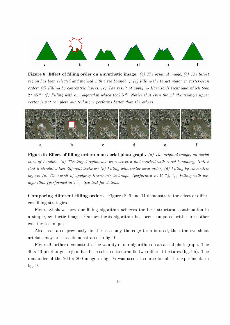
Figure 8: Effect of filling order on a synthetic image. (a) The original image; (b) The target
region has been selected and marked with a red boundary; (c) Filling the target region in raster-scan
order; (d) Filling by concentric layers; (e) The result of applying Harrison’s technique which took
2 ′ 45 ′′; (f) Filling with our algorithm which took 5 ′′. Notice that even though the triangle upper
vertex is not complete our technique performs better than the others.
a b c d e f
Figure 9: Effect of filling order on an aerial photograph. (a) The original image, an aerial
view of London. (b) The target region has been selected and marked with a red boundary; Notice
that it straddles two different textures; (c) Filling with raster-scan order; (d) Filling by concentric
layers; (e) The result of applying Harrison’s technique (performed in 45 ′′); (f) Filling with our
algorithm (performed in 2 ′′). See text for details.
Comparing different filling orders Figures 8, 9 and 11 demonstrate the effect of differ-
ent filling strategies.
Figure 8f shows how our filling algorithm achieves the best structural continuation in
a simple, synthetic image. Our synthesis algorithm has been compared with three other
existing techniques.
Also, as stated previously, in the case only the edge term is used, then the overshoot
artefact may arise, as demonstrated in fig 10.
Figure 9 further demonstrates the validity of our algorithm on an aerial photograph. The
40× 40-pixel target region has been selected to straddle two different textures (fig. 9b). The
remainder of the 200 × 200 image in fig. 9a was used as source for all the experiments in
fig. 9.
13
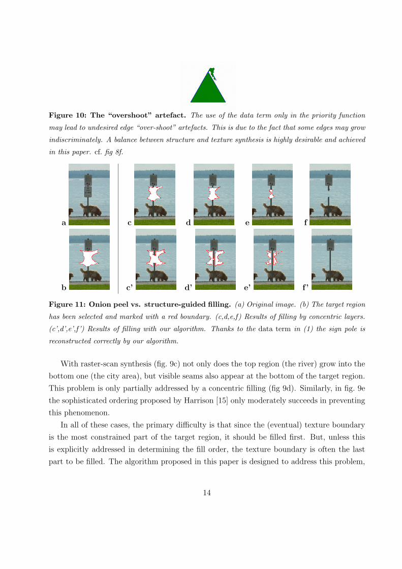
Figure 10: The “overshoot” artefact. The use of the data term only in the priority function
may lead to undesired edge “over-shoot” artefacts. This is due to the fact that some edges may grow
indiscriminately. A balance between structure and texture synthesis is highly desirable and achieved
in this paper. cf. fig 8f.
a
b
c d e f
c’ d’ e’ f ’
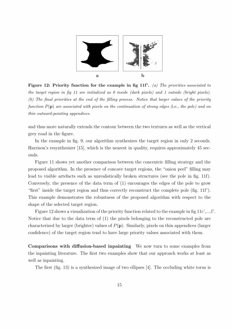
Figure 11: Onion peel vs. structure-guided filling. (a) Original image. (b) The target region
has been selected and marked with a red boundary. (c,d,e,f) Results of filling by concentric layers.
(c’,d’,e’,f ’) Results of filling with our algorithm. Thanks to the data term in (1) the sign pole is
reconstructed correctly by our algorithm.
With raster-scan synthesis (fig. 9c) not only does the top region (the river) grow into the
bottom one (the city area), but visible seams also appear at the bottom of the target region.
This problem is only partially addressed by a concentric filling (fig 9d). Similarly, in fig. 9e
the sophisticated ordering proposed by Harrison [15] only moderately succeeds in preventing
this phenomenon.
In all of these cases, the primary difficulty is that since the (eventual) texture boundary
is the most constrained part of the target region, it should be filled first. But, unless this
is explicitly addressed in determining the fill order, the texture boundary is often the last
part to be filled. The algorithm proposed in this paper is designed to address this problem,
14
a b
Figure 12: Priority function for the example in fig 11f’. (a) The priorities associated to
the target region in fig 11 are initialized as 0 inside (dark pixels) and 1 outside (bright pixels).
(b) The final priorities at the end of the filling process. Notice that larger values of the priority
function P (p) are associated with pixels on the continuation of strong edges (i.e., the pole) and on
thin outward-pointing appendices.
and thus more naturally extends the contour between the two textures as well as the vertical
grey road in the figure.
In the example in fig. 9, our algorithm synthesizes the target region in only 2 seconds.
Harrison’s resynthesizer [15], which is the nearest in quality, requires approximately 45 sec-
onds.
Figure 11 shows yet another comparison between the concentric filling strategy and the
proposed algorithm. In the presence of concave target regions, the “onion peel” filling may
lead to visible artefacts such as unrealistically broken structures (see the pole in fig. 11f).
Conversely, the presence of the data term of (1) encourages the edges of the pole to grow
“first” inside the target region and thus correctly reconstruct the complete pole (fig. 11f’).
This example demonstrates the robustness of the proposed algorithm with respect to the
shape of the selected target region.
Figure 12 shows a visualization of the priority function related to the example in fig 11c’,...,f’.
Notice that due to the data term of (1) the pixels belonging to the reconstructed pole are
characterized by larger (brighter) values of P (p). Similarly, pixels on thin appendices (larger
confidence) of the target region tend to have large priority values associated with them.
Comparisons with diffusion-based inpainting We now turn to some examples from
the inpainting literature. The first two examples show that our approach works at least as
well as inpainting.
The first (fig. 13) is a synthesized image of two ellipses [4]. The occluding white torus is
15
a b
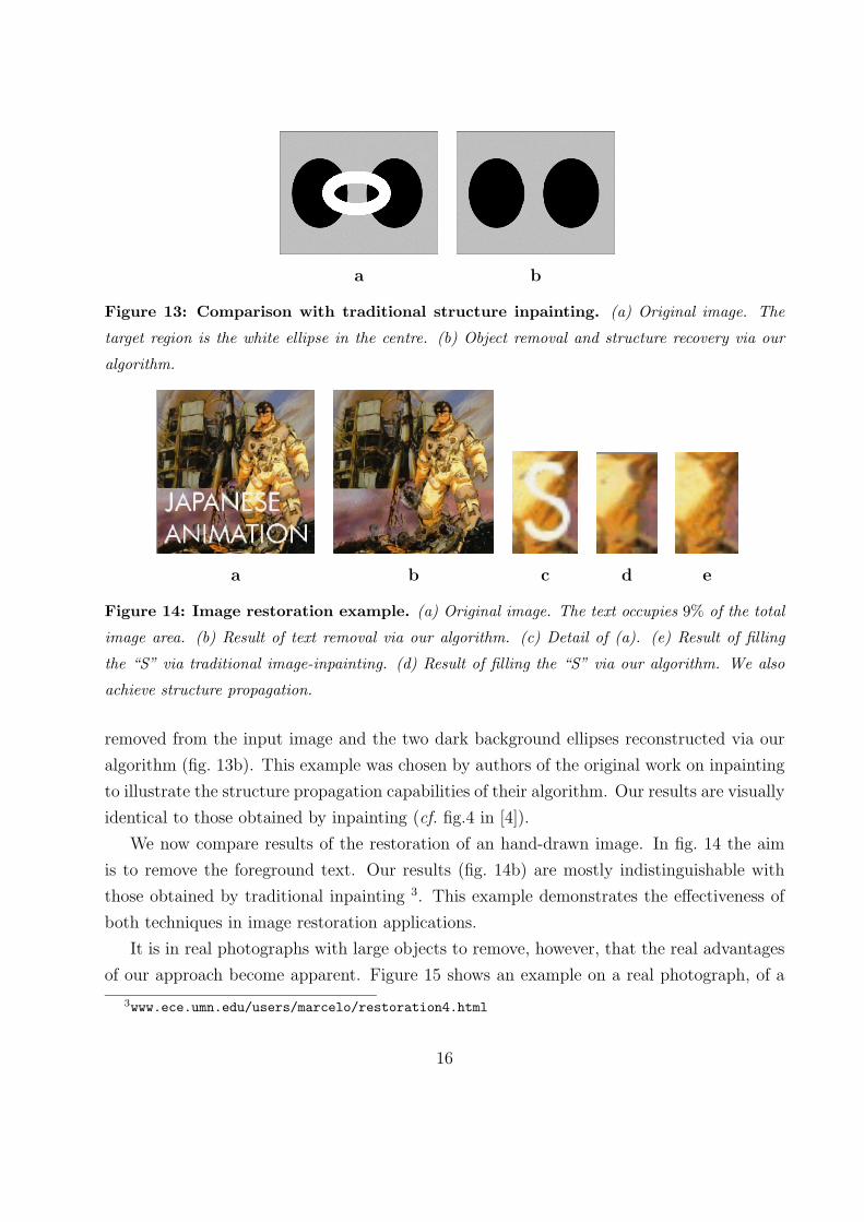
Figure 13: Comparison with traditional structure inpainting. (a) Original image. The
target region is the white ellipse in the centre. (b) Object removal and structure recovery via our
algorithm.
a b c d e
Figure 14: Image restoration example. (a) Original image. The text occupies 9% of the total
image area. (b) Result of text removal via our algorithm. (c) Detail of (a). (e) Result of filling
the “S” via traditional image-inpainting. (d) Result of filling the “S” via our algorithm. We also
achieve structure propagation.
removed from the input image and the two dark background ellipses reconstructed via our
algorithm (fig. 13b). This example was chosen by authors of the original work on inpainting
to illustrate the structure propagation capabilities of their algorithm. Our results are visually
identical to those obtained by inpainting (cf. fig.4 in [4]).
We now compare results of the restoration of an hand-drawn image. In fig. 14 the aim
is to remove the foreground text. Our results (fig. 14b) are mostly indistinguishable with
those obtained by traditional inpainting 3. This example demonstrates the effectiveness of
both techniques in image restoration applications.
It is in real photographs with large objects to remove, however, that the real advantages
of our approach become apparent. Figure 15 shows an example on a real photograph, of a
3www.ece.umn.edu/users/marcelo/restoration4.html
16
a b c d e f
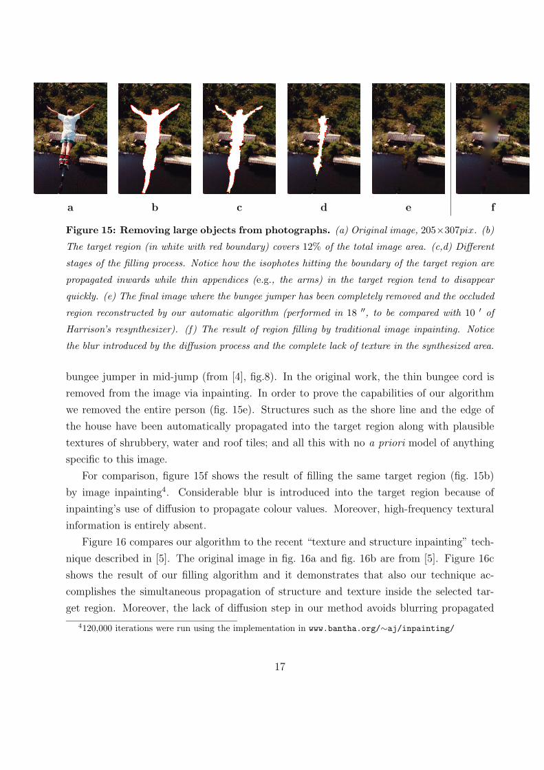
Figure 15: Removing large objects from photographs. (a) Original image, 205×307pix. (b)
The target region (in white with red boundary) covers 12% of the total image area. (c,d) Different
stages of the filling process. Notice how the isophotes hitting the boundary of the target region are
propagated inwards while thin appendices (e.g., the arms) in the target region tend to disappear
quickly. (e) The final image where the bungee jumper has been completely removed and the occluded
region reconstructed by our automatic algorithm (performed in 18 ′′, to be compared with 10 ′ of
Harrison’s resynthesizer). (f) The result of region filling by traditional image inpainting. Notice
the blur introduced by the diffusion process and the complete lack of texture in the synthesized area.
bungee jumper in mid-jump (from [4], fig.8). In the original work, the thin bungee cord is
removed from the image via inpainting. In order to prove the capabilities of our algorithm
we removed the entire person (fig. 15e). Structures such as the shore line and the edge of
the house have been automatically propagated into the target region along with plausible
textures of shrubbery, water and roof tiles; and all this with no a priori model of anything
specific to this image.
For comparison, figure 15f shows the result of filling the same target region (fig. 15b)
by image inpainting4. Considerable blur is introduced into the target region because of
inpainting’s use of diffusion to propagate colour values. Moreover, high-frequency textural
information is entirely absent.
Figure 16 compares our algorithm to the recent “texture and structure inpainting” tech-
nique described in [5]. The original image in fig. 16a and fig. 16b are from [5]. Figure 16c
shows the result of our filling algorithm and it demonstrates that also our technique ac-
complishes the simultaneous propagation of structure and texture inside the selected tar-
get region. Moreover, the lack of diffusion step in our method avoids blurring propagated
4120,000 iterations were run using the implementation in www.bantha.org/∼aj/inpainting/
17
a b c
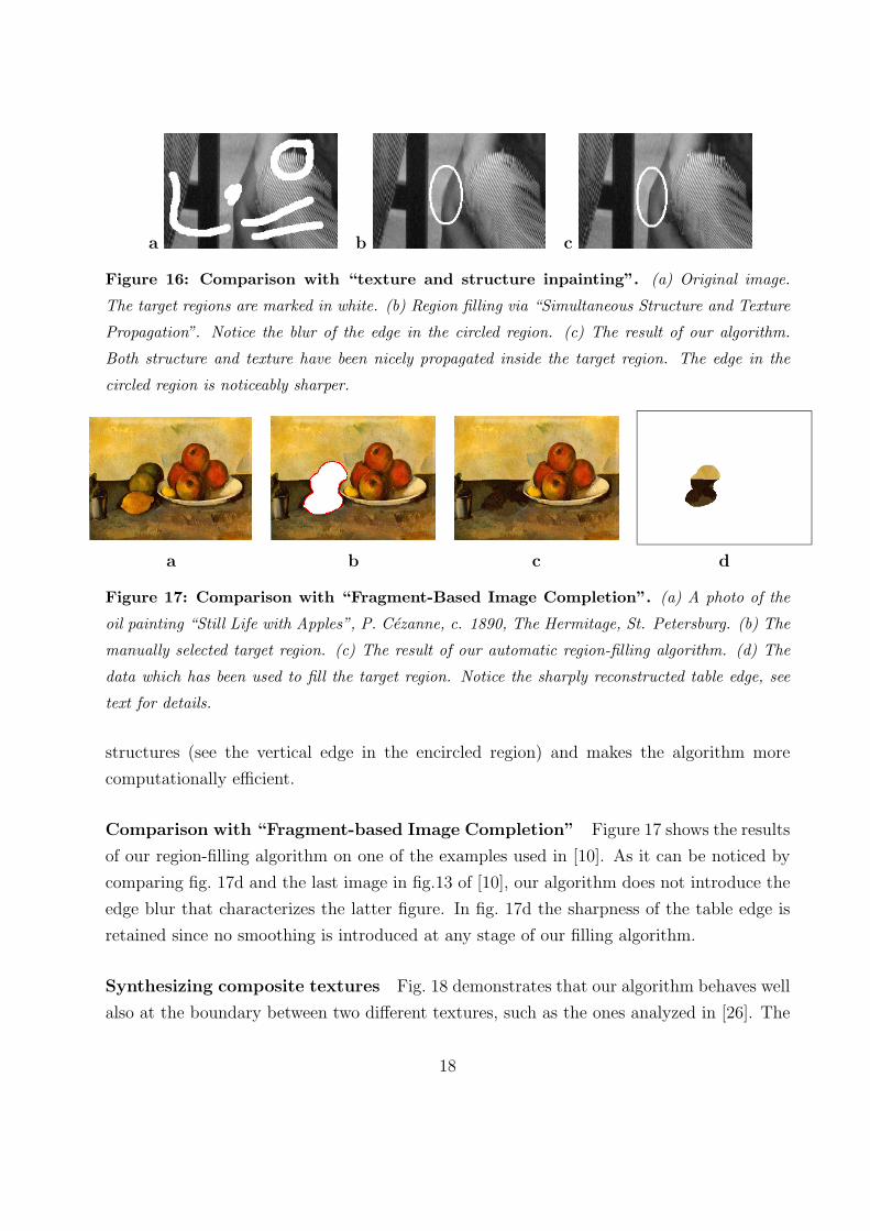
Figure 16: Comparison with “texture and structure inpainting”. (a) Original image.
The target regions are marked in white. (b) Region filling via “Simultaneous Structure and Texture
Propagation”. Notice the blur of the edge in the circled region. (c) The result of our algorithm.
Both structure and texture have been nicely propagated inside the target region. The edge in the
circled region is noticeably sharper.
a b c d
Figure 17: Comparison with “Fragment-Based Image Completion”. (a) A photo of the
oil painting “Still Life with Apples”, P. Cezanne, c. 1890, The Hermitage, St. Petersburg. (b) The
manually selected target region. (c) The result of our automatic region-filling algorithm. (d) The
data which has been used to fill the target region. Notice the sharply reconstructed table edge, see
text for details.
structures (see the vertical edge in the encircled region) and makes the algorithm more
computationally efficient.
Comparison with “Fragment-based Image Completion” Figure 17 shows the results
of our region-filling algorithm on one of the examples used in [10]. As it can be noticed by
comparing fig. 17d and the last image in fig.13 of [10], our algorithm does not introduce the
edge blur that characterizes the latter figure. In fig. 17d the sharpness of the table edge is
retained since no smoothing is introduced at any stage of our filling algorithm.
Synthesizing composite textures Fig. 18 demonstrates that our algorithm behaves well
also at the boundary between two different textures, such as the ones analyzed in [26]. The
18
a b c d
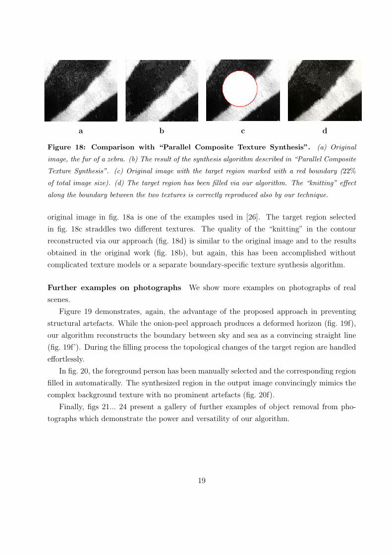
Figure 18: Comparison with “Parallel Composite Texture Synthesis”. (a) Original
image, the fur of a zebra. (b) The result of the synthesis algorithm described in “Parallel Composite
Texture Synthesis”. (c) Original image with the target region marked with a red boundary (22%
of total image size). (d) The target region has been filled via our algorithm. The “knitting” effect
along the boundary between the two textures is correctly reproduced also by our technique.
original image in fig. 18a is one of the examples used in [26]. The target region selected
in fig. 18c straddles two different textures. The quality of the “knitting” in the contour
reconstructed via our approach (fig. 18d) is similar to the original image and to the results
obtained in the original work (fig. 18b), but again, this has been accomplished without
complicated texture models or a separate boundary-specific texture synthesis algorithm.
Further examples on photographs We show more examples on photographs of real
scenes.
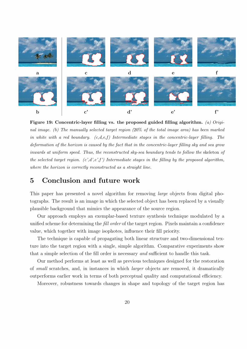
Figure 19 demonstrates, again, the advantage of the proposed approach in preventing
structural artefacts. While the onion-peel approach produces a deformed horizon (fig. 19f),
our algorithm reconstructs the boundary between sky and sea as a convincing straight line
(fig. 19f’). During the filling process the topological changes of the target region are handled
effortlessly.
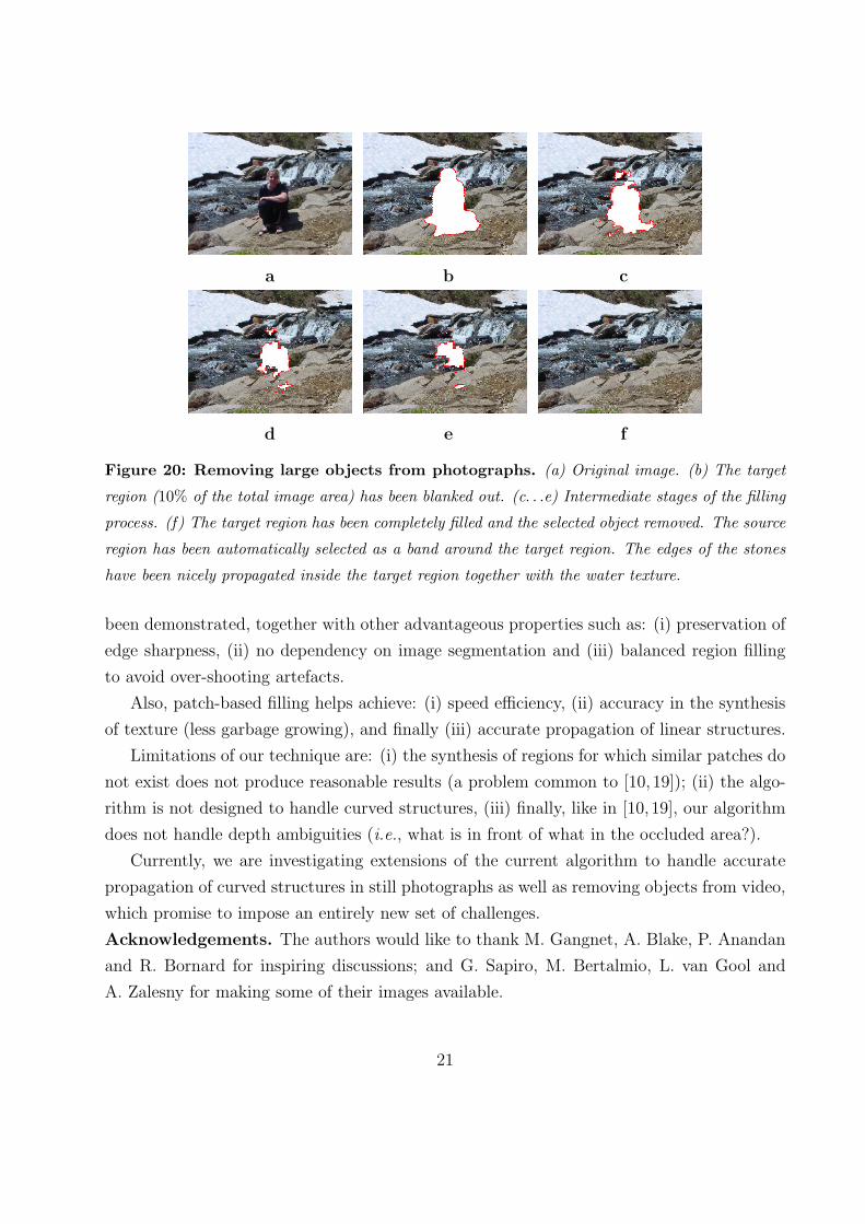
In fig. 20, the foreground person has been manually selected and the corresponding region
filled in automatically. The synthesized region in the output image convincingly mimics the
complex background texture with no prominent artefacts (fig. 20f).
Finally, figs 21... 24 present a gallery of further examples of object removal from pho-
tographs which demonstrate the power and versatility of our algorithm.
19
a
b
c d e f
c’ d’ e’ f ’
Figure 19: Concentric-layer filling vs. the proposed guided filling algorithm. (a) Origi-
nal image. (b) The manually selected target region (20% of the total image area) has been marked
in white with a red boundary. (c,d,e,f) Intermediate stages in the concentric-layer filling. The
deformation of the horizon is caused by the fact that in the concentric-layer filling sky and sea grow
inwards at uniform speed. Thus, the reconstructed sky-sea boundary tends to follow the skeleton of
the selected target region. (c’,d’,e’,f ’) Intermediate stages in the filling by the proposed algorithm,
where the horizon is correctly reconstructed as a straight line.
5 Conclusion and future work
This paper has presented a novel algorithm for removing large objects from digital pho-
tographs. The result is an image in which the selected object has been replaced by a visually
plausible background that mimics the appearance of the source region.
Our approach employs an exemplar-based texture synthesis technique modulated by a
unified scheme for determining the fill order of the target region. Pixels maintain a confidence
value, which together with image isophotes, influence their fill priority.
The technique is capable of propagating both linear structure and two-dimensional tex-
ture into the target region with a single, simple algorithm. Comparative experiments show
that a simple selection of the fill order is necessary and sufficient to handle this task.
Our method performs at least as well as previous techniques designed for the restoration
of small scratches, and, in instances in which larger objects are removed, it dramatically
outperforms earlier work in terms of both perceptual quality and computational efficiency.
Moreover, robustness towards changes in shape and topology of the target region has
20
a b c
d e f
Figure 20: Removing large objects from photographs. (a) Original image. (b) The target
region (10% of the total image area) has been blanked out. (c. . .e) Intermediate stages of the filling
process. (f) The target region has been completely filled and the selected object removed. The source
region has been automatically selected as a band around the target region. The edges of the stones
have been nicely propagated inside the target region together with the water texture.
been demonstrated, together with other advantageous properties such as: (i) preservation of
edge sharpness, (ii) no dependency on image segmentation and (iii) balanced region filling
to avoid over-shooting artefacts.
Also, patch-based filling helps achieve: (i) speed efficiency, (ii) accuracy in the synthesis
of texture (less garbage growing), and finally (iii) accurate propagation of linear structures.
Limitations of our technique are: (i) the synthesis of regions for which similar patches do
not exist does not produce reasonable results (a problem common to [10, 19]); (ii) the algo-
rithm is not designed to handle curved structures, (iii) finally, like in [10,19], our algorithm
does not handle depth ambiguities (i.e., what is in front of what in the occluded area?).
Currently, we are investigating extensions of the current algorithm to handle accurate
propagation of curved structures in still photographs as well as removing objects from video,
which promise to impose an entirely new set of challenges.
Acknowledgements. The authors would like to thank M. Gangnet, A. Blake, P. Anandan
and R. Bornard for inspiring discussions; and G. Sapiro, M. Bertalmio, L. van Gool and
A. Zalesny for making some of their images available.
21
a b
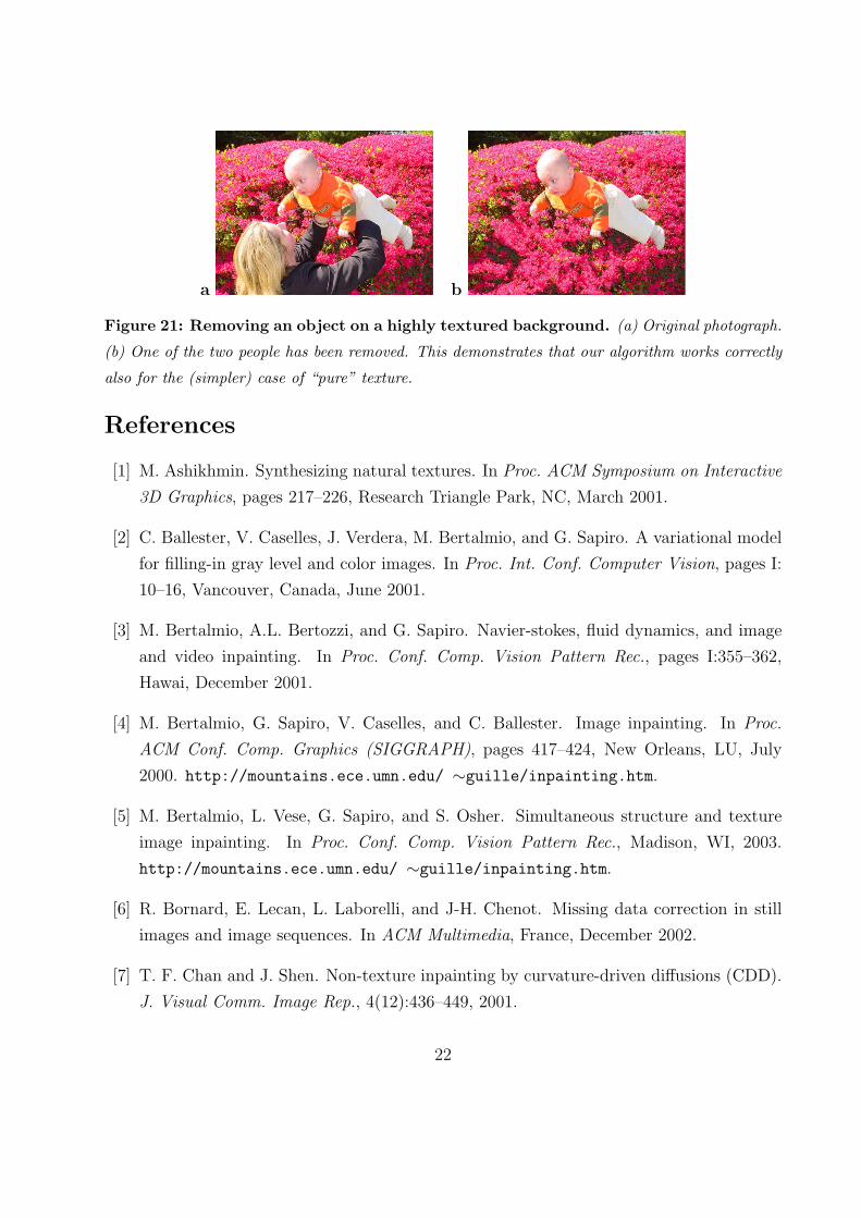
Figure 21: Removing an object on a highly textured background. (a) Original photograph.
(b) One of the two people has been removed. This demonstrates that our algorithm works correctly
also for the (simpler) case of “pure” texture.
References
[1] M. Ashikhmin. Synthesizing natural textures. In Proc. ACM Symposium on Interactive
3D Graphics, pages 217–226, Research Triangle Park, NC, March 2001.
[2] C. Ballester, V. Caselles, J. Verdera, M. Bertalmio, and G. Sapiro. A variational model
for filling-in gray level and color images. In Proc. Int. Conf. Computer Vision, pages I:
10–16, Vancouver, Canada, June 2001.
[3] M. Bertalmio, A.L. Bertozzi, and G. Sapiro. Navier-stokes, fluid dynamics, and image
and video inpainting. In Proc. Conf. Comp. Vision Pattern Rec., pages I:355–362,
Hawai, December 2001.
[4] M. Bertalmio, G. Sapiro, V. Caselles, and C. Ballester. Image inpainting. In Proc.
ACM Conf. Comp. Graphics (SIGGRAPH), pages 417–424, New Orleans, LU, July
2000. http://mountains.ece.umn.edu/ ∼guille/inpainting.htm.
[5] M. Bertalmio, L. Vese, G. Sapiro, and S. Osher. Simultaneous structure and texture
image inpainting. In Proc. Conf. Comp. Vision Pattern Rec., Madison, WI, 2003.
http://mountains.ece.umn.edu/ ∼guille/inpainting.htm.
[6] R. Bornard, E. Lecan, L. Laborelli, and J-H. Chenot. Missing data correction in still
images and image sequences. In ACM Multimedia, France, December 2002.
[7] T. F. Chan and J. Shen. Non-texture inpainting by curvature-driven diffusions (CDD).
J. Visual Comm. Image Rep., 4(12):436–449, 2001.
22
a b c d
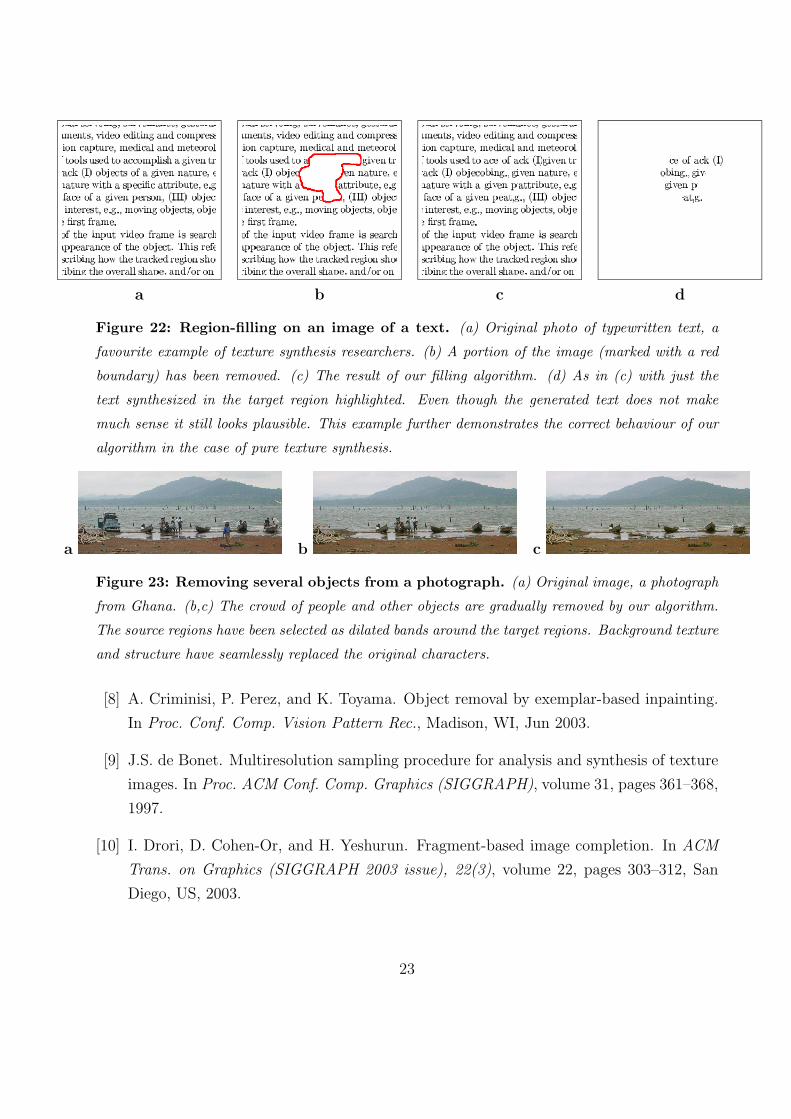
Figure 22: Region-filling on an image of a text. (a) Original photo of typewritten text, a
favourite example of texture synthesis researchers. (b) A portion of the image (marked with a red
boundary) has been removed. (c) The result of our filling algorithm. (d) As in (c) with just the
text synthesized in the target region highlighted. Even though the generated text does not make
much sense it still looks plausible. This example further demonstrates the correct behaviour of our
algorithm in the case of pure texture synthesis.
a b c
Figure 23: Removing several objects from a photograph. (a) Original image, a photograph
from Ghana. (b,c) The crowd of people and other objects are gradually removed by our algorithm.
The source regions have been selected as dilated bands around the target regions. Background texture
and structure have seamlessly replaced the original characters.
[8] A. Criminisi, P. Perez, and K. Toyama. Object removal by exemplar-based inpainting.
In Proc. Conf. Comp. Vision Pattern Rec., Madison, WI, Jun 2003.
[9] J.S. de Bonet. Multiresolution sampling procedure for analysis and synthesis of texture
images. In Proc. ACM Conf. Comp. Graphics (SIGGRAPH), volume 31, pages 361–368,
1997.
[10] I. Drori, D. Cohen-Or, and H. Yeshurun. Fragment-based image completion. In ACM
Trans. on Graphics (SIGGRAPH 2003 issue), 22(3), volume 22, pages 303–312, San
Diego, US, 2003.
23
a b c d
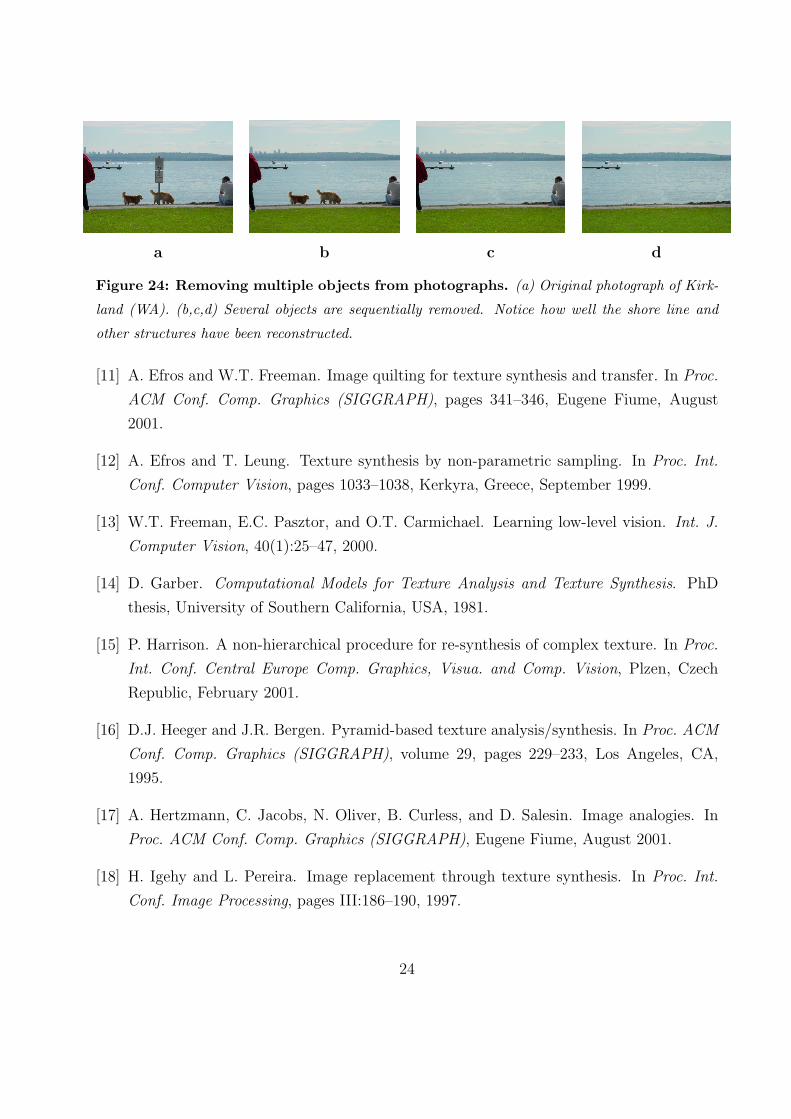
Figure 24: Removing multiple objects from photographs. (a) Original photograph of Kirk-
land (WA). (b,c,d) Several objects are sequentially removed. Notice how well the shore line and
other structures have been reconstructed.
[11] A. Efros and W.T. Freeman. Image quilting for texture synthesis and transfer. In Proc.
ACM Conf. Comp. Graphics (SIGGRAPH), pages 341–346, Eugene Fiume, August
2001.
[12] A. Efros and T. Leung. Texture synthesis by non-parametric sampling. In Proc. Int.
Conf. Computer Vision, pages 1033–1038, Kerkyra, Greece, September 1999.
[13] W.T. Freeman, E.C. Pasztor, and O.T. Carmichael. Learning low-level vision. Int. J.
Computer Vision, 40(1):25–47, 2000.
[14] D. Garber. Computational Models for Texture Analysis and Texture Synthesis. PhD
thesis, University of Southern California, USA, 1981.
[15] P. Harrison. A non-hierarchical procedure for re-synthesis of complex texture. In Proc.
Int. Conf. Central Europe Comp. Graphics, Visua. and Comp. Vision, Plzen, Czech
Republic, February 2001.
[16] D.J. Heeger and J.R. Bergen. Pyramid-based texture analysis/synthesis. In Proc. ACM
Conf. Comp. Graphics (SIGGRAPH), volume 29, pages 229–233, Los Angeles, CA,
1995.
[17] A. Hertzmann, C. Jacobs, N. Oliver, B. Curless, and D. Salesin. Image analogies. In
Proc. ACM Conf. Comp. Graphics (SIGGRAPH), Eugene Fiume, August 2001.
[18] H. Igehy and L. Pereira. Image replacement through texture synthesis. In Proc. Int.
Conf. Image Processing, pages III:186–190, 1997.
24
[19] J. Jia and C.-K. Tang. Image repairing: Robust image synthesis by adaptive nd tensor
voting. In Proc. Conf. Comp. Vision Pattern Rec., Madison, WI, 2003.
[20] G. Kanizsa. Organization in Vision. Praeger, New York, 1979.
[21] J. M. Kasson and W. Plouffe. An analysis of selected computer interchange color spaces.
In ACM Transactions on Graphics, volume 11, pages 373–405, October 1992.
[22] L. Liang, C. Liu, Y.-Q. Xu, B. Guo, and H.-Y. Shum. Real-time texture synthesis by
patch-based sampling. ACM Transactions on Graphics, 2001.
[23] S Masnou and J.-M. Morel. Level lines based disocclusion. In Int. Conf. Image Pro-
cessing, Chicago, 1998.
[24] S. Rane, G. Sapiro, and M. Bertalmio. Structure and texture filling-in of missing image
blocks in wireless transmission and compression applications. In IEEE. Trans. Image
Processing, 2002. to appear.
[25] L.-W. Wey and M. Levoy. Fast texture synthesis using tree-structured vector quantiza-
tion. In Proc. ACM Conf. Comp. Graphics (SIGGRAPH), 2000.
[26] A. Zalesny, V. Ferrari, G. Caenen, and L. van Gool. Parallel composite texture synthesis.
In Texture 2002 workshop - ECCV, Copenhagen, Denmark, June 2002.
25