reflex and healing architecture for software health management and healing... · reflex and healing...
TRANSCRIPT

Reflex and Healing Architecture for Software Health Management
Abhishek Dubey
Nagbhushan Mahadevan
Robert Kereskenyi
1
First International Workshop on Software Health Management, July 2009

Rise in Software Complexity• Software used in complex systems such
as avionics has increased in size and complexity over last four decades.
• A large number of functionalities in these systems are implemented in software.
• Reliability of the system is contingent upon
– Dependability of the embedded computing system
– Dependability of the software implementing the logic
First International Workshop on Software Health Management, July 2009
2
“Orion flight software size estimatesexceed 1 million lines of code, whichmeans that it will be more than 100 timeslarger than Apollo flight software and willrun on avionics with thousands of timesthe RAM and CPU performance of theApollo avionics.”
From NASA Study on Flight Software Complexity - May 2009.http://oceexternal.nasa.gov/OCE_LIB/pdf/1021608main_FSWC_Final_Report.pdf
Cause of outage 1985 1987 1989
Hardware failure + Environment 35% 32% 13%
Software failure 34% 39% 62%
Maintenance and operations 27% 24% 20%
Unknown 4% 5% 5%
Trends from the past (Jim Gray’s census in 1990)
“Software faults cost the U.S. economy $59.5 billion annually, representing 0.6% of the US gross domestic product” *NIST2002+

Software Health Management• Software can have latent faults, uncaught by testing and verification. Such faults
become apparent during operation when unforeseen modes and/or (system) faults appear.
• SHM: Apply concepts and techniques of physical system health management such as FDIR to software integrated systems.
• There are differences between physical systems and software systems
3
1. Physical systems (continuous) are governed by differential equations
2. State space is implicitly specified (symbolically).
3. Faults appear as change in value of parameters. For incipient faults, the discrepancy in observation is gradual.
4. State space, even though infinite is symbolically explored using real analysis.
5. Prognosis involves predicting the future system states based on change in parameters and environment input
1. Software is typically governed by a timeddiscrete event system model.
2. Representing state space is a potential challenge. Often a combination of symbolic and explicit specification is used.
3. Faults appear when the system transitions to a faulty state. This transition is instantaneous.
4. State space is often very large and has to be usually explored via model-checking using various abstractions.
5. Prognosis involves predicting the set of traces that might eventually lead to a failure state.

Reflex and Healing Approach: (Runtime Management)
• Developed for managing the filter farm for a large physics experiment. The farm had to process ~1-2TB/s of data over 2x10⁷
channels, and use ~2500 embedded processors with an additional ~2500-node commodity cluster.
• Strict real-time deadlines, as the interactions within the particle accelerator are produced by a well known periodic process
• Data is reduced over several “levels” by the data collection system in an effort to store only the most scientifically interesting interactions
• Reflex (Reactive): A fast, involuntary, preprogrammed, localized response to stimuli
• Using the timed discrete event system model of software.
• Depending upon history of executed events, the reflex action is achieved by driving the system to a desirable state by externally issued events
• e.g. changing the resolution parameter of a software sensor component if it is taking too long to process.
• Healing (Planning): Coordinated, long term adaptation of systems to recover from adverse conditions
Abhishek Dubey, Steve Nordstrom, Turker Keskinpala, Sandeep Neema, Ted Bapty, and Gabor Karsai. “Towards a verifiable real-time, autonomic, fault mitigation framework for large scale real-time systems”. Innovations in Systems and Software Engineering, Volume 3, pages 33–52, March 2007.

Runtime Fault Detection• Faults are detected through the observation of
discrepancies which are deviations from the expected behavior. – Requires the specification of properties in the
value-domain and temporal domain.
• Untimed Properties– Propositional logic (AvailRAM>50%)– Predicate logic (AvailRAM(pion1)>50%)– Temporal logic (AG AvailRAM(pion1)>50%)
• Timed properties – TCTL logic – AG (AvailRAM(pion1)<50% → AF<=5 AvailRAM(pion1)>50%)
5
The value-domain properties require monitoring of current values associated with computation resources

Reflex and Healing Architecture
• Sensors are software as well as hardware components generating timed event traces.
• Reflex engines have two components: monitors and mitigators.
• Hierarchical arrangement with strict interaction constraints for fault containment and scalability
• Fault are detected as discrepancies
– Violation of the timed property used to create the monitor.
• Mitigation via action scripts associated with the timed state machines of actuators.
– A timeout is generated if the action script does not finish in the bounded time.
GlobalManager
RegionalManager
LocalManager
LocalManager
LocalManager
LocalManager
Sensors
OtherApplications
Sensors SensorsSensors
Embedded ComputingNode1
Node2 Node3 Node4
Regional zone 1
Regional zone 2
Other Applications
Other Applications
Other Applications
DB
Link to and from Database
Periodic –Time period
Heartbeat
Other SensorsOn-demand
aperiodic
Nominal
Detect
Diagnose
MitigateRegionalManager
Mitigation Engine
Sensors
6
Operating System
Hardware
User Space
User
TasksSens
orFilter
Sens
orFilter
Sensor
Scheduler
...
One Process
Scheduler
:
Event-
Based
Monitor1Monitor1
Monitor1
Scheduler
:
Event-
Based
Monitor
1Monitor
1Fault
Mitigation
StrategyOne Process One Process
Reflex Engine
Module
Event Buffer Event Buffer
Timer Timer

Reflex Demonstrations• First, a system was modeled and deployed whereby components
and dataflow interactions were modeled and deployed on a network of 16 embedded DSP processors
– The mitigation behaviors of this system were static and created by hand– The system was able to recover from a variety of failure scenarios. A live
demonstration of this system, including the tools used to create and deploy it, was given at the Fermilab/SLAC exhibit floor at SuperComputer2003 (SC2003)
• Then, another system of larger scale was proposed, built, and deployed on a 84-node cluster located at Fermi National Laboratory.
– Cluster was comprised of systems which had been decommissioned from other clusters due to known failures
– A set of fault mitigation scenarios were successfully demonstrated at the FALSE-II workshop, co-located with the Real Time Applications Symposium(RTAS 2005).
– Behaviors which implemented all of the recovery actions were modeled in the design tools as reflexes within a RH Architecture
– Components to implement the behaviors were automatically generated and deployed throughout the system exclusively from models
• Recently, we have also implemented this architecture for large scientific computing clusters located at Fermi National Laboratory.
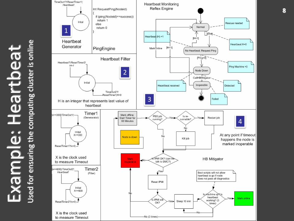
8Ex
amp
le: H
eart
bea
tU
sed
fo
r en
suri
ng
the
com
pu
tin
g cl
ust
er is
on
line
1
3
4
2

Healing• When designing reflex and healing systems a great deal of
information is locked up in the models
• When the requirements or environment experience an unforeseen change, it becomes necessary to go back to the model
– Example: A critical number of boards in a rack fail and the resource model from which the runtime was built is no longer representative
– In this case, a new resource model is fashioned and the existing tasks (wherever possible) are mapped onto the diminished resources
– This often requires a systematic exploration of alternatives as either a constraint satisfaction problem or an optimization problem.
• For large computing clusters at Fermi Lab, this requires the workflow management subsystem to reevaluate the workflow dependencies and stop a workflow if it cannot be completed.

Diagnosis• Initial research on RH was based on
mapping discrepancies to mitigation.• Diagnosis: produce hypotheses (cause of
fault) inferred from observed discrepancies.• Diagnosis of software systems is difficult
– Lack of mathematical models– Cause and effect relationships are
dynamic and difficult to capture for a software system due to large state space.
– Software components scheduled on the set of nodes change during system runtime
– Interaction of multiple actors complicate this even further in distributed systems .
– This problem is simplified in the safety critical system by assuming a static configuration of software components.
First International Workshop on Software Health Management, July 2009
10
Node Down
Ethernet NIC Down
Memory Fault
CPU Temperature
Fan Fault
Voltage Fault
Machine Check Exception
Infiniband NIC Down
IPMI Exception
Hardware
Wall Time Fault
Out of Memory
Network Driver Fault
Sensor Scheduler F
ault
Network Time Out
IPMI SDR Fault
File Descriptor Fault
Out of Disk Space
Operating System
Synchronization
Daemon Death
TimeOut
MPI Middleware
Memory
Race Conditions
Data Stage-in Fault
Wrong Input Data
Missing Shared Libraries
Wall time Fault
Data Stage-out Fault
Communication Time Out
File Descriptor Fault
Participant In
stances (Jobs)
Memory
Input Data Fault
Communication Timeout
Queue Overflow
Deadlock
Job allocated on a faulty Node
Data Stage-in\State-out Fault
Participant instance Death
Database Fault
Workflows
User Defined Execptions
Incorrect Parameter Set
Authentication Fault
Fa
ult P
rop
ag
atio
n
Operating User
Example: The large state space of faults in clusters used for scientific computing
• Vanderbilt University researchers have previously developed an approach for modeling failure propagations in complex dynamic systems using Timed Failure Propagation Graphs.
• We are investigating its use with RH architecture for diagnosing software faults.

Timed Fault Propagation Graphs• Simple causal failure model
• Enriched with temporal and multi-mode constraints.
• Handles Multiple faults.
• Robust against alarm failures.
• Intermittent Alarms.
• F: set of failure modes. D: set of discrepancies. V = F D
• Discrepancy attributes:• Type: {AND, OR}
• Condition: {Monitored, unmonitored}
• E: set of edges. Edge attributes:• Propagation interval: [tmin,tmax]
• [Active Mode(s)]
11
FM1
FM2
SD1
D2
D1
D4
D3
2,3(A,B,C)
1,4(A)
1,3(A,B)1,6(A)
1,3(A,B) t=3 t=6
t=8
1,6(A,C)
1,3(A,B)
2,5(A,B,C)
1,4 (A)
Unmonitored Discrepancy (OR)
Monitored Discrepancy (AND)
Failure ModePropagation Data
S. Abdelwahed, G. Karsai, and G. Biswas, "A consistency-based robust diagnosis approach for temporal causal systems," in Proc. 16th International Workshop on Principles of Diagnosis (DX'05), Monterey, CA, June 2005.
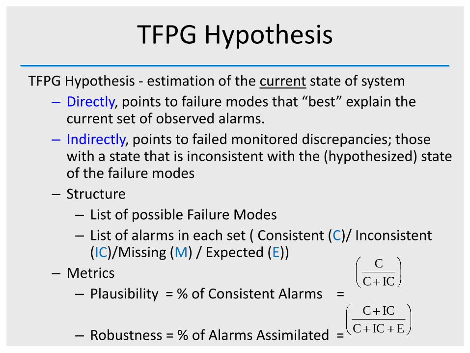
TFPG Hypothesis
TFPG Hypothesis - estimation of the current state of system
– Directly, points to failure modes that “best” explain the current set of observed alarms.
– Indirectly, points to failed monitored discrepancies; those with a state that is inconsistent with the (hypothesized) state of the failure modes
– Structure
– List of possible Failure Modes
– List of alarms in each set ( Consistent (C)/ Inconsistent (IC)/Missing (M) / Expected (E))
– Metrics
– Plausibility = % of Consistent Alarms =
– Robustness = % of Alarms Assimilated =
ICC
C
E ICC
ICC

TFPG and Distributed Software Systems
Using TFPG in large software systems pose two challenges:
• System components can operate in different modes, which leads to dynamic software dependency chains during runtime. This might require large-scale rewiring of models based on the concepts of modes supported by TFPG.
– This is true for a large-scientific computing clusters where a workflow management system can be executing a different job at a given time that might interact with other jobs on the system. This essentially changes the TFPG from time to time
– However, in a safety critical environment that uses an ARINC 653 compliant OS processes cannot be created dynamically. Effectively, this will lead to a smaller and mostly fixed cause and effect chain for the software system.
• Search space of a global TFPG model could be very large. Hence, we will need a component-based distributed reasoning approach where regional reasoners generate regional hypothesis, which could subsequently be improved by a global reasoner.
• A distributed and hierarchical TFPG reasoning scheme is currently being developed at Vanderbilt University to address this problem (Karsai et.al.). The TFPG model is split into a global model and multiple regional models where each region model accounts for a specific sub-system.
First International Workshop on Software Health Management, July 2009
13

Distributed TFPG: TFPG-D14
Downstream
Upstream
OR
AND
Disc1
Disc2
GLOBAL MODEL
O2OR
OR
AND
FM
FM
AM
AM
FMFM1
FM2
Disc1
Disc3
Disc2
FM3
AM2
AM1
I1
O1
Region 1
Region Model
O2
OR
OR
AND
FM
FM
AM
AM
I2
I3
I1
FM1
FM2
Disc1
Disc2
Disc3
AM2
AM1
O1
Region 3
Region Model
O2
OR
OR
AND
FM
FM
AM
AM
O1
O3
AM1
AM2
Disc3
Disc2
Disc1
FM1
FM2
I2
I1
Region 2
Region Model

Global Reasoner (GR) Initialization
Regional Reasoner(s) (RR)
Initialization
Failure Propagation across
Regional ModelsI/O Ports interaction
i
i TFPG Model
Distributed Reasoner – Model Input
O2OR
OR
AND
FM
FM
AM
AM
FMFM1
FM2
Disc1
Disc3
Disc2
FM3
AM2
AM1
I1
O1
Local1
Local Model
O2OR
OR
AND
FM
FM
AM
AM
O1
O3
AM1
AM2
Disc3
Disc2
Disc1
FM1
FM2
I2
I1
Local2
Region
O2
OR
OR
AND
FM
FM
AM
AM
I2
I3
I1
FM1
FM2
Disc1
Disc2
Disc3
AM2
AM1
O1
Region 3
RegionModel

Hypothesis Update
• Regional Reasoner– Update hypothesis for regional events or events across the
boundary through I/O Ports. – Communicate any boundary propagation to Global Reasoner
• Global Reasoner– Ensures transmission of failure effects across Regional
reasoners. – Assimilates Update from Regional Reasoners.
• Current Assumptions– No Network/Node Failure– Strict Communication constraint
• Regional TFPG do not communicate to each other

Work in progress• We are working towards developing software health management solution for
safety-critical systems that builds over Reflex and Healing architecture and Timed Fault Propagation Graphs.
• Software units abstracted as components.
– A component is a unit (containing potentially many objects). The component is parameterized, has state, it consumes resources, publishes and subscribes to events, provides interfaces and requires interfaces from other components
• Platform– ARINC-653 like RTOS emulated on Linux
• Reflex architecture mapped to ARINC-653 specification.
First International Workshop on Software Health Management, July 2009
17

Summary• Software is a complex engineering artifact.
– Typically abstracted as a timed discrete event model.
– We encapsulate software entities as components.
• Reflex and Healing Architecture– Reflexes are preprogrammed responses, implemented as time state
machine
– Healing involves a search over possible alternative configurations by solving a related constraint satisfaction / optimization problem
– We have implemented healing as a workflow replanning/rescheduling in scientific cluster computing.
– Can be mapped to an ARINC-653 compliant system.
• Timed Fault Propagation Graph– Restricting dynamic process creation simplifies the global TFPG model.
First International Workshop on Software Health Management, July 2009
18

Real-Time Reflex Engines
Scheduler maintains a fixed number of threads in a pool
• Verification is performed by mapping the reflex engine into a network of timed automatons
• Liveness, safety and bounded time response properties are then checked using UPPAAL
• Specific examples are presented in the chapter on mitigation in the dissertation
• A scheduler maps the input events in the buffer to the corresponding strategies.
– Sorts the event queue based on priority in the select state.
– Communicates the events via start and finished methods of the strategies.
23

Execution Tracking• Participants belonging to a workflow are mapped
onto machines and executed.• Participants interact with database through pre and
post run scripts• Pre-run: get participant information (binary
location), retrieve parameters from database, verification of input files, evaluate precondition
• Post-run: store provenance information in database (file locations and metadata), save participant execution status, evaluate postcondition
• Monitoring of vital health parameters on allocated nodes is enabled according to pre-specified rules. (invariants).
• Monitored sensor values for running participant are propagated upwards through the reflex and healing architecture.
• Example of conditions:• Precondition: dCache pool manager (pm) must be
available before the participant is started. H(pm)>0.• Postcondition: output file. Exists(file) = 1.
– Exists is an on-demand sensor to check existence of data products.
• Invariant: host is available. AG H(host) = 1.
24
Activity Sequence Diagram
Execution Engine

Workflow Recovery: WorkflowML Model Predictive Analysis
After some progression, a fault appears in job L4 and a predictive analysis is triggered to determine the progression of the workflow
Method to collapse the workflow and determine the final state which is achievable given the fault
• Modeling language which captures jobs, data stores, data dependency, and sequencing of operations• Jobs, synchronizers, and data stores are composed to form a workflow• Allows arbitrary synchronization of jobs without regard to data dependency• Jobs can be in one of 4 states: Initial, Running, Finished, and Faulty, and can be marked as being critical
25

Workflow Recovery: WorkflowML Model Predictive Analysis
After some progression, a fault appears in job L4 and a predictive analysis is triggered to determine the progression of the workflow
Method to collapse the workflow and determine the final state which is achievable given the fault
• Modeling language which captures jobs, data stores, data dependency, and sequencing of operations• Jobs, synchronizers, and data stores are composed to form a workflow• Allows arbitrary synchronization of jobs without regard to data dependency• Jobs can be in one of 4 states: Initial, Running, Finished, and Faulty, and can be marked as being critical
26
Nordstrom, S.; Dubey, A.; Keskinpala, T.; Datta, R.; Neema, S. & Bapty, T. (2007), Model Predictive Analysis for Autonomic Workflow Management in Large-scale Scientific Computing Environments, in '4th IEEE International Workshop on Engineering of Autonomic & Autonomous Systems (EASe)', pp. 37—42.