refinery expansion & petrochemical project, nayara energy ltd....
TRANSCRIPT

Page 1 of 78
For
ENVIRONMENTAL CLEARANCE
Of
Refinery Expansion & Petrochemical Project,
Nayara Energy Ltd.
At
Vadinar, Devbhumi Dwarka, Gujarat
Project Proponent:
M/s. Nayara Energy Ltd, Vadinar
May 2018
PRE-FEASIBILITY REPORT
Page 2 of 78
Contents
1. EXECUTIVE SUMMARY ......................................................................................................... 3
2. INTRODUCTION OF THE PROJECT ...................................................................................... 4
3. PROJECT DESCRIPTION ..................................................................................................... 13
4. SITE ANALYSIS: ................................................................................................................... 75
5. PROJECT PLANNING BRIEF: ............................................................................................... 77
6. REHABILITATION AND RESTTLEMENT (R&R) PLAN: ........................................................ 78
7. PROJECT SCHEDULE AND COST ESTIMATES .................................................................. 78
8. ANALYSIS OF PROPOSAL: .................................................................................................. 78

Page 3 of 78
1. EXECUTIVE SUMMARY
Nayara Energy Ltd, erstwhile Essar Oil Ltd, is a strong name worldwide in Oil & Gas Sector having
its registered office at Khambalia Post, PO Box 24, District- Devbhumi Dwarka, Gujarat-361305.
Its 20MMTPA Vadinar Refinery is second largest single location Refinery in India and is also
among the top 5 most complex refineries in the world. The company continues to strive for
excellence with its strengths, differentiated product mix, state-of-the-art technology, excellence in
execution and focus on sustainability.
Company is operating a 20MMTPA refinery complex at Vadinar, Devbhumi Dwarka, Gujarat. In
addition it has a strong retail network of 4,500 retail station catering to different part of Country.
The network is being expanded and 1,500 more retail stations are going to be added in near future.
India GDP growth rate is expected to be 8.2% over period of 2015 to 2040 as per Central Statistical
Organization, India. This strong demand growth outlook will require capacity addition of nearly 224
MMTPA refining capacity addition in India. This demand growth is also likely to create considerable
need of PP, HDPE, LLDPE and other petrochemical product’s capacity addition in India by 2025.
The company had an extensive plan of expanding the refinery capacity to 60MMTPA along with
Petrochemical Project. Owing to the business exigencies the plan could not be implemented as
planned. However, now the plan has been revisited and revised to expanding the Refinery capacity
to 46 MTPA along with Petrochemical Project. The existing “Environment Clearance” is expiring in
Sep’18 and hence this PFR is made for the purpose of new “Environment Clearance” for the
revised business plan.

Page 4 of 78
2. INTRODUCTION OF THE PROJECT
Nayara Energy Ltd presently operates the existing 20MMTPA Refinery and comprises of following
process units:
Crude Distillation Unit (CDU)/VDU (Vacuum Distillation Unit) /SGU (Saturated Gas Unit)
Naptha Hydro Treater (NHT)
Continuous Catalytic Reformer (CCR)
Fluidized Catalytic Cracking Unit (FCCU)
Diesel Hydro De Sulphurisation (DHDS)/ Diesel Hydrotreater (DHDT)
Hydrogen Manufacturing Unit (HMU)
Isomerisation Unit (ISOM)
Vacuum Gas Oil Mild Hydrotreaters (VGOMHC)
Delayed Coker Unit (DCU)
Amine Regeneration Unit (ARU)/ Sour Water Stripper (SWS)/ Sulphur Recovery Unit
(SRU)/ Sulphur Palletisation Unit (SPU)
It is now proposed to expand the Complex to 46 MMTPA Refining capacity along with
Petrochemical Project. The configuration study has been carried out with the crude basket with
following Crude mix having Blend API of 26.13 and 2.33 wt% sulphur:
Sr. No. Crude Blend wt% kTPA
1 Arab Heavy 7.7% 2,000
2 Arab Light 11.5% 3,000
3 Maya 23.1% 6,000
4 Doba 7.7% 2,000
5 Ratawi 26.9% 7,000
6 Cabinda 17.4% 4,524
7 Escalante 5.7% 1,476
Total 100% 26,000
Based on above consideration a comprehensive LP model was developed. The following is the list
of the proposed Refinery expansion/ Petrochemical Units

Page 5 of 78
Proposed Refinery Units:
Sr. No Units Capacity (KTPA)
1 Alkylation 1,600
2 Feed Preparation Unit (FPU) 6,000
3 Indmax FCC 4,500
4 Gasoline Desulphurisation (GDS-I) 2,577
5 ARU-III 1,100
6 Unsat LPG Treater Unit-III 2,050
7 Propylene Recovery Unit (PRU-I) 1,050
8 Poly Propylene (PP-I) 1,050
9 CDU/VDU-III 20,000
10 NHT-II 4,100
11 CCR-II 3,354
12 ISOM-II 1,910
13 DHDT-II 8,510
14 HMU-III/IV/V, kNm3/hr 447
15 HS FCCU#3 4,769
16 PRU-II 932
17 PP-II 1,000
18 LCO-X unit 1,767
19 DCU-II 7,250
20 Ebulated Bed RHCK 9,796
21 Hydrocracker 8,500
22 Solvent Deasphalting Unit (SDA) 2,562
23 ARU-IV/V 11,690
24 SWS-IV/V (P+NP) 5,571
25 SRU-IV 1,220
26 LPG Treater unit-II 539
27 Unsat LPG Treater Unit-IV 1,102
28 GDS-II 1,581
29 ATF HT 1,900
30 Ethanol 110

Page 6 of 78
Petrochemical Units:
Apart from Refinery units, Petrochemical units are also proposed and will mainly contain:
Cracker & associated Units
Aromatics
Polyester Intermediates
Polymer Units
Phenol Chain
Speciality Chemicals
Area Proposed Units Capacity
(KTPA)
PDH Propylene 1,000
Cracker & associated units
Ethylene 1,800
Butadine 180
Butene-1 50
MTBE/ETBE 150
Aromatic
Para Xylene (PX) 3,000
Linear Alkyl Benzene (LAB) 200
Styrene Monomer (SM) 500
Polyester Intermediates
Mono Ethylene Glycol (MEG)/ Di
Ethylene Glycol (DEG) 800
PTA 2,400
Polymer Units
PP 1,050
HDPE 500
LLDPE 550
LDPE/ EVA 200
Phenol Chain
Cumene 265
Phenol 200
Bisphenol-A 150
Polycarbonate 130
Speciality Chemicals
N-Butanol 200
i- Butanol 40
2 Ethyl Hexanol 120

Page 7 of 78
Neo Pentyl Glycol 40
Acrylic acid 250
Acrylates (Butyl, Ethyl, Methyl) 300
Super Absorbent Polymer (SAP) 100
Propylene Oxide (PO), Propylene
Glycol & Polyols 200
The Process details of the Project are dealt in Section 3.
Product Slate:
The Product slate of the proposed expansion project is listed below:
Refinery Expansion: Product slate for 46 MMTPA Refinery Complex:
Sr. No Product KTPA
1 LPG 785
2 Naphtha 63
3 Gasoline 10,663
4 SKO/ATF 624
5 Diesel 22,775
6 Sulphur 1,610
7 Petcoke 2,191
8 Bitumen 337
9 Ethanol 110
Petrochemical Project:
Sr. No Products Qty (KTPA)
1 Propylene 1000
2 Butadiene 180
3 MTBE/ETBE 150
4 Benzene 500

Page 8 of 78
6 PX 1400
7 PTA 2,400
8 LAB 200
9 PP 1,050
10 HDPE 500
11 LLDPE 550
12 LDPE/ EVA 200
13 MEG/DEG 800
14 SM 500
15 Phenol 200
16 Acetone 125
17 Bisphenol Acetone (BPA) 35
18 Polycarbonate 130
19 N-Butanol 50
20 i- Butanol 10
21 2 Ethyl Hexanol 120
22 Neo Pentyl Glycol (NPG) 40
23 Acrylic acid 10
24 Acrylates(Butyl, Methyl, Ethyl) 300
25 SAP 100
26 Propylene Oxide (PO)/PG/Polyols 200
Categorisation of the Project:
The proposed project is for enhancing the refining capacity of the existing refinery and also add
petrochemical products. The project falls under item no. 4 (a): “Petroleum Refining Industry” and
5 (C) “Petrochemical Complexes (industries based on processing of petroleum fractions and
natural gas and /or reforming to aromatics)” as per the EIA notification 2006 and its amendments.

Page 9 of 78
Need for the Project (demand/ supply gap) and its importance
Emerging Refining Deficit in India:
India has emerged as major refiner of the world having fourth largest refining capacity in the
world following USA, China and Russia. With 23 refineries with combine capacity of 247.6
MMTPA, India currently not only serving domestic demand of petroleum products of 195.7
MTPA (2017-18) but also supplying petroleum products to other Asian countries. India’s
exported 66 MMTPA (2016-17) petroleum products which is almost its total refining capacity
in 1998-1999. This reflects the India’s growing Refining Industry and its role in World’s trade
of Refined Products in a short span of time.
India GDP growth rate is expected to be 8.2% over period of 2015 to 2040 as per Central
Statistical Organization, India. Energy is central to achieving India’s development ambitions,
to support an expanding economy, to fuel the demand for greater mobility and to develop the
infrastructure to meet the needs of what is soon expected to be the world’s most populous
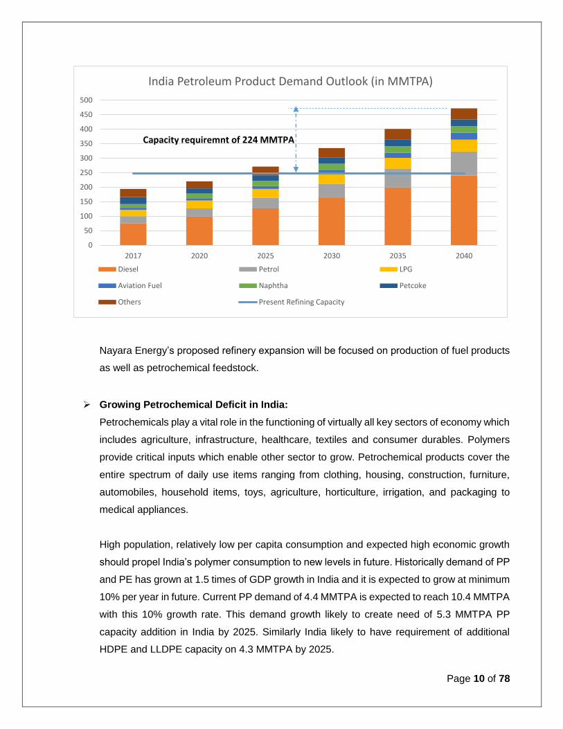
country. Based on strong GDP growth outlook, demand of petroleum products is expected
to grow to the level of 472 MMTPA as per demand projection of report of the working group
on enhancing refining capacity by 2040, published by Ministry of Petroleum and Natural Gas
India in January 2018. Demand of Diesel and Petrol is expected to grow at CAGR of 5.1%
and 5.6% till 2040.
This strong demand growth outlook will require capacity addition of nearly 224 MMTPA
refining capacity addition in India. In view of this emerging deficit in India, almost all Indian
refiners are looking to expand their production capacity. Proposed 26 MMTPA refinery
capacity addition of Nayara Energy is also aiming to primarily serve growing demand of
petroleum products in India.
Page 10 of 78
Nayara Energy’s proposed refinery expansion will be focused on production of fuel products
as well as petrochemical feedstock.
Growing Petrochemical Deficit in India:
Petrochemicals play a vital role in the functioning of virtually all key sectors of economy which
includes agriculture, infrastructure, healthcare, textiles and consumer durables. Polymers
provide critical inputs which enable other sector to grow. Petrochemical products cover the
entire spectrum of daily use items ranging from clothing, housing, construction, furniture,
automobiles, household items, toys, agriculture, horticulture, irrigation, and packaging to
medical appliances.
High population, relatively low per capita consumption and expected high economic growth
should propel India’s polymer consumption to new levels in future. Historically demand of PP
and PE has grown at 1.5 times of GDP growth in India and it is expected to grow at minimum
10% per year in future. Current PP demand of 4.4 MMTPA is expected to reach 10.4 MMTPA
with this 10% growth rate. This demand growth likely to create need of 5.3 MMTPA PP
capacity addition in India by 2025. Similarly India likely to have requirement of additional
HDPE and LLDPE capacity on 4.3 MMTPA by 2025.
0
50
100
150
200
250
300
350
400
450
500
2017 2020 2025 2030 2035 2040
India Petroleum Product Demand Outlook (in MMTPA)
Diesel Petrol LPG
Aviation Fuel Naphtha Petcoke
Others Present Refining Capacity
Capacity requiremnt of 224 MMTPA

Page 11 of 78
(Data in MMTPA)
Year 2016
-17
2017
-18
2018
-19
2019
-20
2020
-21
2021
-22
2022
-23
2023
-24
2024
-25
2025
-26
Polypropylene (PP)
PP India Demand 4.4 4.8 5.3 5.9 6.4 7.1 7.8 8.6 9.4 10.4
Present PP Capacity 5.1
Capacity addition
required
0.2 0.8 1.3 2.0 2.7 3.5 4.3 5.3
HDPE and LLDPE
HDPE and LLDPE India
Demand
3.9 4.3 4.8 5.2 5.8 6.3 7.0 7.7 8.4 9.3
Present HDPE and
LLDPE Capacity
5.0
Capacity addition
required
0.2 0.8 1.3 2.0 2.7 3.4 4.3
PTA Demand
PTA India Demand 5.5 5.8 6.2 6.6 6.9 7.4 7.8 8.3 8.8 9.3
Present PTA Capacity 7.5
Capacity addition
required
0.3 0.8 1.3 1.8
Paraxylene (PX)
PX Demand 3.7 3.9 4.1 4.4 4.7 4.9 5.2 5.5 5.9 6.2
Present PX Capacity 5.6
Capacity addition
required
0.3 0.6

Page 12 of 78
Growing polyester and PET demand in India will absorb current surplus in PX and PTA in
India. By 2025, PTA and PX likely to have deficit of 1.8 MMTPA and 0.6 MMTPA respectively.
In view of this market scenario, proposed project plan of Nayara Energy has emphasis on
production PP, HDPE, LLDPE, PX and PTA for serving growing market in India.
Employment Generation due to the Project:
The proposed Expansion project will provide direct/indirect employment to about 12000-15000
persons during the peak construction phase and about 2000-3000 persons during operation.

Page 13 of 78
3. PROJECT DESCRIPTION
Project information: The expansion Project aims to expand the Crude handling capacity of the Complex to 46 MMTPA
from present 20 MMTPA. The downstream Refinery units shall produce range of products
including:
Liquefied petroleum gas (LPG)
Naptha
Gasoline
Jet Fuel / Kerosene
Diesel
Bitumen
Sulphur and coke
Ethanol etc
Apart from this “Expansion Project” includes Petrochemical Complex as well, which shall be
integrated with the Refinery units to enhance the GRM.
The Proposed Petrochemical complex shall consists of following:
Cracker & associated Units
Aromatics
Polyester Intermediates
Polymer Units
Phenol Chain
Speciality Chemicals
The Expansion Project will be within the existing Refinery / Petrochemical premises and shall be
interlinked with the existing units.

Page 14 of 78
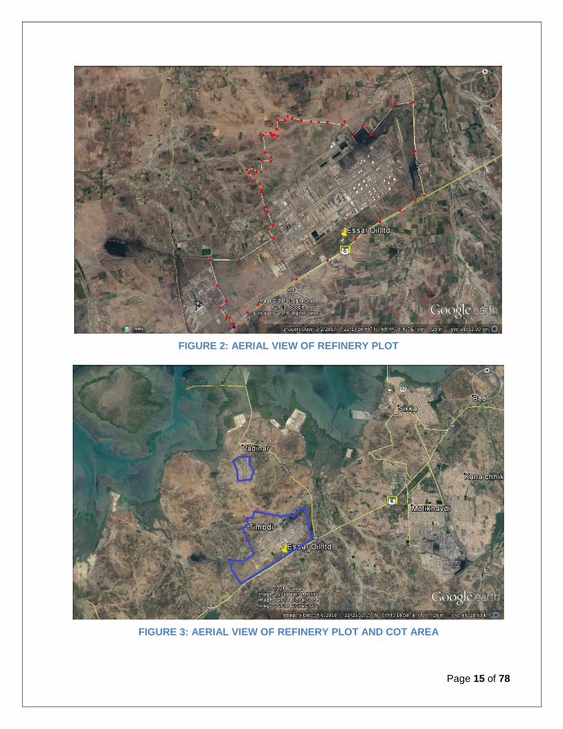
Project Location: The expansion units will come up at existing Refinery Complex situated at Vadinar, District. -
Devbhumi Dwarka.,Gujarat.
FIGURE 1: LOCATION OF PROJECT
Page 15 of 78
FIGURE 2: AERIAL VIEW OF REFINERY PLOT
FIGURE 3: AERIAL VIEW OF REFINERY PLOT AND COT AREA

Page 16 of 78
Process Details: Atmospheric and Vacuum Distillation Units:
Atmospheric distillation involves the physical separation of hydrocarbon components into
fractions or intermediates of a specified boiling temperature range by distillation and steam
stripping. The major processing equipment items include the heat exchanger preheat train,
desalter, direct-fired furnace, atmospheric fractionator, and side stream product strippers.
Crude is preheated in the heat exchanger train by recovering process heat. This crude is sent to
a desalter to remove salts and sediments. The desalted crude is further heated in a preheat heat
exchanger train and is then charged to a direct-fired furnace, where additional heat is supplied
to achieve partial vaporization of the crude petroleum. Both the liquid and vaporized portions
are charged to the atmospheric fractionator.
The crude charge is separated into several petroleum fractions within the atmospheric
fractionator. A naphtha and lighter stream is taken from the tower overhead, where it is
condensed. The non-condensable light ends are treated and/or recovered in Saturated Gas Unit.
Several liquid side stream fractions are withdrawn from the fractionator at different elevations
within the tower. These fractions are charged to the side stream product strippers, where lighter
hydrocarbons are stripped from these fractions and returned to the fractionation tower. The
stripping medium is either steam or reboiler vapours. In addition to the side stream strippers, the
atmospheric fractionator has a bottoms stripping zone whereby lighter hydrocarbons are steam
stripped from the residual product.
The fractions withdrawn from the atmospheric tower are progressively heavier because they are
taken from the fractionator at successively lower points. The end point of the heaviest side
stream product closely corresponds to the crude’s temperature as charged to the fractionator.
Fractionator bottoms (topped crude), is the heaviest petroleum fraction and is the charge to the
vacuum distillation unit.
The atmospheric tower produces low, intermediate, and high boiling range products. Low boiling
range products are fuel gas and light naphtha. Naphtha is further processed to improve octane
rating and reduce sulphur content. Kerosene may be chemically sweetened or hydrogen treated
and sold directly or sent to blending as the case may be. Distillates may be sold as jet fuel or
diesel fuel oil, hydrogen treated, catalytically cracked, or blended. Gas oil is catalytically cracked.
The high boiling stream—topped crude—is the feed to the vacuum distillation process.

Page 17 of 78
Figure - Schematic flow diagram of a typical crude oil distillation unit as used in petroleum crude oil refineries
Vacuum distillation separates the residue from the atmospheric crude still into a heavy residual oil and
one or more heavy gas oil streams, thereby avoiding the extremely high temperatures necessary to
produce these heavy distillates by atmospheric fractionation. Vacuum distillation units operate by
either steam ejectors or mechanical vacuum pumps. These vacuum systems are designed to remove
the non-condensable hydrocarbon vapors produced by thermal cracking of the reduced crude charge.
Vacuum distillation is accomplished in one or (occasionally) two stages. Reduced crude is heated
in a direct-fired furnace and charged to the vacuum fractionator. The intermediate products (light
and heavy virgin gas oil or VGO) from the vacuum distillation process are sent to the catalytic
cracker or hydrotreater or hydrocracker.

Page 18 of 78
Figure – A typical Vacuum Distillation tower and its cuts
The primary fractionation would be traditional atmospheric and vacuum fractionation designed
for sour crudes.
Hydrotreating Units – NHT, DHDT, ATFHT and VGO HDT
The hydrotreating process, removes objectionable materials from petroleum distillates by selectively
reacting these materials with hydrogen in a catalyst bed at elevated temperature. These objectionable
materials include sulfur, and nitrogen in virgin streams and sulfur, nitrogen and olefins in cracked
stocks. Some units are also designed to saturate aromatics into cycloparaffins to improve key product
properties such as diesel cetane number.
Naphtha, kerosene, diesel, vacuum gas oil and even vacuum residue are hydrotreated, depending
on the requirements. Intermediate streams from cracking processes (for example coker gas oil or
FCCU light cycle oil) may also require hydrotreating. The chemistry behind the hydrotreating process
can be divided into a number of reaction categories: hydrodesulphurization, hydrodenitrification,

Page 19 of 78
saturation of olefins and saturation of aromatics. For each of these reactions, hydrogen is consumed.
Hydrogen requirements increase with higher boiling feeds and with higher concentrations of
intermediate fractions in the total unit feedstock.
For the heavier fractions such as VGO and residue, the units are also designed to remove low levels
of metals from the feed. The metals to be removed include nickel, vanadium and silicon. These
elements lower catalyst activity by clogging the active surface of the catalyst. In units with higher feed
metals, sacrificial catalyst with very low activity is sometimes used in the front reactors. The catalysts
used in hydrotreaters are typically a combination of Cobalt/Molybdenum and Nickel/Molybdenum.
In a typical hydrotreater, the feed is heat exchanged with the reactor effluent, mixed with recycle
hydrogen and then heated to reaction temperature in a fired heater. The combined feed then flows
through the reactor, which contains the catalyst that will accelerate the reaction. The reactor effluent
is cooled in exchange with the feed and then in a series of coolers before being separated in a vapor-
liquid separator. The vapor portion is recompressed, combined with fresh hydrogen, and returned to
the reactor feed. The liquid portion is fed to a fractionator, where it is stripped of light ends, hydrogen
sulfide and ammonia. Reaction products such as naphtha and diesel, which may be produced as
byproducts of hydrotreating heavy feedstocks, are also separated.
Schematic diagram of a typical hydrotreating unit is shown below.
Figure – Typical Hydrotreating Unit Schematic Diagram

Page 20 of 78
Fluidized Catalytic Cracking Unit (FCCU)
FCCU is a multi-component catalyst system with circulating fluid bed system with reactor-
regenerator configuration. Typical feedstock to a FCC unit consists of vacuum gas oil or
atmospheric gas oil but may include other heavy streams also. While FCC units have traditionally
been operated to maximize gasoline or distillate production, interest in maximizing light olefins,
particularly propylene, has gained attraction in recent decades. FCC catalyst formulation and
process technology improvements now give refiners the flexibility to boost propylene yields from
traditional levels of 4–6 wt% to beyond 20 wt%.
FCC Process
In its simplest form, the process consists of a reactor, a catalyst regenerator, and product
separation, as shown in figure below. Catalyst circulation is continuous, at very large mass flow
rates. For this reason, the reactor and regenerator are usually discussed as one section. The
product separation is usually divided into its low and high pressure components, i.e. the main
column section, and the gas concentration and recovery section.
Reactor-Regenerator
This is the heart of the process, where the heavy feed is cracked. The reaction products range
from oil which is heavier than the charge to a light fuel gas. The catalyst is continuously
regenerated by burning off the coke deposited during the cracking reaction. This provides a large
measure of the heat required for the process.
Regenerator Reactor
CatalystTransfer
LinesProduct
Separation
Raw OilAir
Flue Gas
Products
Page 21 of 78
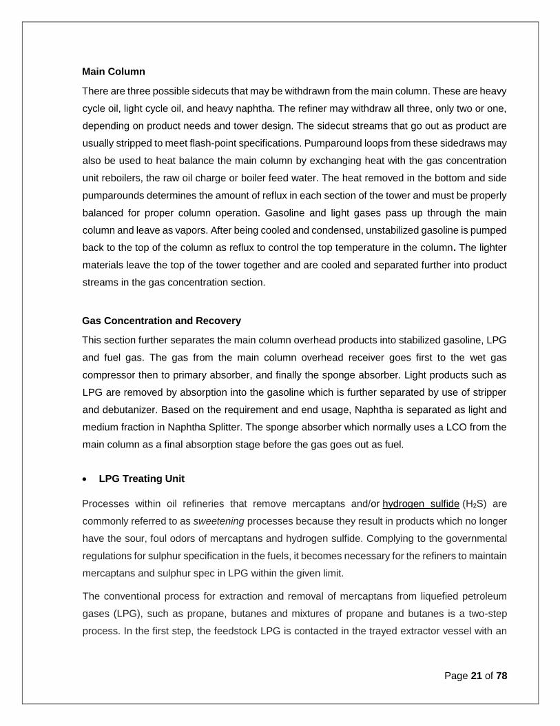
Main Column
There are three possible sidecuts that may be withdrawn from the main column. These are heavy
cycle oil, light cycle oil, and heavy naphtha. The refiner may withdraw all three, only two or one,
depending on product needs and tower design. The sidecut streams that go out as product are
usually stripped to meet flash-point specifications. Pumparound loops from these sidedraws may
also be used to heat balance the main column by exchanging heat with the gas concentration
unit reboilers, the raw oil charge or boiler feed water. The heat removed in the bottom and side
pumparounds determines the amount of reflux in each section of the tower and must be properly
balanced for proper column operation. Gasoline and light gases pass up through the main
column and leave as vapors. After being cooled and condensed, unstabilized gasoline is pumped
back to the top of the column as reflux to control the top temperature in the column. The lighter
materials leave the top of the tower together and are cooled and separated further into product
streams in the gas concentration section.
Gas Concentration and Recovery
This section further separates the main column overhead products into stabilized gasoline, LPG
and fuel gas. The gas from the main column overhead receiver goes first to the wet gas
compressor then to primary absorber, and finally the sponge absorber. Light products such as
LPG are removed by absorption into the gasoline which is further separated by use of stripper
and debutanizer. Based on the requirement and end usage, Naphtha is separated as light and
medium fraction in Naphtha Splitter. The sponge absorber which normally uses a LCO from the
main column as a final absorption stage before the gas goes out as fuel.
LPG Treating Unit
Processes within oil refineries that remove mercaptans and/or hydrogen sulfide (H2S) are
commonly referred to as sweetening processes because they result in products which no longer
have the sour, foul odors of mercaptans and hydrogen sulfide. Complying to the governmental
regulations for sulphur specification in the fuels, it becomes necessary for the refiners to maintain
mercaptans and sulphur spec in LPG within the given limit.
The conventional process for extraction and removal of mercaptans from liquefied petroleum
gases (LPG), such as propane, butanes and mixtures of propane and butanes is a two-step
process. In the first step, the feedstock LPG is contacted in the trayed extractor vessel with an

Page 22 of 78
aqueous caustic solution containing liquid catalyst. The caustic solution reacts with mercaptans
and extracts them. The reaction that takes place in the extractor is:
2RSH + 2 NaOH → 2NaSR + 2 H2O
In the above reaction, RSH is a mercaptan and R signifies an organic group such as a methyl,
ethyl, propyl or other group. For example, the ethyl mercaptan has the formula C2H5SH.
The second step is referred to as regeneration and it involves heating and oxidizing of the caustic
solution leaving the extractor. The oxidations results in converting the extracted mercaptans to
organic disulfides (RSSR) which are liquids that are water-insoluble and are then separated and
decanted from the aqueous caustic solution. The reaction that takes place in the regeneration
step is:
4NaSR + O2 + 2H2O → 2RSSR + 4NaOH
After decantation of the disulfides, the regenerated "lean" caustic solution is recirculated back to
the top of the extractor to continue extracting mercaptans.
The net overall reaction covering the extraction and the regeneration step may be expressed as:
4 RSH + O2 → 2RSSR + 2H2O
The feedstock entering the extractor must be free of any H2S. Otherwise, any H2S entering the
extractor would react with the circulating caustic solution and interfere with the merox reactions.
Therefore, the feedstock is first "prewashed" by flowing through a batch of aqueous caustic to
remove any H2S. The reaction that takes place in the prewash vessel is:
H2S + NaOH → NaSH + H2O
The batch of caustic solution in the prewash vessel is periodically discarded as and replaced by
fresh caustic as needed.
The flow diagram below depicts the equipment and the flow paths involved in the process.
LPG feedstock enters the prewash vessel and flows upward through a batch of caustic which
removes any H2S that may be present in the feedstock. The coalescer at the top of the
prewash vessel prevents caustic from being entrained and carried out of the vessel.
The feedstock then enters the mercaptan extractor and flows upward through the contact trays
where the LPG intimately contacts the downflowing caustic that extracts the mercaptans from

Page 23 of 78
the LPG. The sweetened LPG exits the tower and flows through: a caustic settler vessel to
remove any entrained caustic, a water wash vessel to further remove any residual entrained
caustic and a vessel containing a bed of rock salt to remove any entrained water. The dry
sweetened LPG exits the unit.
The caustic solution leaving the bottom of the mercaptan extractor ("rich" caustic) flows through
a control valve which maintains the extractor pressure needed to keep the LPG liquified. It is
then injected with proprietary liquid catalyst (on an as needed basis), flows through a steam-
heated heat exchanger and is injected with compressed air before entering the oxidizer vessel
where the extracted mercaptans are converted to disulfides. The oxidizer vessel has a packed
bed to keep the aqueous caustic and the water-insoluble disulfide well contacted and well mixed.
The caustic-disulfide mixture then flows into the separator vessel where it is allowed to form a
lower layer of "lean" caustic and an upper layer of disulfides. The vertical section of the separator
is for the disengagement and venting of excess air and includes a raschig ring section to prevent
entrainment of any disulfides in the vented air. The disulfides are withdrawn from the separator
and routed to fuel storage or to a hydrotreater unit. The regenerated lean caustic is then pumped
back to the top of the extractor for reuse.

Page 24 of 78
Propylene Recovery Unit (PRU)
The general function of this unit is to separate polymer grade propylene of 99.5% wt purity from
Saturated and Cracked LPG Streams originating from the refinery/FCC and Delayed Coker unit (ex-
Merox). Cracked LPG Stream (ex-Merox) is basically a mixture of Propane, Propylene, C2s and C4s
Sections of PRU:
Depropanizer
Deethanizer
C3 Splitter
Propylene Purification
Adsorbent Regeneration Section
Condensate Recovery Section
Depropanizer Section

Page 25 of 78
The Cracked LPG (ex-Merox) is fed to the Depropanizer Column via Depropanizer feed pump
connected to the intermediate feed surge drums. This feed is preheated by a feed pre-heater which
exchanges heat with Depropanizer bottom product. LP Steam is used to heat the column reboiler.
The vapors from the column top are condensed by condenser using cooling media.
Depropanizer column bottom product (C4s+) is diverted to Straight run LPG storage header based
on the Depropanizer column bottom level control. In case bottom product is off spec on desired purity
then it is diverted back to Cracked LPG storage. The overhead product containing <0.8 wt% total C4s
is fed forward to Deethanizer column via pumps.
Deethanizer Section
The Depropanizer column overhead distillate product is sent as feed to Deethanizer column under
flow control cascaded with reflux drum level. The light components namely C2s, H2S, CO, CO2, etc.
are separated from C3+ hydrocarbon stream in the Deethanizer column overhead. The above light
components are purged through to the fuel gas header under pressure control. C3+ hydrocarbon
stream is withdrawn as bottom product from the column.
The reflux drum is provided with a boot leg for draining any traces of water separated from the
hydrocarbons. Deethanizer Column bottom product containing primarily C3s is sent on level control
as feed to C3 splitter column for further separation.
C3 Splitter Section
The C3+ Splitter is generally built in two columns as the height exceeds the maximum permissible for
a single column. C3+ (Propane-Propylene) Splitter operates with the help of an integrated heat pump
system. The heat pump system consists of a compressor which is heat integrated with the column
reboiler and a trim condenser. Vapors from the column overhead are knocked off any traces of liquid
in the compressor suction drum before going to compressor suction. Hot vapor from compressor
discharge is desuperheated in the exchanger and then supplied as the reboiling media to the reboilers.
Propylene product from the product draw off vessel is sent on level control to Propylene purification
section for removal of impurities COS, H2S, N2, Oxygenates and Moisture in order to conform to
Polymer Grade Propylene Specs.
Propylene Purification Section

Page 26 of 78
COS, H2S, Arsine, N2, Oxygenates and moisture impurities removal is undertaken by utilizing
Adsorbent Beds. These adsorbent beds are filled with proprietary mixed bed adsorbents to effectively
remove impurities and achieve Polymer grade Propylene Specs.
The Outlet Polymer grade propylene product purity from the beds is monitored using an online
analyzer. The adsorbent beds are alternatively regenerated using hot Nitrogen. The final polymer
grade propylene product is sent to Mounded Bullets for storage.
Schematic of the Propylene Recovery Unit is given below:
Polypropylene Unit
Modern PP processes are of these two basic types-
The bulk phase processes are typically conducted in a loop reactor, though variants in a stirred tank
reactor also exist. The major advantage of this process is the high thermal conductivity of the liquid
propylene, which ensures an even temperature profile within the reactor and thus stability. However,
if block co-polymers are to be made, the second reactor must be a gas phase reactor since fouling
occurs in propylene slurry. Similarly, if random co-polymers are made, the ethylene content is limited
by the solubility of the polymer in the liquid propylene diluent.
The gas phase processes consists of two main types: fluidized bed processes and stirred bed
processes or horizontal stirred bed process. The advantages of gas phase processes are process
simplicity (especially for co-polymers, since both reactors are gas phase), less fouling in co-polymer
production (since no diluents is used) and a lower inventory of propylene in the plant.
There are 3 major types of polypropylene:

Page 27 of 78
1. Homopolymers — polymers containing only propylene
2. Random co-polymers — polymers of propylene with other monomers, typically ethylene but also
in some cases butene-1, in which these other monomers are randomly dispersed along the
polymer chain
3. Block or impact co-polymers — polymers of propylene with ethylene in which the polymer chain
consists of distinct blocks of propylene Homopolymers and propylene-ethylene co-polymers.
Polypropylene is an extremely versatile and relatively inexpensive polymer that can be used in all
major resin fabrication processes; blow molding, injection, fibers and film.
A typical Schematic of a propylene polymerization plant is given below:
Alkylation
Alkylation is the process of producing gasoline range material light olefins (primarily propylene
and butylene) with isobutane in the presence of a highly acidic catalyst, either sulfuric acid or
hydrofluoric acid. The product (alkylate) contains a mixture of high-octane, branched-chain
paraffinic hydrocarbons. Refinery gases produced from different units are collected and sent to
the gas plant. Olefins and isobutanes are separated and used as a feed to the alkylation plant to
produce gasoline which can be sent to the gasoline pool.
Alkylation is catalyzed by a strong acid, either sulphuric (H2SO4) or hydrofluoric (HF). In the
absence of catalysts, alkylation between isobutene and olefin must be run under severe
conditions. In the presence of an acid catalyst, the reaction temperature and pressure will be
quite low. The major difference in using either acid is that isobutane is quite insoluble in H2SO4
but reasonably soluble in HF. This requires the use of high isobutane/olefin ratios to compensate
for low solubility in H2SO4. Furthermore, the reaction must occur at low temperature. The
alkylation process consists of running the hydrocarbons in liquid form and at low temperature
Monomer recycle Polypropylene- BFD
Catalyst/Co-catalyst
Modifier
Propylene
Ethylene
PP StorageExtrusion & Pelletising
Ploy-merization
Reactor
Powder TransferSection
PowderDe-
Activation

Page 28 of 78
and with a high isobutane (iC4) to olefin (such as C4) ratio. The reaction products are sent to an
acid settler where the acid is recycled back to the reactor. Products are then separated into
gaseous LPG propane and n-butane and the desired product of alkylate.
Simple block diagram of the process is shown below:
LCO-X unit
The LCO-X process, utilizes elements of hydrocracking and aromatics processing technologies
to get the most value from a major byproduct of your FCC. The high level of aromatics present
in LCO makes it suitable for cost effective conversion to benzene, toluene and xylenes, which
are high-value aromatics feedstocks.

Page 29 of 78
Figure – Schematic Diagram of LCO-X process
Delayed Coker Unit
The delayed coking process is a thermal cracking process for upgrading heavy petroleum
residues into lighter gaseous and liquid products and solid coke (petcoke). Cokers are very
flexible and can easily process almost any heavy crude.
The feed streams to the coker unit will include vacuum residue from the vacuum tower and slurry
from the HP FCC unit. The products from the unit will be fuel gas, mixed C3/C4 LPG, coker
naphtha, two coker gas oil cuts and petcoke. The process also makes considerable sour water
and process water that must be treated.
A delayed coker is completely a thermal process — no catalysts are used. In the process, some
molecules are cracked to produce the lighter products while others (mainly the polynuclear
aromatics) condense, producing the petroleum coke. Compared to other refinery units, delayed
cokers are relatively complex and have several distinct sections. These include:
Coker feed system, furnaces, coke drums and primary fractionation - Here, the feed is
pumped into the furnace and heated and oil begins to thermally decompose. As the material
enters the coke drum, the lighter products formed by thermal cracking in the heaters separate
from the heavy residual carbon. These lighter compounds boil out of the drum and are sent
to the fractionator to be separated into boiling range fractions. Over a period of 12 to 24
hours, the coke drums slowly fill with this residual material, which is known as petroleum

Page 30 of 78
coke. Once a drum is full, the coke is cut out using high-pressure water jets in a process
known as decoking. A delayed coker is designed so that there is always one coke drum set
available to be filled while one or more others are being decoked. This design allows the
heaters to operate continuously.
The Vapor recovery section — The coking process forms gases, which are the overhead
product from the fractionators. These gases include butane and lighter hydrocarbons and
hydrogen sulfide. In this section, the gases are compressed then send to a normal
absorber/stripper system. Liquid LPGs are separated from the gases. Hydrogen sulfide is
removed using amine and sent to the sulfur plant.
Coke drum steamout/blowdown system — As a part of the decoking process, a drum that is
full of hot coke is cooled using water in a circulating loop. This, of course, makes large
amounts of steam, which is condensed and recirculated. Some amount of oil is also carried
over and separated.
Decoking equipment — The hard cooled coke must be cut from the drums using high
pressure water. This requires special pumps and cutting equipment. For safety reasons and
speed, essentially all new cokers have automatic deheading and coke cutting equipment.
Coke handling — The cut coke is spilled onto a cement pad or pit. Smaller cokers sometimes
use front end loaders to pick up the coke and put it into trucks, railcars or barges for
movement.

Page 31 of 78
Figure - Schematic diagram of a Delayed Coker unit
Cokers are cyclic units with drums being taken out of service to cut the delayed coke. Smaller
cokers have two drum with one operating while the other is being decoked. As units get larger,
it is necessary to design with parallel sets of drums since the maximum drum diameter is limited
by the ability to cut the coke. As coke drum diameter increases, the pressure of the water used
to cut the coke must increase to guarantee that all of the coke is cut from the drum wall. The
cutting water is pumped by a specialized high pressure pump.
Hydrocracking
A hydrocracker looks very similar to a hydrotreater but, as a result of different catalysts and
operating conditions, is able to convert the feed into lighter products. At the time when
hydrocracking takes place, sulfur, nitrogen and oxygen are completely removed and olefins are

Page 32 of 78
saturated so that the products are a mixture of essentially pure paraffins, naphthenes and
aromatics. The primary reactions of Hydrocracking are – Desulphurization, Demetallization,
Denitrification, Olefin Saturation and Aromatic Saturation. Here, first sulfur and nitrogen is
removed from the feed, and then the purified feed is sent to the cracking section. This is
necessary since the metals that catalyze hydrocracking are poisoned by sulfur and nitrogen.
Hydrocracking produces unusually high ratio of i-paraffins to n-paraffins in the naphtha cut. It
produces middle distillates having excellent burning qualities and produces diesel fuel having
very low sulphur content, which doesn’t require any other further processing. Hydrocrackers
operate at about 3000 psig.
While the process flow diagram of a hydrocracker looks very similar to that of a high pressure
hydrotreater in the reaction section, the fractionation section of a hydrocracker is more complex
since there is a wider distribution of products.
There are 3 types of Hydrocarbon configurations –
1) Single Stage, Once Through (SSOT) Unit:
Page 33 of 78
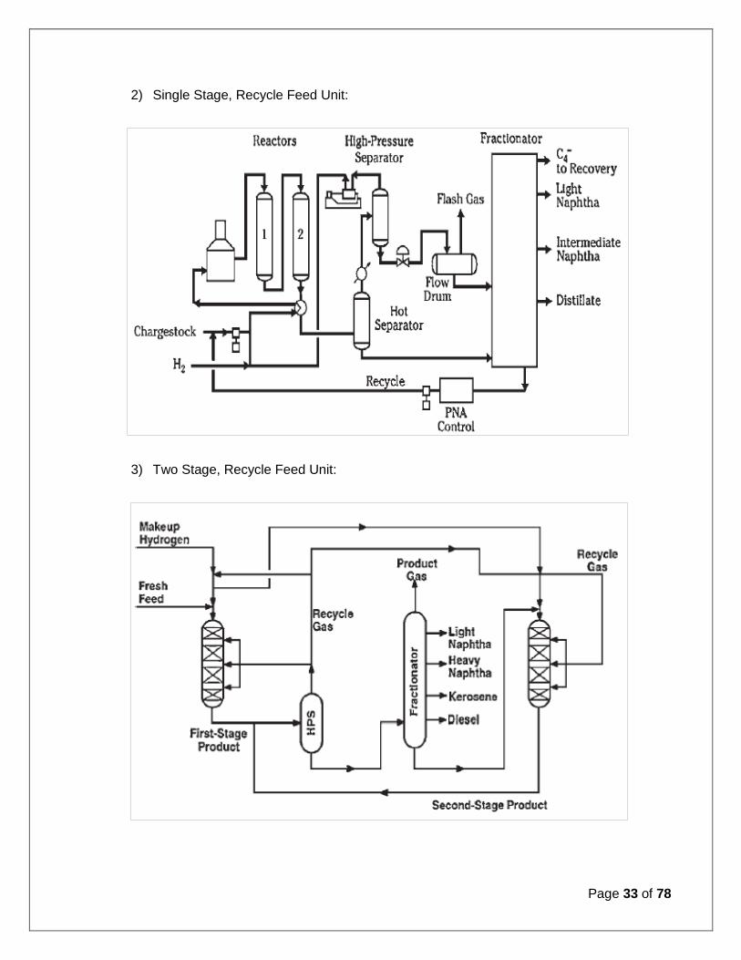
2) Single Stage, Recycle Feed Unit:
3) Two Stage, Recycle Feed Unit:
Page 34 of 78
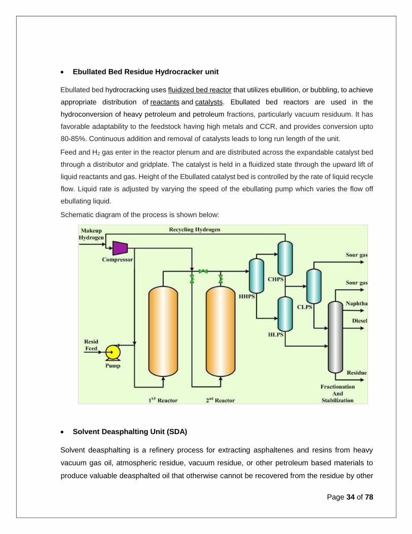
Ebullated Bed Residue Hydrocracker unit
Ebullated bed hydrocracking uses fluidized bed reactor that utilizes ebullition, or bubbling, to achieve
appropriate distribution of reactants and catalysts. Ebullated bed reactors are used in the
hydroconversion of heavy petroleum and petroleum fractions, particularly vacuum residuum. It has
favorable adaptability to the feedstock having high metals and CCR, and provides conversion upto
80-85%. Continuous addition and removal of catalysts leads to long run length of the unit.
Feed and H2 gas enter in the reactor plenum and are distributed across the expandable catalyst bed
through a distributor and gridplate. The catalyst is held in a fluidized state through the upward lift of
liquid reactants and gas. Height of the Ebullated catalyst bed is controlled by the rate of liquid recycle
flow. Liquid rate is adjusted by varying the speed of the ebullating pump which varies the flow off
ebullating liquid.
Schematic diagram of the process is shown below:
Solvent Deasphalting Unit (SDA)
Solvent deasphalting is a refinery process for extracting asphaltenes and resins from heavy
vacuum gas oil, atmospheric residue, vacuum residue, or other petroleum based materials to
produce valuable deasphalted oil that otherwise cannot be recovered from the residue by other

Page 35 of 78
refinery processes. The deasphalted oil (DAO) can be used to make lubricants or can instead
be used as feed to the fluid catalytic cracker, hydrocracker, or other refinery units.
The process consists of contacting the feedstock with a solvent in a counter-current extractor at
temperatures and pressures to precipitate the asphaltene fractions which are not soluble in the
solvent. Solvent selection and operating conditions are dictated by the desired product yields
and qualities.
Schematic diagram of a typical solvent deasphalting unit is shown below:
Isomerization Unit
The function of this unit is to increase the octane value of light naphtha, such that it can be
blended into gasoline. The process is specifically designed for catalytic isomerization of light
naphtha — reacting linear paraffins, which have very low octane values to form branched
paraffins with much higher octane values. The reactions take place in a hydrogen atmosphere,
over a fixed bed of catalyst, and at operating conditions that promote isomerization and minimize
hydrocracking.
Page 36 of 78
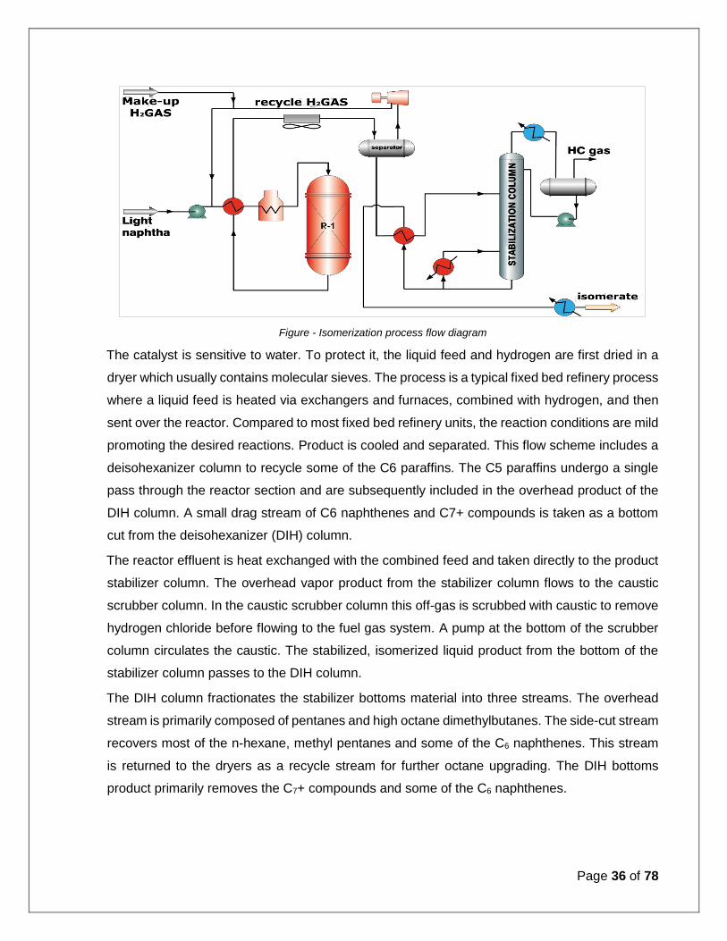
Figure - Isomerization process flow diagram
The catalyst is sensitive to water. To protect it, the liquid feed and hydrogen are first dried in a
dryer which usually contains molecular sieves. The process is a typical fixed bed refinery process
where a liquid feed is heated via exchangers and furnaces, combined with hydrogen, and then
sent over the reactor. Compared to most fixed bed refinery units, the reaction conditions are mild
promoting the desired reactions. Product is cooled and separated. This flow scheme includes a
deisohexanizer column to recycle some of the C6 paraffins. The C5 paraffins undergo a single
pass through the reactor section and are subsequently included in the overhead product of the
DIH column. A small drag stream of C6 naphthenes and C7+ compounds is taken as a bottom
cut from the deisohexanizer (DIH) column.
The reactor effluent is heat exchanged with the combined feed and taken directly to the product
stabilizer column. The overhead vapor product from the stabilizer column flows to the caustic
scrubber column. In the caustic scrubber column this off-gas is scrubbed with caustic to remove
hydrogen chloride before flowing to the fuel gas system. A pump at the bottom of the scrubber
column circulates the caustic. The stabilized, isomerized liquid product from the bottom of the
stabilizer column passes to the DIH column.
The DIH column fractionates the stabilizer bottoms material into three streams. The overhead
stream is primarily composed of pentanes and high octane dimethylbutanes. The side-cut stream
recovers most of the n-hexane, methyl pentanes and some of the C6 naphthenes. This stream
is returned to the dryers as a recycle stream for further octane upgrading. The DIH bottoms
product primarily removes the C7+ compounds and some of the C6 naphthenes.

Page 37 of 78
The net overhead liquid stream from the DIH can be taken as a product to be blended into the
gasoline pool. The DIH bottoms stream can be combined with the overhead product or it can be
sent to a reforming unit depending on the processing objectives.
Heat input to the DIH column is by a steam reboiler, generally serviced by low pressure steam.
The reboiler heat input is adjusted to generate adequate reflux in the column. The overhead
vapor from the column is totally condensed in an air fin exchanger. A hot vapor bypass is used
to control the overhead pressure without product vent losses. Isomerization technology is widely
practiced.
Organic chloride promoter is added continuously with the feed and is converted to hydrogen
chloride in the reactor. It leaves the unit by way of the stabilizer gas. The quantity of stabilizer
gas is small, due to the selective nature of the catalyst that permits very little hydrocracking of
the light naphtha charge to take place. The stabilizer gas contains the excess hydrogen required
for plant control and the C1-C3 hydrocarbons introduced by way of the make-up hydrogen. The
stabilizer off gas is scrubbed for hydrogen chloride removal before entering the refinery fuel gas
system.
Figure - Isomerization process flow diagram with pentane and hexane recycle
When the benzene specifications in gasoline are tight, Isomerization unit may also be used to
control benzene. In such a design, the feedstock is cut slightly heavier so benzene is sent to the
unit
Page 38 of 78
Catalytic Reforming
Configuration includes a catalytic reformer to convert naphtha to a high octane gasoline blend
stock called reformate. Basically, a reformer converts long-chained paraffin and naphthene
molecules, which generally have low octane, into aromatics such as benzene, toluene and
xylenes, which have high octane. Since benzene content is limited in gasoline, the reformer
feedstock is normally tailored by distillation to minimize benzene yield unless petrochemical
benzene is desired.
One of the side reactions of reforming is the formation of a small amount of coke – essentially
carbon on the catalyst. Almost all reformers have a continuous regeneration system. This allows
the refiner to operate the unit for several years without shutting down.
In the process, desulfurized naphtha (S<1 ppm) is combined with hydrogen and sent into a large
single pass countercurrent heat exchanger where it is heated. It is then sent into the feed heater
where it is further heated, depending on the required severity and the quality of the feedstock.
The vapor enters the first reactor where it undergoes rapid dehydrogenation of naphthenes to
produce aromatics. This reaction is endothermic and the temperature drops to the point at which
the reaction rates are slowed.
The reactor effluent goes into a reheater where it is again heated and sent to the second reactor.
Any remaining naphthenes are dehydrogenated and paraffins begin to undergo cyclization to
naphthenes, which are also dehydrogenated. The temperature again drops, but the drop is not
as much as in the first reactor. The material is again reheated and sent to a third reactor where
the prime reactions are continued. In the tail reactor, hydrocracking of the paraffin molecules,
which is an undesirable reaction begins to occur. Reformers have three to four reactors,
depending on the feedstock and process requirements. The final reactor effluent is cooled across
the feed/effluent exchanger, then via air and water. Hydrogen and the produced light gases are
separated from the liquids, usually in a single flash drum. The liquid product is pumped to a
stabilizer tower where butanes and lighter hydrocarbons are separated as a small overhead
stream. The gas stream from the flash drum is separated into recycle gas and net hydrogen
production. Hydrogen purity depends on a number of variables, but is normally in the range of
80-85 vol%. The unit may include additional equipment to further purify the hydrogen.
In the continuous regeneration plants, catalyst is very slowly moved (either via gravity or
pneumatic systems) between the reactors until it has about 6 wt% coke. It is then sent

Page 39 of 78
pneumatically to a regenerator where the coke is burned off in the presence of oxygen. The
regenerated catalyst is then modified to the proper oxidation state and sent back into the
reactors. All catalyst movement and regeneration is automatically controlled.
Figure - Continuous catalytic regenerative reforming process
Gasoline Desulphurisation
Hydrodesulfurization (HDS) is a catalytic chemical process widely used to remove sulfur (S) from
refined petroleum products, such as gasoline or petrol. The purpose of removing the sulfur, and
creating products such as ultra-low-sulfur gasoline, is to reduce the sulfur dioxide (SO2)
emissions that result from burning those fuels. Another important reason for removing sulfur from
the naphtha streams within a petroleum refinery is that sulfur, even in extremely low
concentrations, poisons the noble metal catalysts (platinum and rhenium) used in the treating
processes.
In a hydrodesulfurization unit, such as in a refinery, the hydrodesulfurization reaction takes place
in a fixed-bed reactor at elevated temperatures and pressures, typically in the presence of a
catalyst consisting of an alumina base impregnated with cobalt and molybdenum (usually called
a CoMo catalyst). Occasionally, a combination of nickel and molybdenum (called NiMo) is used,
in addition to the CoMo catalyst, for specific difficult-to-treat feed stocks, such as those containing
a high level of chemically bound nitrogen.

Page 40 of 78
Schematic diagram of a typical Hydrodesulfurization (HDS) unit in a petroleum refinery
The liquid feed is pumped up to the required elevated pressure and is joined by a stream of
hydrogen-rich recycle gas. The resulting liquid-gas mixture is preheated by flowing through a
heat exchanger. The preheated feed then flows through a fired heater where the feed mixture is
totally vaporized and heated to the required elevated temperature before entering the reactor
and flowing through a fixed-bed of catalyst where the hydrodesulfurization reaction takes place.
The hot reaction products are partially cooled by flowing through the heat exchanger where the
reactor feed was preheated and then flows through a water-cooled heat exchanger before it flows
through the pressure controller (PC) and undergoes a pressure reduction. The resulting mixture
of liquid and gas then enters the gas separator vessel.
Most of the hydrogen-rich gas from the gas separator vessel is recycle gas, which is routed
through an amine contactor for removal of the reaction product H2S that it contains. The H2S-
free hydrogen-rich gas is then recycled back for reuse in the reactor section. Any excess gas
from the gas separator vessel joins the sour gas from the stripping of the reaction product liquid.

Page 41 of 78
The liquid from the gas separator vessel is routed through a reboiled stripper distillation tower.
The bottoms product from the stripper is the final desulfurized liquid product from
hydrodesulfurization unit.
The overhead sour gas from the stripper contains hydrogen, methane, ethane, hydrogen sulfide,
propane, and, perhaps, some butane and heavier components. That sour gas is sent to the
refinery's main amine gas treating unit and through a series of distillation towers for recovery of
propane, butane and pentane or heavier components. The residual hydrogen, methane, ethane,
and some propane is used as refinery fuel gas. The hydrogen sulfide removed and recovered by
the amine gas treating unit is subsequently converted to elemental sulfur in a Claus process unit
or to sulfuric acid in a wet sulfuric acid process or in the conventional contact process.
It should also be noted that the amine solution to and from the recycle gas contactor comes from
and is returned to the refinery's main amine gas treating unit.
Hydrogen Plant
Hydrogen is required for the hydrotreaters and the hydrocracker. A small amount is also needed
for the isomerization unit. The hydrogen demand is met by on-purpose production of hydrogen
from methane (natural gas) in the Hydrogen Plant and recovery of by-product hydrogen from the
catalytic reformer. Hydrogen can also be produced from LPG or naphtha also.
The hydrogen generation based on HC feedstock is divided into the following main steps:
Desulfurization — The reforming catalysts are extremely sensitive to sulfur compounds since
these will cause deactivation or poisoning. Similarly, the MT-shift catalyst is sensitive to sulfur
compounds. Naphtha contains up to 0.5 wppm sulfur and methane gas contains up to 50
vppm of H2S, both feeds must therefore be desulfurized prior to entering the reforming step.
Reforming — Reaction of methane, LPG or Naphtha using the water gas reaction, which
forms CO and hydrogen.
Shift conversion — An additional step in which more steam is added to form CO2 and
additional hydrogen.
Purification by means of Pressure Swing Adsorption (PSA) to separate the hydrogen, CO2
and any other gases — The PSA unit consists of a number of beds operating in a staggered
cycle. Impurities (CO2 predominately) are adsorbed on an adsorbent at a high pressure
producing high purity H2. When the adsorbent is saturated with the impurities, the bed is
“swung” to a low pressure, releasing the impure gas, usually to a flare.

Page 42 of 78
Besides hydrogen, the plant also generates HP steam and a small quantity of LP steam and LP
condensate.
Figure – Block flow diagram of HMU
Sulfur Recovery Unit
The main objective of this process unit is to process H2S gas from Sour Water Stripper Unit
(SWS) and the Amine Regeneration Unit (ARU) and convert it to elemental sulfur and thereby
avoid pollution of the environment. The sulfur plants can be equipped with SCOT units to achieve
maximum (99.9%) recovery of sulfur and to minimize release of sulfur dioxide in the atmosphere.
Almost all sulfur plants use the Claus process. In the Claus process 1/3 of the H2S (present in the
feed gases) is burned to SO2 using air, which then reacts with the remaining H2S to produce
sulfur. Sour gases from ARU and SWS are first sent to different knockout drums to remove
condensables. Separated liquid is sent to SWS through a collecting drum and the gases are sent
to main burner.
In the main burner, these gases are burnt at a very high temperature in presence of oxygen to
form SO2. This SO2 reacts with H2S to form elemental sulfur in vapor form. The heat is recovered
in Waste Heat Boiler (WHB) where HP steam is generated. The gases from WHB are sent to
first condenser where sulfur is condensed.

Page 43 of 78
The unreacted gases are reheated using HP steam in first reheater and passed through the first
Claus reactor to form sulfur. The sulfur formed is recovered by condensing in second condenser.
The unreacted gases from second condenser are again reheated in second reheater and passed
through second Claus reactor. The sulfur formed is condensed in third condenser. The unreacted
gases from the third condenser are further heated in third reheater and passed through third
Claus reactor. BFW is sent to the shell side of condensers and LP steam is generated.
Claus plants, by themselves, cannot achieve the high level of sulfur removal required to meet
the sulfur dioxide emission specifications. The SCOT (Shell Catalytic Off gas Treatment) unit is
a widely used tail gas treating process that can drive sulfur dioxide emissions to very low levels.
Figure: Schematic flow diagram of a straight-through, 3 reactor, Claus sulfur recovery unit
The tail gases from the reactor trains are sent to separate coalescers to remove sulfur mist and
then to a thermal oxidizer along with vent gases from degasification vessel. In the thermal oxidizer
the remaining H2S content in tail gas is reduced to less than 10 ppm by burning it with air. A
separate air blower for thermal oxidizer is provided to supply air for oxidation. The flue gases from
thermal oxidizer are cooled by superheating LP and HP steam and sent to the atmosphere
through a stack.
Also included in this block are the Amine Regeneration Unit (ARU) and the Sour Water
Stripper (SWS). Hydrogen sulfide in gases and light liquids is removed by the use of an amine,
a chemical that reacts with H2S and, in some cases, CO2. In the ARU, the reaction is reversed
by heating the mixture, thereby producing a stream with the two gases that is sent to the sulfur
plant. The sour water stripper is a fractionator designed to separate H2S and some ammonia.
Page 44 of 78
Petrochemical Project Unit’s process details:
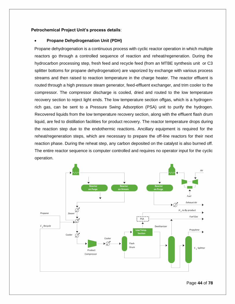
Propane Dehydrogenation Unit (PDH)
Propane dehydrogenation is a continuous process with cyclic reactor operation in which multiple
reactors go through a controlled sequence of reaction and reheat/regeneration. During the
hydrocarbon processing step, fresh feed and recycle feed (from an MTBE synthesis unit or C3
splitter bottoms for propane dehydrogenation) are vaporized by exchange with various process
streams and then raised to reaction temperature in the charge heater. The reactor effluent is
routed through a high pressure steam generator, feed-effluent exchanger, and trim cooler to the
compressor. The compressor discharge is cooled, dried and routed to the low temperature
recovery section to reject light ends. The low temperature section offgas, which is a hydrogen-
rich gas, can be sent to a Pressure Swing Adsorption (PSA) unit to purify the hydrogen.
Recovered liquids from the low temperature recovery section, along with the effluent flash drum
liquid, are fed to distillation facilities for product recovery. The reactor temperature drops during
the reaction step due to the endothermic reactions. Ancillary equipment is required for the
reheat/regeneration steps, which are necessary to prepare the off-line reactors for their next
reaction phase. During the reheat step, any carbon deposited on the catalyst is also burned off.
The entire reactor sequence is computer controlled and requires no operator input for the cyclic
operation.
Air
Propane
Product Compressor
PSA
Reactor on Purge
Reactor on Stream
Reactor on Purge
Low Temp. Section
C 3 Recycle
Steam
Cooler Cooler
Fuel
Fuel Gas
Propylene
Exhaust Air
Deethanizer
H 2 to By-product
C 3 Splitter
Flash Drum

Page 45 of 78
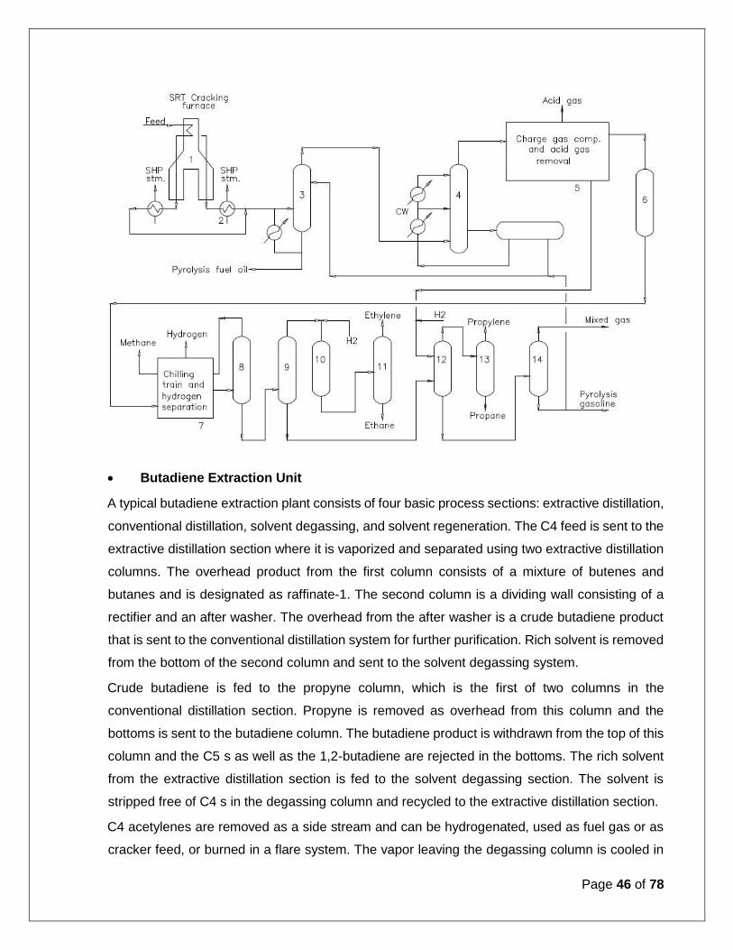
Ethylene cracker and associated units:
Hydrocarbon feedstock like Naphtha,LPG and off gases is preheated and cracked in the
presence of steam in tubular SRT (short residence time) pyrolysis furnaces (1) this approach
features extremely high olefin yields, long run length and mechanical integrity. The products exit
the furnace at 1,500°F to 1,600°F and are rapidly quenched in the transfer line exchangers (2)
that generate super high-pressure (SHP) steam.
Furnace effluent, after quench, flows to the gasoline fractionator (3) where the heavy oil fraction
is removed from the gasoline and lighter fraction (liquids cracking only). Further cooling of
furnace effluents is accomplished by a direct water quench in the quench tower (4) raw gas from
the quench tower is compressed in a multistage centrifugal compressor (5) to greater than 500
psig. The compressed gas is then dried (6). The chilled. Hydrogen is recovered in the chilling
train (7) which feeds the demethanizer (8). The demethanizer operates at about 100 psia,
providing increased energy efficiency. The bottoms from the demethanizer go to the deethanizer
(9).
Acetylene in the deethanizer overhead is hydrogenated (10). The ethylene-ethane stream is
fractionated (11) and polymer-grade ethylene is recovered. Ethane leaving the bottom of the
ethylene fractionator is recycled and cracked to extinction.
The deethanizer bottoms and condensate stripper bottoms from the charge compression system
are depropanized (12). The depropanizer bottoms is separated into mixed C4 and light gasoline
streams (14). Polymer-grade propylene is recovered in a propylene fractionator (13).
The schematic flow diagram for Ethylene cracker is presented as below:
Page 46 of 78
Butadiene Extraction Unit
A typical butadiene extraction plant consists of four basic process sections: extractive distillation,
conventional distillation, solvent degassing, and solvent regeneration. The C4 feed is sent to the
extractive distillation section where it is vaporized and separated using two extractive distillation
columns. The overhead product from the first column consists of a mixture of butenes and
butanes and is designated as raffinate-1. The second column is a dividing wall consisting of a
rectifier and an after washer. The overhead from the after washer is a crude butadiene product
that is sent to the conventional distillation system for further purification. Rich solvent is removed
from the bottom of the second column and sent to the solvent degassing system.
Crude butadiene is fed to the propyne column, which is the first of two columns in the
conventional distillation section. Propyne is removed as overhead from this column and the
bottoms is sent to the butadiene column. The butadiene product is withdrawn from the top of this
column and the C5 s as well as the 1,2-butadiene are rejected in the bottoms. The rich solvent
from the extractive distillation section is fed to the solvent degassing section. The solvent is
stripped free of C4 s in the degassing column and recycled to the extractive distillation section.
C4 acetylenes are removed as a side stream and can be hydrogenated, used as fuel gas or as
cracker feed, or burned in a flare system. The vapor leaving the degassing column is cooled in

Page 47 of 78
a separate cooling column or heat exchanger, compressed, and sent back to the extractive
distillation section. A sophisticated heat recovery system utilizes most of the sensible heat of the
solvent, resulting in extremely low energy consumption. A small solvent stream is continuously
fed to the NMP regeneration section. The solvent is heated with steam under vacuum conditions
in a regeneration vessel. Vaporized NMP is condensed and recycled to the extractive distillation
section. The remaining residue is usually incinerated.
Butene-1:
The process for 1-butene production has two sections: butene isomerization and butene
fractionation. In the butene isomerization section, raffinate-2 feed from OSBL is mixed with
butene recycle from the butene fractionation section and is vaporized, preheated and then fed
to the butene isomerization reactor where 2-butene is isomerized to 1-butene over a fixed bed
of proprietary isomerization catalyst. The reaction is equilibrium limited, so the reactor effluent
contains both 1-butene and 2-butene. Reactor effluent is then cooled and condensed and flows
to the butene fractionation section.
In the butene fractionation section, isomerization reactor effluent is separated into 1-butene
product and recycle 2-butene in a butene fractionator. The 1-butene product is separated
overhead and recycle 2-butene and butane contained in the feed are produced from the bottom.
The column uses a heat pump system to efficiently separate 1-butene from 2-butene and butane
with no external heat input. A portion of the bottoms is purged to remove the butane in the feed
together with some 2-butene before it is recycled to the isomerization reactor. There are also
number of options for upstream processing of C4 feed including Selective C4 hydrogenation,

Page 48 of 78
MTBE production or isobutene/ isobutane removal so that raw C4 s, raffinate-1 or raffinate-2 can
be processed to make 1-butene.
MTBE/ETBE:
MTBE is formed by the catalytic etherification of isobutylene with methanol. The process is based
on a two-step reactor design, consisting of a boiling point fixed bed reactor followed by final
conversion in a catalytic distillation column. The process uses an acidic ion exchange resin
catalyst in both its fixed bed reactor and proprietary catalytic distillation structures. The boiling
point reactor is designed so the liquid is allowed to reach its boiling point by absorbing the heat
of reaction, after which a limited amount of vaporization takes place, thereby maintaining precise
temperature control.
The maximum temperature is adjusted by setting the total system pressure. Since the reacting
liquid mixture temperature cannot exceed the boiling temperature, control is far superior to those
systems in which heat must be transferred by convection or conduction. This design retains the
heat of reaction as latent heat, reducing heat input requirements for the ensuing fractionation.
The unique catalytic distillation column combines reaction and fractionation in a single unit
operation. It allows a high conversion of isobutylene (exceeding fixed bed equilibrium limitations)
to be achieved simply and economically.

Page 49 of 78
By using distillation to separate the product from the reactants, the equilibrium limitation is
exceeded and higher conversion of isobutylene is achieved. Catalytic distillation also takes
advantage of the improved kinetics through increased temperature without penalizing equilibrium
conversion. MTBE synthesis is a highly selective process for removal of isobutylene. It can be
used for pretreatment to produce high purity butene-1 or for recovery to make high purity
isobutylene via MTBE decomposition.
Aromatic Complex/ Para xylene/Benzene:
The recovery section of an aromatics complex based on the feed from a CCR would typically
include the following processes:
A reformate splitter, where reformate is separated into a C7- overhead stream and a C8+ bottoms
stream.
A solvent extraction unit, where aromatics compounds in the overhead stream from the reformate
splitter are separated from the other components.
A BT fractionation complex, in which benzene and toluene are recovered and separated by
distillation.
A xylenes recovery section, where the C8+ fraction would be passed, after treatment, for
recovery of paraxylene from the mixed xylenes stream. The Boiling points of Para Xylene, Ortho
Xylene and Meta Xylene are very close and can’t be separated by fractional distillation.
Historically, crystallization processes were primarily used for paraxylene recovery; these have

Page 50 of 78
now largely been superseded by adsorption systems, though crystallization is still sometimes the
most economical route where paraxylene concentration in the feed stream is high.
In addition to recovery of the aromatics already present in the reformate stream, various
technologies also exist to maximize the production of certain aromatics species. The most
important of in relation to the production of paraxylene is isomerization, in which the effluents
from the paraxylene recovery process containing predominantly Ethylbenzene, orthoxylene and
metaxylene, are isomerized to create further paraxylene.
The reformate stream typically contains around 20% by weight toluene. This can be sold for
gasoline blend-stock (it has a high octane value and therefore an attractive blend value), or as a
chemical feedstock, for which there is a stable, though small demand in India. Alternatively, the
toluene can be used as feedstock to a THDA, TDP or transalkylation unit as described below, to
make further xylenes and / or benzene.
Toluene Hydrodealkylation (HDA), in which toluene is converted to benzene.
Toluene Disproportionation (TDP) in which toluene is converted into a mixture of benzene and
xylenes. More recent processes, known as STDP (Selective Toluene Disproportionation), are
capable of producing a very much higher yield of paraxylene, typically around 90% of the xylenes
stream as compared with TDP which yields around 25% paraxylene in xylenes.
Transalkylation, in which toluene, and aromatic C9’s, are converted into xylenes.

Page 51 of 78
PTA:
The Oxidation Plant is designed for continuous operation and consists of five main sections:
Reaction, CTA Crystallisation, Separation & Drying, Catalyst Recovery and Solvent Recovery.
In the Reaction section paraxylene feedstock is mixed with acetic acid solvent and catalyst
solution and reacted with air. The major proportion of the terephthalic acid produced in the
exothermic reaction is precipitated to form a slurry in the reactor. In the CTA Crystallisation
section the reactor exit slurry is depressured and cooled in a series of three crystallising vessels.
The precipitated terephthalic acid product is recovered in the Separation and Drying section by
continuous filtration incorporating a solvent wash stage. A proportion of the mother liquor
generated in this stage is purged to Catalyst Recovery. Residual solvent acetic acid in the filter
cake is removed in a continuous drier. The resultant product is conveyed to intermediate storage
on the Purification Plant.
In the Catalyst Recovery Section, catalyst is recovered from the Oxidation Plant mother liquor
purge. The composition of recovered catalyst is adjusted to produce a catalyst solution for feed
to the Reaction Section.
US West Coast Averages
Reformer
Isomer- isation
Solvent Extraction
PX recovery
BTX recovery
NHT Naphtha
Benzene
Toluene
Raffinate
Paraxylene Reformate Splitter
Xylenes Splitter
C9/C10
aromatics
Aromatics Complex

Page 52 of 78
In the Solvent Recovery Section, impure solvent recovered from the Reaction, Catalyst Recovery
and CTA Recovery Sections, is processed to remove acetic acid and water from the higher
boiling reaction by-products. The recovered solvent is fractionated to remove low-boiling
impurities and the water of reaction, and produces purified acetic acid suitable for re-use in the
Plant. The higher-boiling by-products are quench cooled in water and the resulting slurry
transferred to OSBL.
LAB:
The reactor (1) dehydrogenates the feed into corresponding linear olefin. Reactor effluent is
separated into gas and liquid phases in a separator (2). Diolefins in the separator liquid are
selectively converted back to mono-olefins in the reactor (3). Light ends are removed from
reactor effluent in a stripper (4). The olefin paraffin mixture is then alkylated with benzene in the
fixed-bed Detal reactor (5). Product from the reactor flows to the fractionation section (6) for
separation and recycle of unreacted benzene to the reactor, and unreacted paraffins are
separated (7) and recycled. A return column (8) separates the LAB product from the heavy
alkylate bottoms stream.

Page 53 of 78
The process is nonpolluting. No process waste streams are produced. The catalysts used are
non-corrosive and require no special handling. The schematic flow diagram for Linear
Alkylbenzene is presented below:
Polypropylene:
The process is a modular technology consisting of three main process steps – catalyst and raw
material feeding, polymerization and finishing. The catalyst, liquid propylene and hydrogen for
molecular weight control are continuously fed into the loop reactor. The bulk polymerization
typically occurs in two tubular loop reactors filled with liquid propylene and optional gas-phase
copolymerization reactors. Reduced reactor residence time and economically optimized
equipment sizing can be achieved relative to other technologies, due to the high monomer
density and increased catalyst activity. The finishing section consists of highly efficient liquid
propylene vaporization operations at very high polypropylene concentrations, separation of the
unconverted monomers, and complete recycling of the monomers back to the reactor. The
schematic flow diagram for Polypropylene is shown in figure below:

Page 54 of 78
LLDPE/HDPE:
Catalyst components are mixed and fed directly to prepolymerization (1) with a light inert
hydrocarbon, where a first bulk polymerization occurs under mild controlled conditions. This step
exploits the catalyst system potential in terms of morphology, mileage and complete reliability in
the following gas-phase reaction sections. The slurry flows continuously into the first gas-phase
reactor (GPR) (3) Reactor gas is circulated at high speed by a centrifugal compressor through a
distribution grid. A cooler on the circulation gas loop (2) removes the reaction heat.
Polymer quality and reaction rate are controlled by gas composition, monomer feed rate and
residence time. Product is continuously discharged from the first GPR, via a proprietary device
to a second GPR (5) with similar configuration. Resultant discharged gas is recovered and no
gas enters the second GPR due to a proprietary “lock-hopper” system (4). Thus, an independent
gas composition can be built up and maintained in each GPR, allowing growth to a different, if
required, polymer within the polymeric matrix resulting from the first stage. Pressure and
temperature in the GPRs are also independently controlled; no additional feed of catalytic
components is required.
The polymer is then discharged in a receiver recovering the resultant gas (6) and to a proprietary
unit for monomer stripping and catalyst deactivation in the polymer spheres (7) Residual
hydrocarbons are stripped out and recycled to reaction, while the polymer is dried by a closed-

Page 55 of 78
loop nitrogen system (8) and, free volatile substances, it is sent to liquid and/or solid additives
incorporation step before extrusion. The schematic flow diagram for Polyethylene (lldpe/hdpe) is
presented in
HDPE:
HDPE is produced by catalytic polymerisation of ethylene in either slurry (suspension), solution
or gas phase reactors. Alpha-olefin comonomers, such as butene, hexene and octene, may be
incorporated at low levels to modify the polymer's properties.
The choice of catalyst and/or the use of bimodal processes are used to modulate the quality of
the output. The traditional Ziegler-Natta and chromium catalysts have been augmented by
metallocene catalysts which are claimed to give improved properties. Metallocenes also allow
slurry loop operators to enter the LLDPE market, blurring the historical boundaries between the
PEs. Bimodal processes, using twin slurry or gas phase or a combination of reactors, claim to
produce resins competitive with those from metallocenes.
The Process for the production of high density polyethylene operates at low temperature and
pressure. Polymerisation takes place in a slurry loop reactor system where the polymer particles
grow whilst suspended in an inert light hydrocarbon diluent which can contain a mixture of

Page 56 of 78
ethylene, hydrogen and comonomer. Slurry is withdrawn from the reactor and the HDPE Flake
is separated from the hydrocarbon diluent and un-reacted monomers. These hydrocarbons are
recycled to the reactors in a simple recovery system. HDPE Flake which leaves the reactor then
enters a simple degassing system to remove trace diluent and is then transferred to the finishing
sector. In the finishing sector, the flake is mixed with additives and is palletised. The pellets are
then homogenized and transferred to the packaging facility.The schematic flow diagram for
HDPE is shown below
LDPE/EVA:
In the autoclave process, polymerization grade ethylene is received at the battery limits of the
plant. This is then mixed with ethylene (containing traces of modifier/co-monomer) from the purge
gas compressor and fed to the series of reciprocating compressors where the pressure is
increased to very high pressure about 2100 bar.
The compressor discharge stream is fed to the different ethylene feed inlets of the reactor.
Reactor operating temperature and Pressure are near to 215 oC and 2000 Bar. Reactor effluent
is typically cooled down to 15°C. The hot gas/polymer mixture leaving the autoclave reactor is
then cooled in the High Pressure Product Cooler.
At the exit of the HP product cooler, the reaction fluid is decompressed through the high pressure
letdown valve. The molten polymer from the bottom of the HPS is decompressed to about 0.5
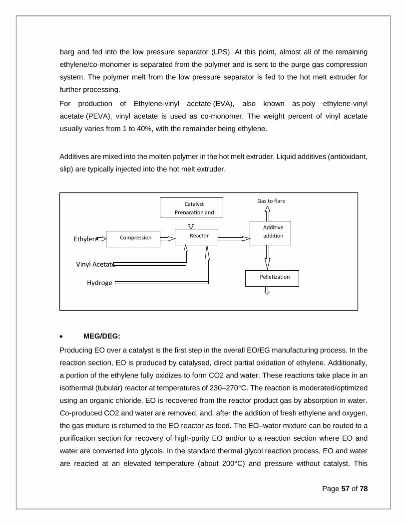
Page 57 of 78
barg and fed into the low pressure separator (LPS). At this point, almost all of the remaining
ethylene/co-monomer is separated from the polymer and is sent to the purge gas compression
system. The polymer melt from the low pressure separator is fed to the hot melt extruder for
further processing.
For production of Ethylene-vinyl acetate (EVA), also known as poly ethylene-vinyl
acetate (PEVA), vinyl acetate is used as co-monomer. The weight percent of vinyl acetate
usually varies from 1 to 40%, with the remainder being ethylene.
Additives are mixed into the molten polymer in the hot melt extruder. Liquid additives (antioxidant,
slip) are typically injected into the hot melt extruder.
MEG/DEG:
Producing EO over a catalyst is the first step in the overall EO/EG manufacturing process. In the
reaction section, EO is produced by catalysed, direct partial oxidation of ethylene. Additionally,
a portion of the ethylene fully oxidizes to form CO2 and water. These reactions take place in an
isothermal (tubular) reactor at temperatures of 230–270°C. The reaction is moderated/optimized
using an organic chloride. EO is recovered from the reactor product gas by absorption in water.
Co-produced CO2 and water are removed, and, after the addition of fresh ethylene and oxygen,
the gas mixture is returned to the EO reactor as feed. The EO–water mixture can be routed to a
purification section for recovery of high-purity EO and/or to a reaction section where EO and
water are converted into glycols. In the standard thermal glycol reaction process, EO and water
are reacted at an elevated temperature (about 200°C) and pressure without catalyst. This
Catalyst
Preparation and
Additive
addition Compression Reactor
Pelletization
Ethylen
e
Hydroge
n
Vinyl Acetate
Gas to flare
Pellets

Page 58 of 78
process typically yields about 90–92% monoethylene glycol (MEG) and 8–10% heavier glycol
products, mainly diethylene glycol (DEG) and triethylene glycol (TEG). The proportion of the
higher glycols is limited by using excess water to minimize the reaction between the EO and
glycols. The resultant water–glycol mixture from the reactor is then fed to multiple evaporators
where the excess water is recovered and largely recycled. Finally, the water-free glycol mixture
is separated by distillation into MEG and the higher glycols a more modern technology is to react
EO with CO2 to form ethylene carbonate (EC) and subsequently react the EC with water to form
MEG, both reactions being catalysed. In this two-step process, most of the MEG forms in an EO-
free environment, which minimizes the co-production of heavier glycols and results in a MEG
yield of more than 99%. Figure 2 shows a basic overview of the EO/EG process.
Ethyl Benzene/Styrene Monomer:
Ethylbenzene is produced from benzene and either polymer-grade ethylene or an
ethylene/ethane feedstock using the alkylation and trans-alkylation process and proprietary
alkylation and transalkylation catalysts.
Ethylbenzene (EB) is dehydrogenated to styrene over potassium-promoted iron oxide catalyst in
the presence of low steam to oil to achieve high styrene selectivity. Byproduct benzene and
toluene are recovered via distillation with the benzene fraction being recycled to the EB unit.
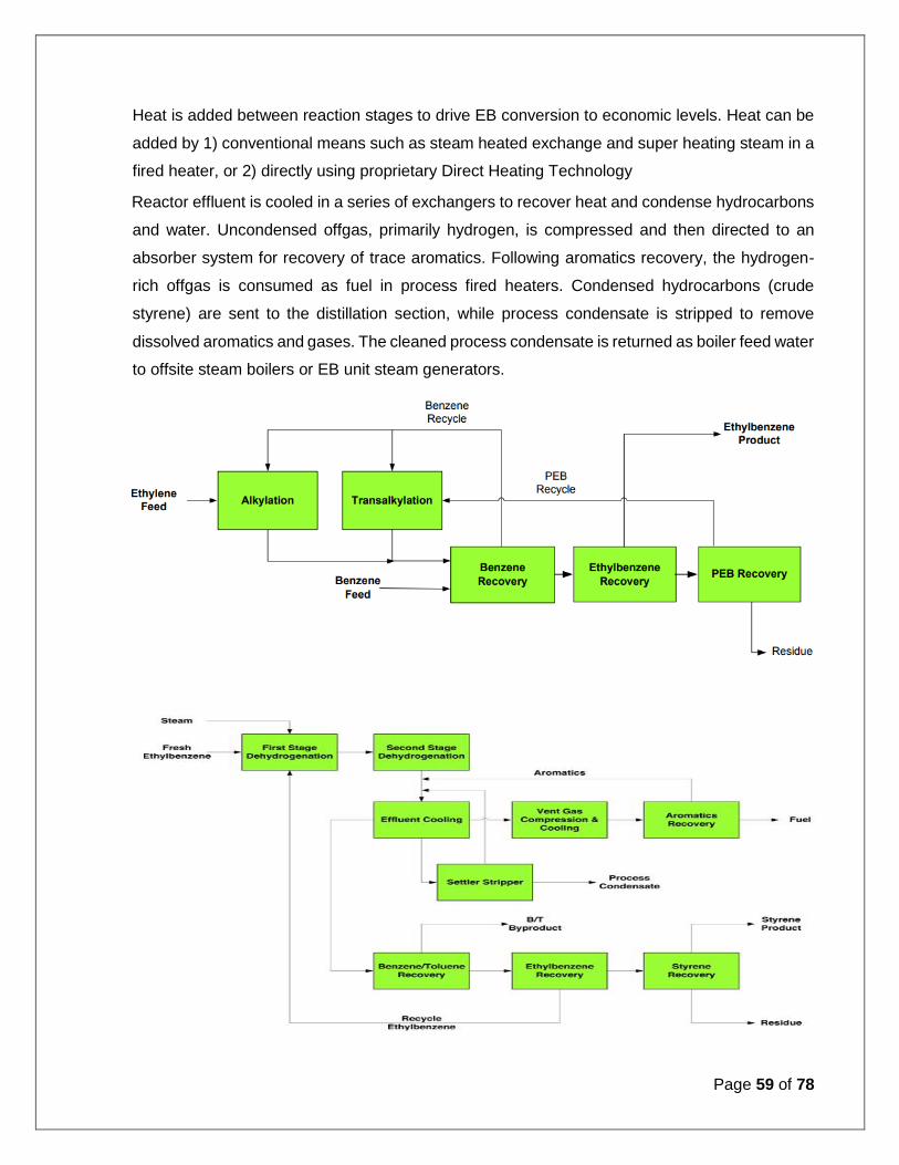
Page 59 of 78
Heat is added between reaction stages to drive EB conversion to economic levels. Heat can be
added by 1) conventional means such as steam heated exchange and super heating steam in a
fired heater, or 2) directly using proprietary Direct Heating Technology
Reactor effluent is cooled in a series of exchangers to recover heat and condense hydrocarbons
and water. Uncondensed offgas, primarily hydrogen, is compressed and then directed to an
absorber system for recovery of trace aromatics. Following aromatics recovery, the hydrogen-
rich offgas is consumed as fuel in process fired heaters. Condensed hydrocarbons (crude
styrene) are sent to the distillation section, while process condensate is stripped to remove
dissolved aromatics and gases. The cleaned process condensate is returned as boiler feed water
to offsite steam boilers or EB unit steam generators.
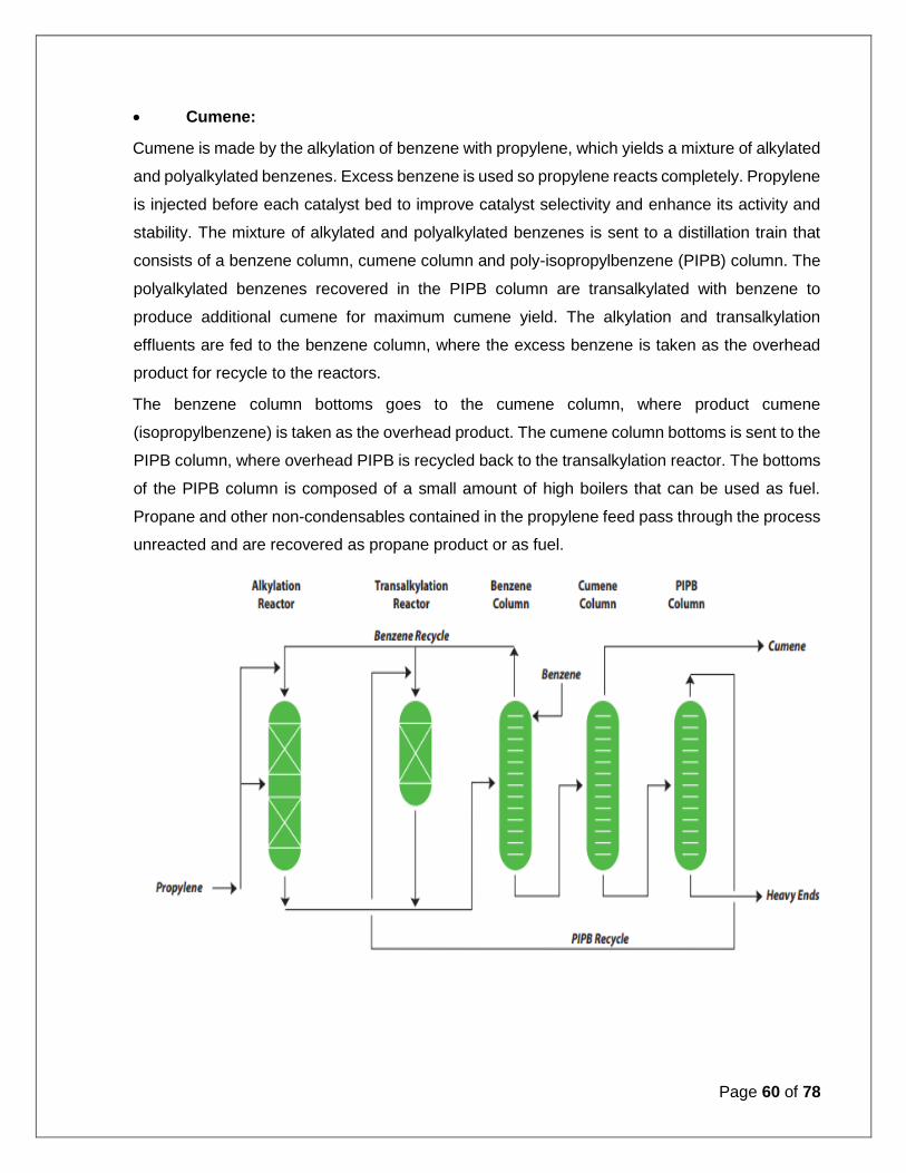
Page 60 of 78
Cumene:
Cumene is made by the alkylation of benzene with propylene, which yields a mixture of alkylated
and polyalkylated benzenes. Excess benzene is used so propylene reacts completely. Propylene
is injected before each catalyst bed to improve catalyst selectivity and enhance its activity and
stability. The mixture of alkylated and polyalkylated benzenes is sent to a distillation train that
consists of a benzene column, cumene column and poly-isopropylbenzene (PIPB) column. The
polyalkylated benzenes recovered in the PIPB column are transalkylated with benzene to
produce additional cumene for maximum cumene yield. The alkylation and transalkylation
effluents are fed to the benzene column, where the excess benzene is taken as the overhead
product for recycle to the reactors.
The benzene column bottoms goes to the cumene column, where product cumene
(isopropylbenzene) is taken as the overhead product. The cumene column bottoms is sent to the
PIPB column, where overhead PIPB is recycled back to the transalkylation reactor. The bottoms
of the PIPB column is composed of a small amount of high boilers that can be used as fuel.
Propane and other non-condensables contained in the propylene feed pass through the process
unreacted and are recovered as propane product or as fuel.

Page 61 of 78
Phenol/Acetone:
The major processing steps include: (1) liquid phase oxidation of cumene to cumene
hydroperoxide [CHP], (2) concentration of CHP, (3) acid-catalyzed decomposition of
concentrated CHP to phenol and acetone, (4) neutralization of acidic decomposition product, (5)
fractionation of the neutralized decomposition product for recovery of acetone, phenol, AMS and
residue, (6) recovery of phenol and the effluent waste water via an extraction process to prepare
it for further downstream treatment required to meet effluent quality specifications, and (7)
hydrogenation of AMS back to cumene for recycling to synthesis; or, optionally, refining of AMS
for sale as a product.
Bisphenol A:
In the BPA condensation reactors, phenol and acetone react over an ion-exchange resin catalyst
in the presence of a homogeneous promoter and excess phenol, to produce bisphenol-A, water
and various byproducts. The catalyst system has a long catalyst life.
The water of reaction and the small amount of unreacted acetone are removed from the reactor
effluent by distillation. Acetone is recycled to the reactor system. No acetone purge is required
with this process. The reaction water is sent to the waste recovery system, from which
wastewater suitable for bio treatment and phenol suitable for recycle to the reaction system are
produced. The dehydration effluent is concentrated to a BPA level suitable for crystallization.

Page 62 of 78
BPA is separated from byproducts in a proprietary solvent crystallization and recovery system to
produce the adduct of p, p BPA and phenol. Mother liquor from the purification system is distilled
in the solvent recovery section to recover dissolved solvent. The solvent-free mother liquor
stream is recycled to the reaction system. A purge from the mother liquor is sent to the waste
recovery system.
Single train designs as large as 200kta or as small as 60kta are available.
The purified adduct is processed in a BPA finishing system to remove phenol from the product,
and the resulting molten BPA is solidified in the prill tower to produce prills suitable for the
merchant BPA market, including polycarbonate production.
Polycarbonate:
BPA and DPC are fed into the preparation tank where they are thoroughly molten. In order to
achieve the high-purity monomer required for the production of high-quality polycarbonate
suitable purification steps such as distillation, filtration and melt crystallization are considered.
The pre-heated raw materials are fed in liquid form in a defined molar ratio into the
transesterification reactor where they are mixed with catalysts and heated up to the desired
transesterification temperature. During the formation of polymer chains phenol begins to split-
off. After the transesterification has been finished the short polymer chains, the so-called
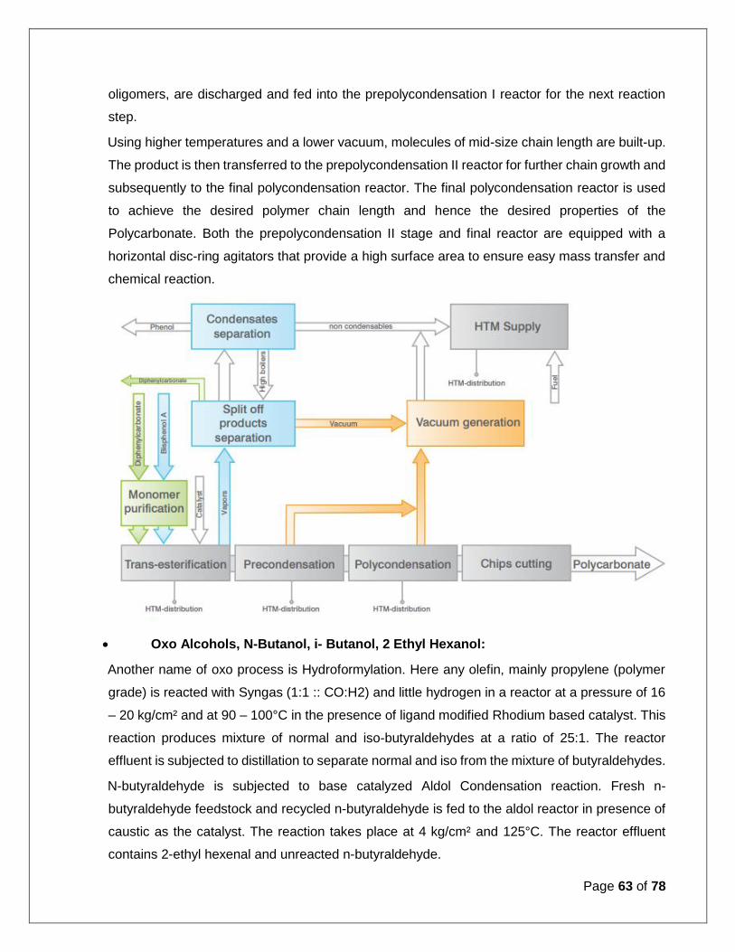
Page 63 of 78
oligomers, are discharged and fed into the prepolycondensation I reactor for the next reaction
step.
Using higher temperatures and a lower vacuum, molecules of mid-size chain length are built-up.
The product is then transferred to the prepolycondensation II reactor for further chain growth and
subsequently to the final polycondensation reactor. The final polycondensation reactor is used
to achieve the desired polymer chain length and hence the desired properties of the
Polycarbonate. Both the prepolycondensation II stage and final reactor are equipped with a
horizontal disc-ring agitators that provide a high surface area to ensure easy mass transfer and
chemical reaction.
Oxo Alcohols, N-Butanol, i- Butanol, 2 Ethyl Hexanol:
Another name of oxo process is Hydroformylation. Here any olefin, mainly propylene (polymer
grade) is reacted with Syngas (1:1 :: CO:H2) and little hydrogen in a reactor at a pressure of 16
– 20 kg/cm² and at 90 – 100°C in the presence of ligand modified Rhodium based catalyst. This
reaction produces mixture of normal and iso-butyraldehydes at a ratio of 25:1. The reactor
effluent is subjected to distillation to separate normal and iso from the mixture of butyraldehydes.
N-butyraldehyde is subjected to base catalyzed Aldol Condensation reaction. Fresh n-
butyraldehyde feedstock and recycled n-butyraldehyde is fed to the aldol reactor in presence of
caustic as the catalyst. The reaction takes place at 4 kg/cm² and 125°C. The reactor effluent
contains 2-ethyl hexenal and unreacted n-butyraldehyde.

Page 64 of 78
2-ethyl hexenal is separated and hydrogenated to produce 2-Ethyl Hexanol in another reactor in
presence of supported nickel catalyst in a typical condition of 35 kg/cm² and 150°C. 2-Ethyl
Hexanol thus produced is further subjected to distillation to get it in the purest form.
N-butanol (Normal Butyl Alcohol) is produced by hydrogenating n-butyraldehyde in presence of
slurry based nickel catalyst. Fresh n-butyraldehyde feedstock and recycled n-butyraldehyde is
fed to the autoclave reactor, which contains catalyst, along with hydrogen. Typical reactor
condition is 10 kg/cm² and 200°C. The crude n-butanol is removed from the catalyst slurry and
distilled to get pure n-butanol product.
I-butanol (Iso Butyl Alcohol) is produced by the same way as n-butanol using
i-butyraldehyde as the feedstock. Catalyst and rector condition are also similar to that of the n-
butanol.
Acrylic Acid/ Acrylates:
Stages of Acrylic Acid production based on the oxidation of Propylene are synthesis gas
preparation, Synthesis section (Propylene oxidation and Acrolein oxidation), Acrylic Acid
absorption, cracking section, Stabilization and Crystallization of Acrylic Acid.
Liquid Propylene is evaporated and fed to the reactor section. Ambient air is compressed to and
fed at a constant ratio to the Propylene oxidation reactor. The reactors of both oxidation stages
are multi-tubular fixed bed reactors. In the first stage reactor Propylene reacts with oxygen to
form Acrolein in contact with the catalyst 1 based on bismuth–molybdenum oxide. To control the
reaction temperatures (300 to 380°C) reaction heat is transferred to a salt bath. Similarly the
reaction gas mixture is fed together with the secondary air to the second stage reactor.

Page 65 of 78
The reaction gas coming from reactor is fed to a gas cooler and cooled gas is sent to the sump
area of the absorption column. In the absorption column Acrylic Acid is absorbed by water, which
is sent as reflux from the top of the tower. The part is sent to the HRU for thermal treatment.
Oligomers from Acrylic Acid and high boiling side products are sent from the sump area of the
absorption tower to a cracking tower, where dimers of Acrylic Acid are thermally cracked and
send back the absorption column. Acrylic Acid is withdrawn from the absorption at a purity > 80
wt. % and is sent to a crystallization unit for further purification. Acrylic Acid from absorption
column is cooled to freezing point and sent to a crystallization unit. Pure Acrylic Acid is recovered
by forming crystals.
Butyl Acrylates process includes Esterification section, distillation and catalyst recovery, lights
separation and n-butanol recovery. In esterification section, acrylic acid, n-butanol and catalyst
mixed with recycle streams after preheating sent to reactor vessels. Water is removed from the
reactors by distillation. Reactor outlet is sent to azeotropic distillation column where raw BA is
recovered and sent to final distillation column to get pure BA.
For NPG production, first the synthesis of hydroxypivalinaldehyde (HPA) is performed by
aldolization reaction of aqueous formaldehyde and i-butyraldehyde in presence of catalyst.
Further by hydrogenation of HPA to NPG (neo pentyl glycol) is performed by using copper
catalyst at high pressure (40 kg/cm2) and moderate temperature (100-130 deg C). The crude
NPG is separated from water and byproducts by distillation in two consecutive distillation towers.
Solidification is performed on flaker belt by feeding NPG melt.
In case of SAP, monomer mix is first prepared from acrylic acid, caustic, DM water and
crosslinking monomer. This is transferred to the reactor where exothermic polymerization
reaction takes place. The polymer particles formed in the first process stage are post cross-
linked for further property enhancement. After surface crosslinking step, product is cooled down
and post-treatment takes place.
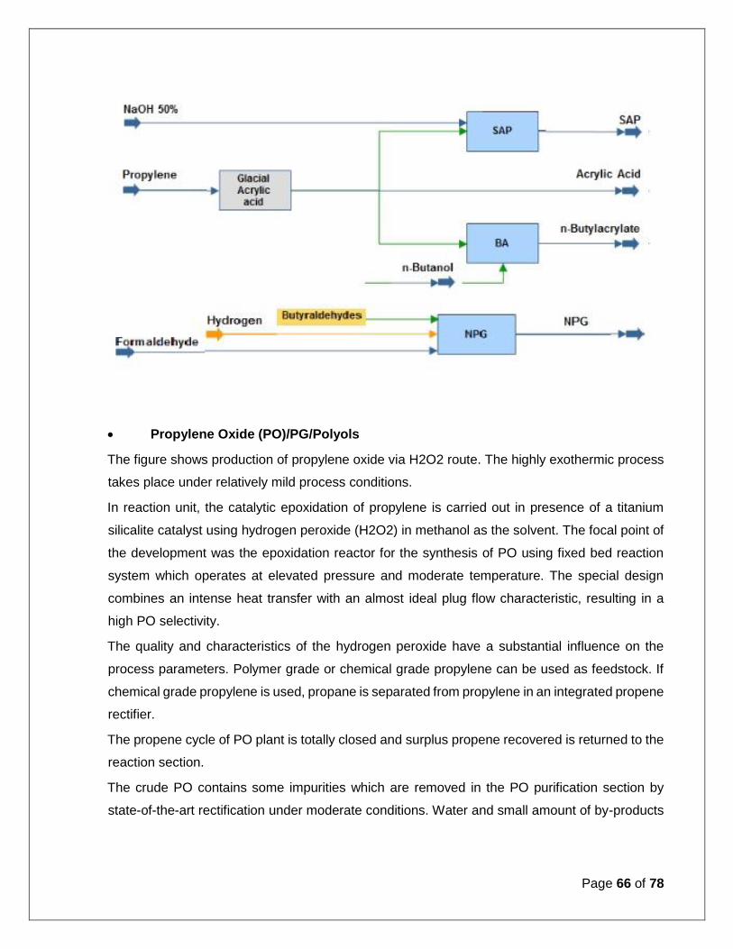
Page 66 of 78
Propylene Oxide (PO)/PG/Polyols
The figure shows production of propylene oxide via H2O2 route. The highly exothermic process
takes place under relatively mild process conditions.
In reaction unit, the catalytic epoxidation of propylene is carried out in presence of a titanium
silicalite catalyst using hydrogen peroxide (H2O2) in methanol as the solvent. The focal point of
the development was the epoxidation reactor for the synthesis of PO using fixed bed reaction
system which operates at elevated pressure and moderate temperature. The special design
combines an intense heat transfer with an almost ideal plug flow characteristic, resulting in a
high PO selectivity.
The quality and characteristics of the hydrogen peroxide have a substantial influence on the
process parameters. Polymer grade or chemical grade propylene can be used as feedstock. If
chemical grade propylene is used, propane is separated from propylene in an integrated propene
rectifier.
The propene cycle of PO plant is totally closed and surplus propene recovered is returned to the
reaction section.
The crude PO contains some impurities which are removed in the PO purification section by
state-of-the-art rectification under moderate conditions. Water and small amount of by-products

Page 67 of 78
are removed in the methanol processing section and the purified solvent is recycled to the
reactor.
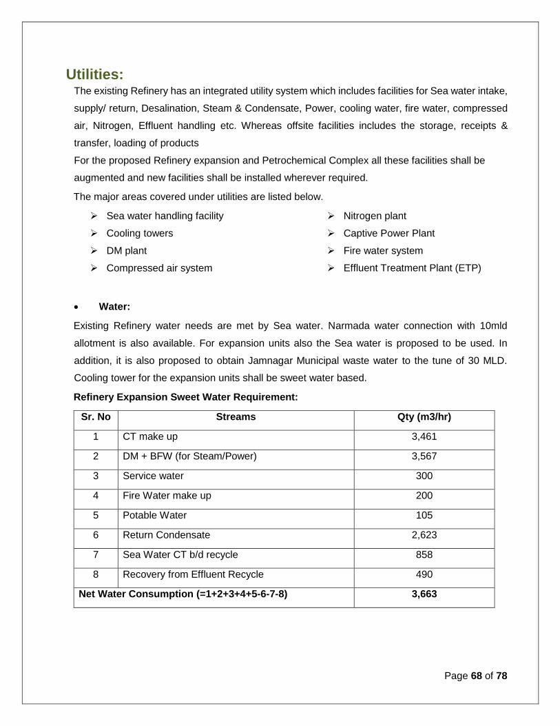
Page 68 of 78
Utilities: The existing Refinery has an integrated utility system which includes facilities for Sea water intake,
supply/ return, Desalination, Steam & Condensate, Power, cooling water, fire water, compressed
air, Nitrogen, Effluent handling etc. Whereas offsite facilities includes the storage, receipts &
transfer, loading of products
For the proposed Refinery expansion and Petrochemical Complex all these facilities shall be
augmented and new facilities shall be installed wherever required.
The major areas covered under utilities are listed below.
Sea water handling facility
Cooling towers
DM plant
Compressed air system
Nitrogen plant
Captive Power Plant
Fire water system
Effluent Treatment Plant (ETP)
Water:
Existing Refinery water needs are met by Sea water. Narmada water connection with 10mld
allotment is also available. For expansion units also the Sea water is proposed to be used. In
addition, it is also proposed to obtain Jamnagar Municipal waste water to the tune of 30 MLD.
Cooling tower for the expansion units shall be sweet water based.
Refinery Expansion Sweet Water Requirement:
Sr. No Streams Qty (m3/hr)
1 CT make up 3,461
2 DM + BFW (for Steam/Power) 3,567
3 Service water 300
4 Fire Water make up 200
5 Potable Water 105
6 Return Condensate 2,623
7 Sea Water CT b/d recycle 858
8 Recovery from Effluent Recycle 490
Net Water Consumption (=1+2+3+4+5-6-7-8) 3,663

Page 69 of 78
Petrochemical Sweet Water Requirement:
Sr. No Streams Qty (m3/hr)
1 CT make up 6,335
2 DM + BFW (for Steam/Power) 4,032
3 Service water 300
4 Fire Water make up 100
5 Potable water 90
6 Return Condensate 2,033
7 Recovery from Effluent Recycle 1019
Net Water Consumption (=1+2+3+4+5-6-7) 7805
Based on above the additional Sea water requirement for “Expansion Units” shall be approximately
30,178 m3/hr as under:
Sr. No. Project Unit Sea Water Requirement
1 Refinery Expansion m3/hr 9,639
2 Petrochemical Project m3/hr 20,539
With above the projected sea water demand for 46MMPTA Refinery with Petrochemical Project
works out as 38,678 m3/hr.
At present there are 03 desalination units:
02 Units of Thermal Desalination 390 m3/hr each
01 unit of Thermal Desalination 1000 m3/hr
Desalination units of suitable capacity shall be installed to meet the expansion requirement.
Desalinated water shall be supplied for uses including cooling water make up, DM water feed and
potable water.
As per the existing EC (expiring on 15th Sep 18) for 60 MMTPA Refinery and Petrochemical
Complex, provision for supply and return of sea water was made through following sources:

Page 70 of 78
By suitable augmentation of existing Supply and return facilities at DPT waters in Pathfinder
creek
New supply and return facilities at Salaya Creek through 3rd party facility.
For our proposed Refinery expansion (20 MMTPA to 46 MMTPA) and Petrochemical Project, we
propose to follow the same methodology. Any modification at supply and return facilities shall be
finalised in consultation with NIO and other concerned agencies/ authorities.
All these options shall be evaluated and final one shall be suggested while submitting EIA.
Brine from the Desalination units, shall be discharged in the sea. New line, as per requirement,
with appropriate diffuser shall be laid for the same. The estimated quantity of Sea Water Brine for
the Expansion Units shall be 18,271 m3/hr.
With above the projected sea water discharge for 46MMPTA Refinery with Petrochemical Project
from desalination units, cooling tower blow down shall be approximately 23,881 m3/hr.
Effluent Treatment Plant:
Effluent treatment plant, designed to meet Minimal National Standards (MINAS), shall be
installed to collect and treat waste water generated.
Effluent generated from the project shall be as follows:
Sr. No. Project Unit Effluent Generated
1 Refinery Expansion m3/hr 1,177
2 Petrochemical Project m3/hr 1,618
Total m3/hr 2,795
With above the projected Effluent generation for 46MMPTA Refinery with Petrochemical Project
works out as 3,870 m3/hr
Water conservation measures shall be implemented to reuse/ recycle the treated water. The
treated water shall be re used for service water, Fire water make up and horticulture. A part of

Page 71 of 78
treated water shall be desalinated through RO and shall be used for cooling water make up and
DM feed.
Power Requirement:
The power requirement of the existing Refinery is met by Captive power plant consisting of Coal/
NG/ FO/ CSO/HSD based steam and power generators installed & operated by our subsidiary
Vadinar Power Company Ltd. (VPCL).
The details of the existing power generation facilities are as follows:
Sr.
No
Existing Asset Fuel Power Capacity
(MW)
1 77 MW Power Plant Refinery FO, Refinery fuel gas 38.5 x 2 = 77
2 220 MW Gas based Power Plant NG or HSD/ Naptha/ LCO 110 x 2 = 220
3 303 MW Coal based Power Plant Coal or Fuel Oil/ CSO/ HSD/
LDO
105 x 2 + 92.8 x 1=303
The total power requirement for expansion is expected to be around 767 MW.
Sr. No Project Unit Power Req
1 Refinery Expansion MW 412
2 Petrochemical Project MW 355
The total power requirement including existing requirement (160 MW) shall be (767+160) 927 MW.
Environment Clearance for 780 MW is already in place in the name of VPCL, out of this 180 MW
capacity is balance to be installed.
The power and steam requirement beyond the existing environment clearance, as mentioned
above, shall be met by new “Captive Power Plant” based on internal refinery fuel (oil & gas).
The Steam Turbine will have arrangement for extraction of HP/ MP/ LP steam to fulfil the steam
requirement.
Flue gas shall meet the statutory norms.

Page 72 of 78
Crude Receipt and Product dispatch facilities:
Existing SPM with 27 MMTPA capacity is installed for crude receipts. SPM can handle VLCCs
tankers. For handling additional Crude for the proposed expansion one more SPM alongwith
associated pipeline will be installed. Environment clearance for 2nd SPM and offshore pipeline is
available with our subsidiary company. Crude is transferred from Ship to COT (Crude Oil
Tankages) through SPM & pipeline.
To cater to dispatch of finished products following modes are available:
Rail gantry
Road Tanker gantry
GAIL LPG Pipeline
Product Jetty (Berth-A/B)
02 new berths namely C & D shall be installed to cater to Refinery expansion requirement. Road
and rail gantry shall also be augmented to cater to expansion requirement.
Bagging/ warehouse and loading facilities shall be installed for solid Petrochemical products. For
export of products or for domestic coastal movement nearby port shall be used.
Adequate additional storage facilities shall be installed for liquid intermediates and products.
Environmental Aspects:
The details on the existing pollution load and after the expansion projects will be provided in the
EIA report. However, this section provides the brief on the environment considerations of the
proposed project.
Air Emissions:
The expected air emissions from a Refinery/ petrochemical manufacturing units are PM, SO2,
NOx and hydrocarbons (HCs/VOCs).
The Crude basket selected for the expansion project shall contain 2.33% Sulphur. However, the
opportunity crudes with higher sulphur contents upto 3.5% may also be used. Adequate capacity
Sulphur Recovery Unit of 99.5% efficiency shall be installed.

Page 73 of 78
SO2 emissions from the stacks shall be below the prescribed standards by SPCB and MoEF&CC
NOx will be generated from the furnaces. The emission of NOx is minimised by installing low
NOx burners in all furnaces of the proposed project. However, adequate measures shall be put in
place to mitigating impacts on ambient air quality during construction & operations.
PM emission is envisaged from the process plants. Although, PM emission will be very negligible,
adequate measures shall be provided to control such emission.
Fugitive emissions in the form of VOCs is envisaged. To control such emissions, adequate
measures shall be provided such as provision of Floating Roof/ internal floating roof tanks with
flexible double seal for storage tanks, mechanical seals in pumps etc.
Noise:
The major source of noise generation shall be from process plants, compressors, pumps, etc. In
the proposed project adequate precaution will be in place to maintain noise level within
prescribed limits.
Hazardous waste Management:
Hazardous wastes generated from the proposed facility range from spent catalyst, Slop oil, oil
containing sludge etc.
The spent catalyst from the process units would be properly stored and sent back to the catalyst
manufacturer for recovery of active ingredients if any, or sent to authorised recycler.
The formation of oily sludge in the storage tanks would be minimized by proper design of mixers
and oil circulation pumps. The sludge removed during cleaning of the tanks would be
reprocessed/co processed/disposed through SPCB authorized landfill/ incineration facility
Non Hazardous waste Management:
The non-hazardous waste generated is segregated at source as dry and wet wastes. The dry waste
comprising of plastic bottles, paper and plastic cups, wood waste etc., are disposed through
vendors for recycling. The wet waste comprising of food and kitchen waste are sent for
vermicomposting.

Page 74 of 78
The Biological sludge generated from the ETP is utilized as manure for development of green belt
areas after drying.
Fire Fighting Details
Operating Refinery has an extensive Fire water network, Storage and pumping systems designed
as OISD guidelines. The expansion Refinery and Petrochemical Projects shall also be covered as
per latest OISD guidelines and all necessary facilities/ equipment like mentioned below shall be
provided:
Fire Hoses.
• Specialized nozzles e.g. fog, jet, triple purpose etc.
• Hydrants/ Water Monitors
• Rim seal fire protection
• Fire extinguishers
• Water gel blankets
• Foam compounds
• First aid materials, medicines, stretchers.
• Mobile/fixed ladders.
• Fire Tenders
• Trained Manpower for combating emergency

Page 75 of 78
4. SITE ANALYSIS:
Land Form, Land use and Ownership:
Since the expansion of the proposed facility was already planned in past and accordingly EC was
also obtained, adequate land for proposed facilities is already available with Nayara Energy Ltd
and all the expansion units shall come inside the existing premises.
Connectivity:
The site is well connected through Road, Rail and Sea. Nearest railway station is Khambalia at a
distance of 20KM. The site already had a dedicated spur rail line till refinery with provision for future
expansion.
Site is located by the side of State Highway SH-25 and the nearest Airport is less than 40Km away.
Topography
Vadinar is in the western region of India.
The cartographic co-ordinates of Refinery are 22019’15”N, 69045’04”E. It has an average elevation
of 40 meters.
Existing Infrastructure:
Existing Refinery along with all associated facilities and logistics are shown in the attached plot plan.
(Annexure-1)
Soil Classification:
The soils are Vertic Ustochrepts. They are residual soils predominantly having basaltic trap as a
parent material and at some places granite and gneiss as a parent material. They are calcareous
in nature with a murum layer below 40 cm depth. The soils are well drained with subangular
blockey structure, sticky and hard in consistency. They can be broadly classified into alluvial, black,
light brown and alkaline.
Climatic Data from Secondary Sources:
The climate in the region divided into four seasons. The period from December to February is the
dry, comparatively cool season. The summer season is from March to May which is followed

Page 76 of 78
by the southwest monsoon season from June to September. October and November constitute
the post monsoon or the retreating monsoon season.
Temperature is the lowest at the beginning of January and increases thereafter gradually at
first and rapidly after the middle of February or the beginning of March. The area falls in hot tropical
region. The temperature in the area ranges from 10ºC to 40ºC.
The average annual rainfall of the area is 575 mm.
Winds are generally light to moderate, except during the south west monsoon season, when these
are moderate to strong. From May to September, winds blow mostly from direction from northwest
to southeast. In the post monsoon and winter months, winds are mostly from direction lying between
northeast and southwest. North is the prominent wind direction. Average wind velocity is 10 km/hr.
Social Infrastructure available:
Education: Educational facilities like Government schools (up to elementary level) are available
in all the villages. 100% schools equipped with the computer labs, smart classrooms and sports
kits, etc. provided by Nayara Energy Ltd. Senior Secondary and secondary schools are
available in 5 villages. Literacy rate in surrounding villages is about 67.3%.
Health Care: Medical facilities available in the form of primary health sub centre in Singach
village and one allopathic dispensary in Vadinar village. In addition to this Nayara Energy Ltd.
is providing primary health care support through community health centre established in
Jhakhar village, ambulance in 5 villages and mobile health van for all the surrounding villages.
Drinking Water: Every village has the system of tap water supply in place but due to shortage
of water supply Nayara Energy Ltd. has been supporting water supply in 09 villages.
Communication and Transportation: transportation and communication facilities are quite
satisfactory in the surrounding villages and also the condition of roads is good and properly
maintained.
Power supply: All the villages are electrified & major usage of electricity is for residential as
well as agriculture purpose.
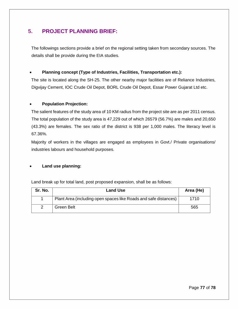
Page 77 of 78
5. PROJECT PLANNING BRIEF:
The followings sections provide a brief on the regional setting taken from secondary sources. The
details shall be provide during the EIA studies.
Planning concept (Type of Industries, Facilities, Transportation etc.):
The site is located along the SH-25. The other nearby major facilities are of Reliance Industries,
Digvijay Cement, IOC Crude Oil Depot, BORL Crude Oil Depot, Essar Power Gujarat Ltd etc.
Population Projection:
The salient features of the study area of 10 KM radius from the project site are as per 2011 census.
The total population of the study area is 47,229 out of which 26579 (56.7%) are males and 20,650
(43.3%) are females. The sex ratio of the district is 938 per 1,000 males. The literacy level is
67.36%.
Majority of workers in the villages are engaged as employees in Govt./ Private organisations/
industries labours and household purposes.
Land use planning:
Land break up for total land, post proposed expansion, shall be as follows:
Sr. No. Land Use Area (He)
1 Plant Area (including open spaces like Roads and safe distances) 1710
2 Green Belt 565

Page 78 of 78
6. REHABILITATION AND RESTTLEMENT (R&R) PLAN:
Since it is proposed to use the available land for the expansion project, no rehabilitation and
resettlement is envisaged.
7. PROJECT SCHEDULE AND COST ESTIMATES
Project Schedule:
The proposed expansion being a major expansion of Refining capacity and addition of
Petrochemical units shall be taken up sequentially and in phases. Some of the smaller units like
Alkylation, PRU etc which do not require significant enhancement of other supporting facilities shall
be started and completed first. Along with that initial activities for other larger units and utilities
shall also be taken up. Completion of all the expansion facilities is targeted by the year 2024.
Cost Estimates:
As mentioned under ‘Schedule”, the expansion shall be taken up in sequential phases and
accordingly the required investments shall be made. The total cost of this expansion project is
estimated to be USD 20 Billion.
8. ANALYSIS OF PROPOSAL:
This project will satisfy the domestic demand of Refinery and Petrochemical products. It will provide
direct/indirect employment to about 12,000-15,000 persons during the peak construction phase
and about 2,000-3,000 persons during operation.
The positive impacts also include indirect opportunities for local population. There will be indirect
development of small market for various aspects around the site.
Pre-feasibility study confirms viability of the project.