reference number: 14 title: feed manufacturing technology ... · american feed manufacturers...
TRANSCRIPT

AP-42 Section Number: 9.9.1
Reference Number: 14
Title: Feed Manufacturing Technology 111
American Feed Manufacturers Association, Arlington, VA
1985

Reference &
Feed Manufacturing
Technotogy
Repolt Sect. __ Reference __ '
I11 TECHNICAL EDITOR Robert R. McEllhiney
Professor Department of Grain Science and Industry
Kansas State University a
ASSOCIATE EDITORS Charles G. Olentine, Jr., Watt Publishing Company Raymond J. Lunemann, International Multifoods Corp. Jim Rempe, ACCO Feeds Division, Anderson, Clayton & Company Keith C. Behnke, Kansas State University Wallace D. Bees, Format Pharm-Tech. LaDell R. Swiden, Consultant Carl Stevens, Kansas Stete University Roy Schultz, Hubbard Millin Company John R. Pedersen, Kansas tl tate University Eugene F. Morneau, Cargill, Inc. K. v. Lensmeyer, Ralston Purina Company Robert R. McEllhiney, Kansas State University
... 111

Table of Contents Chapter Page SECTION I. INTRODUCTION TO THE FEED INDUSTRY 1
. . . . . . . . 2 1 History of the Formula Feed Industry . . . . . . . . . . . . . . . . . . . . . . . . . 9 2 The U.S. Formula Feed Industry Today . . . . . . . . . . . . . .
3 Feed Manufacturing: An International Perspective . . . . . . . . . . . . . . . . . . . 13
21 4 Plant Feasibility . . . . . . . . . . . . . . . . . . . . . . . . 22 5 Feed Plant Layout and Design . . . . . . . . . . . . . . . . . . 27 6 Construction of a Feed Plant . . . . . . . . . . . . . . . . . . . . . . . . 59 7 Pressurizing Feed Mills . . . . . . . . . . . . . . . . . . . . . . . . . . . . . . . 63
SECTION II. PLANT FEASIBILITY, DESIGN, AND CONSTRUCTION
SECTION Ill. BULK MATERIALS HANDLING AND STORAGE 65 8 Conveyors. 9 Bucket Elev
10 Bins . . . . . . . 11 Pneumatic Conveying . . . . . . . . . . . . . . . . . . . . . . . . . . . . . . . . . . . . . . . . . 93 12 Liquid Ingredients . . . . . . . . . . . . . . . . . . . . . . . . . . . . . . . . . . . . . . . 99
14 Receiving Cost Center . . . . . . . . . . . . . . . . . . . . . . . . . . . . . . 125 15 Material Processing Cost Center . . . . . . . 137
17 Pelleting Cost Center . . . . . . . . . . . . . . . . . . . . . . . . . . . . . . . . . . . . . 167 18 Blocking . . . . . . . . . . . . . . . . . . . 191 19 Extrusion Cooking Systems . . . . . . . . . . . . . . . . . . . . 195
21 Warehousing an . . . . . . . . . . . . . .
13 Dust Collecti
SECTION IV. MANUFACTURING OPERATIONS 123
16 Proportioning and Mixin
. . . . . . . . . . . . . . . . . . . . . . . . . . . .
20 Feed Packaging . . . . . . . . . . . . . . . . . . . . . . . . . .
22 Drying and Aeration of
SECTION V. SPECIALTY FEEDS 221 23 Production of . . . . . . . 222 24 Liquid Feeds . . . . . . . . . . . . . . . . . . . . . . . . . . . . . . . . 238 25 Microingredie . . . . . . . . . . . . . . . . . . . . . . . . . . . . . . . 242
26 Planning the Components of an Integrated System . . . . . . . . . . . 252
28 Justifying the System . . . . . . . . . . .
29 Maintenance Programs . . . . . . . . . . . . . . . . . . . . . . . . . . . . . . . . . . . . . . . . . 266
SECTION VI. COMPUTER SYSTEM APPLICATIONS 247
27 Implementing the Integrated System . . . . . . . . . . . . . . . . . . . . . . . . . . . . . . . 260 . . . . . . . . . . . . . . . . . . . . . . . . . . . . 262
265
30 Boiler Water Treatment . . . . . . . . . . . . . . . . . . . . . . . . . . . . . . . . . . . . . . . . . . . 273 31 32 Steam Traps 33 Compressed . . . . . . . 298 34 Plant Electric 35 Electric Motors . . . . . . . . . . . . . . . . . . . . . . . . . . . . . . . . . . . . . . . . 314 36 Special Purpose . . . . . . . . . . . . . . . . . . . . . . . . . . . . . . . .
SECTION VII. UTILITIES AND MAINTENANCE
Boilers and Associated Equipment . . .
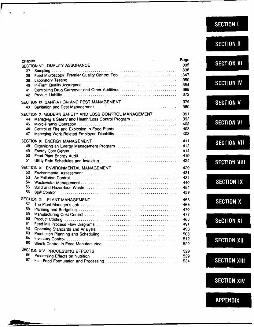
chapter SECTION VIII. QUALITY ASSURANCE
37 38 39 40 41
Sampling . . . . . . . . . . . . . . . . . . . . . . . . Feed Microscopy: Premier Quality Co Laboratory Testing . , . . . . . . . . . . . . . . . . . . . . . In-Plant Quality Assurance , , . . . . . . . . . . . . . . . . . . . . . . . . . . . . . . . . . . . . . . . . . . . . Controlling Drug Carryover and Other Additives . . . . . . . . . . . . . . . . . . . . . . . . . . .
42 Product Liability . . . . . . ..................................... SECTION tX.-SANITATION AND PEST MANAGEMENT
43 Sanitation and Pest Management.. . . .:. . . . . . . . . . . . . . . . . . . . . . . . . . . . . . . . . .
44 Managing a Safety and Health/Loss Control Program . . . . . . . . . . . . . . . . . . . . . . 45 Micro-Premix Operation .................... ......................... 46 Control of Fire and Explo n in Feed Plants.. . . . . . . . . . . . . . . . . . . . . . . . . . . . .
SECTION XI. ENERGY MANAGEMENT
SECTION X. MODERN SAFETY AND LOSS CONTROL MANAGEMENT
47 Managing Work Related Employee Disability . . . . . . . . . . . . . . . . .
48 Organizing an Energy Management Program ......................... 49 Energy Cost Center.. , . . . . . . . 50 Feed Plant Energy Audit . . . . . . . . . . . . . . 51 Utility Rate Schedules and lnvoi
SECTION XII. ENVIRONMENTAL MANAGEMENT 52 Environmental Assessment . . . . . . . . . . . . . . . . 53 Air Pollution Control . , , . . . . , 54 Wastewater Management . . . . . . . . . . . . . . . . . . . . . . . . . . . . . 55 Solid and Hazardous Waste , . . . . . , , . . . . . . . . . . . . . . . . . . . . . . . . . . . . . . . . . 56 Spill Control . , , . . ' . . . . . . . . . . . . . . . . . . . . . . . . . . . . . . . . . . . . . .
57 The Plant Manager's Job . . . , , . . . . . . . . . . . . . . . . . . . . . . . . . . . . . . . . . . . . . 58 Planning and Budgeting . 59 Manufacturing Cost Contr
61 Feed Mill Proces 62 Operating Standards and Analysis . . . 63 Production Planning and Scheduling . . . . . . . . . . . . . 64 Inventory Control , , , , . . . . , , , . . . 65 Shrink Control in Feed Manufacturing . . . . . . . . . . . . . . . . . . . . . . . . . . . . . . . . . . . .
66 Processing Effects on Nutrition . . . . . . . . . . . . . . . . . . . . . . . . . . . . . . . . . . . . . . . . . . 67 Fish Food Formulation and Processing . . . . . . . . . . . . . . . . . . . . . . . . . . . . . . . . . . .
. . . . . . . .
SECTION XIII. PLANT MANAGEMENT
60 Product Costing . . . . . . . . . . . . . . . . . . . . . . . . . . . . . .
XIV. PROCESSING EFFECTS
Page 335 336 .347 350 354 369 372
379 380
391 392 402 403 408
41 1 412 41 4 41 9 424
429 43 1 434 440 454 459
463 465 470 477 486 491 498 508 51 2 522
529 529 534

APPENDIX Page A . B . C . D . E . F . G . H . I . J . K . L . M . N . 0 . P . Q .
....................... . . . . . . . . . . . . . . . . . . . . . . . . . . . . . Plant Feasibility . Site Visit Check List . . . . . . . . . . . . . . . . . . . . . . . . . . . . . . . . . . Determining and Expressing Particle Size
Properties of Saturated Steam and Water Physical Properties of Feed Ingredients . . . . . . . . . . . . . . . . . . . . . . . . . . . . . . . . . . Wafers. Pellets. and Crumbles . . . . . . . . . . . . . . . . . . . . . . . . . . . . . . . . . . . . . . . . . .
Package Weight Control . . . . . . . . . . . . . . . . . . . . . . . . . . . . . . . . . . . . . . . . . . . . . . . .
. . . Test Procedure for Solids . Mixing Equipmen
. . . . .
A Procedure for Estimating Degree of Gelatinizations of Cooked Grains . . . . . .
Typical Sewer Use Ordinance Lim Calculation of Stormwater Runoff Characteristics of Hazardous Waste General Construction Specificatio Electrical Data . . . . . . . . . . . . . . . . Basic Statistical Concepts . . . . . . Formulas for Geometric Figures . Conversion Factors . . . . . . . . . . . . .
541 546 549 552 556 558 563 566 567 569 570 570 571 585 587 595 598
FOR YOUR INFORMATION Feed Plant Short Courses . . . . . . . . . . . . . . . . . . . . . . . . . . . . . . . . . . . . . . . . . . . . . . . . . . . . . . . . 20 Truck Management . . . . . . . . . . . . . . . . . . . . . . . . . . . . . . . . . . . . . . . . . . . . . . . . . . . . . . . . . . . . . 166 Feed Science and Management at KSU . . . . . . . . . . . . . . . . . . . . . . . . . . . . . . . . . . . . . . . . . . . 246 INDEX . . . . . . . . . . . . . . . . . . . . . . . . . . . . . . . . . . . . . . . . . . . . . . . . . . . . . . . . . . . . . . . . . . . . . . . . 605
I .
Chapter 2
1.
The U.S. Formula Feed Industry Today
Wayne Anderson Feedstuffs Senior Editor
The one sure statement that can be made about the formula feed industry in the U.S. today is that it will not be the same tomorrow. Change has always been a pati of feed manufacturing. a:, with niost other industries. and that is as true now as i t has ever been. New customers. new markets. new technology. and different economic conditions all play roles in causing that change.
The U.S, feed industry of the 1980s is basically a mature industry. Overall. per capita consumption of animal products has generally plateaued and population growth in the U.S. has sta- bilized at an annual rate of about I & . Livestock and poultry producers continue to decline in numbers while increasing in u n i t size. The growth of various forms of venical integration. contrac- tual arrangements and. more recently. on-farm feed mixing. all have combined with fewer customers to cause a decline in the nuniherof manufacturers and dealers in the traditional (hrmula feed industry in the U.S.
Defining the Industry When doing any survey of the feed industry. i t is necessary
to set up definable parameters to which the feed ntanuiacturers and their products can be compared. The United States Depanment of Agriculture has periodically conducted surveys of the feed indus- try. In those studies the follou,ing definitions fur feed manufactur- ing haw been used: b
e
e
e
Fwd.!n;ll;q rsroDlihmctir is usually a slalionary mill opera- tion st a single location together with any mobile niills hased at that location. I'riiiuir~/cki/ niiintfitcruriq is the processing ;ind mixing of individual feed ingredients. sometimes with the addition of a premix at a rate of less than 100 pounds per ton of linished Iced. S c ~ . o r i i l ~ t r \ . ~ r d s ~ r t ~ ~ r i f ~ ~ c r u r i ~ ~ g is the processing and mixing of m e or more ingredients with formula feed supplements. SupplemenLs are usually used at a rate of304 pounds or more pcr ton of finished feed. dependins on the protein conient of the supplement and percentage of protein desired in the linished feed. C I I ~ ~ I I I g r i t i d i q tind nii.rin8 is grinding customer-owned feed ingredients and usually mixing supplements with them. Mainly. this is a service provided to Sarmers feeding their own animals.
Onc 0 1 the iiiaior nrohlems involved in evaluatine the Dro-
mately ?on pounds o r more per ton to make a balanced ration.
0 B ~ I S P m;.wslwper cniicciiirules differ from supplements in that they contain only pan of the animal's protein re- quirements. I t is added with grain and other high prolein ingredients at the rate of 100 pounds (or more) per tun to make a balanced ration.
0 Preriiirrs are formulations of one or more rnicroingredients. such as vitamins. minerals. trace minerals. or drugs mixed with a carrier ingredient. They do not contain any significant amount of protein. A premix is usually added at a rate of less than 100 pounds per ton with grain and other protein in- gredients to make a balanced ration for nonruminant ani- mals. For beef. i t may be mixed (or top-dressed) with grains andlor roughages to make a complete ration.
The feed industry has traditionally been an ouilet for a number of mill by-products and oil extraction products. Table 2-1 illustvales how cenain by-product ingredients have increased in usaseoverthepast ISyears. Compiled by USDA.thetableshou,sa dramatic increase in demand for soybean meal while other protein ingredients have either held steady or have declined. Additionally. the quantity of high-protein feeds consumed by livestock and poultry has increased greatly.
Corn is the primary grain used in animal feeds in the U . S . . comprising ahout 75%> of the Seed grain market for domestic consumption (Table 2-21, In terms of corn equivalents. feed con- sumed by livestock and poultry showed little growth in the early 1980's: in Pact. consumption has not grown to a great degree over the last IS years (Table 2-3) .
- . ductiw figures of t h e industry i b a lack of clear definition of ' Y W 01 lceds. However. the American Feed Manulacturers As- s o c i a h has defined types of feeds in the following manner:
Cwl/llc:cficd contains a proper balance uf nutrirnis and is intended tu he the sole ration for nonruminant rations. h q h a g e is normally excluded from ccrmplete feed. How- w r . for ruminant aninlak some portion the roughage needs nlay he included in the complete commercial ration. ~ ~ ~ / ~ ~ ~ I ~ ~ ~ i i ~ ~ i ~ ~ s l ~ ~ ~ ~ ~ ~ ~ ~ ~ ~ ~ r r ~ ~ ~ ~ . ~ contain the proper balance of pro- tein. yitaniins. minerals. trace minerals, and additives. It is added with grain andlor roughqe at Ihc rille of approxi-
Y 2 . THE U.S. FORMULA FEED INDUSTRY TODAY
Changes in the Industry The commercial feed industry. which ranks anions the top
25 industries in the U.S.. currently iscomposed ofanestinlared 400 companies. with about 3.ooO primary Seed manuPacturing plants sewing another 10.000 secondary manuPacturing plants. An esti- mated 7O.M)O persons are employed in primary feed nianufacturing facilities and anotlrrr 55.000 in secondary manufacturinf plantr. Approximately 20.000 dealers distribute feed products tu pro- ducers. accounting for about 60% of relail feed sales. The remain- ing retail Iced volume is sold directly to producers by Seed organ- izations. including thilt suld directly to large producers who. in effect. become dealers themselves.
The changes nientiuned above h w e brought new entrants into the feed supply business. as wel l as new product and service opportunities fur existing feed manuPacturin? companies and desl- ers. Livestock and puultn producers in the U.S. arc being ofl'ered an ever-widening array of low-inclusion prixlucts such as preniises and basemixes. as wll as specific ingredients. tu be mihed wiih their own grains and protein products. New and #more refined on-farni mixingrquipment isavailable. as well as nutritionconsult- ing services.
Both traditional feed manufacturers and new suppliers to producers are hecoming more attuned to working with larger. nmrc
20 Ton/Hour General Purpose Feed Plant Fred S. Stivers
The T.E. Slivers Organization. Inc
This plant i s designed for production o f a general line of livestock feeds. Various options exist l o tailor the plant to suit a particular location and regional market. The design provides for truck and rail receipt o f ingredients. a hatch mixing system. a pelleting system. grinding. crimping or dry rolling. a textured or molasses mixing system, and bagged and hulk handling for finished feed.
I t i s expected that most feed plants using this hasic design would have grinding. hatch mixing. and pelleting systems. Other systems and equipment could he tailored to suit particular needs. For example. the plant could be an all-bulk facility for manu- facturing mainly swine and poultry pellets and mash feeds. In that case. the grain crimping. textured mixing. and sacking systems could he deleted. As another alternative. the plant could he de- signed for mure texwred dairy feed. For that approach. a steamer and cooler could he added to the grain crimping system to provide for steam rolled grains. The molasses feed mixing system could be modified for loading bulk textured feed direct to trucks.
Basic design criteria are established as follows:
Re c e i v i n p Grinding ( I mill @ 125 hp) Mixinc 1 2 ion mixer1 - Crimpins Pclletine (I mill (ir 200 hn) Ovcral l Average Production
Tons Per H O W
7s 1.5 24 S
20 1s-20
The plant i s expected to generally operate one shift. 5 days per week. Production would be as follows:
TonsIHour 20 TonslDay I60 TonsiWeek 800 TonsiYear 40.000
Receiving I t i s assumed that approximately 90'3% of the ingredients wil l
he receked in bulk ahoui equally split between truck and rail. A handling rate of75 tonsper hourwasselected. That wi l l he
abvut 3% times the average production rate. which i s more than adequate. However. that rate wi l l provide for unloading 20- to 22-ton truck loads in about 20 niinutes and 90-ton rail cars in about I V? hours with some time allowance for moving vehicles.
I t is assumed that only rail hopper cars wil l he handled. A single pit to accummodate one hopper car i s provided. The car wil l need to be moved aseach hopper isemptied. For this sizeofplant. i t is not believed that a longitudinal conveyor. such that a rail car could he unloaded in one spot. could he justified.
A truck unloading grate. 10 feet wide by 6 feet long. provides for hopper bottom or self-dumping trucks. For this size operation. a truck dumper could not he justified. Also. some Ilexihility usually exists for specifyingthe typeof trucks that can he rcceivcd.
Incoming ingredient trucks wil l he weighed on the truck scale that i s also used for outbound trucks.
Two feeder con\'eyors are pro\,ided for the truck and ra i l receiving pits. The conveyors discharge into a common gathering
chute above the receiving elevator inlet. A t that point. a plate magnet i s provided in the chute to remove ferrous material ahead of the elevator. The receiving elevator carries material to the topof the plant where i t discharges either to a receiving scalper and to the overhead bins. or to the conveyor serving the outside siorage. The scalper would normally have about a I-inch mesh screen. Al l gravity flow would be used for distribution to the plant's bins. A conveyor i s used for transfer to the outside storage area via a distributing turnhead.
As an uption to this layout. the receiving scalper could be arranged to scalp ingredients going to both the plant and outside storage bins.
Grinding Corn, milo. and alfalfa pellets are to be ground with a rate of
about 15 tons per hour through a '%-inch screen. Actual usage of 60% ground materials wil l result in an average requirement of I 2 tons per hour. A 125 hp. full-circle hammermill i s selected. For even flow to the plant. a surge bin and feeder are located above the hammermill.
A by-pass valve i s located ahead of the surge bin. This will permil the iransferof corn or mi lo to the working bins forcracking.
20 TONiHOUR GENERAL PURPOSE FEED PLANT Equipment Legend
1. Rail Receiving Conveyor 2. Truck Receiving Conveyor 3. Magnet 4. Receiving Elevator 5. Tw-Way Valve 6. Transler Conveyor 7. Turnhead Distributor 8. Corn Storage Bin 9. Milo Storage Bin
10. Alfalfa Storage Bin 11. Receiving Scalper 12. Receiving Distributor 13. Storage Bin Feeders 14. Grain Transfer Conveyor 15. Grain Transteter Elevator 16. Two-way Valve 17. Surge Bin and Level Control 18. Hammarmill Feeder 19. Hammermill 20. Hammarmlii Discharge Conveyor 21. Hammermill Air System 22. Grinding Elevator 23. Grtnding DlstribUlor 24. Pneumatic Receiving Piper 25. Grain Scrwner (with Aspiration) 26. Two-way Valve 27. Grain Crimper 28. Crimped Grain Eie~ator 29. Transfer Conveyor 30. Two-way Valve 31. Ingredient Bin Screw Feeders 32. Maln ingredient Scale 33. Mineral Ingredient Scale
34. Scale Air Gate 35. Scale Air Gale 36. Batch Mixer 37. svrge Bin 38. Surge Conveyor 39. Mixing Elevator 40. Magnet 41. Mash Cleaner 42. Overs Regrinder 43. Mash Distributor 44. Mash Transfer Conveyoi 45. Mash Distributor 46. Slide Gales 47. Surge Bin 48. Pellet Mitt 49. Horizontal Cooler 50. By-Pass 51. Crumble Roils 52. Cooler Air System 53. Pellet Elevator 54. Pellet Screener 55. Two-way Valves 56. Pellet Distributor No. 1 57. Pellet Distributor No. 2 56. Air Slide Gales
60. Truck Scale 61. Bin Feeders 62. Molasses Mixer 63. Surge Hopper 64. Feed Bagger 65. Sewing Head 66. Sewing Bell
59. Collecting Hopper
36 SECTION II. PLANT FEASIBILITY. DESIGN, AND CONSTRUCTION

I
5. FEED PUNT UYOUT AND DESIGhi
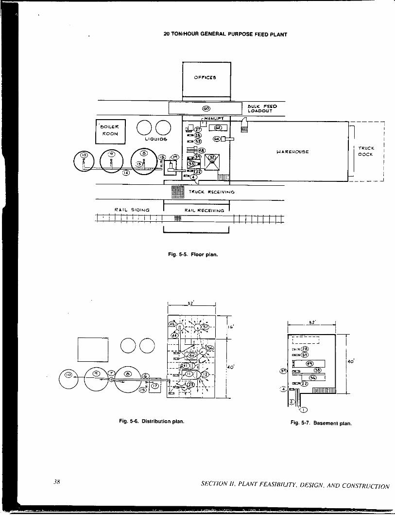
Fig. 5-6. Distribution plan.
1-17
Fig. 5-7. Basement plan.
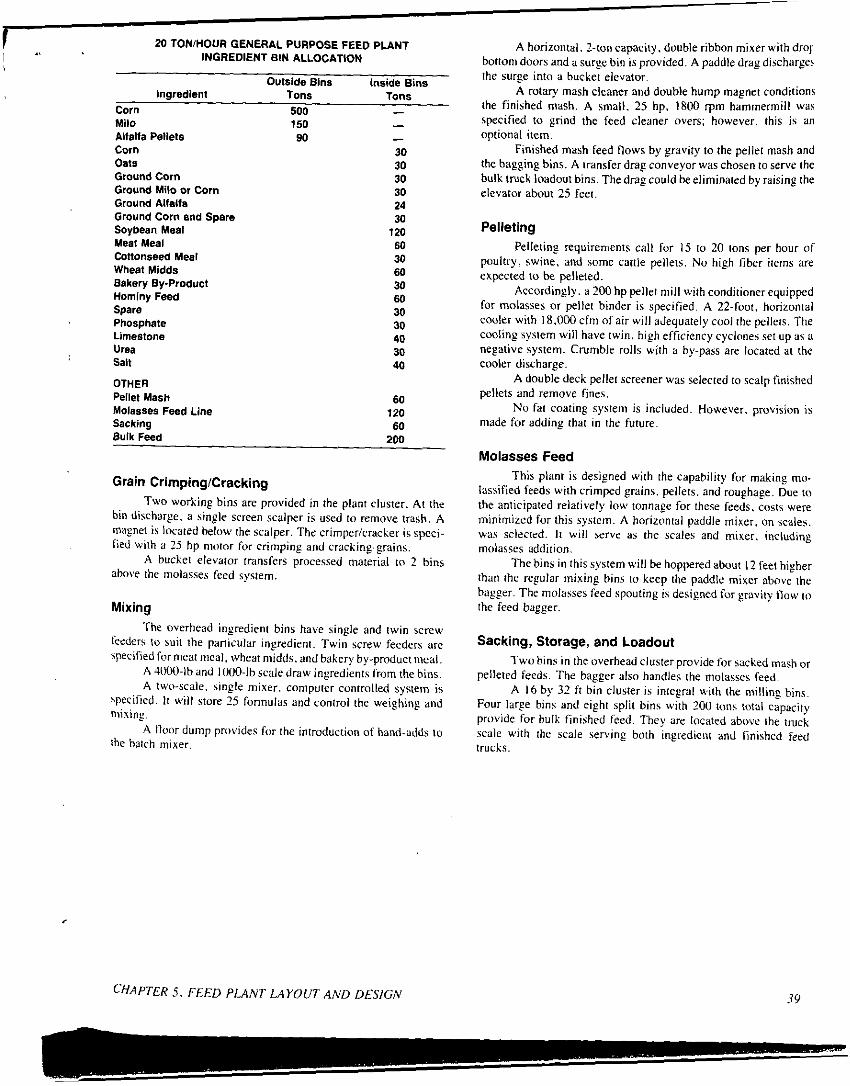
20 TON/HOUR GENERAL PURPOSE FEED P U N T INGREDIENT BIN ALLOCATION
1 I I'
Outside Blns Inside Bins Ingredient Tons Tons
Corn 500 - Milo 150 - Altalta Pellets 90 - Corn 30 Oats 30 Ground Corn 30 Ground Milo or Corn 30
Ground Corn and Spare 30
Meat Meal 60 Cottonseed Meal 30 Wheat Midds 60 Bakery By-Product 30 Hominy Feed 60 Spare 30 Phosphate 30
Urea 30
Ground Alfalfa 24
Soybean Meal 120
Limestone 40
Salt 40
OTHER Pellet Mash 60
Sacking 60 Molasses Feed Line 120
Bulk Feed 200
Grain CrirnpingCracking Tu,o working hins are provided in the plant cluster. A t the
bin discharge. a single screen scalper i s used to remove trash. A magnet i s located below the scalper. The crimpericracker i s speci- fied with a ?5 hp nmor for crimping and cracking grains.
A bucket elevator transfers processed material to 2 bins above the molasses feed system.
Mixing The overhead ingredient bins have single and twin screw
feeders to suit the panicular ingredient. Twin screw feeders are specified formeat meal. wheat midds. and bakery by-product meal.
A 4Ol)O-lh and 1000-Ib scale draw ingredients from the hins. A two-scale. single mixer. computer controlled system is
iprciiied. I t wi l l store 2.5 formulas and control the weighing and mixiny.
A flnur dump provides for the introduction of hand-adds to the batch mixer.
A horizontal. 2-ton capacity. double ribbon mixer with dror bottom doors and a surge bin i s provided. A paddle drag discharge? the surge into a bucket elevator.
A rotary mash cleaner and double hump magnet conditions the finished mash. A small. 25 hp, 1800 rpm hammermill was specified to grind the feed cleaner overs; however, this i s an optional item.
Finished mash feed flows by gravity to the pellet mash and the bagging bins. A transfer drag conveyor was chosen to serve the hulk truck loadout bins. The drag could be eliminated by raising the elevator about 25 feet.
Pelleting Pelletin@ requirements call for 15 to 20 tons per hour of
poultry. swine. and some cattle pellets. No high fiber items are expected to be pelleted.
Accordingly. a 200 hp pellet mi l l with conditioner equipped for molasses or pellet hinder i s specified. A 22-foot. horizontal cooler with 18.000 cfm of air wi l l aJequately cool the pellets. The cooling system will have twin. high efficiency cyclones set up as a negative system. Crumble rolls with a by-pass are located at the cooler discharge.
A double deck pellet screener was selected to scalp finished pellets and remove fines.
No fat coating system is included. However. provision i s made for adding that in the future.
Molasses Feed This plant i s designed with the capability for making mo-
lassified feeds with crimped grains. pellets. and roughage. Due to the anticipated relatively IOU' tonnage for these feeds. costs were minimized for this system. A horizontal paddle mixer. on SCdkS. was selected. I t wil l serve as the scales and mixer, including molasses addition.
The bins in this system will be hoppered about I2 feet higher than the regular mixing bins to keep the paddle mixer above the bagger. The molasses feed spouting i s designed for gravity flow to the feed bagger.
Sacking, Storage, and Loadout T w o bins i n the overhead cluster provide for sacked mash or
pelleted feeds. The bagger also handles the molasses feed. A 16 by 32 ft bin cluster i s integnl with the milling hins.
Four large bins and eight split bins ujith 200 tons toial capacity provide for bulk finished feed. They arc located above the truck scale uaith the scale serving both ingredient and finished feed trucks.
39 CHAPTER 5 . FEED PLANT LAYOUT AND DESIGN

50 Ton/Hour Full Line Feed Plant W. Gary Wlnsen, PE
The T.E. Stlvers Organization. Inc.
This plant design i s based on an overall average production of SO tons per hour. Operating on two shifts, the plant wi l l produce around 200,000 tons of general line feeds annually. Specifically, the plant is geared for utilizing a relatively wide range of in- gredients and by-products to produce mash, pellets. crumbles. steam rolled and dry cracked grains, scratch feeds. and textured ruminant feeds in both bagged and hulk forms.
The following projections are provided for the design criteria.
Type Ot Feed X ot Total ~
Textured: Pellets 15 Grains 15 Other 5
35 Meal and Mash 10 Beef and Dairy Pellets 25 Swine and Poultry Pellets 25 Scratch and Miscellaneous 5 -
65 100
From the above projections. the following i s tabulated
% Pelleted 65 Rolled 15
20 100
Type -
Non-Pelleted and Non-Rolled - Bulk and hag receipts and shipments have been stipulated as follows:
Finished Ingredient (%) Product (36)
Rail 60 10 Bulk
Truck 36 - 96
Bag Rail 2 Truck 2
50 - 60
5 35
Traffic Patterns and General Arrangement Bulk and bagged ingredients via.both rail and truck are to be
handled. Outbound feed i s to he shipped bulk and bagged via both truck and rail. The plant capacity requires two rail sidings and two truck driveways.
Based on the above data. one rail siding needs to be adjacent to the plant warehouse. Also. i t i s better to have rail sidings adjacent to each other. I t i s also desirable to a w i d trucks having to cross the rail sidings. To suit the general requirements. the rail and truck is split with one on each side of the plant warehouse. The rail siding i s
located on the "receiving" side and the truck driveways on the "shipping" side. That arrangement meets the basic criteria and provides workable and efficient traffic patterns.
Receiving A 7?-fOot long by 360-1011 capacity. AREA design railroad
track scale provides for the weighing of incoming rail receipts. By switching. outbound hulk feed in rail cars and boxcars can also be weighed. The scale wi l l have eight. 100.000-lb compression load cells and a 400.000-lb by 20-lb digital instrument. The 360-1011 capacity and AREA design should meet most railroad require-
however. that should he verified with the specific railroad ng a panicular plant. The scale has a concrete "floating"
deck with a 40-foot grating section belu'een the rails. A ra i l receiving conveyor also runs beneath the grating section. That allows for unloading hopper cars with one spotting.
Although i t i s being used lebs and less by most plants. boxcar unloading i s provided. I t utilizes a ramp and boxcar height dock with a small front end ladder. For this panicular design. the boxcar unloading is provided for handling such by-products as cottonseed hulls.
To provide flexibility in local ingredient purchases. a hy- draulic truck dumper is specified. Due to relative costs and flexibil- ity. the dumper is specified to be on load cells for weighing trucked ingredients. An alternative would he to use the truck scale on the luad-out drive. The dumperiscale wil l he 70 I t long and have a 70-1011 capacity to provide for foreseeable truck sizes at the loca- tion. Even larger scales may he required in some locations.
To accommodate the dumping of approximately ??-ton loads. a 1000-cubic Soot receiving hopper i s used.
The truck and rail scales are specified to have data transfer circuitry fur automatically *ending the net weight oCa receipt. along with a manually entered product identification code. to the mi l l computer contrd system. That provides for the inventory system and a computer record of receipts.
Rail receiving has a transfer conveyor for carrying material5 to the r a i l rccciving clcvator. For truck receiving. the same con- veyor is used as a feeder and fur transfer to the truck receiving clewtor. Due to the by-products being handled. durability needs. and fecder requircmcnts. screw type con\'eyors were selected for receiving.
Both trucks and rail receiving conveyors discharge into double doped magnetic chutes jus1 ahead of the elevator boot inlets. This utilizes a minimum of headrooni and prwidcs for the reinuval o f ferrous meta l ahcad of the e l e w t o r less.
Thecapacilyofeachofthetrucl,andrailsysremsissetat I 3 tons per hour o n 40 Ibs per cubic foot material. That is 1% times the averilgeproduction rate. Also. i t is preferable torecei\,eonlyduring the day shift. The ele\,ators u,ill haw to bc used fixtransfer of about ?0'X of the ingredients fronl outside storage to owrhcad mill uorkingstura?c. To iiiect those requirements. the 125 tuns per hour rate was selected. Provision could he ni:ide lor havinp the tu,,)
system!. use the two elevators interch;inyhly. It wuuld require niore basement depth and u'ould he rclativcly expensive.
40 SECTION 11. PLANT F E m n i L r r ~ . DESIGN. A N D CONSTRUCTION

Ingredient Distribution The truck and rail receiving legs are located near the hub of
the plant and outside storage bins. For this particular plant. in- gredients must come to a central location and then be distributed. Accordingly. the centralizing is handled most efficiently hy gather- ingonthelowerlevelandthenutilizinggravityflowonthetopside.
Everything being equal. it is generally more desirable to maximize gravity flow over conveyed flow. However. as the horizontal configuration expands. a trede-olf develops between elevator height and spouting runs versus conveying. For the design of this receiving/distribution system. the compromise selected uses all gravity flow to the plant and at the two outside storage clusters. Conveying is used for distribution 10 the two outside storage clusters. Also. all flow is positively controlled through single discharge conveyors and turnhead distributors. That is generally preferred over multiple discharge conveyors lor plants handling nonfree-flowing ingredients.
To provide the required flexibility for receiving and transfer to the plant. dual spouted turnheads are specified. These have two inlet spouts and one set of outlet spouts. That provides transfer to any bin by either system or both systems to the same bin siniul- Uneously. High level indicators provide an alarm and shut-down if a bin is overfilled.
This plant design. like most modem feed plants. requires provision for handling pneumatic discharge trucks (minerals) and
liquid hauling trucks. Ample parking is provided with the two truck driveways forthose purposes. Pneumatic lines from ground level to the bin deck are provided.
Ingredient Bins Table 5-1 shows the ingredients to be used along with the
projected usage and storage provided. I n the initial design con- siderations. the ingredients to be used and their daily usage were determined. The desired storage and the size of the receipt were also determined.lThe desired storage and receipt sizes were coni- pared and the bin requirements determined accordingly: i.e.. the bin(s) provide the minimum of desired storage of 1%. times the incoming load size.
An overhead bin cluster is generally the most desirahlu type of ingredient Storage. I t maximizes gravity flow into the ni ixins and other systems. On the other hand. outside ground level storage is less expensive. For a plant of this size and with the wide ;!nay of ingredienrs. a trade-off develops between these two approaches. A combination was chosen that utilizes both types of stomge. A working bin for ingredients in outside storage is provided in the overhead cluster. Those ingredients can be transferred from outside to overhead storage through either the truck or rail receiving system. Also. bins for all major grains and products to be ground were located outside.
Table 5 1 . INGREDIENT USAGE AND STORAGE OF 50 TONIHOUR FULL LINE PLANT.
Usage Max. Min. Min.l'l % Tons Load 1% x Days Storage Storage Outside"' Of Per Size Load Storage Requirid Provicied Storage
Tons Days Utilized Total Day (Tons) Size Desired Tons Ingredient Corn 28 224 Milo 3 24 Barley 3.2 25.6 75 Oats 4 32 40
Corn Screenings 6.2 49.6 75
Brewers Grains 2 16 Malt Hulls 2 16 40 Alfalfa Pellets 1.5 12 70
95 143 7 1568 1650 7 X
90 135 10 240 280 12 X
113 10 256 250 10 X 60 7 224 200 6 X
135 5 135 160 16 X 113 7 350 450 9 X 113 4 113 125 8 X
60 90 5 90 120 8 X 60 4 64 70 4 X
105 5 105 180 15 X 6 8 5 480 450 5 X
Wheat 2 16 90
Dust Pellets 2 , 16 75
Wheat Midds 12 96 45 Bakery By-Product 4 cononseed HUIIS 3 Beet Pulp 0.5 4 Soybean Meal - 48 11 88
32 22 33 3 96 120 4 24 40 60 5 120 100 4
90 135 7 616 610 7 X
80 120 5 120 120 5 75 113 5 120 120 5 22 33 4 64 75 5
60 22 7 33 40 10
Soybean Meal - 44 3 24 Cononseed Meal 3 24 Meat Meal 2 16
Limestone 0.4 Phosphate 0.8 6.4
120 10 160 125 8 X Corn Gluten Meal 2 16 80
Salt 0.1 0.8 22
3.2 22 33 5 33 40 13 90 135 5 135 140 22
33 5 33 35 44 _ _ 2.4 22 33 5 33 30 13 Urea 0.3
5490 7 avg. - - Sub-Total 96.0 768 - - 3.6 28.8 22 33 5 144 150 5
Liquids Micros (I Hand-Adds n d I, ~ - - - - - - - - ".C -. . ~.
I - - - 5640 7avg. - Total 100.0 800.0 - (1) bctaled by eilher 1 '/s load size or rnm d a w storaae deslred whlchever IS greater
Outside storage uthzed. either because of cheaper storage or because material IS to be ground
J / CHAPTER 5. FEED PLANT LAYOUT ANI1 DESIGN
A
50 TON/HOUR GENERAL PURPOSE FEED PLANT
, I
42
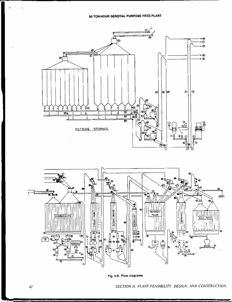
Fig. 5-8. Flow diagrams.
SECTION II. PLANT FEASIBILITY. DESIGN. AND COh'STUUCTlOh'

50 TON/HOUR GENERAL PURPOSE FEED PLANT Equlpment Legend
1. Rail Scale 2. Truck Dumper and Scale 3. Front End Unloader 4. Rail Receiving Feeder 5. Box Car Receiving Feeder 6. Truck Receiving Feeder 7. Rail Transfer Conveyor 8. Receiving Magnets 9. Rail Receiving Elevator
10. Truck Receiving Elevator 11. Rail Receiving Scalper 12. Truck Receiving Scalper 13. Two-way Valves 14. Mill Receiving Distributor No. 1 (Dual Spout) 15. Transfer Conveyor 16. Mill Receiving Distributor No. 2 17. Rail Distribution Conveyor No. 1 18. Truck Distribution Conveyor No. 1 19. Outside Storage Distributor No. 1 (Dual Spout) 20. Rail Distribution Conveyor No. 2 21. Truck Distribution Conveyor No. 2 22. Outside Storage Distributor NO. 2 (Dual Spout) 23. Outside Storage Bin Feeders 24. Grinding Transfer Conveyor No. 1 25. Grinding Transfer Conveyor No. 2 26. Grain (L Ingredient Transfer Conveyoi 27. Grinding Transfer Elevators 28. Two-way Valves 29. Level Indicators 30. Hammermill Feeders 31. Hammermills 32. Hammermills’ Air Assist System 33. Grinding Elevators 34. Grinding Distribution Conveyors 35. Grinding Distributor (Dual Spout) 36. Ingredient Bin Feeders 37. Major Batching Scale - 5 Tons 38. Minor Batching Scale - 1 Ton 39. Air Slide Gates 40. Two-way Valves 41. Microingredient System 42. Microingredient Transfer System 43. Computer Based Control System 44. Batch Mixer - 5 Tons 45. Mineral Mixer - 3 Tons 46. Surge Hoppers 47. Surge Discharge Conveyors 48. Mash Elevator 49. Rotary Feed Cleaner 50. Mash Distributor 51. Mash Loadout Conveyor 52. Air Slide Gales 53. Pellet Mills 54. Horizontal Pellet Coolers
55. Cooler Air Systems 56. Crumbler Rolls 57. Pellet Elevators 58. Pellet Screeners 59. Screener Two-way Valves 60. Pellet Distributors No. 1 and No. 2 61. Fat Coater Elevator 62. Fat Coater Surge and Level Controls 63. Fat Coater Feeder and Blender 64. Two-way Valve 65. Rail Loadoul Conveyor 66. Pellet Distributor No. 3 (Dual Spout) 67. Bulk Feed Distributor NO. 1 (Dual Spout) 68. Bulk Feed Distrlbutor No. 2 69. Grain Transfer Elevator and Conveyor 70. Surge Hopper and Level Indicators 71. Grain Cleaner (3 decks) 72. Clean Grain Distributor 73. Slide Gates 74. Graln Chest Steamers 75. Roller Mills 76. Horizontal Rolled Grain Coolers 77. Cooler Air Systems 78. Two-way Valve 79. Dry Grain Roller Mill 80. Cracked and Rolled Grain Elevators 81. Three-way Valve 82. Rolled Grain Distributor (Dual Spout) 83. Slide Gates 84. Volumetric Scratch Feeders 85. Test Valves 86. Blending Conveyor 07. Scratch Grain Elevator 88. Two-way Valve 89. Textured Bin Feeders 90. Textured Batch Scale - 3 Tons 91. Double Slide Air Gate 92. Microsystem 93. Textured Elevator 94. Screener (2 Screens) 95. Two-way Valve 96. Molasses Mixer 97. Two-way Valve 98. Bet1 Conveyor 99. Air Slide Gates
100. Surge Hoppers 101. Molasses Feed Bagger 102. PellelSiMash Feed Bagger 103. Sewing Heads 104. Sewing Belts 105. Bag Belt System 106. Air Slide Gates 107. Truck Scale 108. Pneumatic Receiving (Pipes and Filter) 109. Freight Elevator
Equipment Not Shown High and Low Level Indicators Liquid Handling Systems Dust Control Equipment Boiler and Steam Equipment
43 CHAPTER s. FEED PLANS LAYOUT AND DESIGN

50 TONiHOUR GENERAL PURPOSE FEED PLANT
Fig. 5-9. Mill and outside storage, top view.
SECTION II. PLANT FEASIBILITY. DESIGN. A N D CONSTRUCTION

50 TONlHOUR GENERAL PURPOSE FEED PLANT
i
\ L
k"
Fig. 5-10. Mill and outside storage. side view.
7-
45 CHAPTER s. FEED PLANT LAYOUT AND DESIGN
I

50 TON/HOUR GENERAL PURPOSE FEED PLANT
Fig. 5-11. Receiving and toadout.
Grinding From the ingredient usage dard. the ingredients to he ground
amount to about 22 tons per hour. Some ingredients to be ground are by-products and relatively fibrous in nature. Also. a11 iiiaterials are to be fine ground for pelleting and coarse ground for mash feeds.
Based on those requirements. two independent grinding systems are specified. The hammermills will be full circle. top feed with air-assist systems. 125 hp. 1800 rpm motors are specified. Rotor diameter will provide about 2 I.000 feet per minute peri- pheral speed with the 1800 rpm motors. Thai usill minimize vibra- tion. noise. and maintenance and provide satisfactory grinding action. The air-assist systems with about 1500 cfm each will
improve capacity. panicularly with the lower density by-products. and help control dust emissions.
Bin discharge feeders with manually adjustable. variable pitch sheave drives are provided. A transfer con\'eyor conveys material to il shon height bucket elevator. The eleYator discharges into a surge hopper with high and low level indicators. Beneath the surge, a variable speed pocket feeder feeds the hammermill. The feeder speed will he remotely controlled to suit either hammermill motor load or through-put capacity. whichever controls. The surge hopper and level indicator system will keep material ahead of the feeder. The manually adjustable bin feeders can be varied periodi- cally to suit conditions.
46 SECTION 11. PLANT FEASIBILIT'Y. DESIGN. AND COhSTRUCTION

In light of energy requirements and costs and for reducing shrink losses. a mechanical handling system with conveyor and bucket elevator was selected for transfer to the overhead working bins in the plant. For this particular design. a conveyor i s used across the top of the bin deck. A n option would be to increase the height o f the grinding elevator and utilize gravity flow to eliminate the conveyor. Again, as in the case of receiving. a dual spouted tumhead distributor i s specified lo meet flexibility requirements.
This plant layout has the hammermills in the skirted area below one of the outside storage bins. Another approach would he lo locate the hammermills in the basement. The rationale for the design provided was to isolate the hammermills to reduce noise levels in the working areas of the plant. to reduce the hazards of fire and explosion. and to provide easy accessibility to the equipment.
Grain Cleaning and Processing As noted in the ingredient bins selection. grains are stored
outside. A transfer system carries grain Io the top of the plant for cleaning. That allows cleaning to be done on a 20-ton per hour rate, as needed. That i s more economical than cleaning grain as i t i s received. Gravity flow i s utilized from the grain cleaner to the clean grain bins to eliminate cross contamination and provide good clean grains.
The plant design calls for up to 5 tuns per hour of steam rolled cum with a density of 25 Ib per cubic foot. plus 5 tons per hour on at least two other grains. These requirements dictate two roller mills. Also. for flexibility. two completely independent systems are selected. Vertical, stainless steel chest steamers with 30 niin o f retention time wil l condition the grain. 75 hp. 18 by 36 in.. hydraulic tensioned roller mills were selected.
Horizontal coolers were specified and are located in the basement. Negative cooling systems pull up to 14.000 cfm o f air from each of the coolers. The rolls are on the first floor. Bucket elewors and gravity flow provide for distribution o f the rolled grains to the textured system working bins. The gravity flow is simple. minimizes conveying, and reduces product damage. A section of the gravity flow spout between the bins and steamer should he open on tup or vented to the cooler system to prevent excess steani lrom wetting the grain in the overhead bins.
Beside the roller mi l ls . a dry roller mi l l provides for cracked grain. It has a separate elevator for distribution to three scratch grain bin>. System capacity is 5 tons per hour. The rolls have a bypass n l v e , so this system can also he used to transfer cleaned erain to the scratch bins for blending or to go on to bagging.
Batch Proportioning Due to the relatively large number of bins. two hatching
scilles were chosen. The main scale wil l have a 5-ton capacity. and the second scale wil l ha\'e a I-ton capacity. That wil l enable the I-ton scale to more accurately weigh minor ingredients:. such as minerals. The number and capacity o f scales shwJld he selected depending upon the number of ingredienis (bins) and the accuracy with which each ingredient must he proportioned. The lou,er the m l e capacity. the greater the resolution and the increment by which i t ciln weigh.
The larger scale has a double 18- by ?+inch Kate discharge for quick dischdrge time and io eliminate hridging.
screw ieeders are used on the overhead ingredient bins to batch inaterials tu either one of the two hopper scale.*. The feeders are ~ a r i w s sizes. consist of single. twin. and triple screw arnmge- menis. and are designed to handle a particular ingredient. That Provides better flu%,. minimizes bridging. and provides optimum
CHAPTER 5 . FEED PLANT LAYOUT AND DESIGN
feed rates for better scale accuracy and reduced batching times. Sizes, speeds. pitch of flighting. inlet size. and horsepower are designed to batch the various formulas within a 3-minute draw time. Also. on small items or draws. the time i s selected so the bin feederwill berunningforaminimumofabout 5seconds.Thatisfor scale reaction time and accuracy.
A consideration for this plant that is being used more and more was the specification of an automatic microingredient system. A cluster of 14 bins with approximately 400 Ibs capacity each is included. Two-speed screw feeders with 2-inch and 3-inch helixes provide the rates and accuracy needed. A 75-lb net capacity by 0.05-lb graduation electronic scale i s used. That wil l provide for handling about 90% by volume o f the microingredients. The remaining IO% consists o f over 15 items. Those wi l l he added by hand. The savings in this case was one man plus better accuracy and control.
An automatic computer based hatching control system is justified in a feed plant n1 this size. The control system wi l l have computer memory for up to 150 formulas. Formula files will he updated by operator keyboard enlry on a weekly hasis. The operator then enters the formula number and the number o f batches to he made. Ingredients wil l he fed to the scales in sequence in the required amounts.
Automatic freefall or midair compensatiun wil l be prwided by the computer system along with scales discharge. mixing. and mixer discharge. As a future option, automatic routing by the computer can also he added to the system. The cuntrol system also includes an inventory system for keeping track of ingredients. as well as for generating production records.
Mixing A single S-ton capacity horizontal ribbon blender with drop
bottom was selected. I t wi l l provide satisfactory mixing and meet capacity requirements. The drop bottom wi l l provide complete cleanout. Also. a second nominal 3-ton horizontal ribbon mixer was specified for mineral and special mixes. It can also serve as a back-up to the main mixer. Surge hoppers are provided under the mixers to reduce discharge time.
The hatch mixing syslcni wi l l operate on a 5-minute cycle. That wil l provide about minute fur complete scale discharges to the mixer. 3'/r minutes for mixing. fi minute for discharge. and X minute contingency. With the niaxiiiiuni 5-minute total. there wil l he I? batches per hour. At 5 tons per batch. system capacity is 60 tons per hour. With reasonable eificiency on formula changes and hand adds. net capacity should be SO tons per hour or better.
Mechanical conveying and elevating is used tu transfer finished mash feeds to the bin deck for distribution ID the wrious bins fur further processingor as Sinished feed fur loadoui. hlechani- ca l conveying was chosen over pneumatic because of noise. pou'er. and cost considerations. The surge discharse con\'eyors wil l have lwo-speed motors. The slower speed uill pro\,ide fur heay ur light density mixes.
A rotary feed cleaner i s used at the mash ele\'atur discharge to dress the mixed Feed. An option at thix point would be to provide an onstrean] regrinder for grinding w e n Iruni the feed cledner and putting them back into the feed.
Pelleting From the basic requiwnients. total pelleting i s to he about
65% of the total tonnage. At a 50-tun per hour overall rate. the pelleting rate would be 33 tons per huur. That wi l l range from poultry pellets that wi l l require about 10 hp per ton-hour to dairy
47
pellets at about 20 hp per ton-hour. To handle these requirements. two 300 hp pellet mills are specified. Special conditioners and piping harnesses are also included to add m l a s s e s and one other liquid, along with steam, at the conditioner. Automatic micro- processor based pellet mill controls are specified.
Double-pass horizunral coolers fit with the pellet mill dis- charge and elevator locations. Crumble rolls are provided on one system for making poultry and turkey feed crumbles. Close coupled. twin unit. high efficiency centrifugal cyclones are used. They are located adjacent to the coolers to minimize the duct length between the cooler and cyclones. The ducting and the cyclones are specified as 14-gauge stainless steel. Since most condensation and choke problems occur ahead of the cyclones. this layout minimizes the length. Also, since the pellets are to be screened on top of the plant. there is no significant advantage to locating the cyclones high in the plant for discharge back to the pellet mill: therefore. the discharge of the cyclones is directed into the cooled pellet stream.
The cooler fans will be located either on the truck shed roof or on one of the upper plant decks for better dispersion of the moist air.
Another design feature provides an additional 2500 cfm of air on the fan and cyclones. That will be for aspirating the pellet elevator and the pellet mill feeder-conditioner for dust control.
Each pelleting system has a screener on top at the elevator discharge to scalp and remove fines. The system with the crumbler will he a three-deck screener to permit grading of crumbles. Remote controlled valves are specified at the screener discharges to give the flexibility of returning fines to the pellet mill or to the bin. and overs to trash or to the bin.
Fat Coating A fat coater system with elevator, surge, feeder. blending
screw. and pump is provided for coating pellets and crumbles. I t is located on the plant's upper deck.
Scratch A small continuous-mixing scratch grain system is provided.
I t includes volumetric feeders for metering material from overhead bins into a mixing conveyor. An elevator transfers scratch feeds to either of two bagging bins for packaging.
Although overall requirements are for about 3 tons per hour. the system is rated at 20 tons per hour so that it will not tie up the bagging bins and can keep up with packaging when a run is to be made. The system can accommod+te cracked grains from the dry roller mill and cleaned whole grains from the grain cleaner.
Textured Feed A complement of I ? bins is designed to hold ingredients for
the textured. molasses feed line. The bins provide for rolled grains. pellets. roughage ingredients from the receiving system. and mash. The spouting is overlapped for flexibility in bin usage. Capacity for this system is specified at 30 tons per hour to he consistent with overall production requirements of about 30%. of the total.
For proportioning ingredients. a batch system was sclected. While the cost is slightly mure than for continuous volunietric proponioning. accuracy will be improved. and craning and stop- ping problems are eliminated. Also. the batch system can he controlled by the computer based control system and tie-in with inventory and production record systems much better. The scale will have a capacity of 3 tons. A small microcluster with volumetric feeders for minerals and small items is provided. I t will he auto-
matically controlled with the main scale. Drawn ingredients are elevated to about 30 feet above the
first floor with a slow speedelevator that discharges across a scalper for removing lumps. Next, a slow speed paddle mixer runs for about a minute to blend ingredients and add molasses. Mixed feed. then. flows by gravity into a specially designed surge bin above the molasses feed bagger or onto a belt for loading bulk trucks.
For bagged feed, the layout provides gravity flow after molasses is added to avoid conveyors and material build-up prob- lems. Spouts and chutes should be kept steeper and larger than normal and access doors should be provided to clean out the spouts. Depending on the amount of molasses. the belt loading to trucks will require frequent cleaning. An option, depending on usage. would be to blend the molasses at the truck loading point. A floor drain. curb. and hot water are prwidcd for washing the mixer. spouts. and molasses feed bagger.
Bagging Initially. 40% of the finished feed is to be bagged. That is
projected to decrease to 30R in 5 years. Also. molasses. and pelleted and mash feeds are to be bagged. To handle these require- ments. a net weighing. automatic bagger is provided for handling mash. pellets. and some specialty formulas. Many companies find that good equipment will achieve up to 14 bags per minute with an accuracy of ? 2 oz ( 2 standard deviations). Also. a special molasses bagger with cleanout provisions is provided for high molasses feeds. Automatic sewing machines and sewing belts are provided for the baggers. The baggers have solid state microproces- sor controls for accuracy and speed
Bulk Finished Feed Bins Sixteen finished feed bins of 30 tons capacity each. or a total
of 4x0 tons of storage. are provided initially. This is expandable. The hulk loadout bins are located over the truck loadout driveway. separate from the main plant. and are filled via gravity flow. A truck scale under the bins provides for weighing the outbound trucks.
Warehousing With the finished product being 40% bagged (decreasing to
30%. by the fifth year). plus 4% of the incoming ingredients received in bags, a relatively large warehouse is required. No size projections o r derails were determined for this design. However. i t is anticipated that bag conveying belts would be used forpalletizing and forklifts used for handling pallets - either standard pallets or minipallets
Ancillary Facilities From the fire hazard and housekeeping standpoints. a separ-
ate building is provided for the boiler room and shop. Employee facilities and plant offices will he located at the end of the ware- house adjacent to the plant.
Building and Bins Construction For the outside storage clusters. steel and slipfonned con-
crete were considered. Overall. cvncrctc uas .found to be most economical. That resulted mainly from the fact that concretc bins can be clustered t o utilize common walls and provide interstice bins. That alsa reduced equipmcnt and spouting costs. Another factor is that. while steel is relatiwly cheap for free flowing grains.
4x SECTION II. PLANT FEASIHILI~Y. DESIGN. AND CONSTRUCTION

i t becomes considerably more costly if i t is designed for materials that normally bridge. such as Soybean meal.
For the plant building. steel would be cheaper. However, consistent with the outside storage construction. durability. main- tenance. expected life, and appearance. slipform concrete was chosen.
Thederign layout includesaplant basement withadock high first floor as the main work floor. At the same time. the plant could
i \
be built without a basement except for receiving pits. Depending on subsurface conditions. i t could he cheaper. The main disadvantage is that the work floor is on a third level. about 30 feet above grade. However. with remotely controlled equipment. microsystem, freight elevator, and a manlift. that becomes less of a factor. In general, the two approaches should he compared for a specific plant in light of subsurface conditions, hand-add ingredients. crewing. and related operating parameters.
50 TonlHour Batch Poultry Feed Plant D. A. McEachin, PE
The T.E. Stivers Organization, Inc. :,
This is a hatch type poultry specialty plant designed for high wlume productionofa limited numberofpoultry feedformulas. all in bulk form. The plant is designed for net production o f50 tons per
I hour. two 8-hour shifts per day. This equates as follows:
Ton Per Hour 50 i Hours Per Day 16
Tons Per Week 4.000 Tons Per Year 208.OOO
Tons Per Day Roo
future growth is uncertain. However. provision is made for addine a second mixer. It is believed that this provision. together with the basic plant design. would allow production to increase 111
ahout 75 tons per hour of mixed feed, No special provision is made for increased pelleting capacity. However. with the advent of larger pelleting machines. i t isenpectedthatone.orhoth.oftheinitial250 hp machines could be replaced with larger 300or 350 hpmachines.
Another alternative for increased production that should he considered would he the possibility of adding a third shift. For a Inodcrn plant of this nature. a third shift can normelly be handled by two people.
The plant construction would most likely he slipform con- crete for the basic tower and outside storage cluster. The plant design assumes production of mash. pelleted, andcrumhled poultry feeds using a 4-ton mixing system with surge bin. Since the plant is niaking a limited number of poultry feed formulas using an auto- lmtic cnntrol system. i t can easily handle the 800 tons per day rwirement on two X-hour shifts.
The site plan must take into account many factors including 'I1.c :md shape ol' the property: acces) by road and rail: contour of the land: Plant. st(irage. and warehouse requirements (now and in thc future): parking for trucks and autos: office space: truck main- Icnance: and other acti\,itics that may occur at the site.
TU meet all of t h o x requirements. adequate space must he Pn'\ided. An ti-acre plot with 800 feet of rail siding is considered as a Illininiuiii. A hettcr sYandard is to have at least 10 acres with 1000
('Chiding. The property usually exists near the edge of a town \\'here fire and police protection are wailable. rail switching is r"nvenicnt. and persiinnel and other business activities are not far rcniwed.
There are ii great many choices in plant layout. Some o f the ldcak\h(mhcrc arc conlpromises uherc a c a s e c ~ u l d he made fora \ t r i W r design in one area. offset by weakcr desifn i n anuther :,rea.
The liquid Storage calls Iur three XOOO-gal. tanks: howe\,er. t"'ik h5 and nuniher should he based on the number of liquids h"ndkd. Tdnk capacity should hc at least I I/: tinles the niaxiniuni dciivcr? of each liquid. Generally. i t is a idea to provide a
c t i ~ ' ~ l ~ R 5 . FEED PLANT LAYOUT ANI) DESIGN
minimum of two fat tanks so that a new load can he tested before use. Cone bottom fat tanks can he used 10 prevent an accumulation of sludge.
Liquids are normally stored in steel tanks above ground or can he in underground steel or concrete tanks located under the warehouse adjacent to the plant. Location will affect the pumping arrangement and amount of heat required for storage and pumping. especially for fat. Work tanks can he located in the plant close to the point ofapplication. In many cases. i t is more economical to forego work tanks and pump directly from the storage tanks.
I t can he noted on the layout drawings that the location of outside storage hins may appear to he too Par from the plant building. In this example. extra spdce was allowed for future bin expansion. In Ihe final analysis, they would probably he nioved closer to the plant building.
This layout assumes that the office, laboratory. boiler room. and shop are located at least 30 feet from the plant. Location of available rail siding is a key factor in the propeny layout. In this case, there is no need for rail receipt of bagged ingredients, and the siding does not have to be placed alongside the warehouse.
Electric power and service facilities entering the plant can usually he made to conform to a reasonable layout. and they have not been considered further in this planning: although they are viral Paactors to the design engineer.
Explanation of Drawings Receii,i,i$. All ingredients are received in hulk quantities
rxcept for the microingredients that amount to less than I % d r h e total. Microingredients are received and stored in bags and emptied intn the bulk niicrohoppers as required. Up to 4 percent of the ingredients are liquid and are received by truck.
The easiest hulk materials to receive are liquids and mate- rials that come in hopper cars. A rail receiving system has been provided. coiiiplcte with a rail scale. After rail cars have heen weighed. they are emptied through a series of conveyors. an elevator. and a scalper to the distrihution systems over the bins. Rail scales have generally heen found profitahle in large plants of this type, both for checkin: shippers' u,eights and for input to computerized inwntory systems.
Bulk ingredients in trucks are unloaded hy a truck dumper with a bcale into a hopper where a conveyor takes them 1 0 a huckct elevator. Thohe ingredients are thcn distrihuted 10 the various bins.
Valviitg is provided hetween the rail and truck systems so thateithertherecci~infconveyurorbucl;etelevatorcanheusedfor receiving ingredients irom both modes of transportation.
49

0 In
r
i i
i 1-
50 SECTION II. PLANT FEASIBILITY. DESIGN. A N D CONSTRUCTION

50 TONMOUR INTEGRATED FEED PLANT Equipment Legend
I
1. Rail Scale 2. Rail Receiving Feeder Screw 3. Rail Transfer Conveyor 4. Truck Dumper and Scale 5. Truck Receiving Feeder Screw 6. Receiving Chute Magnets 7. Receiving and Transfer Elevators - 150 T.P.H. 8. Two Way Valves 9. Receiving Scalpers
IO. Receiving Distributor No. 1 11. Transfer Conveyor 12. Receiving Distributor No. 2 13. Corn Bin DiStributloniSpreader Conveyor 14A. Corn Bin - 150.000 Bushel or 4200 Tons 148. Outside Ingredient Corn Bins - 71,500 Bushels or
15. Bin Feeder Screws and Transfer Conveyors 16. Two-way Valve 17. Hammermill Feeders 18. Hammermiil Magnets 19: Hammermills - 125 hp 20. Hammermills' Discharge Conveyor 21. Grinding Elevator - 50 TPH 22. Three-way Valve 23. Ingredient Bins 24. Level Indicators 25. Ingredient Screw Feeders 26. Computer Based Control System 27. Batch Scale NO. I - 8,000 ibs 28. Batch Scale No. 2 - 2.000 Ibs 29. Scales' Discharge Gates 30. Future Two.Way Valves
2000 Tons
31. Mlcro Ingredient System - Bins, Feeders and Scale 32. Mixer No. 1 - Horizontal Ribbon Blender 33. Future Mixer No. 2 34. Surge Bin and Discharge Conveyor 35. Future Surge Bln and Discharge Conveyor 36. Mash Elevator - 80 TPH 37. Mash Cleaner - Rotary 38. Three-way Valve 39. Mash Distributor 40. Pellet Mash Bins 41. Pellet Mills - 250 hp 42. Pellet Coolers - Horizontal 43. Pellet Cooling Air Systems (Cyclones, Fans, Airlocks,
44. Crumble Rolls 45. Pellet Elevators - 40 TPH 46. Fat Coaters 47. Pellet Distributors 48. Bulk Finished Feed Bins 49. Bulk Feed Shuttle Conveyor System 50. Truck Scale - 10 n x 80 n x 80 Ton 51. Pneumatic Receiving (Pipe. Filter, Valves)
Conveyors, Ducts)
Other Equipment Not Illustrated: Liquid Storage Tanks (Fat, Choline, Methionine) Liquid Handling Systems (Pumps. Meters, Valves) Receiving Dust Control System (Filter, Fan, Ducts) Grinding Dust Control (Filter, Fan, Ducts) Mixing Dust Control System (Filter, Fan, Ducts) Boiler Compressed Air System
i -- - i. -0
c , , : ;LA,,
Fig. 5-13. Site plan.
51 cHAf'irER 5 . FEED PLANT LAYOUT A N D DESIGN
u-
i
i
i
I'
I
SECTION 11. PLANT FEASIRILITY. DESIGN. AND CONSTRUCTIOb

9 I- U U
I- z a 3 0
$ P e VI
53 5. FEED PLANT LAYOUT AND DESIGN
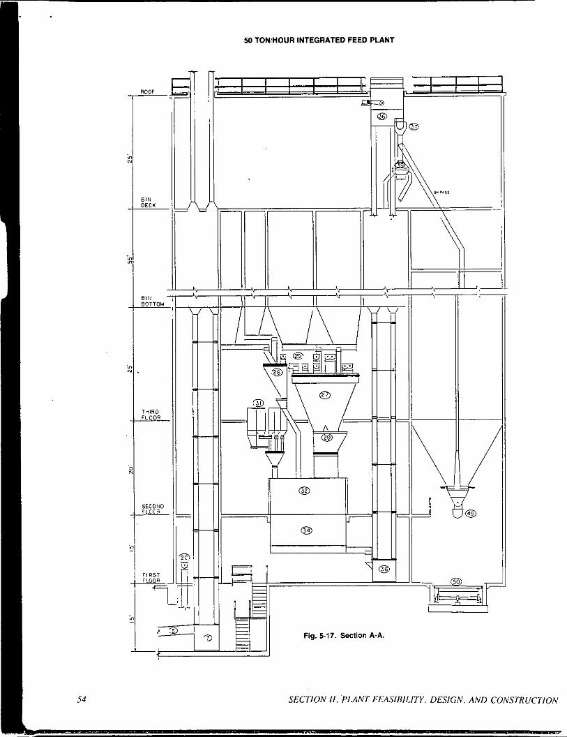
50 TON/HOUR INTEGRATED FEED PLANT
54 SECTION I I . PLANT FEASIBILITY. DESIGN. AND CONSTRUCTION
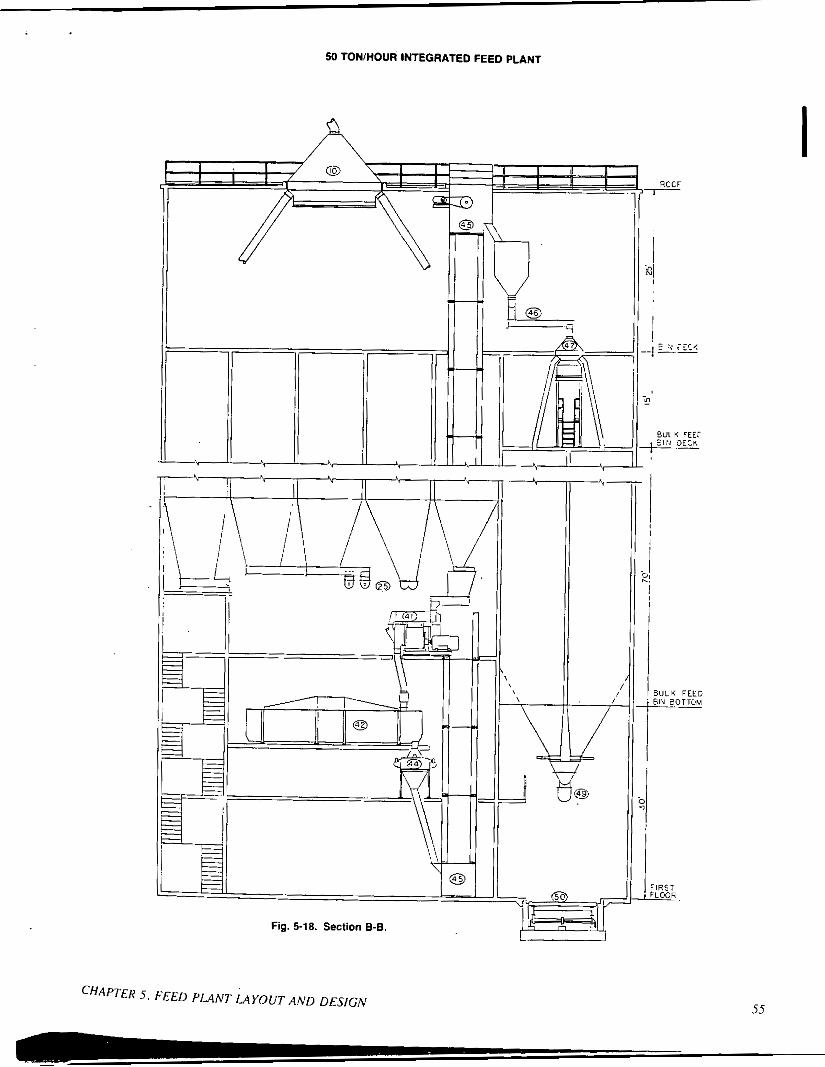
50 TON/HOUR INTEGRATED FEED PLANT
CHAPTER 5 . FEED PLANT LAYOUT AND DESIGN

50 TONlHOUR INTEGRATED FEED PLANT
Fig. 5-19. Section C-C.
Srorup arid Ingredienr Biii Dr.sigir. Approximate amounts of each ingredient to he stored can only he determined from a knowledge ofthe rateofusage ofeach ingredient. size of loads. and knowledge o f elapsed time between when an ingredient is ordered and when it is received.
The ingredient usage table shows the development of Usage data to arrive at the number and size of ingredient bins. First. the ingredients usage was determined from the basic design criteria. The bin usage table was then prepared to show total ingredient storage to be provided. An adjustment was made in some of those values after the bin sizes were finally agreed upon. The actual cubic feet of storage assigned was converted to tons of storage. based on the density of the ingredient as shown. Then. the average days 01 storage was determined. By dividing the usage in tons per d3). b! load sire. the average loads per day of each ingredient and total loads per day can be determined.
Grinding. Grinding requirements may he up to 70% of the total production rate. o r 35 tons per hour on an */"/N-inch or '%-inch screen. Since this plant is expected to produce 90% of its feed as broiler pellets o r crumbles. most grinding will he fine. Some limited coarse grind may he required to produce nonpelleted breed- e r feeds. A single hammermill is generally not large enough to handle this requirement. Accordingly. two hammermills were selected. Less time is required for starting and stopping the mills. since they grind for longer periods with fewer screen changes required. There is some safety factor if one mill breaks down.
Hammermills were selected because a finergrind i h required for the pelleted feed. Roller mills are not used as frequently for finely ground materials. Attrition mills were no! considered.
Burch Wcighir~g. Ingredients have been classified as major. minor. or micro according to the relative quantity generally re- quired for a feed. Small quantities are difficult to accurately weigh on a large scale. Forthis reason. three scales h m e been prwided: an 8000-lh scale fnr major ingredients. a 2000-lb scalc for minoi ingredients. and a 100-lb scale for microingredients. The major scale will handle the principal ingredients of corn. soybean meal. protein meals. and by-products. The 2000-lb scale can handle the minerals plus. possibly. some specialty protein products.
Mi~,.,iiirgrrdieirr.s. This design example includes an auto- matic hulk microingredient system. It does add to the initial cost o1 the plant: however. i t provides better quality control. reduces labor. eliminates plant time for nvaking premixes. and improves record keeping. Many poultry feed plant owners have found that i t > advantages make i t a desirable and feasible option.
Mi.yifrg. One 4-1011 mixer with surge bin u'as selected u,ith provisions for a future +ton mixer. Mixing time is ehpected IC
require minute to charge the mixer from scale hoppers. 3 minutes mix time. and a maximum of '/? minute to discharge the mixer i n t o the surge hin. A 4-minute niix cycle provides for a gross output of 15 batches per hour. or 60 tons per hour. The ne1 production is expected to be 50 tons per hour on a continuous basis.
Provision is made for adding liquids. including IOU. lewis 01 fat (up 10 1 % ) in the mixer. Priwision is also made for adding tu'v other liquids - choline chloridc and methionine, Sonis poultr) plants utilize even more liquids. From the niihers. the feed i s elevated t o a distrihutor ser\,ing the pellet mash bins w e r the pellei mills. I t also spouls to the bulk 1o;id-out hins.
Pd/dif,y. Ninety percent prnc!uctinn of pellets and crumble! requires two pellet mills. Two mash hins se rw each o f the nlills. The pellets drop intoacuoler directly under the mills. Crumble roll? are installed at the cooler discharge. Pellets and crumbles arc elevated to the top of the mill as a finished feed. Most poultry mill: serving integrated operations do not screen pellets and crumhles.
At the end of a run and after the cooler has been sujitched IC
56 SECTION 11. PLANT FEASIRILITY., DESIGN. AND CONSTRLICTIOh'
50 TONlHOUR INTEGRATED FEED PLANT
. --_
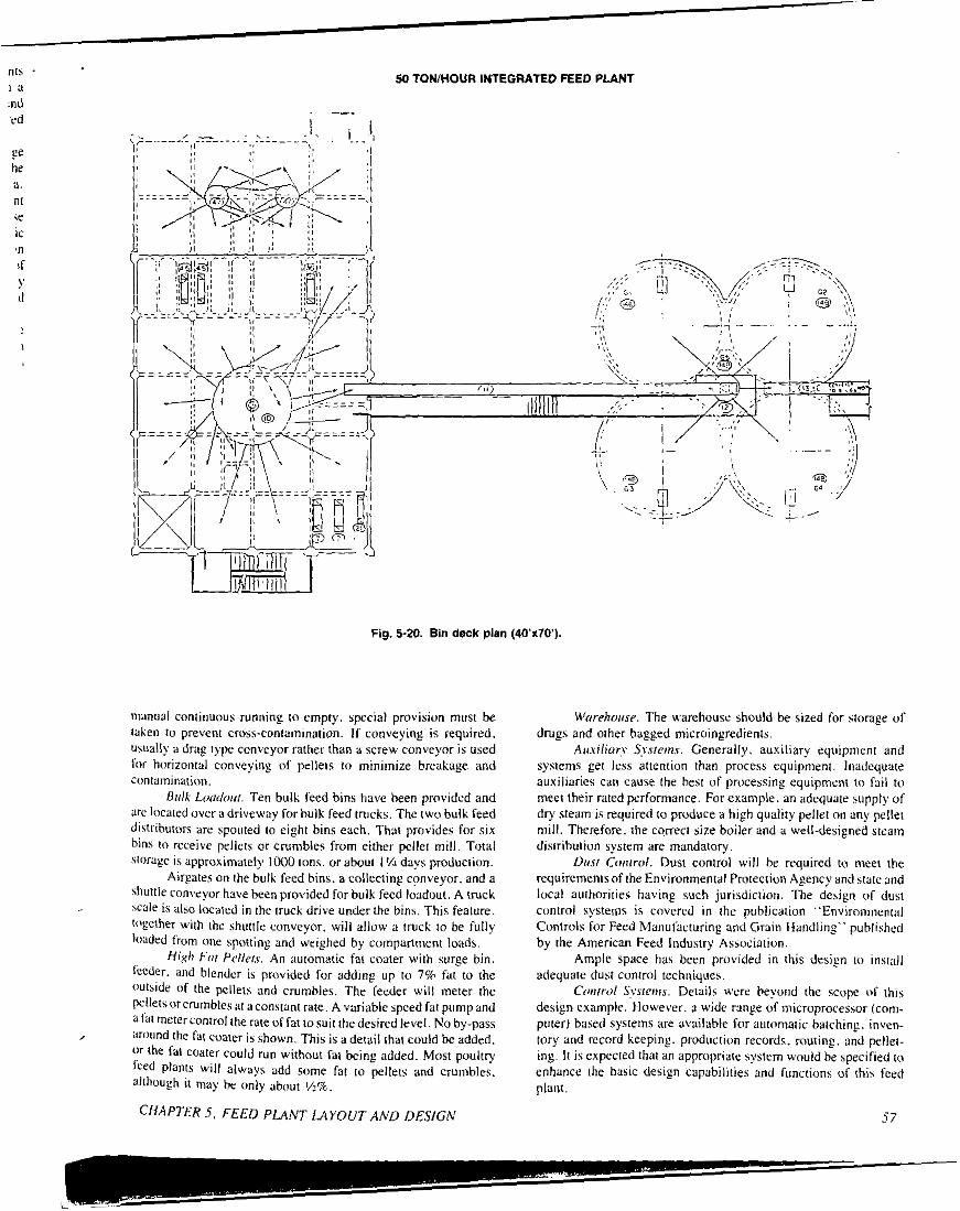
Fig. 5-20. Bin deck pian (40x70) .
nianual continuous running to empty. hpecial pro\,ision must be taken to prevent cross-contamination. If conveying is required. uhually a drag type conveyor rather than a screw conveyor is used lor horizontal conwying of pellets to minimize breakage and cantamination.
B s l k Loodoui. Ten bulk feed bins have been provided and are located over a driveway for bulk feed trucks. The two bulk feed dirtributors are spouted io eight bins each. That provides for six bins lo receiYe pellets or crumbles from either pellet mill. Total storage is approximately IOM) ions. or about I 'A days production.
Airpates on the bulk feed bins. a collecting conveyor. and a shuttle conveyor have been provided for bulk feed loadoul. A truck scale is also located in the (ruck drive under the bins. This feature. @ether ujith the shuttle conveyor. will allow a truck to be fully IlJaded from one sporting and weighed by cornpartmen1 loads.
H i g h For Pellprs. An automatic fat coater wilh surge bin, (i.cder. and blender is provided for adding up to 7% fat to the wl.\ide of the pellets and crumbles. The feeder will meter the Pelletsorcrumbles at aconsiant rate. A variable speed fa1 pump and a~~~met~rcontrolrherateoffattosuitthedesiredlevel. No by-pass
'lr the fat coater could run without Fat being added. Most poultry seed Plants wi l l always add some far to pellets and crumbles. allhough i t may hc only ablrut y2%.
, around the fat c o m r is shousn. This is a detail that could be added.
5 . FEED PLANT LAYOUT AND DESIGN
Worehoase. The u,arehouse should be sized for storage of drugs and orher bagged microingredients.
Awilior? S?.sieins. Generally. auxiliary equipment and systems get less attention than process equipment. Inadequate auxiliaries can cause the best of processing equipment to Pail to meet their rated performance. For example. an adequate supply of dry steam is required to produce a hi&h quality pellet on any pellet mill. Therefore. the correci size boiler and a well-designed steam distribution system are mandatory.
Dusr Coi~irol. Dust control will be required to nieet the requirements of the Environmenial Protection Agency and stale and local authorities having such jurisdiction. The derign of dust control systenis is covered in !he publication "Environmental Controls for Feed Manufacturing and Grain Handling" published by the American Feed Industry Association.
Ample space has been provided in this design to install adequale dust control techniques.
Coirrwl S w r e ~ n ~ . Details were beyond the scope of this design example. Houwer. s wide range of microprocessor (corn- puler) based systems are ao i lab le fur automatic batching. inven- tory and record keeping. produclion records. routing. and pellet- ing. I t is expected that an appropriate system would be specified ((1
enhance the baric design capabilities and functions of this feed plant.
57

Table 5 2 . INGREDIENT USAGE AND STORAGE OF 50 TON/HOUR INTEGRATED POULTRY PLANT.
Max. Min. Load Storage
Lbs. Per Usage Size Desired Storage Provlded Ingredient Cu. Ft. % TPD (Tons) (Days) Tons Days
Corn 45 62 496 500'" 10 5380 11
-. Gluten Mf
Soybean Meal 42 17 136 90 4 550 4 Poultry By-product Meal 35 4.5 36 22 6 270 8 BakeN By-product 40 3.5 28 20
Fish Meal 44 3 24 22 5 120 5 Meat & Bone Meal 45 1.5 12 22 4 50 4
Phosphate 70 1 8 90
Salt 80 0.1 0.8 22 5 35 44"'
Liquids - 3.1 24.8 20 Micros - 0.4 3.2 -
6 240 9'1'
!ai 36 3 24 90 5 480 20'"
Blood Meal 45 0.5 4 20 6 50 13'''
Limestone 85 0.4 3.2 22 5 40 17'"
5 280"' 36VY"
Total 100.0 800.0
Storage Provided was controlled by load size. resulting in more days Storage than minimum desired ''I Two twes of DhosDhate to be handled ./l/ Excess storage. b i t controlled by bin space allocation and VI 5 Car Multi.
bin splits
Table 5-3. INGREDIENT BIN ALLOCATION 50 TON HOUR INTEGRATED POULTRY PLANT.
Ingredient (Tons) (Tons) (Tons) Corn 5200 180 5380 Soybean Meal Poultry By-Product Meal
Bakery By-Product Gluten Meal Fish Meal Meat and
Bone Meal Blood Meal Phosphate Limestone Salt UtilitV
450
0 0
400 0
0 0 0 0 0
125
100
270 240 80
120
50 50
280 40 35
240
550
270 240 480 120
50 50
280 40 35
365 Total"' 6175 1685 7860
( I ) Excludes Liquids and Micros
58 SECTION II. PLANT FEASIBILITY. DESIGN. AND CONSTRUCiI(

I L iired '
ieter wdy
plc- 140 The
ees
he of
en
ac-
i
i i
o i
re I v. I
I
t i i i 1
!
i
C h a p t e r 13
Dust Collection Systems
Gary L. McDanlel MAC Equipment, Inc.
A dust collection system serves many purposes. Good housekeeping in conjunction with proper dust control will reduce insect and rodent problems and other hazardous contaminants. The benefits of clean working conditions will outweigh the costs in the long run because the employer will maintain a more experienced. efficient staff and will be able to meet the requirements of OSHA much easier.
Good housekeeping could also result in a lower insurance rate. The insurance rate is determined by the general housekeeping and appearance of a facility, and some companies will give a lower rateforthe installationofanadequatedust controlsystem. I fap lan t has an adequate dust control system. housekeeping will be ac- complished with less effon and fewer man hours spent. Some insurance companies will not insure facilities that d o not have pneumatic dust control systems that meet their standards.
Dust control can reduce loss or shrinkage of the product heins handled by controlling dust emission points either by con- tainnient or aspiration. Captured dust can he returned to the stock handling system or collected in a dust bin and utilized later. Reduced shrinkage can add to the profit of a company.
Many studies have been conducted and information has been gathered on dust explosions in elevators and feed plants.
What causes a dust explosion? A grain dust explosion can occur only if four factors co-exist: oxygen, an ignition source. il confined Yolume. and suspended dust. Eliminating any one of the fmors ulill eliminate the possibility of explosion. however. this i s easier said than done. Since the first three factors are somewhat uncuntrdlahle. researchers and manufacturers look toward dust control to lower the chances of dust explosions. For a general definitionoftermsapplied todust collection systems. see Appendix A.
DUST PRODUCING POINTS Dust producing points in a typical feed plant include the
recei\,ing areas. hammermills. roller niills and crimpers. mixing W e m . elevatur legs and distributors. screw and drag conveyors. belt conveyors. pellet scalpers. bag&ers. and loadout areas.
TOTALENCLOSURE
Receiving Area Truck and rail receiving areas are a source of dust emissions
in the feed plant. Since many receiving areas are not fully enclosed. fugitive and nuisance dust results. Controlling dust in receiving areas is difficult because of the variety of trucks and rail vehicles. Trucks consist of semitrailers with fixed bodies. semitrailers with self-dumping bodies. short trucks with both fixed and self-dumping bodies. and hopper bottom trailers. Railcars consist of hopper bottom cars and box cars. It is difficult to design a receiving area to accommodate all units.
Most feed plants have some type of receiving pit or dump pit. I t may be enclosed. parfially enclosed. or totally enclosed. lfit i s an unenclosed area. the effect of wind, a major contributing factor to dust problems in receiving areas, must he taken into account. Wind can be of a magnitude that is impractical to combat with a dust suction system. Capture velocities in the range of 150 to 250 ftlmin function adequately under static condilions. However. as can be noted from the following chan. a IO-mile per hour wind i s equiv- alent to a velocity of 880 ftlmin.
Wind (milh) Velocity 5 440 IO 880 20 I760 30 2640
I t is not practical to capture dust with a dust suction system in a rrceiving area if the wind is of any magnitude at all. Wind should not be fought with air. I t is advised that all receiving areas have some type of enclosure. The feed plant operator must give con- sideration to some type ofenclosure for dust suction to be effective (Figure 13-11, A partial enclosure can he effective in areas of limited or small wind velocities. A total enclosure is the best choice. Total enclosure will ensure the feed plant operator of an adequate. efficient dust cuntrol system under all conditions. ,
There are two methods of controlling dust at a receiving pit. Dust pickup below the grate is effective on large deep pits. whereas dust pickup above the prate is recommended for shallow pits. Suction below the grate works well on large pits in which the
i
5SIOED ENCLOSURE
Fig. 13-1. Receiving enclosure.
CHAPTER 13. DUST COLLECTION SYSTEMS 113

Fig. 13-2. Below grate dump pit dust pickup.
ingredients do not build up above grate level when dumping (Figure 13-21, Suction should be installed into the pit area where i t w i l l not draw ingredients into the dust system. This possibility can be reduced by installing a stationary baffle to provide an area i n the dump pit into which the ingredients cannot flow. When sizing a system for below the grate pickup. 150 cfm per square foot o f open grate area i s recommended. For example. if the grate i s 10 ft by 10 ft. the flow rate recommended is:
100 sq ft x 150 cfm/sq ft = 15,000 cfm
The flow rate can be reduced by installing baffles below the grate. reducing the effective open area. The open area can be reduced 50 to 60% with baffles and s t i l l maintain adequate openings for ingredient flow. I f , i n the example above. baffles are installed to reduce the open area by 50%. the air volume can be reduced to 7.500 cfm.
For shallow pits (Figure 13.3). the pickup points should be located at floor level on both sides o f the driveway or. in the case of a back-up dump pit. can be located at the back o f the grate. The
o " a , s T = r n ~
DUMPPI,
'm W'
CO*YE"OR
Fig. 13-3. Above grate dump pit dust pickup
I I4
pickup hoods should be located as close to the grate as possib without obstructing the trucks or railcars. I t is recommended th the system be designed for 10,000 to 15.000 cfm air volume. Th must be a judgment decision on the part o f the designer. givi i consideration to the type of enclosure. how close the pickup pain are to the grate, how large the grate is, and what type of vehicle dumping. A hopper dump vehicle does not generate as much dust : a tail dump.
Hopper dump units generate the least amount o f dust i f t l gate i s fully opened and the dump pit i s choke fed. Do not run partially open gate. If the unit i s choke fed, the only dust emissioi are when the gate is initially opened (Figure 13-4). An above-th, grate pickup i s effective in controlling dust for hopper dump trucl or railcars
"OPEN
+====
Fig. 13.4. Hopper dump.
I t i s recommended that aspiration be applied on a floor dum above the grate (Figure 13-5). For practical purposes, a belouwh! grate pickup would inhale material into the pickup point. To t effective with a minimum amount of air. i t i s necessary to cnclo: as much of the grate as possible. Three sides should be enclosed possible. For an above-the-grate pickup. use I25 to 200 cfm o f a per square foot of grate area. For example. a grate 2 ft by 2 ft woul equal 4 square feet of area. Therefore:
4 sq R x 150 cfmlsq R = 600 cfm
To use the air most effectively. a pickup should be as close to th grate as possible at the back side of the hood: however, anothe method that has been used frequently i s to install the pickup point; the top of the hood (Figure 13-61, Positioning the pickup at the to
Fig. 13-5. Floor dump.
SECTION 111. BULK MATERIALS HANDLING AND STORAGE
ILE"1.0" "E.0
I
Fig. 13-6. Standard hood for flOOr dump opening.
ofthe hood, however, tendstousemorecfmpersquarefootofgrate asopposed to positioning it at the back side of the hood. as close to the grate as possible.
Conveying Equipment Elevator legs and distributors deserve considerable attention
because i t is at this p i n t where much controversy arises. The controversy is created by the fact that the elevator leg has been the origination of almost all dust explosions in the past years. There are two points to deal with on an elevator leg - the boot and the head. There are two reasons why internal pressure is created within an elrviltor boot. When the elevator boot is being filled with in- predients. air is displaced. Also. the movement of the cups in the down side uf the leg are acting as an air pump causing air movement into the boot section.
At the elevator head. the emptying of the buckets tends to cause a reduction of air pressure within the head section. Under normal conditions. pressures within the elevator head tend to be slightly beluu, atmospheric: however. other factors may affect the head section. If the head discharges through a spout to a tight bin o r dislributur. the air displaced in the distributor will have to come hack up the spout in the direction opposite to that of the ingredient movement. Thecountertlow ofairwill carryaconsiderable volume of dust back into the elevator heads resulting in puffs of dust laden air being blown out of the vpenings of the head section. That problem can be eliminated by applying aspiration on the up leg above the boot section and by proper venting (if bins and distributor.
Past practice has been to place the prime air pickup point on top ofthe boot and side of the head. This provides enough suction to keep the leg under negat ix pressure. One of the problems with that t?pe of thinking u'as that the leg was probably still well above the minilnUm explosive limit. In addition, the designer was also tight- inE the natural movement of air created by the belt and buckets plus the Pressure from the entrained air entering through the feed inlet and. thus. was probably creating a greater dust concentration in the leg where the buckets are being filled and exiting the hoot section.
MAC Equipment has conducted research on elevators and has concluded that the most efficient use of aspirativn is on the up side of the leg above the boot hection as opposed to the tup of the bout. Those studies also concluded that. with increased aspiration.
CHAPTER 13. DUST COLLECTION SYSTEMS
CL-
Fig. 157. Elevator leg.
the dust concentration is lowered. When applying this method to a feed ingredient leg. care must he taken not to draw too high a percentage of ingredients from the leg (Figure 13-71.
In fact, tests on legs handling whole grain prove that dust concentrations can be reduced below the minimum explosive limit by using this simple formula to determine cfm:
Area of leg Wmin of 1.25 = minimum in sq ft belt travel explosive limit
For example:
4 sq R x 500 Wmin x 1.25 = 2500 cfm
MAC'S recommendation is to apply one-third of the total cfm to the head section if the leg is over 90 ft tall and two-thirds to the boot area. specifically. to the up side of the leg above the boot section.
Generally speaking. screw and drag conveyors do not pro- duce great amounts of dust: however. even a minimal amount of dust should be given consideration. Must of the dust is produced at the inlet p i n t where the ingredients are fed onto the conveyor. Air and dust enters the housing of the conveyor: therefore. the housing must he vented to relieve the internal pressure. MAC also re- commends using the volume of the incoming ingredients times 20 to determine cfm. since the air entrained with the flowing in- gredients is considerably more than most people believe it to be. For example. a conveyor handling 15 tons per hour calculates to:
12.5 cfm x 20 = 250 cfm
Belt conveyors produce dust at the loading point where the product is spouted onto the belt (Figure 13-8). A common hood can be provided for receiving the product and fbr a dust suction connection. The design of the hood is somewhat dependent on belt speed. Assuming a belt speed of 500 to 600 ftlmin. a total length of 4 It is recommended. The discharge end of the hood should prwide approximately 3 in. clearance a b w e the belt fur the product to pass. The sides of the hood should he fitted u,ith flexible flashing to hold the minimum clearance tu the belt. Use 250 to 350 cfm per foot of belt width. The cfm is dependent on the belt speed. The faster the belt runs. the more cfm that is required to capture the dust.
I15
A
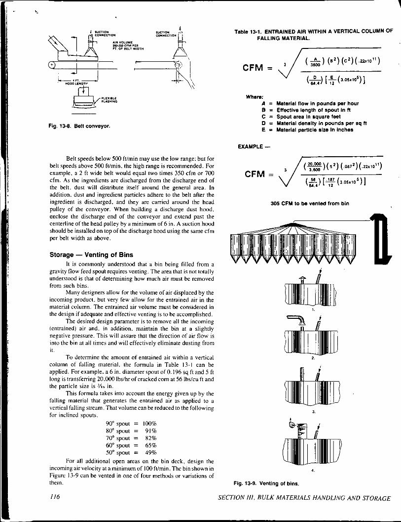
Fig. 13-8. Belt conveyor.
Belt speeds below 500 ftlmin may use the low range: but for belt speeds above 500 fUmin. the high range is recommended. For example. a 2 ft wide belt would equal two times 350 cfm o r 700 cfm. As the ingredients are discharged from the discharge end of the belt. dust will distribute itself around the general area. In addition. dust and ingredient panicles adhere to the belt after the ingredient is discharged. and they are carried around the head pulley of the conveyor. When building a discharge dust hood, enclose the discharge end of the conveyor and extend past the centerline of the head pulley by a minimum of 6 in. A suction hood should be installed on top of the discharge hood using the same cfm per belt width as above.
Storage - Venting of Bins I t is commonly understood that a bin being filled from a
gravity flow feed spoul requires venting. The area that is not totally understood is that of determining how much air must be removed from such bins.
Many designers allow for the volume of air displaced by the incoming product. but very few allow for the entrained air in the material column. The entrained air volume must be considered in the design if adequate and effective venting is to be accomplished.
The desired design parameter is to remove all the incoming (entrained) air and. in addition, maintain the bin at a slightly negative pressure. This will assure that the direction of air flow is into the bin at all times and will effectively eliminate dusting from i t .
To determine the amount of entrained air within a vertical column of falling material. the formula in Table 13-1 can be applied. For example. a 6 in. diameter spout of 0.196 sq ft and 5 ft long is transferring 20.000 Ibslhrof cracked corn at 56 Ibslcu ft and the panicle size is Y I ~ in.
This formula takes into account the energy given up by the falling material that generates the entrained air as applied to a vertical falling stream. That volume can be reduced to the following for inclined spouts.
90" spout = 100% 80" spout = 91% 70" spout = 82% 60" spout = 65% 50" spout = 49%
For all additional open areas on the bin deck. design the incoming air velocity at a minimum of I00 ftlmin. The bin shown in Figure 13-9 can be vented in one of four methods or variations of them.
116
Table 13-1. ENTRAINED AIR WITHIN A VERTICAL COLUMN OF FALLING MATERIAL.
V (L) 64.1 [ ~ ( 3 . 0 5 x 1 0 5 ) ] 12
Where: A = Malerlal (low In pounds per hour B = Effective length of spout In f l C = Spout area In square feel D = Material density In pounds per sq n E = Malerlal parllcle size In lnchea
EXAMPLE -
305 CFM to be vented from bin
wvvvvvvwvvvv I
1.
2
Fig. 13-9. Venting 01 bins.
SECTION 111. BULK MATERIALS HANDLING A N D STORAGE
~~~~~~ ~

I . F
2.
3.
4.
An open vent stub with only a weatherhood for protection. There is little that needs to be said for this system. I t relieves the positive pressure and relieves all the fines t o the at- mosphere. This is not an acceptable method for most users from a standpoint of their own housecleaning. from neigh- bors. or from OSHA acceptance. A vent line from the enclosed bin to an existing dust col- lection system. This appears to be a simple solution, but it usually fails to be acceptable in the long term. The major disadvantage is. if the vent line is applied as illustrated, i t will remove all vented air from the bin but maintain a high volume ofair through the duct at all times. whether the bin is being filled or not. A manually cleaned vent sock. This system often does not eliminate dusting. The spout entry to the bin and the bin deck must he sealed, as the bin is always under positive pressure. The cleaner the bag, the better the venting action. The longer the bag goes unattended. the greater the positive pressure within the bin and the more likely that dusting will occur. Manually cleaned vent socks should be sized at 4: I air-to- cloth. A compressed air filter with a suction fan. Its ability to self clean and maintain the bin under a slightly negative pressure provides the desired design condition and makes i t the most effective method. Sizing the filter is typically at 1 0 1 air-to- cloth ratio for feed grains without additives that are adhesivc or cohesive. With those additives present. the air-to-cloth ratio should be decreased to 8:I . The suction fan should he sized at the design cfm and a negative S i n . water gauge (wgl. This is a closed system that returns all dust to the bin i t came from with no material loss.
Cleaning Equipment By the time feed gets to the pellet scalper. there is usually
v e q little dust left (Figure 13-10). However. the pellet scalper shakes the ingredients. separating the fines from the pellets. Any dust that is present mushrooms out into the surrounding area. It is recommended that a lightweight hood be built over the pellet scalper. I t should be light enough in weight so that it does not affect
Fig. 13-10. Pellet scalper.
CHAPTER 13. DUST COLLECTION SYSTEMS
the shaking action of the unit, and a flexible hose is required 10 compensate for the movement. Cfm can be determined by the open area available through the scalper mechanism. This is usually the product inlet area and the product discharge. Use of 250 cfm per square foot of open area is recommended. For example. if the scalper has a 12 in. square inlet and a I2 in. square outlet, that gives a total of 2 square feet. Therefore.
250 cfm/sq ft x 2 sq ft = 500 cfm
Processing Equipment The processing equipment used in a feed plant includes full
circle andlor conventional hammermills. a mixing system, roller mills, crimpers, pellet mills, and coolers. CAUTION: Probably the most hazardous piece of equipment in the feed plant is the hammer- mill because of its high speed. I t has the potential of producing sparks from foreign objects. Those sparks carry through the stock handling system and Stan fires or are potential dust explosion hazards. When designing a new feed plant. consideration should he given to locating the hammermill outside.
Fig. 13-11, Full circle hammermill.
Full circle hammermills should be vented (Figure 13-11). First. the rotor of a mill turning at high speeds produces a cen- trifugal fan action. pressurizing the hammermill housing. Venting will help alleviate dust belching out of the housing inlet. outlet. or any opening. Secondly. when grinding grain. there is a moisture release and temperature increase due to friction. I f the air is not vented. moisture will condense in the lower portion of the mill housing and the conveyor lo cause rusting and corrosion. In addition. it is possible for the temperature to build up around 150°F in the housing. The combination of temperature with condensed moisture causes the product to become very sticky and handling problems result. It is recommended that 71% io l0cfm per hammer- mill hp be used for ventins a full circle mill. For example, a 100 hp mill wouldtake I(K)times IOcfmor 1000cfm. Becauseofthehigh nioisture released and assuming a filter is being used, a 70" hopper on the filter is recommended lo eliminate bridging and plugging.
Emissions from the air lift of a conventional hammermill
117
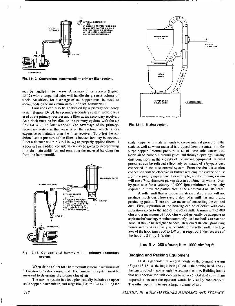
*IYUE*YIL,
Fig. 13-12. Conventional hammerrniil - primary finer system.
may be handled in two ways. A primary filter receiver (Figure 13-12) with a tangential inlet will handle the greatest volume of stock. An airlock for discharge of the hopper must he sized to accommodate the maximum output of each hammermill.
Emissions can also be controlled by a primary-secondary system(Figure 13-13). Inaprimary-secondarysystem. acycloneis used as the primary receiver and a filter as the secondary receiver. An airlock must be installed on the primary cyclone with the air flow taken to the filter receiver. The advantage of the primary- secondary system is that wear is on the cyclone. which is less expensive to maintain than the filter receiver. To offset the ad- ditional static pressure of the filter. a booster fan may be needed. Filter resistance will run 3 to 5 in. wg on properly applied filters. If a booster fan is added, consideration may be given to incorporating i t as the main airlift fan and removing the material handling fan from the hammermill.
1,1711
Fig. 13-13. Conventional hammermill - primary secondary system.
When sizing a filter for a hammermill system. a maximum of 9: I air-to-cloth ratio is suggested. The hammermill system must be surveyed to determine the proper cfm of air.
The mixing system in a feed plant usually includes an upper scale hopper. batch mixer. and surge bin (Figure 13-14), Filling the
Fig. 13-14. Mixing system.
scale hopper with material tends to create internal pressure in the scale as well as when material is dropped from the mixer into the surge hopper. Internal pressure in all of these units causes dust laden air to blow out around gates and through openings causing dust conditions in the vicinity of the mixing equipment. Internal pressures can be relieved effectively by nieans of a by-pass duct connected to the dust control system. From the duct. a suction connection will be effective in funher reducing the escape of dust from the mixing equipment. For example. a ?-ton mixing system will use a 7-in. diameter pickup duct in combination with a IO-in. by-pass duct for a velocity of 4000 fpm (minimum air velocity required to move the particulates in the air stream) or 1060 cfm.
A roller mill that is producing steam flaked grain will not produce much dust: however, a dry roller mill has many dust producing points. There are two means of controlling the emitted dust. First, aspiration of the housing can he effective with con- sideration given to the size of the roller mill. A minimum of 400 cfm and a maximum of 1000 cfm would generally he adequate to aspirate the housing. Another commonly used method is an exterior hood. It should be designed to adequately cover the dust producing points and to fit as closely as possible to the roller mill. The face area of the hood times 200 to 250 cfm is required. I f the face area of the hood is 2 ft by 2 f t . then:
4 sq fl x 250 cfm/sq fl = 1000 cfm/sq f l
Bagging and Packing Equipment Dust is generated at several points in the bagging system
(Figure 13-15~:asthebagisbringfilled.atthesewinghead.andas the hag is pulled to gii through the sewing machine. Building hoods that will enclose the unit enough to achieve total dust control are impossible because the operator would be \,isually handicapped. The other option is to use a large volume of air.
SECTION Ill. BULK MATERIALS HANDLING AND STORAGE 118
I I
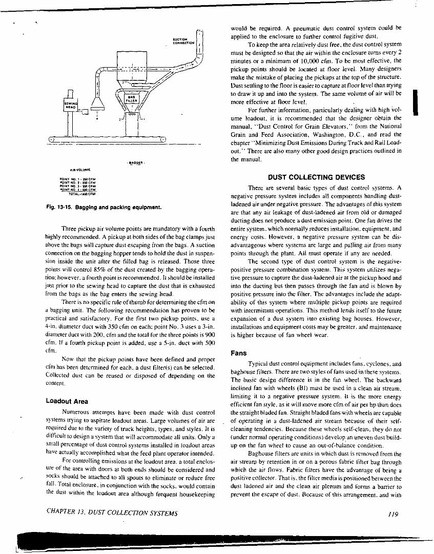
Fig. 13-15. Bagging and packing equipment.
Three pickup air volume points are mandatory with a fourth highly recommended. A pickup at both sides of the bag clamps just above the hags will capture dust escaping from the hags. A suction connection on the bagging hopper tends to hold the dust in suspen- sion inside the unit after the filled bag is released. Those three points v,ill control 8.5% of the dust created by the bagging opera- tion: however. a fourth point is recommended. I t should be installed just prior to the sewing head to capture the dust that is exhausted from the hags as the hag enters the sewing head.
There is no specific rule of thumb for determining the cfm on a bagging unit. The following recommendation has proven to he practical and satisfactory. Far the first two pickup points. use a 4-in. diameter duct with 350 cfm on each: point No. 3 uses a 3-in. diameter duct with 200. cfm and the total for the three points is 900 cfm. I f a fourth pickup point is added. use a 5-in. duct with 500 cfm.
Now that the pickup points have been defined and proper cfm has been determined for each. a dust filter(s) can he selected. Collected dust can he reused or disposed of depending on the content.
Loadout Area Numerous attempts have been made with dust control
systems trying to aspirate loadout areas. Large volumes of air are required due to the variety of truck heights. types. and styles. I t is difficult to design a system that will accommodate all units. Only u small percentage of dust contro1 systems installed in loadout areas have actually accomplished what the feed plant operator intended.
For controlling emissions at the loadout area. a total enclos- ure of the area with doors at both ends should be considered and socks should be attached to all spouts to eliminate or reduce free fall. Total enclosure. in conjunction with the socks. would contain the dust within the loadout area although frequent housekeeping
CHAPTER 13. DUST COLLECTION SYSTEMS
would be required. A pneumatic dust control system could be applied to the enclosure to further control fugitive dust.
To keep the area relatively dust free, the dust control system must be designed so that the air within the enclosure turns every 2 minutes or a minimum of 1O.ooO cfm. To be most effective. the pickup points should be located at floor level. Many designers make the mistake of placing the pickups at the top of the structure. Dust settling to the floor is easier to capture at floor level than trying to draw it up and into the system. The same volume of air will be more effective at floor level.
For further information. particularly dealing with high bo!- ume loadout, it is recommended that the designer obtain the manual, "Dust Control for Grain Elevators." from the National Grain and Feed Association, Washington. D.C.. and read the chapter "Minimizing Dust Emissions During Truck and Rail Load- out." There are also many other good design practices outlined in the manual.
I
DUST COLLECTING DEVICES There are several basic types of dust control systems. A
negative pressure system includes all components handling dust- ladened air under negative pressure. The advantages of this system are that any air leakage of dust-ladened air from old o r damaged ductingdoes not produce adust emission po in t . One fan drives the entire system. which normally reduces installation. equipment. and energy costs. However. a negative pressure system can be dis- advantageous where systems are large and pulling air from many points through the plant. All must operate if any are needed.
The second type of dust control system is the negative- positive pressure combination system. This system utilizes nega- tive pressure to capture the dust-ladened air at the pickup hood and into the ducting but then passes through the fan and is blown by positive pressure into the filter. The advantages include the adapt- ability of this system where multiple pickup points are required with intermittant operations. This method lends itself to the future expansion of a dust system into existing hag houses. However, installations and equipment costs may he greater. and maintenance is higher because of fan wheel wear.
Fans Typical dust control equipment includes fans. cyclones, and
baghouse filters. There are two styles of fans used in these systems. The basic design difference is i n the fan wheel. The backward inclined fan with wheels (BI) must be used in a clean air stream. limiting i t to u negative pressure system. I t is the more energy efficient fan style. as i t will move more cfm of air per h p than does the straight bladed fan. Straight bladed fans with wheels are capable of operating in a dust-ladened air stream because of their self. cleaning tendencies. Because these wheels self-clean. they do nnt (under normal operating conditions1 develop, an uneven dust build. up on the fan wheel to cause an out-of-halance condition.
Baghouse filters are units in which dust is removed from the air strearv by retention in or on a porous fabric filter bag through which the air flows. Fabric filters have the advantage of being a positive collector. That is. the filter media is positioned between the dust ladened air and the clean air plenum and forms a harrier to prevent the escape of dust. Because of this arrangement. and with
119

the proper filter media selection. efficiencies of 99.8% can be achieved
There are three basic types of filters used in the feed industry.
Low pressure, high volume reverse air cleaning filters are commonly used. Because they clean with low pressure air. internally mounted fans provide all cleaning air needed. There are no compressors, no air lines to freeze in cold weather, and no valves or mechanical flaps to fail. These units are ideal for cleaning where high humidity and freezing conditions are common. They also lend themselves to out- side locations.
0 High pressure compressed air. commonly called Reverse Pulse. filters are also used. The cleaning action of the hags is accomplished by the use of compressed air. The filters have a compressed air header that stores high pressure air until the control panel timer electrically fires (or discharges) one row of bags at a time and cleans each row in the unit on an adjustable time basis.
0 Shakerfilrers are designed for low maintenance and are used when no compressed air is available. A rocking arm shaker mechanism accomplishes hag cleaning and can he either
Table 13-2. EFFICIENCY CHART FROM FIELD TEST H. E. COLLECTORS.
manually operated or motor driven. Snap band bag removal from the tube sheet is quick and easy while assuring a positive bag seal. There are two major disadvantages of the shaker filter. First. i t is not a continuous filtering unit, since the air flow must be shut off during the cleaning operation; and second, the air-to-cloth ratio must be held to a maximum Of4.1.
Cyclone Collectors There are many styles of cyclone collectors. Many are very
good collectors. but all are limited to features that affect their efficiency and capability: collector body diameter. air inlet velo- city. dust loading. panicle size. and panicle density. The proper application for a centrifugal collector is one which can be precisely defined and controlled so that performance can be maintained. Examples of this type of system would be pellet coolers. petfood dryers, andother high temperature, high moisture. low dust loading applications. Field test results that indicate high efficiency (no visible emission) from this type system can he obtained from most knowledgeable manufxturers (Table 13-2).
MODEL TYPE PRODUCT
PSil*ed
FWd * * ' 2H36 Cettle
' 2H39 Extruded Pettwd 7TPH
OPTIMUM ACTUAL OUTLET EMISSION- MASS EMISSIONS FIELD AIR FLOW AIR FLOW TEMPERATURE GRAINS PER EFFICIENCY SOURCE TEST
1000 CU. FT. LOCATION
Land.0-Lakes 14250 14111 Calllornia CFM CFM 66' ,052 99.97% Pellet c1arencs.
15400 15464 152' ,446 99.3% wangsr Tully's
Cooler Iowa
CFM CFM Dryer Perham. Minn.
' 2H43 Extruded 20250 19957 154' CatFood CFM CFM 6 % TPH
,341 93.67% wsngsr Tully's Dryer Perham,
Minn.
2H47 Extruded 23624 13682 204' ,420 83% Proctor- Park Dog Food Schwarlz Foods 7 TPH Dryer K.C. KS.
.; It i s vary important to malnteln therecommended aIr Ilow. This installation was 41% below the DPtimYm air llow causing the much reduced mass elllclency. It I s important to nota that nons 01 Iha above tests had any visible emissions.
MODEL TYPE OPTIMUM ACTUAL OUTLET EMISSION- ALLOWABLE EMISSIONS FIELD PRODUCT AIR FLOW AIR FLOW TEMPERATURE Ibr ihr . EMISSIONS SOURCE TEST
lbs.,hr. LOCATION
* * 2H43 Spent 20250 15160 190' Grain CFM CFM Dryer
3.365 16.030 Rotary Midwest Solvents Atchison. KS.
Midwest Solvents .. 2H43 spent 20250 16200 190' 1.310 16.030 Rotary Grain CFM CFM Atchison. KS. oryar
* + 4H47 spent 47240 37620 190' 3.115 39.760 Rotary ' Midwest Soiventa Grain CFM CFM Atchison. KS. DWW
* Test Conducted by Dr. Jason Annlr. K.S.U. * * Tesl Conducted by Midwest Solvents under observation 01 Kansas Air Envirmma"ta1 Health Division
* ' * Tesl Conducted by M A C Equipment Engineering Department
MAC EOUIPMENT, INC.. Box 205. Sabetha. Kansas66534 TeI. 9133284-2191
I20 SECTION I l l . BULK MATERIALS HAhIDLING AND STORAGE
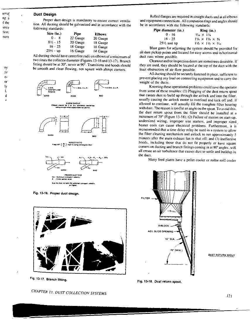
'" :ir
er
1. d
0-
l Y
n
Proper duct design is mandatov to ensure correct ventila- tion. All ducting should be galvanized and in accordance with the
n e a ,f the
ince following standards: Size ( in. ) Pipe Elbows tion:
nun1 0 - 8 22 Gauge 20Gauge 8% - IS 20 Gauge 18 Gauge 16 - 25 I 8 Gauge I6 Gauge
25% - up 16 Gauge 14 Gauge All ducting should have centerline radii onelbows of a minimum of twotimesthecollectordiameter(Figures 13-16and 13-17). Branch filling should be at 30". never at 90". Transitions and hoods should be smooth and clean flowing, not square with abrupt comers.
13-17. Branch fining
CHAPTER 13. D U S T COLLECTION SYSTEMS
Rolled flanges are required in straight ducts and at all elbows and equipmentconnections. All companion rings and angles should be in accordance with the following standards:
0 - 16 Yl" x 11% 16- 25 I % x 1% x %
25% and up 1 % x 11% x ? 4 h
Blast gates for adjusting the system should be provided for all dust pickup points and located for easy access and in horizontal duct runs where possible.
Cleanout andlor inspection doors are sometimes desirable. I f they are used. they should be located at the top of the duci with the least obstruction of air flow possible.
All ducting should be securely fastened in place, sufficient io prevent placing any load on connecting equipment and to carry the weight of the ducts.
Knowing these operational problems could save the operator from some of these troubles: ( I ) Plugging of the dust return spoui that causes dust to build up through the airlock and into the filter. usually causing the airlock motor to overload and kick off and. if allowed to continue. will actually fill the complete filter housing withdust. Thereason istooflatananpleonthespout.Toavoidthis, the dust return spout from the filter should be installed at a minimum of 70" (Figure 13-18); (2) Failure of motors on start-up. undersized wiring. improper size starters, and improper sized, heater coils can cause electrical problems. Furthermore. it is recommended that a time delay relay be used in a system IO allow the filler cleaning mechanism and airlock to run approximaiely 5 minutes after the main exhaust fan is shut ofl: and (3) lnelfective hoods. including those that do not f i t properly or have square comers on ducting and branch fittings coming in ai 90" angles. will all create an air lurbulence that causes dusi to settle and buildup in the duct.
Many feed plants have a pellet cooler or roller mill cooler
Pipe diameter (in.) Ring (in. j
Fig. 13-18. Dust return spout.
DUST RETURN SPOUT
121

system. Products conveyed in these types of systems release mois- ture. In fact. if a collector is being used on the pellet cooler. an average of I 4 to 17% moisture will be released from the exhaust and a baghouse filter would be inefficient. However. when properly applied, a dust collector such as the MAC Hi-Efficiency Collector will eliminate all visible paniculate emissions and meet EPA standards.
When choosing a collector, the most imponant point to remember is that the fan and collector must be in balance with one I another. Therefore, it is wise to purchase the collector and fan from a common manufacturer. The manufacturer will recommend a flow rate desirable for his equipment in combination with the customer's needs. Simply following the manufacturer's recommendations will help to avoid problems.
As previously mentioned. a filter or collector must be in- stalled enabling the discharge tailing spout to be straight or at a minimum of a 70' angle. Also, a s a consequence of moisture release, many collectors operating in cold climates are insulated.
A negative system for pellet coolers is highly desirable because product does not pass through the fan. When a product is passed through a fan. the fan tends to break down the panicle size. This is a disadvantage because the smaller the panicle size, the more difficult i t is to collect the dust.
Panicle size. density. panicle loading. diameter of the collector. and inlet velocity are the crucial factors affecting the performance of any centrifugal dust collector. The higher the inlet velocity. the greater the centrifugal force acting on the dust pani- cles and the greater the separating efficiency.
1 I
I
1 SYSTEM DESIGN
Once a system is designed. i t is imponant tu hire a qualified contractor to insta!l it . There have been many inadequate systems installed due to poor system design and misapplied equipment. Therefore. it is imperative that the dust system he designed and installed properly. The installation of a poorly designed pneumatic dust control system fosters a false sense of security and has often led to inappropriate reduction in scheduled housekeeping.
System design is of utmost imponance. as the effectiveness of the system in concept. control. maintenance. and operation must all be considered, The following steps are to be followed for a systematic concept in design:
Drrerminr rhe dirsr emirring poims. A plant survey and close. observation of existing equipment will expose the dust emit- ting points in the system. Drrer!ninr rhe volume of uir 10 be pulled. To determine the amount of air that is required to he pulled by the system. information must he collected during the plant survey. such aspit sizes. belt widths. legcapacities. mixer sizes, hammer- mill types and sizes, screen types and sizes. bagging equip- ment. etc. Next. determine the amount of air to he pulled from each pickup point. D r w u schonurirdiugrunr of rhe sFsrern. The sketch should indicate a11 pickup points, approximate lengths of runs. and equipment needed. It is simply a worksheet to keep all information tabulated and recorded. Derrrmine die s i x , ond ype of r o l l ~ ~ r r o r . Determine the type of filter or collector and the air-to-cloth ratio to be used.
Culculare rhr srurir loss in the d u d sysrrm. Calculate total system static pressure (sp). To calculate the static loss in the system duct work, the designer must have the duct runs planned for physical routing. This should be done during the plant survey as much as possible. List the lengths of straight runs and the number of elbows. Also. determine the size of ducting. Then. total the static pressure losses from all duct- ing. cyclones, or filters and determine the total system statlc pressure. Selerr a fun. With these data. the designer can select the proper size of fan and the horsepower required to operate i t . A dust control system can be effective and relatively trouble
free if properly designed. installed, operated, and maintained. When designing a dust control system. always recommend the following:
Transpon velocity of 4000 ftimin. minimum. Maximum of IO: I air-to-cloth ratio with 9: I maximum on the Gulf Coast. A determination of how the dust is going to be handled. I t can be returned IO the stock handling system or put in a dust storage tank. If it is going to he returned to the stock handling system, i t should be returned downstream from the pickup point. Steps must be taken to assure that. when i t is returned. i t is blended in to become pan of the product flow. Do not attempt to return dust to a turbulent area such as the elevator leg casing as i t is unsatisfactory to put dust immediately into suspension after returning i t to the system. Install the system as it was designed. Not only should i t be installed as i t was designed. but the system must be properly balanced after inslallation is complete. No visible emission. Design for no visiblc emission from pickup hoods and enclosed equipment. Capture velocities of 200 ft/min minimum at all points of a hood. No floor sweepings into the dust control system. Proper installation of monitoring devices. Systems should have a static pressure gauge. a level indicator to signal dust build up. a shut off alarm on the airlock. and a proper interlock to provide correct stan-up and shut-down cycles. Acceptance and performance test. When installing a new dust control system. include as pan of the system design and proposal an acceptance test that includes. after 30 (or 45) days operation. minimum cfm. transport velocities. and maximum static pressure readings.
When a bag filter is first put. into operation. the differential pressure drop across the filter is very low: how- ever. i t tendstobuildupwithtime. whichisthereason forthe lapse of 30 to 45 days before inspection. If the system is undersized or misapplied. the problem will shou, up after a period of operation indicating a high differential pressure and reduced air flow. In summary. this synopsis ofdust control in the feed industry
has attempted to take one point at a lime for examination thekeby enabling the reader to compare his own operation to our recommen- dations. Recommended flow rates and points of aspiration as well as problem points were stressed. The reader hopefully has gained a better undersunding of dust control and the reasons for concern.
I 2 2 SECTION 111. BULK MATERIALS HANDLING AND STORAGE
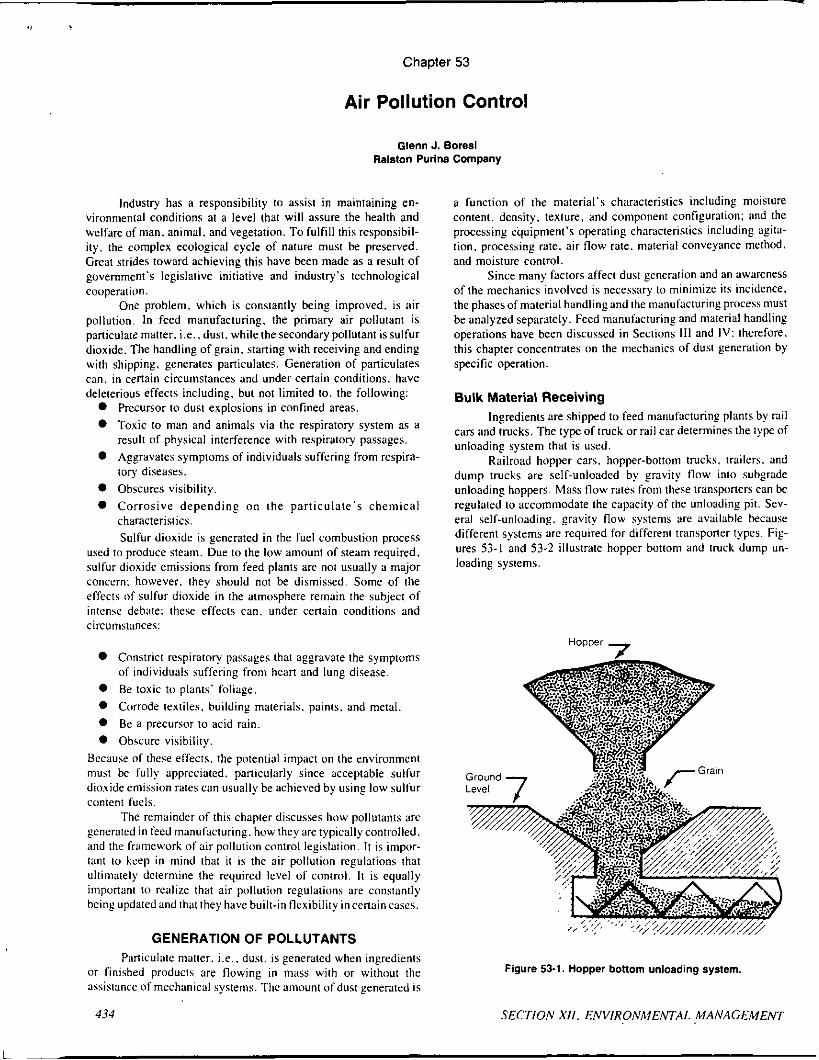
Chapter 53
Air Pollution Control
Glenn J. Boresi Ralston Purlna Company
Industry has a responsibility Io assist in maintaining en- vironmental conditions at a level that will assure the health and welfare of man, animal. and vegetation. To fulfill this responsibil- ity. the complex ecological cycle of nature must be preserved. Great strides toward achieving this have k e n made as a result of govemment's legislative initiative and industry's technological cooperation.
One problem. which is constantly being improved, is air pollution. In feed manufacturing. the primary air pollutant is paniculate matter. i.e., dust. while the secondary pollutant is sulfur dioxide. The handling of grain. staning with receiving and ending with shipping, generates paniculates. Generation of paniculates can. in certain circumstances and under cenain conditions, have deleterious effects including. but not limited to. the following:
0 Precursor to dust explosions in confined areas. 0 Toxic to man and animals via the respiratory system as a
result of physical interference with respiratory passages. 0 Aggravates symptoms of individuals suffering from respira-
tory diseases. 0 Obscures visibility. 0 Corrosive depend ing on the par t iculate 's chemical
characteristics. Sulfur dioxide is generated in the fuel combustion process
used to produce steam. Due to the low amount of steam required. sulfur dioxide emissions from feed plants are not usually a major concern: however. they should not be dismissed. Some of the effects of sulfur dioxide in the atmosphere remain the subject of intense debate: these effects can. under certain conditions and circumstances:
0 Constrict respiratory passages that aggravate the symptoms of individuals suffering from hean and lung disease.
0 Be toxic tu plants' foliage. 0 Corrode textiles. building materials. paints. and metal. 0 Be a precursor to acid rain. 0 Obscure visibility.
Because of these effects. the potential impact on the environment must be fully appreciated. particularly since acceptable sulfur dioxide emission rates can usually be achie\,ed by using low sulfur content fuels.
The remainder of this chapter discusses how pollutants are generated in feed manufacturing. how they are typically controlled. and the f rumewrk of air pollutiun control legislation. I t is inipor- tan1 to kcep in mind that i t is the air pollution regulations that ultimately determine the required level of control. I t is equally imponant to realize that air pollution regulations are constantly being updatedand that they have built-in flexibility incenaincases.
GENERATION OF POLLUTANTS Paniculate matter. Le.. dust. is generated when ingredients
or finished products are flowing in mass with or without the assistance of mechanical systems. The amount of dust generated is
434
a function of the material's characteristics including moisture content. density, texture, and component configuration: and the processing equipment's operating characteristics including agita- tion. processing rate. air flow rate. material conveyance method. and moisture control
Since many factors affect dust generation and an awareness of the mechanics involved is necessary to minimize its incidence. the phases of material handling and the manufacturing process must be analyzed separately. Feed manufacturins and material handling operations have been discussed in Sections 111 and IV: therefore. this chapter concentrates on the mechanics of dust generation by specific operation.
Bulk Material Receiving Ingredients are shipped to feed manufacturing plants by rail
cars and trucks. The type of truck or rail car determines the type of unloading system that is used.
Railroad hopper cars. hopper-bottom trucks. trailers. and dump trucks are self-unloaded by gravity f low into subgrade unloading hoppers. Mass flow rates from these transponers can be regulated to accommodate the capacity of the unloading pit. Sev- eral self-unloading. gravity flow systems are available because different systems are required for different transponer types. Fig- ures 53-1 and 53-2 illustrate hopper bottom and truck dump un- loading systems.
7 Hopper
Ground Level
-Grain
Figure 53-1. Hopper bonom unloading system.
SECTION XII . ENVIRONMENTAL MANAGEMENT

i !
I
I I
I
4
!
lb
Figure 53-2. Truck dump unloading system.
The construction of the unloading pit. type of transporter. material free-fall distance. unloading rate. material characteristics. and ambient conditions are all significant factors contributing to dust generation. Of these six factors. the material characteristics and type of transporter are frequently not controllable by the feed manuhcturer.
Hopper bottom unloading allows greater control over dust generation than truck dumping. as mass flow and free-fall distance can be more strictly regulated. Deep unloading pits used in truck dumping operations to allow for material surge are not necessary for hopper bottom unloading operations because greater mass flow control can be exercised.
In truck dumping operations. the angle of inclination and interpanicle friction govern mass flow. Consequently. the operator cannot effectively control the surging flow. Conversely. in hopper bottom unloading. mass flow can be accurately regulated by using shallou, unloading pits and screw conveyors. as shown in Figure 53-1. This application. termed the choke-feed method. eliminates material free-fall and surging mass flow rates. Since the feed nlanufacturer cannot completely control the type of railcar or truck supplying the plant. both types of transporters must be serviced: however. the choke-feed method minimizes dust generation.
Boxcars emptied by front-end loaders or power shovels donstitute another type of unloading system. As in truck dumping uperations. the material is allowed to free-fall from the transponer inlo the unloading pit. thereby producing a dust cloud. Besides generating dust. this system consumes inordinate manpower. Therefore. if possible. ingredient suppliers should be required to employ self-unloading Iransporters.
CHAPTER 53. AIR POLLUTION CONTROL
Occasionally. ingredients are transported from the rail cars and trucks by pneumatic conveyors. The material is usually blown through a cyclone receiver, which separates the materials from the air. The air is discharged to the atmosphere and the material tu a storage bin. Infrequently. the material is expelled directly into a storage bin and the excess air emitted through a bin vent filter. A vent is required on the storage bin to relieve air displaced by the entering materials.
Bulk Material Conveyance Bulk material is conveyed to storage and processing equip-
ment by conveying mechanisms that include screw conveyors. belt conveyors. pneumatic conveyors. oscillating conveyors. drag con- veyors. bucket elevators. and gravity flow. The type of conveyor. its application, and the operating procedure all greatly affect dust generation.
Screw conveyors are among the oldest and simplest meth- ods, used to move bulk materials. A screw conveyor consists of a rotary screw mounted inside a conveying trough. For each rotation of the screw the material is channeled along the trough by the spiralled flange. A screw conveyor can transport bulk material horizontally or at inclines of 90 degrees. Screw conveyors are easily covered making them dust tight; however. allowance for air displacement must be made. The displaced air should be discharged to an air pollution control device to recover valuable product and tu protect the environment. Screw conveyors are an excellent and simple method of controlling dust.
Belt conveyors are widely used to transport bulk materials due to their simple and inexpensive operating characteristics. They can be troughed o r flat. but are not as adaptable to inclined conveyance as screw conveyors. Also. they are not as easily enclosed as screw conveyors, which results in dustier operations. Therefore. in dust sensitive areas. i t is advisable to use screw conveyors. Also. screw conveyors are more compact than belt conveyors. This characteristic is very important in space limited areas. Thus. belt conveyors can be successfully applied when the material is relatively dust-free and space is not a nliijor factor.
Pneumatic conveyors &'ere originally used to control dust. Some advantages of pneumatic conveying include ease of in- stallation. layout flexibility. multiple feed and discharge points. low maintenance requirements. self-cleaning capability. and dust control. Some disadvantages include high operational cost ctini- pared to mechanical systems. high initial costs that can exceed capital expenditures for a mechanical system. and limited material applicability.
Since pneumatic conveyors operate by blowing or sucking material through a,pipe. dust containment is an inherent property of the system. Dust is generated but is conveyed along with the material. Due to the relative weight of the dust compared to the material. the dust remains suspended in the air when the material is discharged. However. the suspended particles are easily directed to an air pollution device to separate them from the air. The air is discharged to the atmosphere and the dust is returned to the proce Although pneumatic conveyors are en\,ironmcntally desirablc. operating costs may bc prohibitive.
Oscillating conveyors n i w e material by the forward and upward repetitive niotion of a trough. The? can handlc a widc variety of material. can easily he made dust tight. and are relati\,ely compact. By varying the oscillating speed. dust generation can be minimized. Their major disadvantage is that a single drive is effective for a maximum length of unly 100 feet.
Oscillating conveyors. properly operated. can keep dust concentrations Io a niinimuni: however. for long transitions they
135

are not cost competitive with screw and belt conveyors. Also, oscillating conveyors are more operation and maintenance inten- sive then most o f the other systems.
Drag conveyors can he used in many of the same appli- cations as screw conveyors. However, drag conveyors move mate- rial more gently and are relatively self-cleaning. A drag conveyor consists o f a series o f paddles mounted on a drive chain that revolves within a stationary trough. The trough i s easily covered to make i t dust tight. Drag conveyors are more effective in moving material up an incline than screw conveyors: however, an allow- ance should he made for displaced air. Application of an air pollution control device to the displaced air i s necessary to recover product and minimize dust emissions. Although operating costs for drag and screw conveyors are comparable. drag conveyors are usually a more expensive capital and maintenance cost item.
Bucket elevators are used to move material vertically or up steep inclines. They consist of a series o f buckets attached to a drive chain or belt that revolves within a casing. Material is fed into the bottom and discharged at the top. and the buckets are empty on the downward return. Due to the rotary motion o f the system. air currents develop within the casing and generate dust. If the bucket elevator i s operated at too great a speed, spillage and dusting can become intolerable. As with all conveyors, an air pollution control device i s recommended to recover product and minimize dust emissions.
Gravity flow of material requires enclosures such as spouts or chutes. The angle o f inclination and the spouting arrangement (angles. elbows. etc.)determines how muchdust wi l l begenerared. However, dust can he controlled by applying dust tight enclosures and air pollution control devices.
Al l conveyors require dust control. including enclosures and air pollution abatement devices. to recover product and minimize dust emissions. The entire conveyance system should be analyzed to optimize the centralization of the air pollution control device(s). Noteveryconve).orrequires an air pick-uptotransferthedusttothe control device. These pick-ups are selected by establishing key areas (e.g.. transfer and discharge points) and determining their ventilation requirements. Refer to Section 111. Chapter 13. for a discussion o f dust collection systems for materials handling and storage.
Manufacturing Operations After ingredients are received. several operations are em-
ployed. These include ingredient processing, proportioning and mixing. pelleting. extruding or blocking. and possibly. packaging.
Ingredient processing includes grain cleaning and grinding. Grain cleaning removes dockage that includes dust. din. stalks. sticks. stones. stems. and other grains mixed with the bulk in- gredient. Cleaning i s a three-step operation, The first step i s scalping. which employs a coarse mesh screen supported within a dust tisht enclosure. The whole unit either shakes or revolves. Since the velocity of the grain through the screen i s low. the enclosure i s dust tight and there i s no aspiration: therefore. dust control i s not required. The second step i s aspiration. which employs air streams directed perpendicular to dispersed. falling grain. The aspirator removes field dust. chaff. and light trash. Due to the nature o f the unit's operation. large amounts of dust may he generated. The air discharged from the aspirator must be cleansed before being discharged to the atmosphere. Sieving is the final step in the grain cleaning process. The sieve is designed to remove mixed grains and weeds. I t consists o f a series of different sized. meshed screens supporkd within a dust tight enclosure requiring no air pollution control.
Many feed plants use hammermills to grind ingredients. These units accomplish both grinding and air conveyance. Grain is fed into the center of a high-speed rotor where the pivoted hammers move i t to the perimeter screen. The grain i s forced through the screen, usually with the aid of supplemental air. The ground product i s pneumatically conveyed to a cyclone separator or filter receiver that separates the air from the ground ingredient. I t can also be moved using mechanical conveyors and bucket elevators.
In proportioning and mixing. ingredients are conveyed from storage bins to a hopper scale that weighs the batch and feeds i t to a mixer. Dust i s generated when the ingredients are dumped into the hopper scale, which should have a vent fitted with a filter to relieve the displaced air and minimize dust emissions. No other dust control i s required.
Pelleting. extruding. and blocking are methods of producing moist agglomerated particles with little or no dust emissions. However. following pelleting and extruding, cooling or drying i s required. utilizing large air flow rates. Although the dust generated in these operations i s not great. its control i s necessary to prevent product loss. Cyclone collectors are typically used to prevent such loss.
The pelleted or extruded product passes through a shaker to achieve panicle separation before packaging. bulk storage. or bulk shipping. Some dust may be generated during this operation de- pending on product moisture: therefore. a dust tight enclosure is required to prevent product loss.
Bulk Product Shipping The bulk loading o f rail cars or trucks i s similar to bulk
storage operations: however. the amount o f dust generated may be much less due to liquid additions and product forming. Downspouts feed the product into the rail car or truck: however. due to the free-fall and impact o f the product inside the compartment. a dust plume may be generated. Dust control methods include spout jackets. area enclosure and hooding. and ventilation to air pollution control equipment.
Loading of bulk feed into rail cars and trucks can also be accomplished pneumatically. If pneumatic conveyors are used, a filter cloth screen should he applied to the opening to conlain the dust.
Boilers The incomplete combustion of fuel fur steam generation
releases particulates. sulfur oxides. nitrogen oxides. carbon mon- oxide, and hydrocarbons to the atmosphere. Particulates and sulfur dioxide are o f primary concern. The percentages of ash and sulfur in the fuel are directly proportional to the emission of paniculates and sulfur dioxide. Emission levels can be controlled by fuel selection. Natural gas and Nu. 2 fuel oi l are relatively clean burning and usually require noairpollutionequipment. Coal and Nos. 5 and 6 fuel oils are dinier fuels and occasionally require a i r pollution control equipment to clean the tlue gas.
The decision and capability to hum a certain fuel type depends on the relative price of different types of fuel. the capital and operating cost of air pollution control equipment. the USEPA designation of the plant's geographical location, and the applicable regulations. Due to fluctuating fuel prices and Ion1 levels of fuel consumption, i t i s usually advisable fur sniall users to bum the cleaner fuels.
436 SECTION X I I . ENVIRONMENTAL MANAGEMENT
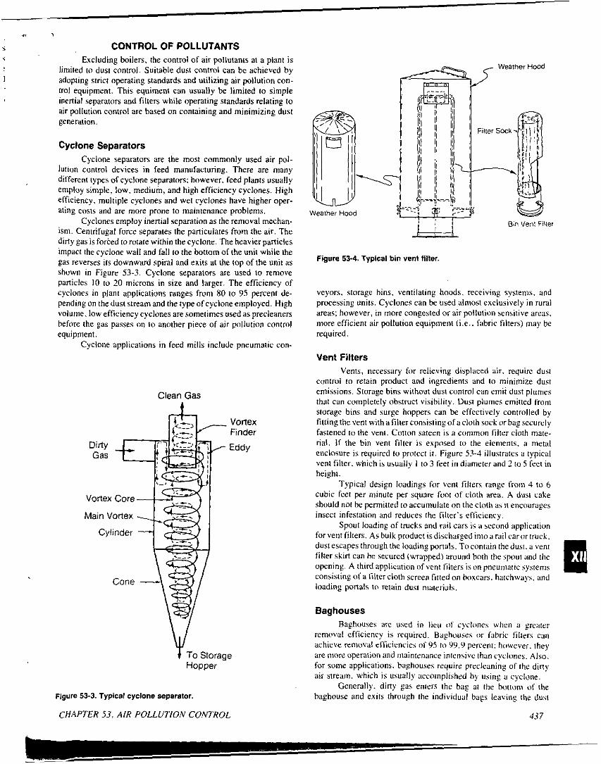
.I , 5 CONTROL OF POLLUTANTS i
I
Excluding boilers. the control of air pollutants a1 a plant is limited to dust control. Suitable dust control can be achieved by adopting strict operating standards and utilizing air pollution con- trol equipment. This equiment can usually he limited to simple inertial separators and filters while operating standards relating to air pallution control are based on containing and minimizing dust generation.
Cyclone Separators Cyclone separators are the most commonly used air pol-
lution control devices in feed manufacturing. There are many different types of cyclone separators; however, feed plants usually employ simple, low, medium, and high efficiency cyclones. High efficiency, multiple cyclones and wet cyclones have higher oper- ating costs and are more prone to maintenance problems.
Cyclones employ inertial separation as the removal mechan- ism. Centrifugal force separates the paniculates from the air. The dirty gas is forced 10 rotate within the cyclone. The heavier particles impact the cyclone wall and fall to the bottom of the unit while the gas reverses its downward spiral and exits at the top of the unit as shown in Figure 53-3. Cyclone separators are used to remove panicles 10 to 20 microns in size and larger. The efficiency of cyclones i n plant applications rdnges from 80 to 95 percent de- pending on the dust stream and the type of cyclone employed. High volume. low efficiency cyclones are sometimes used as precleaners before the gas passes on to another piece of air pollution control equipment.
Cyclone applications in feed mills include pneumatic con-
Clean Gas
Vortex Finder Eddy
Figure 53-3. Typical cyclone separator.
CHAPTER 53. AIR POLLUTION CONTROL
r==G?%J Hood
Figure 53-4. Typlcal bin venl filter,
veyors, storage bins. ventilating hoods. receiving systems. and processing units. Cyclones can he used almost exclusively i n rural areas; however, in more congested or air pollution sensitive areas. more efficient air pollution equipment (i.e.. Fabric filters) may be required.
Vent Filters Vents. necessary for relieving displaced air. require dust
contrvi to retain product and ingredients and lo minimize dust emissions. Storage bins without dust control can emit dust plumes that can completely obstruct visibility. Dust plumes emitted from storage bins and surge hoppers can he dfectively controlled by fittinpthe\'ent withafilterconsislingofacloth sock orbag securely fastened to the vent. Cotton sateen is a common filter cloth mate- rial. If the bin vent filter is exposed to the elenients. a metal enclosure is required to protect i t . Figure 53-4 illustrates a typical vent filter. which is usually I to 3 feet in diameter and 2 to 5 feet in height.
Typical design loadings for vent filters range from 4 to 6 cubic feet per minute per square foot of cloth ared. A dust cake should not be permitted to accumulate on the cloth as it encourages insect infestation and reduces the filter's efficiency.
Spout loading of ~ N C ~ S and rail cars is a second application forventfilters. A$ bulk product isdischarged intoarailcarilrtruck. dust escapes through the loading portuls. Tocontain the dust. a writ filter skirt can be secured (wrapped) around both the spout and the opening. A third application of vent Silters is on pneumitic systems consisting of a filter cloth screen fitted on boxcars. hatchways. and loading ponals to relain dust niaterials,
Baghouses Baghouses are used in lieu (11 cyclones when a greater
remowl efficiency is required. Baghouses or fabric filters can achieve removal efficiencies n S 95 t o 99.9 percent: however. they are more operation and inaintcnance intensive than cyclones. Also. for some applications. haghouses require prrcleaning of the din? air stream. which is usually accomplished by using a cyclone.
Generally. dirty gas enters the hag at the bottom of the haghouse and exits through the individual bags leaving the dust
13 7
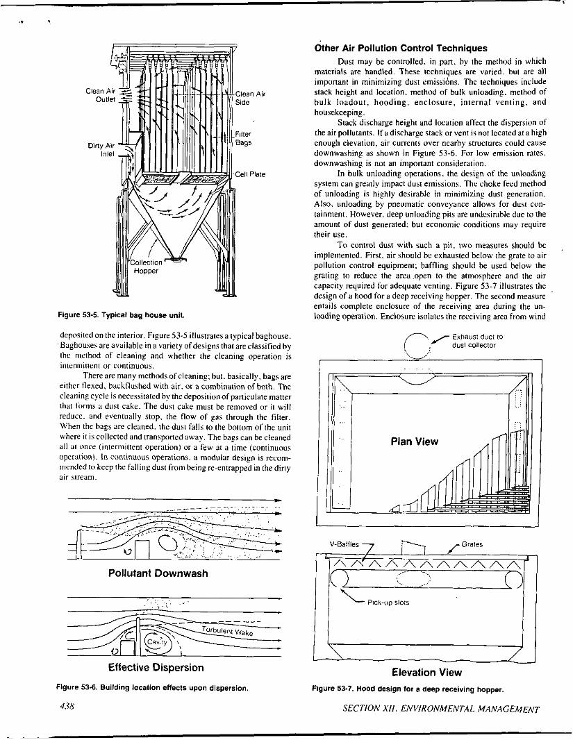
.. I
Figure 53-5. Typical bag house unit.
deposited on the interior. Figure 53-5 illustrates a typical haghouse. Baghouses are available in a variety ofdesigns that are classified by the method of cleaning and u,hether the cleaning operation i s intermittent or continuous.
There are many methods of cleaning; hut. basically, bags are either flexed. hackflushed with air. or a combination of both. The cleanins cycle is necessitated by the deposition o f paniculate matter that fornis a dust cakc. The dust cake must be removed or i t wi l l reduce. and eventually stop. the flow of gas through the filter. When the hags are clcaned. the dust falls to the bottom ofthe unit where i t is collected and transponed away. The hags can he cleaned a l l at once (intermittent operation) or a few at a time (continuous operation). In continuous operations. a modular design i s recom- nicnded to keep the falling dust from being re-entrapped in the diny air stream.
Pollutant Downwash
Effective Dispersion
Figure 53-6. Building location effects upon dispersion.
438
Other Air Pollution Control Techniques Dust may be controlled. in pan. by the method in which
materials are handled. These techniques are varied, hut are a l l imponant in minimizing dust emissihns. The techniques include stack height and location. method o f bulk unloading. method of hulk loadout. hooding. enclosure, internal venting, and housekeeping.
Stack discharge height and location affect the dispersion of the air pollutants. I f a discharge stack or vent i s not located at a high enough elevation, air currents over nearby structures could cause downwashing as shown in Figure 53-6. For low emission rates. downwashing i s not an imponant consideration.
I n bulk unloading operations. the design o f the unloading system can greatly impact dust emissions. The choke feed method of unloading i s highly desirable in minimizing dust generation. Also. unloading by pneumatic conveyance allows for dust con- lainment. However. deep unloading pits are undesirable due to the amount of dust generated: but economic conditions may require their use.
To control dust with such a pit. two measures should be implemented. First. air should he exhausted below the grate to air pollution control equipment: baffling should he used below the grating to reduce the area .open to the atmosphere and the air capacity required for adequate venting. Figure 53-7 illustrates the design o f a hood for a deep receiving hopper. The second measure . entails complete enclosure of the receiving area during the un- loading operation. Enclosure isolates the receiving area from wind
Exhaust duct to dust Collector
V-Baffles
.. ..... . \..
Pick-up 5101s
Elevation View Figure 53-7. Hood design for a deep receiving hopper.
SECTlOh' X I l . EhVIRONMENTAL MAh'AGEMEh'T
.n
currents. thereby allowing effective operation of the deep hopper venting system.
In sensitive air pollution areas. internal venting of cyclones and fabric filters may be warranted. However, the affected internal area should not be frequented by employees. and precautions should be observed to prevent dust explosions (e.g., National Electric Code).
An important practice in minimizing dust is housekeeping. which includes regular cleanup of settled dust and spilled grain in all areas. Neglecting this practice can contribute lo a violation of federal. state. or local regulations depending on meteorological conditions. Poor housekeeping can negate an otherwise good air pollutiun control program.
The above air pollution control techniques are only a few of the many measures that can minimize dust concentrations. It is important to carefully review all designs to ascertain their potential affect on dust generation. The degree of enclosure. hooding. ventilation rate. conveyance method. and material agitation are a few things to consider when reviewing any design.
REGULATIONS Air pollution regulations in the United States are embodied
in a very complex and changing piece of legislation termed the Clean Air Act. The purpose of the Clean Air Act is to realize the national commitment to protect and enhance the nation's air qual- ity. To attain this goal. the National Ambient Air Quality Standards (NAAQS). various national emission standards. and a state and local regulatory framework have been established. Emissions from feed plants do not normally include those pollutants covered by national performance standards. except i n cenain new o r upgraded facilities. Therefore. the following discussion will be limited to the legislation promulgated to attain the NAAQS.
The NAAQS were designated for specified pollutants. in- cluding paniculate and sulfur dioxide. to fulfill two criteria: ( I ) the protection of human health with an adequate margin of safety: and ( 2 ) the protection of public welfare. which includes wildlife. plants. climate. and recreation. To attain or preserve the NAAQS, the follou,ing key programs were adopted under authority of the Clean Air Act:
State Implementation Plans (SIP). 0 Prevention of Significant Deterioration (PSD) Program. 0 Nonattainment Program.
State implementation plans outline the programs to be used toattain the NAAQS within each state. They incorporate both state and local air pollution regulations and make them federally enfurccable.
The purpose of the PSD program is to preserve air quality in areas that are in compliance u,ith the NAAQS. These areas are called "attainment" o r "PSD" areas. They have been sub- categorized in to Class 1. 11. and 111 regions. Class I regions are pristine areas with extremely stringent permitting requirements. such as national parks. Most PSD areas are Class I I and have less stringent pemiitting requirements. Class 111 areas can afford a large increment of deterioration hefore NAAQS are violated. To pre- serve air quality. no Class 111 areas have been designated.
The PSI) prosram requires a preconstruction review of all prujects affecting air quality. If the increase in the mass emission
,
rate of a criteria pollutant is large enough to define the project as a new major source. application of best available control technology (BACT) and an extensive permit review process is required. New minor sources may o r may not require air pollution control. Permit- ting procedures are much less stringent.
The USEPA has identified certain industries and pro- mulgated special regulations applicable to them entitled New Source Performance Standards (NSPS). Grain elevators are in- cluded under the NSPS: however. the definition of a grain elevator usually excludes feed plants. Affected facilities and their new construction must apply the best demonstrated technology (BDT) for air pollution abatement. BDT takes into account air pollution control costs. unlike BACT. The NSPS also establishes minimum criteria for BACT. The NSPS has its own separate body of tegu- lations: however. for the purposes of this text. i t has been discussed under the PSD program to facilitate a simple understanding of complex regulations.
The purpose of the nunattainment program is to achieve compliance with the NAAQS within a specified period of time in those areas that exceed the standards for any of the criteria pollu- tants. However. i t must be understood that attainment and non- attainment status are pollutant specific. That is, an area could be designated as attainment for one pollutant and as nunattainment for another.
Nonattainment regulations are applied to existing sources through control strategies or equipment. The application of control technology to existing sources is defined as reasonably available control technology (RACT). An example of a control strategy is a vehicle inspection and maintenance program. Nonattainment reg- ulations are applied to new major sources in the form of emission offsets and a control technology designated as the lowest achiev- able emission rate (LAER). Offsets are the mandatory net reduction of emissions within the affected area for every institution of a new major source. LAER technology for major sources requires com- pliance with the must stringent emission standard established by the stale or attainment of the most stringent emission level achieved by a source i n the same category. whichever is more stringent. A minor source must comply with the emission standards established for the facility's location and industrial category.
Due to its complexity and the periodic modifications to the Clean Air Act. a more detailed arialysir will not he pursued. The preceding was presented to provide a basic understanding of the Act's structure. To comply with this legislation and its accompany- ing regulations. the feed manufxturershould refer to the applicable state's air pollution regulations and seek the advice of an en- vironmental specialist or the state's air pollution control agency. These organizations can advise on the specific regulations. their flexibility (e.€.. bubble policy) and possible cost saving mechan- isms (e .€ . , emission reduction credits).
CITED REFERENCES USEPA. Office of Air and Waste Management, Office of Air
Quality Planning and Standards. 1980. Compilation of Air Pollutant Emission Factors, Third Edition, Publication No. AP-42, USEPA, Research Triangle Park, North Carolina.
Wark. K. and Cecil F. Warner, 1976, Air Pollution: Its Origin and Control, Harper 8 Row Publishers, Inc., New York. New York.
CHAPTER S3. AIR POLLUTION CONTROL 43Y
L e- ~-