reference manualregion 7 automatic tank monitoring & line leak detection reference manual...
TRANSCRIPT

.....................Region 7
AUTOMATIC TANK MONITORING & LINE LEAK DETECTION
REFERENCE MANUAL
Author: Bjorn Brinkman,Environmental EngineerEPA, Region 7, 913-551-7761

TLS-250Automatic Tank Gauging System
VEEDER-ROOT125 Powder Forest Dr.Simsbury, CT 06070Tel: (203) 651-2700
Evaluator: MRI - 05/14/93
System Description: The TLS-250 is capable of sensing product loss assmall as 0.2 gph. The leak detect routine is conducted while no fueling istaking place and no bulk deliveries are being made. The leak detectionmode can be operated manually or set automatically for times when thefacility is closed. It can be set to test a single tank or all tanks in a system.The TLS also checks itself and the fuel prior to and during a test for nineseparate conditions including low inventory, recent bulk delivery andequipment problems which could cause a false test failure. The TLSsystem is capable of handling 8 probes. The TLS-250 Plus! uses differentprobes and can detect a leak of 0.1 gph. The TLS-250i uses sensors tomonitor interstitial areas.
Certification: 0.2 gph with PD = 99% and PFA = 0.1% 0.1 gph with Plus! system
Tank Capacity: Max. 15,000 gal
Test Period: Min. 2 hrs with tank 50 - 95% full Min. 3 hrs with Plus! system
Limitations: - No dispensing or delivery during test- Not evaluated using manifold tanks- Not capable of continuous monitoring- Not equipped to monitor product lines

SAMPLE REPORTS TLS-250
1. Display Inventory Information (NORMAL MODE)
a. Depress FUNCTION until desired functionb. Depress TANK until desired tank
2. Print Inventory Information (NORMAL MODE)
a. Depress PRINT ; information for all tanks in system.
3. Leak or Sensor Monitor Report (NORMAL MODE)
a. Depress FUNCTION until “Leak Rate (gal/hr)” b. Depress PRINT ; information for
all tanks in system
- 2 -

SAMPLE REPORTS TLS 250
(cont) 4. Alarm History Report (DIAGNOSTIC MODE)
a. Depress FUNCTION until diagnostic code “8"b. Depress PRINT, shows the last three occurrences
of each type of alarm for this tank
5. Inventory Increase Report (NORMAL MODE)
a. Depress FUNCTION until “Delivery Volume”b. Depress PRINT ; shows last delivery
- 3 -

TLS-350Automatic Tank Gauging & Electronic Line Leak Detection System VEEDER-ROOT125 Powder Forest Dr.Simsbury, CT 06070Tel: (203) 651-2700
Evaluator: MRI - 03/14/95 & 06/10/96 (CSLD)
System Description: The TLS-350 and the TLS-350R (business inventory reconciliation) are monitoring systems that can be upgradedto provide continuous statistical leak detection (CSLD) and line leakdetection if the appropriate options are added to the console. The CSLDoption provides continuous tank leak detection without operational shutdown. The system can also operate on various software, depending on theUST system. The TLS-350R is able to automatically gather inventoryinformation and reconcile totals at the end of each shift, day and period.Without the CSLD option, the TLS-350 can detect a leak of 0.1 gph;however, the UST system must be idle during the test. With the CSLDoption, it is certified at 0.2 gph and can be used to test manifoldedsystems. Three line leak detection options are available:
Volumetric Line Leak Detection (VLLD) Pressurized Line Leak Detection (PLLD) & Wireless Pressurized Line Leak Detection (WPLLD);
all can detect 3, 0.2 and 0.1 gph. The TLS-350 is also capable ofmonitoring groundwater and vapor sensors. The console features a built-in beeper and warning lights for alarm conditions and can beprogrammed to shut down pumps. You can verify which options areincluded in the system by scrolling thru the functions listed on theconsole display.

TLS-350(CONT)
Certification: TANK GAUGING 0.1 gph with PD = 99% and PFA = 1% With CSLD 0.2 gph with PD = 100% and PFA = 0% LINE TEST 3, 0.2 & 0.1 gph with PD = 100% and PFA = 0%
Tank Capacity: Max. 15,000 gal Max. 38,170 gal for all manifolded tanks with CSLD
Test Period: TANK GAUGING Min. 3 hrs with tank 95% full for 0.1 gph test Min. 2 hrs with tank 50 - 95% full for 0.2 gph test With CSLD No down time LINE TEST (Depends on probe series) 3.0 gph - 14 sec to 1 min 0.2 gph - 6 to 45 min 0.1 gph - 14 to 45 min
Limitations: W/O CSLD option - No dispensing or delivery during test - Not evaluated using manifolded tanks W/O LLD option - Not equipped to monitor product lines
-2-
SAMPLE REPORTSTLS-350
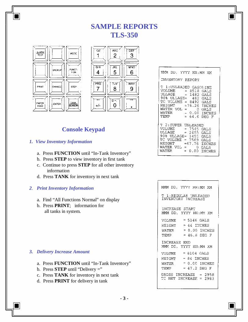
Console Keypad
1. View Inventory Information a. Press FUNCTION until “In-Tank Inventory” b. Press STEP to view inventory in first tank c. Continue to press STEP for all other inventory information d. Press TANK for inventory in next tank
2. Print Inventory Information a. Find “All Functions Normal” on display b. Press PRINT ; information for all tanks in system.
3. Delivery Increase Amount a. Press FUNCTION until “In-Tank Inventory” b. Press STEP until “Delivery =” c. Press TANK for inventory in next tank d. Press PRINT for delivery in tank
- 3 -

SAMPLE REPORTSTLS-350
(cont)
4. Tank Leak Test Results a. Press FUNCTION until “In-Tank Test Results” b. Press PRINT for all tank leak tests
5. CSLD Test Results
a. Press FUNCTION until “CSLD Test Results” b. Press PRINT for CSLD results in all tanks
6. Pressurized Line Leak Detection Tests (PLLD) a. Press FUNCTION until “Pressure Line Results” b. Press PRINT for results in all lines
- 4 -

SAMPLE REPORTSTLS-350
(Cont)
7. PLLD History Reports
a. Press FUNCTION until “Pressure Line Results” b. Press STEP until “Press Print for History” c. Press PRINT for history; last 3 gph, first 0.2 gph & first 0.1 gph results for each month
8. Wireless Pressurized Line Leak Detection Tests (WPLLD)
a. Press FUNCTION until “WPLLD Line Results” b. Press PRINT for results of all lines
9. WPLLD History Reports
a. Press FUNCTION until “WPLLD Line Results” b. Press STEP until “Press Print for History Report” c. Press PRINT for history; last 3 gph, first 0.2 gph & first 0.1 gph results for each month
- 5 -
SAMPLE REPORTSTLS-350
(Cont)
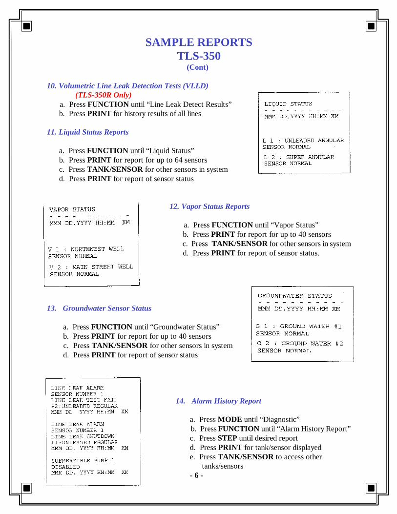
10. Volumetric Line Leak Detection Tests (VLLD) (TLS-350R Only) a. Press FUNCTION until “Line Leak Detect Results” b. Press PRINT for history results of all lines
11. Liquid Status Reports a. Press FUNCTION until “Liquid Status” b. Press PRINT for report for up to 64 sensors c. Press TANK/SENSOR for other sensors in system d. Press PRINT for report of sensor status
12. Vapor Status Reports a. Press FUNCTION until “Vapor Status”
b. Press PRINT for report for up to 40 sensors c. Press TANK/SENSOR for other sensors in system
d. Press PRINT for report of sensor status.
13. Groundwater Sensor Status a. Press FUNCTION until “Groundwater Status” b. Press PRINT for report for up to 40 sensors c. Press TANK/SENSOR for other sensors in system d. Press PRINT for report of sensor status
14. Alarm History Report a. Press MODE until “Diagnostic” b. Press FUNCTION until “Alarm History Report” c. Press STEP until desired report d. Press PRINT for tank/sensor displayed e. Press TANK/SENSOR to access other tanks/sensors - 6 -

SAMPLE REPORTSTLS-350
(Cont)
15. Leak History Report a. Press MODE until “Diagnostic” b. Press FUNCTION until “In-Tank Leak Result” c. Press STEP until “Print Leak History” d. Press PRINT
-7 -

EMC ENVIRONMENTALMANAGEMENT CONSOLE
Automatic Tank Gauging & Electronic Line Leak Detection System GILBARCO7300 West FriendlyGreensboro, NC 27420Tel: (910) 547-5000
Evaluator: MRI - 05/14/93
System Description: The EMC is manufactured by the same companythat manufactures the TLS-350. It operates and looks similar to theTLS-350. Refer to the TLS-350 information sheets for system descriptionand instructions for obtaining reports.
Certification: TANK GAUGING 0.1 gph with PD = 99% and PFA = 1% With CSLD 0.2 gph with PD = 100% and PFA = 0% LINE TEST 3, 0.2 & 0.1 gph with PD = 100% and PFA = 0%
Tank Capacity: Max. 15,000 gal Max. 38,170 gal for all manifolded tanks with CSLD
Test Period: TANK GAUGING Min. 3 hrs with tank 95% full for 0.1 gph test Min. 2 hrs with tank 50 - 95% full for 0.2 gph test With CSLD No down time

WILCOFuel Management and Compliance Service Receiver
SIMMONS106 East Main StreetRichardson, TX 75081Tel: (800) 848-8378
Keypad/Display Unit Evaluator: S.S.G.Associates - 10/28/95 ATG Probe/Transmitter System Description: The Wilco system employs radio and modemcommunications technology to connect on-site monitoring equipment tothe Simmons Cental Monitoring Center. Technicians collect and processdata, monitor and respond to alarms and generate compliance reports.The Wilco ATG probe uses micro-impulse radar technology to measuretank levels and then transmits data via radio signal to a remote receiverlinked to the Wilco Control Panel. The Wilco control panel with userkeypad and display unit then sends data between the business andSimmons central monitoring center via existing telephone lines.Inventory, sales and delivery data are then used to produce SIR results.Sales and deliveries must be entered manually thru the keypad. Optionsinclude leak detection sensor and overfill alarms.
Certification: SIR 5.7 L.M. version; 0.2 & 0.1 GPH with PD = 99% & PFA = 1%
Tank Capacity: 45,000 gal.; 2, 3 or 4 tank manifolded systems
Test Period: Min. 26 days
Limitations: Data collection only

WILCOKeypad Operation
Keypad/Display Unit Flowchart of Wilco Menu
1. Tank Inventory a. Press “Menu” until Tank Data b. Press “Next” for Volume, Level, Water or Ullage c. Press “Tank/Hose” for different tanks in system
2. Alarm List
a. Press “Menu” until Alarm List b. Press “Next” for each alarm i. alarm description will flash on and off to indicate alarm has not been acknowledged ii. if alarm status is still present, second line will indicate “ACTIVE” iii. if alarm status is not present, second line will indicate “CLEARED”
3. Self-Test (system functioning properly)
a. Press “Menu” until Self-Test b. Press “Next”; enter passcode (1234) i. Display will show SELFTEST OK if functioning properly ii. Display will show SELFTEST FAIL or PRESS SERVICE if not functioning properly
4. Overfill Alarm Check a. Initiate Self-Test, alarm should sound; if not, no overfill alarm b. Press “Cancel” to silence alarm
- 2 -

TS-1000 & 2000Automatic Tank Gauging & Electronic Line Leak Detection System INCONP.O.Box 638Saco, ME 04072Tel: (207) 283-0156
Evaluator: Ken Wilcox Associates - 08/05/92
System Description: The TS-1000/2000 is a monitoring system that cantest and gauge 2 or 4 tank systems. In addition, the TS-1000/2000 canbe optionally equipped with up to 8 leak detection sensors to supportinterstitial, sump, vapor and groundwater monitoring. Alarms can besetup to sound audibly or control relay contacts for high productlevels, high water levels and tank leaks. An optional relay outputBriteBox accessory unit may be configured to shut-off product dispenserpumps or to turn on/off other devices. The system can also be equippedwith optional TS-LLD line leak detection software. Reports are obtainedin the same manner as the RLM 5000.
Certification: TANK GAUGING 0.2 gph with PD = 99.9% and PFA = 0.1% LINE TEST 3, 0.2 & 0.1 gph with PD = 100% and PFA = 0%
Tank Capacity: Max. 15,000 gal Test Period: Min. 5 hrs with tank 50 - 95% full (TS-1000) Min. 3 hrs with tank 50 - 95% full (TS-2000)
Limitations: - No dispensing or delivery during test - Not evaluated using manifolded tanks

SAMPLE REPORTSTS-1000
Reports Available
1. Inventory 2. Reconciliation3. Delivery 4. Delivery History5. Leak Test 6. Leak Time Estimate7. Alarm 8. Alarm History9. Line Test 10. Line Test History
11. Alarm Status and Configuration12. System Configuration13. Tank Configuration
Console Keypad
1. To Print Desired Report a. Press REPORT key b. Press UP or DOWN until desired report c. Press ENTER d If prompted, enter tank number or 0 for all tanks e. Press ENTER to print report
Inventory Report - 2 - Leak Test Report

SAMPLE REPORTS TS-1000
(cont)
Alarm Report
Delivery Report Delivery History Report
Alarm History Report - 3 -

TS-1001
Automatic Tank Gauging & Electronic Line Leak Detection System INCONP.O.Box 638Saco, ME 04072Tel: (207) 283-0156
Evaluator: Ken Wilcox Associates - 09/05/97
System Description: The TS-1001 can monitor product in up to 4 tanksand also monitor up to 12 leak detection sensors internally. In addition,the TS-1001 can be optionally equipped with 1 or 2 external sensorexpansion modules for an additional 8 or 16 sensor inputs capable ofmonitoring double walled tanks, containment sumps, dispenser pans, andvapor or groundwater monitoring wells. Alarms can be setup to soundaudibly or control relay contacts for high product levels, high waterlevels and tank leaks. The console may also be configured to shut-offproduct dispenser pumps or to turn on/off other devices. Optionalequipment includes overfill alarms, interface with line leak detection (TS-LLD) and SCALD (Statistical and Continuous Automatic LeakDetection; not 3rd party certified) software. (See TS-2001 for sample reports)
Certification: TANK GAUGING 0.2 & 0.1 gph with PD = 99.9% and PFA = 0.1% 0.2 gph with (LL2 probe) Tank Capacity: Max. 15,000 gal (30,000 gal with LL2 probe) Test Period: Min. 5 hrs (average time to collect quality data) Can be tested at less than 50% capacity
Limitations: - No dispensing or delivery during test - Not evaluated using manifolded tanks

TS-2001
Automatic Tank Gauging & Electronic Line Leak Detection System INCONP.O.Box 638Saco, ME 04072Tel: (207) 283-0156
Evaluator: Ken Wilcox Associates - 09/05/97
System Description: The TS-2001 can monitor product in up to 8 tanksand also monitor up to 24 leak detection sensors internally. In addition,the TS-2001 can be optionally equipped with 1 or 2 external sensorexpansion modules for an additional 8 or 16 sensor inputs capable ofmonitoring double walled tanks, containment sumps, dispenser pans, andvapor or groundwater monitoring wells. Alarms can be setup to soundaudibly or control relay contacts for high product levels, high waterlevels and tank leaks. The console may also be configured to shut-offproduct dispenser pumps or to turn on/off other devices. Optionalequipment includes overfill alarms, interface with line leak detection (TS-LLD) and SCALD (Statistical and Continuous Automatic LeakDetection; not 3rd party certified) software.
Certification: TANK GAUGING 0.2 & 0.1 gph with PD = 99.9% and PFA = 0.1% 0.2 gph with (LL2 probe) Tank Capacity: Max. 15,000 gal (30,000 gal with LL2 probe) Test Period: Min. 5 hrs (average time to collect quality data) Can be tested at less than 50% capacity
Limitations: - No dispensing or delivery during test - Not evaluated using manifolded tanks

SAMPLE REPORTSTS-1001/2001
1. To Print Desired Report a. Press REPORT key b. Press DOWN/SPACE for more options c. Press menu keys (M1 - M4) to make selection d. Press enter to print
Console Keypad
2. To Print Inventory Report a. Press REPORT key b. Press M 1 c. Press M 4 d. Press enter to print
3. To Print Inventory Summary Report a. Press REPORT key b. Press M 1 c. Press M 2 d. Press enter to print
- 2 -

SAMPLE REPORTSTS-1001/2001
(cont)
4. To Print Leak Test Report 5. To Print SCALD Test Report a. Press REPORT key a. Press REPORT key b. Press M 4 b. Press M 4 c. Press M 2 c. Press M 3 d. Press M 2 (M 3 for history report) d. Press desired M e. Press M 1
- 3 -

SAMPLE REPORTSTS-1001/2001
(cont)
6. To Print Line Compliance Report 7. To Print Alarm/Sensor Reports a. Press REPORT key a. Press REPORT key b. Press M 3 b. Press DOWN/SPACE key c. Press M 1 (M 3 for history report) c. Press M 2 (M1 for sensors) d. Press M 1 d. Press desired M key report
- 4 -

RLM 5000Automatic Tank Gauging System
Red JacketMarley Pump Co.9650 Alden Rd.Lenexa, KS 66215Tel: 913 541-2985
Evaluator: KWA - 04/02/91
System Description: The RLM 5000 operates as the central processingunit and data collection center for leak detection and inventorymanagement. It collects level and temperature data from up to eightmagnetostrictive level probes and computes various volumetric quantities,correcting all volumes for temperature. The operator may choose fromamong various reports as well as generate a complete set of inventory,operation and leak detection reports. These reports may be printed ondemand or prescheduled. All alarms generate reports immediately andmay be programmed to activate one of the two relay outputs. The RLM5001 adds the feature of vapor and liquid detection sensors.
Certification: 0.2 gph with PD = 100% and PFA = 0%
Tank Capacity: Max. 15,000 gal Test Period: Min. 3 hrs with tank 50 - 95% full
Limitations: - No dispensing or delivery during test - Not evaluated using manifolded tanks - Not capable of monitoring product lines - Not capable of continuous monitoring

SAMPLE REPORTS RLM 5000
1. Inventory Report (non- temp comp)
a. Press RPRT key b. Press UP or DN key till “Inventory” c. Press ENTER key d. Press 1 - 8 for desired tank or 0 for all tanks e. Press ENTER key
2. Reconciliation Report ( temp comp)
a. Press RPRT key b. Press UP or DN key till “Reconcil” c. Press ENTER key d. Press 1 - 8 for desired tank or 0 for all tanks e. Press ENTER key
3. Delivery Report
a. Press RPRT key b. Press UP or DN key till “Delivery” c. Press ENTER key d. Press 1 - 8 for desired tank or 0 for all tanks e. Press ENTER key
4. Delivery History Report (if programmed)
a. Press RPRT key b. Press UP or DN key till “Del Hist” c. Press ENTER key d. Press 1 - 8 for desired tank or 0 for all tanks e. Press ENTER key
5. Leak Test Report
a. Press RPRT key b. Press UP or DN key till “Leak” c. Press ENTER key d. Press 1 - 8 for desired tank or 0 for all tanks e. Press ENTER key
- 2 -

SAMPLE REPORTSRLM 5000
(Cont)
6. Leak Estimate Report (length of test)
a. Press RPRT key b. Press UP or DN key till “Leak Est” c. Press ENTER key d. Press 1 - 8 for desired tank or 0 for all tanks e. Press ENTER key
7. Alarm History Report
a. Press RPRT key b. Press UP or DN key till “Alarm Hist” c. Press ENTER key d. Press 1 - 8 for desired tank or 0 for all tanks e. Press ENTER key; last 50 alarms
8. Alarm Status Report (current alarms)
a. Press RPRT key b. Press UP or DN key till “Alarm Stat” c. Press ENTER key d. Press 1 - 8 for desired tank or 0 for all tanks e. Press ENTER key
9. System Setup Report
a. Press RPRT key b. Press UP or DN key till “Setup” c. Press ENTER key d. Press 1 - 8 for desired tank or 0 for all tanks e. Press ENTER key
10. Tank Setup Report
a. Press RPRT key b. Press UP or DN key till “Tank set up” c. Press ENTER key d. Press 1 - 8 for desired tank or 0 for all tanks e. Press ENTER key
- 3 -

RLM 9000Automatic Tank Gauging & Electronic Line Leak Detection System
Red Jacket Marley Pump Co.9650 Alden Rd.Lenexa, KS 66215Tel: 913 541-2985
Evaluator: KWA - 04/02/91
System Description: The RLM 9000 is a single console unit thatincorporates the operational properties of the PPM 4000 and the RLM5000. Refer to the individual information sheets for additional systemdescription and sample reports.
Certification: TANK GAUGING 0.2 gph with PD = 100% and PFA = 0% LINE TEST 3, 0.2, 0.1 gph with PD = 100% and PFA = 0%
Test Period: TANK GAUGING Min. 3 hrs with tank 50 - 95% full LINE TEST 3 gph - 1 min 0.2 gph - 10 min 0.1 gph - 2.5 hrs
Limitations: Refer to individual sheets for PPM 4000 & RLM 5000

ST 1400/1800Automatic Tank Gauging & Electronic Line Leak Detection System
Red JacketMarley Pump Co.9650 Alden Rd.Lenexa, KS 66215Tel: 913 541-2985
Evaluator: ADA Technologies, Inc. - 09/30/92
System Description: The ST1400/1800 controllers are electronic tankgauging devices used for leak detection and inventory management. Thecontrollers can collect level and density data from 4 (ST1400) or 8(ST1800) ultrasonic inventory sensors and compute various volumetricquantities, correcting all volumes for temperature. The systems haveprogrammable alarm thresholds to alert the operator of various alarmconditions. The system is also capable of storing at least the last 33events of any particular report. The ADD (accumulative data diagnostics)option adds the capability of continuous leak detection (not 3rd partied).The ST1401/1801 systems add sensor monitoring for interstitial areas,wells and sumps. The ST1400L/1800L add the capability of line leakdetection with positive pump shut down.
Certification: TANKS: 0.2 & 0.1 gph PIPING: 3, 0.2 & 0.1 gph
Capacity: TANKS: Max. 18,000 gal PIPING: Max. 55.1 gal Test Period: Min. 2.5 hrs with tank 50 - 95% full (0.2 gph) (W/o ADD) 95 - 100% full (0.1 gph)
Limitations: - No dispensing or delivery during test (w/o ADD) - Not evaluated using manifolded tanks

SAMPLE REPORTSST 1800
DISPLAY OPTIONS*
1. Product Height 2. Gross Volume 3. Ullage 4. Water Height 5. Product Temperature 6. Report History 7. Product Dispensed 8. System Status 9. Leak Detection *Press “E” to get to “SELECT DISPLAY”
CONSOLE DISPLAY
1. View Display Options (at SELECT DISPLAY) a. Press desired display option keypad # b. Press 88or 99key to view remaining tanks
2. View History Reports (including leak test)
a. Press 6 b. Press ºº to scroll to desired report c. Press 88or 99 key to scroll to “reserved report number” d. Press º or » to view info
3. Print Inventory Report (green ‘OL’ indicator light must be on)
a. Press P key for all tanks i. For only one feature, press desired option keypad # ii. Press P 4. Print History Reports (green ‘OL’ indicator light must be on) a. Press 6 b. Press ºº to scroll to desired report c. Press P d. Press 88or 99 key to enter “beginning” date e. Press E f. Press 88or 99 key to enter “ending” date e. Press E to begin printing -2-

AUTOIISTIK II & JR Automatic Tank Gauging & Electronic Line Leak Detection System
EBW2814 McCracken Ave.Muskegon, MI 49441Tel: 616 755-1671
Evaluator: Ken Wilcox Ass. - 08/20/93
System Description: The AUTO/STIK II and JR.series are electronic monitoring devices capable of tracking inventory,detecting leaks and providing alarm warnings. The systems can also beequipped with a continuous 24 hour leak detection option; however thisoption does not accumulate data during intermittent still times as mostsystems do, but continually starts a leak test at still times and ends theleak test only after a 30 minute still time. A leak rate for one test periodis calculated by combining still period leak tests thru four consecutivedays. The AUTO/STIK II can be equipped with the electronic line leakdetection option which can monitor 1 to 8 pressurized lines. TheATUO/STIK II is capable of monitoring 1 to 16 tanks for leak detection,1 to 64 liquid sensors and 1 to 56 relay outputs. The JR series arecapable of handling the number of tanks indicated on the model # andare limited to the amount of sensors and relay outputs they provide.
Certification: 0.1 gph with PD = 98.3% and PFA = 1.7%
Tank Capacity: Max. 15,000 gal Test Period: Min. 4 hrs with tank 50 - 95% full
Limitations: - No dispensing or delivery during test (even w/CLD) - Not evaluated using manifolded tanks - Not capable of monitoring product lines (JR series)

SAMPLE REPORTSAUTOIISTIK
1. Printing Reports
a. Depress PRINT REPORTS b. Depress desired report or MORE c. Continue to press MORE until desired report d. Depress desired report e. Depress ALL or enter desired tank # (01, 02, etc.) f. Depress PRINT
2. Print Inventory Information (Status Report)
a. Depress PRINT REPORTS b. Depress STATUS REPORT c. Depress ALL or enter desired tank # (01, 02, etc.) e. Depress PRINT
3. Print Leak Report
a. Depress PRINT REPORTS b. Depress MORE c. Depress LEAK REPORT d. Depress ALL or enter desired tank # (01, 02, etc.) e. Depress PRINT
4. Print Line Leak Report a. Depress PRINT REPORTS b. Depress MORE - MORE - MORE -MORE c. Depress LINE LEAK REPORT d. Depress ALL or enter desired tank # (01, 02, etc.) e. Depress PRINT
- 2 -

EECO SYSTEM1000 SERIES
Automatic Tank Gauging
EMCO Electronics114-300 Mackenan DrCary, NC 27511Ph# 919 460-6000
Evaluator: Midwest Research Institute - 04/29/94
System Description: The EECO 1000 functions in the same manner asthe EECO 2000 but does not monitor product lines or external sensors.It is strictly a tank management system designed to monitor up to eighttanks. Tank leak tests will start automatically after deliveries or canprogrammed to start at a selected time daily, weekly or monthly. Asegmented leak detection (SLD) option is available to providecontinuous tank leak detection; however, it is not 3rd party certified.
Refer to the EECO 2000 information sheets for additional systemdescription and instructions to obtain reports.
Certification: 3.0, 0.2 & 0.1 gph
Tank Capacity: Max. 15,000 gal Test Period: Min. 1 hrs with tank 50 - 95% full
Limitations: - Not evaluated using manifolded tanks - No dispensing or delivery during test - Does not monitor product lines - Does not monitor external sensors

EECO SYSTEM 1500 SERIES
Automatic Tank Gauging & Sensor Detection System
EMCO Electronics114-300 Mackenan DrCary, NC 27511Ph# 919 460-6000
Evaluator: Midwest Research Institute - 04/29/94
System Description: The EECO 1500 functions in the same manner asthe EECO 2000 but does not monitor product lines electronically. TheEECO 1500 system is able to monitor product lines by the use ofinterstitial sensors. Monitoring sensors can also be used for dispenserpans, sumps and liquid/vapor wells. The EECO 1500 managementsystem is designed to monitor two and four tank systems. Tank leak testswill start automatically after deliveries or can programmed to start at aselected time daily, weekly or monthly. A segmented leak detection (SLD)option is available to provide continuous tank leak detection; however, itis not 3rd party certified.
Refer to the EECO 2000 information sheets for additional systemdescription and instructions to obtain reports.
Certification: 3.0, 0.2 & 0.1 gph
Tank Capacity: Max. 15,000 gal Test Period: Min. 1 hrs with tank 50 - 95% full
Limitations: - Not evaluated using manifolded tanks - No dispensing or delivery during test

EECO SYSTEM 2000 SERIES
Automatic Tank Gauging & Electronic Line Leak Detection System
EMCO Electronics114-300 Mackenan DrCary, NC 27511Ph# 919 460-6000
Evaluator: Midwest Research Institute - 04/29/94
System Description: The EECO 2000 is designed to monitor up to eighttanks, 24 EECO Choice sensors and eight pressurized lines. Tank leaktests will start automatically after deliveries or can programmed to startat a selected time daily, weekly or monthly. A segmented leak detection(SLD) option is available to provide continuous tank leak detection;however, it is not 3rd party certified. The sensors are designed to detectfuel and water in secondary containment vessels, sumps, dispenser pans,and monitoring wells. When alarm conditions occur, audible or displaylights will be activated. The event is then written into the history log. TheLine Leak Detector option provides product line leak detection at 3, 0.2& 0.1 gph. Leaks exceeding the ‘pump shutoff’ threshold will disabledsubmersible pumps. Product line leak tests can occur automatically ormanually.
Certification: TANKS: 0.2 & 0.1 gph PIPING: 3, 0.2 & 0.1 gph
Tank Capacity: Max. 15,000 gal Test Period: Min. 1 hrs with tank 50 - 95% full
Limitations: - Not evaluated using manifolded tanks - No dispensing or delivery during test - Must have LLD option for product line testing

SAMPLE REPORTSECCO 2000
1. View Display Functions (to print reports; press PRINT prior to the following) a. Press DISPLAY b. Press STATUS, HISTORY or LEAK TEST c. Press ENTER e. Press 99 to scroll thru menu selection f. Press ENTER when desired menu g. Continue to press 99 for desired submenu h. Press ENTER when desired submenu i. Press CANCEL to exit menu level 2. Print Inventory Status 4. Print Tank Leak Test History a. Press [PRINT] [STATUS][ENTER] a. Press [PRINT] [LEAK TEST][99] [ENTER] [ENTER][99][99][99][ENTER]
3. Print Event History a. Press [PRINT][HISTORY] [ENTER] [9] [ENTER]
- 2 -

PETROSONIC IIIAutomatic Tank Gauging System Petro Vend6900 Santa Fe DriveHodgkins, IL 60525Tel: (708) 485-4200
Evaluator: Underwriters Laboratories, Inc. - 11/04/94
System Description: The Petrosonic III is a microprocessor-based system capable of monitoring up to eight probes. The controllerinterprets probe data, converts the product level measurements intovolume measurements and produces reports. The controller recordsalarms, such as low product, high water, overfill and theft. The controlleralso functions as a leak indicator by continuously watching for extremelysmall changes in product level. This is not leak testing, but productvariances. The Petrosonic III has alarm inputs you can connect toexternal devices such as hydrocarbon detectors or alarm bells. Thesystem has three modes of operation; privileged, non-privileged andstandby. If the system is in the privileged mode, you must have an accesscode. Default code is HELLO.
Certification: 0.2 gph with PD = 99.07% and PFA = 0.93%
Tank Capacity: Max. 15,000 gal Test Period: Min. 4 hrs with tank 50 - 95% full
Limitations: - No dispensing or delivery during test - Not evaluated using manifolded tanks - Not capable of monitoring product lines - Not capable of continuous monitoring

SAMPLE REPORTSPETROSONIC III
REPORT NAME FUNCTION #
Status 1
Inventory 2
Deliverys 3
Variation 4 1 2 3 PR
Alarms 7 4 5 6 TM
Tank Info 8 7 8 9 AC
Tank Leak Test 53 CL 0 EN CN
Access #’s for Reports Console Keypad
ALL REPORTS ARE OBTAINED IN THE FOLLOWING MANNER:
1. Printing Reports a. Press ACCESS b. Press ENTER; console displays ‘non-privileged’ followed by ‘display command > 0' c. Enter Access # for desired report (above) d. Press PRINT e. Press ENTER for report on all tanks
2. Print List of Keypad Commands (Help) a. Press ACCESS b. Press ENTER c. Press PRINT d. Press ENTER
3. Abort Command
a. Press CANCEL b. Press ACCESS
- 2 -

SAMPLE REPORTSPETROSONIC III
Inventory Report
Status Report
* Active Flag (alarm condition)
Delivery Report
- 3 -

SAMPLE REPORTSPETROSONIC III
Leak Test Report
Leak Test Report is a subset of Messages Report
Alarms Report
- 4 -

SiteSentinelModel II
Automatic Tank Gauging System
PETRO VEND6900 Santa Fe DriveHodgkins, IL 60525Ph# 708 485-4200
Evaluator: Underwriters Lab., Inc. - 11/04/94
System Description: The SiteSentinel is a microprocessor-based systemcapable of monitoring probes and sensors. Each SiteSentinel system hasone controller to manage operations and can be upgraded with modulesto incorporate additional probe and sensor capability. Up to eightmodules can be connected for a total of 128 probes and sensors.Inventory and system reports are available anytime and can be scheduledto print automatically. Built-in sound and light alarms can signal anysystem event. The SiteSentinel has three modes of operation: privileged,non-privileged and restricted. If the system is in the privileged mode,you must have the password. The default password is HELLO.
Certification: 0.1 & 0.2 gph
Tank Capacity: Max. 15,000 gal Test Period: Min. 2 hrs (0.2 gph) with tank 50 - 95% full Min. 4 hrs (0.1 gph) with tank 90% full
Limitations: - No dispensing or delivery during test - Not evaluated using manifolded tanks - Not capable of monitoring product lines - Not capable of continuous monitoring

SAMPLE REPORTSSite Sentinel
Main Menu Display Console Keypad 1. Go to Main Menu a. Press CLEAR/NO till Main Menu b. Press CLEAR/NO to scroll sub- menus 2. If password is necessary
a. Press 1 b. Enter password with console letter or numbers. (Try HELLO) c. Press ENTER
3. Tank Inventory Report a. Press 2 b. Press 0 to print report on all tanks
4. Alarms in Progress a. Press 3 then 6 b. Press 0 to print current alarms
5. Alarm History
a. Press 3 then 7 b. Press 0 to print alarm history
6. Leak Test Report
a. Press 3 then 10 then 8 b. Press 0 to print

WILCOFuel Management and Compliance Service Receiver
SIMMONS106 East Main StreetRichardson, TX 75081Tel: (800) 848-8378
Keypad/Display Unit Evaluator: S.S.G.Associates - 10/28/95 ATG Probe/Transmitter System Description: The Wilco system employs radio and modemcommunications technology to connect on-site monitoring equipment tothe Simmons Cental Monitoring Center. Technicians collect and processdata, monitor and respond to alarms and generate compliance reports.The Wilco ATG probe uses micro-impulse radar technology to measuretank levels and then transmits data via radio signal to a remote receiverlinked to the Wilco Control Panel. The Wilco control panel with userkeypad and display unit then sends data between the business andSimmons central monitoring center via existing telephone lines.Inventory, sales and delivery data are then used to produce SIR results.Sales and deliveries must be entered manually thru the keypad. Optionsinclude leak detection sensor and overfill alarms.
Certification: SIR 5.7 L.M. version; 0.2 & 0.1 GPH with PD = 99% & PFA = 1%
Tank Capacity: 45,000 gal.; 2, 3 or 4 tank manifolded systems
Test Period: Min. 26 days
Limitations: Data collection only

WILCOKeypad Operation
Keypad/Display Unit Flowchart of Wilco Menu
1. Tank Inventory a. Press “Menu” until Tank Data b. Press “Next” for Volume, Level, Water or Ullage c. Press “Tank/Hose” for different tanks in system
2. Alarm List
a. Press “Menu” until Alarm List b. Press “Next” for each alarm i. alarm description will flash on and off to indicate alarm has not been acknowledged ii. if alarm status is still present, second line will indicate “ACTIVE” iii. if alarm status is not present, second line will indicate “CLEARED”
3. Self-Test (system functioning properly)
a. Press “Menu” until Self-Test b. Press “Next”; enter passcode (1234) i. Display will show SELFTEST OK if functioning properly ii. Display will show SELFTEST FAIL or PRESS SERVICE if not functioning properly
4. Overfill Alarm Check a. Initiate Self-Test, alarm should sound; if not, no overfill alarm b. Press “Cancel” to silence alarm
- 2 -

Soil SentryLiquid 330
Double-Walled UST Monitoring System
Arizona Instrument - AZI AZI 4114 E. Wood St.Phoenix, AZ 85040Tel: 602 731-3434
Evaluator: Ken Wilcox Ass. - 01/08/93
System Description: The Soil Sentry Liquid 330 uses optical sensingtechnology to monitor double-contained storage tanks and piping. Thesystem utilizes up to 10 optical sensing probes which continuouslymonitor annular spaces in tanks and piping. Probes can also be installedin the tanks to provide high and low level alarms. The Liquid 330 uses aWET/DRY probe to distinguish between normally DRY or WETconditions. A discriminating probe can be used to determine whether theliquid is water or product. All event conditions (alarms) are stored andcan later be recalled. The system is capable of storing 350 lines ofinformation.
Detector: Output type: qualitative Sampling frequency: continuous Operating principle: refraction
Applicability: Unleaded and synthetic gas, diesel fuel, n-hexane, jet-A fuel, toluene, xylene(s) and water

SAMPLE REPORTS Liquid 330
Display Options
1. View Menu Options? 2. View Current Status?3. View Print Options?4. Make Setup Changes?5. Diagnostics Options?
Console
1. View or Print Current Status a. Press YES or NO until “View Current Status?” b. Press 88 or 99 until desired information c. Press YES to download information d. Press EXIT to leave routine
2. View or Print History a. Press YES or NO until “View Print Options?” b. Press 88 or 99 until “Print History?” c. Press YES to download information d. Press EXIT to leave routine
- 2 -

Soil SentryTwelve - X
Vapor Monitoring System
Arizona Instrument - AZIAZI4114 E. Wood St.Phoenix, AZ 85040Tel: 602 731-3434
Evaluator: Ken Wilcox Ass. - 04/17/91
System Description: The Soil Sentry Twelve-X is an “aspirated vapor”monitoring system. It’s designed to analyze the vapor concentration ofTotal Organic Hydrocarbons (TOH) found in the soil and backfill aroundmotor fuel tanks. The system searches for leaks by drawing air samplesfrom up to 12 underground locations and electronically analyzing thosesamples for the vapor of leaking hydrocarbon materials . The systemsequentially draws air samples from each active vapor sampling pointthree times a day. If a vapor level above the adjustable alarm level isidentified over three successive sampling cycles, or if a dangerously highvapor level is identified during any one cycle, the site alarm is triggeredand a record is made of the day, cycle period, identification of the highvapor sampling point and the measured vapor level. Detector: Output type: quantitative Sampling frequency: continuous Operating principle: metal oxide semiconductor
Applicability: Unleaded and synthetic gas, diesel fuel, n-hexane, JP 4 & 5 jet fuel, toluene, xylene(s)

SAMPLE REPORTS Twelve - X
Display Options
1. View Menu Options?2. System Status3. View Site Levels?4. View Print Options?5. Operate/Setup Options?6. Diagnostics Options?
3. View or Print Past Vapor Levels a. Press YES or NO until “View Print Options?” b. Press 88 or 99 until “Past Vapor/Pressure?”
c. Press YES to download information
Console d. Press EXIT to leave routine 1. View Site Levels a. Press YES or NO until “View Site Levels?” b. Press 88 or 99 until desired information
c. Press EXIT to leave routine
2. View or Print Alarm History a. Press YES or NO until “View Print Options?” b. Press 88 or 99 until “Past Signif(icant) Events?” c. Press YES to download information d. Press EXIT to leave routine - 2 -

PPM 4000Automatic Electronic Line Leak Detector
Red Jacket Marley Pump Co.9650 Alden Rd.Lenexa, KS 66215Tel: 913 541-2985
Evaluator: KWA - 04/94
System Description: The PPM 4000 is a programmable line pressureand probe monitoring system utilizing eight independent channel controlfunctions for use in detecting product discharges from UST’s and supplylines. The line pressure monitoring system is capable of automaticallytesting at catastrophic (3gph), standard (0.2 gph) and precision (0.1 gph)levels. Tests begin after each operation of the submersible pump andevery time the line pressure falls to 10 PSI or upon demand. Alarm andpump shutdown will occur if the system detects a leak of 3 or 0.2 gph.The PPM 4000 is also capable of performing liquid and vapormonitoring. Eight additional channels can be monitored with theinstallation of the PPM 4100. To check most current information,continue to depress the SCAN key. Date and results of most recent linetests will appear.
Certification: 3, 0.2, 0.1 gph with PD = 100% and PFA = 0%
Pipeline Capacity: Max. 55.1 gal Test Period: 3.0 gph - 1 min 0.2 gph - 10 min 0.1 gph - 2.5 hrs

TS-LLDElectronic Line Leak Detection System
INCONP.O. Box 638Saco, ME 04072Tel: 207 283-0156
Evaluator: KWA - 07/06/95
System Description: The INCON TS-LLD line leak detector has twomajor “system” components. The Leak Sensing Unit or LSU is installedinto the line leak detector port at the submersible pump housing. TheControl Unit or CU is installed above or to the side of the submersiblepump relay box or motor starter enclosure. The TS-LLD system willautomatically turn on the submersible pump during quiet periods to runpressurized line leak tests. A quiet period is required to complete all lineleak tests. A 3.0 gph test will automatically run after every productdispense and takes 3 minutes to complete. The 0.2 gph test also runsautomatically after product dispense and takes a minimum of 55 minutesto complete. The 0.1 gph test must be started manually. To conduct a 3.0gph test, press the control unit reset/test button momentarily. The displayshould indicate an 88 while the button is held down. Do not hold thebutton for longer than four seconds or a 0.1 gph test will be started. Turnthe dispenser lever on and then off to start 3 gph test. At the control unit,the Line Leak Test indicator will light . The attached page describesalarm and error codes.
Test Period: 3.0 gph - 3 minutes 0.2 gph - min. 55 minutes to max. 8 hrs 0.1 gph - 8 hrs quite time; 40 minute test
Max. Pipeline Cap: Rigid - 163 gal Flex - 49.6 gal

ALARM & ERROR CODES
TS-LLD
Display Code Description
00 to 28 Not Flashing (No Alarm or Error) this is a normal display of thenumber of days since the last monthly line leak test passed.
88 Not Flashing (System OK) the control unit electronics and display isworking correctly.
Flashing Display - Alarm and Error Codes
1 Failed Annual (0.1) GPH line leak test
2 Failed Monthly (0.2) GPH line leak test
3 Failed Hourly (3.0) GPH line leak test
29 - 32 Alarm - Over 28 days since the last Monthly line leak test passed. Thenumber that is flashing is the number of days since the last monthly line leaktest passed.
80 Annual leak test aborted.
81 Leak Sensing Unit is out of operating range.
82 Leak test aborted -- thermal instability
83 Leak Sensing Unit is not communicating.
84 Pressurized line is out of compliance.
85 Leak Sensing Unit requires cleaning.
- 2 -

Auto-LearnLS300-120 PLUS A/L, A/S & LSI
Electronic Line Leak Detection System
EBW2814 McCracken Ave.Muskegon, MI 49441 Tel: 616 755-1671
Evaluator: Jetronix Engr. Lab. - 06/01/91
System Description: The EBW Automatic Line Leak Detection systemconsists of a main logic control unit which is interfaced with the Auto StikATG console and the model LS-300 pressure transducer located in thepipeline. The system uses a microprocessor with an algorithm based ontime and line pressure to determine if a leak is present. Three gph leaktests are conducted every 45 minutes. In the event that a leak is detectedby the system, the pump is activated and the line is repressurized. After3 successive fails, the alarm is activated and the pump is shut down. Leaktests for 0.2 gph are automatically initiated after the pump has been stillfor 3 hours; 0.1gph leak tests are initiated after a still time of 6 hours. Ifthe system detects a leak, the same process occurs as in the 3.0 gph tests.Models that do not include the A/L series are only certified at 3 gph . ThisEBW system was previously owned by Compo Miller. You may still seethis brand name.
Certification: 3, 0.2, & 0.1 gph
Pipe Capacity: 163 gal Test Period: 3.0 gph - 10 minutes 0.2 gph - 25 minutes 0.1 gph - 34 minutes

LS300 PLUS A/L LSI Wireless SIGNALING CODES FOR LAMPS
LEAK DETECTION MODE
HI LO TEST ALARM HORN CONDITIONS
A � q � � 3 GPH TEST IN PROGRESS PRESSURE WITHIN LIMITS
B � q �PRECISION TEST IN PROGPRESSURE WITHIN LIMITS
C � � �LEAK ALARM FAILED 3 GPH TEST
D � �LEAK ALARM PRESSURE WITHIN LIMITS INSUFFICIENT PRESSURE TO CONDUCT TEST
E � �LEAK ALARM PIPELINE FAILED TO CATCH PRESSURE
F qq qq qq0.2 GPH PRECISION TEST PASSED(0.1 GPH TEST PASSED 2 FLASHES)
G qq qq qq0.2 GPH PRECISION TEST FAILED(0.1 GPH TEST FAILED 2 FLASHES)
H � qq qq WAITING TO TEST AGAIN LAST TEST FAILED
I � qq qq WAITING TO TEST AGAIN LAST TEST PASSED
J
K �POSSIBLE TRANSDUCER/SENDER FAILURESENDER NOT ANSWERING / TRANSDUCER READINGS ARE OFFSCALE (EITHER MAYBE DISCONNECTED)
L qq � qq qq PIPELINE PRESSURE IS BELOW 7.5 PSI
M � qq qq qq PUMP ON
NAUTO LEARN NOT COMPLETED UNIT CAN NOT DETECT LEAKS
� OFF � ON CONTINUOUSLY q MAY INDICATE OTHER CONDITIONS
BLINK (EQUAL ON & OFF 1 SEC)
FLASH (QUICK
FLASH EVERY 4 SECONDS)

LINE TITEPIPELINE MONITOR
Electronic Line Leak Detection System
Hasstech6985 Flanders Dr.San Diego, CA 92121Tel: 619 457-5880
Evaluator: Ken Wilcox Ass. - 04/15/97
System Description: The LineTite CPLD (continuous pressure leakdetector) system consists of a single control panel and a remote sensor foreach product pipeline. The functions of four remote line monitor sensorscan be upgraded with the addition of two LineTine CPLD expansionmodules (4 sensors per module) allowing control of up to twelve lines persystem. The control panel provides indicators to continuously show thecurrent operating status of the system. The indicators will show aNORMAL, WARNING or ALARM condition. An LCD Display will alsocontinuously indicate the status of the system as well as the exact causeof any system WARNING or ALARM conditions. In the event of a systemerror or failed test, an internal or optional external buzzer will sound toalert the station operator. System is also capable of dispenser shutdown.
Certification: 3 & 0.1 gph w/ PD = 100% & PFA = 0% Test Period: 3.0 gph - 1 to 26 minutes (depending on sensor) 0.1 gph - 1.2 to 12.9 hrs
Pipe Capacity: 0.1 gph - 49.6 gal

SAMPLE REPORTSLine Tite
1. Print Daily Report a. Press FUNCTION then 06
2. Print History Report a. Press FUNCTION then 16
3. Audible Alarm Test a. Press FUNCTION then 15
- 2 -

RED JACKETMechanical Line Leak Detectors
Diaphragm Leak Detector (DLD) Piston Leak Detector (PLD) (Not 3rd party certified)
Extended Life Diaphragm (XLD) Extended Life Piston (XLP)
DLD XLP

RED JACKETMechanical Line Leak Detectors
FX1V FXV Series FX2V
FX Model FX Model
FX2V
FX1V

VAPORLESSMechanical Line Leak Detectors
LD-2000 LD-2200/SCOUT
LD-2000-S (electronically assisted pump shut down)
LD-2000-T (for Tokheim pumps)
LD Accumulator
LD-2000-E (for Enviroflex piping)

FE PETROMechanical Line Leak Detector
RJ PUMP w/ FE PETRO MLLD
FE PETRO PUMP & MLLD
RJ PUMP w/ FE PETRO MLLD

ELECTRONIC Line Leak Detectors
INCON TS-LLD
(wireless)
EBW (Compo Miller)
EECO-LLD
Hasstech w/RJ Pump

RED JACKET ELECTRONICLine Leak Detectors
for PPM4000, RLM9000 & ST1400/1800
(older model) (plumbed)
new model ³³ ºº

Veeder Root Electronic
Line Leak Detectors
Wireless LLD Wireless LLD w/Red Jacket pump
Pressure LLD (wire) Pressure LLD (field)
Wireless LLD w/FE Petro pump Wireless LLD