ref. 712 / 713 - emet-impex.com.pl · fugitive emissions according to iso 15848-1 : 2003 class a 3...
TRANSCRIPT
33 PPIIEECCEESS BBAALLLL VVAALLVVEE FFIIRREE SSAAFFEE AADDLLEERR TTYYPPEE FFPP33
Sferaco 90 rue du Ruisseau 38297 St Quentin Fallavier Tel: + 33 (0) 474.94.15.90 Fax: + 33 (0) 474.95.62.08 Internet: www.sferaco.fr E-mail : [email protected] Date : 09/15 Rev.02
Page 1 sur 12 Information provided as an indication and subject to possible modification
RREEFF.. 771122 // 771133
Size : Ends :
Min Temperature : Max Temperature :
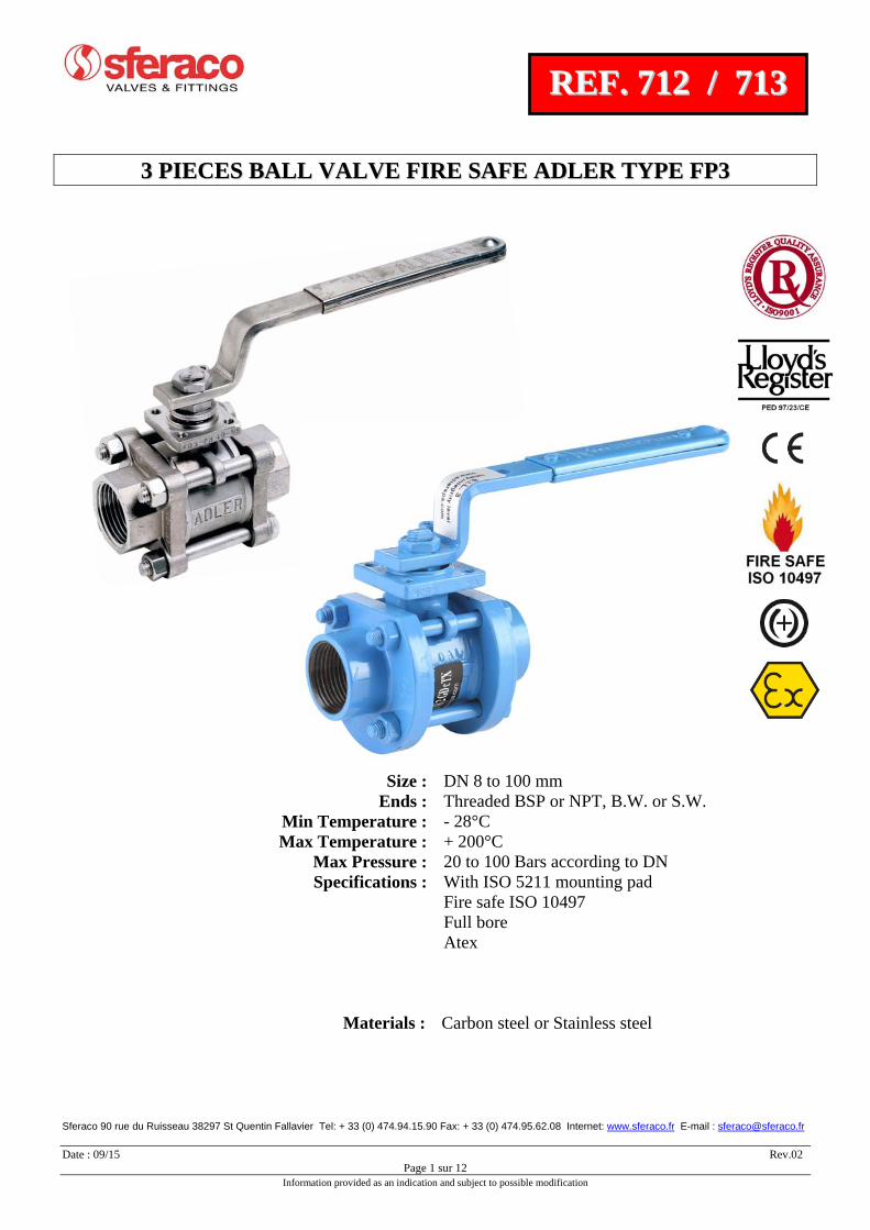
DN 8 to 100 mm Threaded BSP or NPT, B.W. or S.W. - 28°C + 200°C
Max Pressure : 20 to 100 Bars according to DNSpecifications : With ISO 5211 mounting pad
Fire safe ISO 10497
Full bore Atex
Materials : Carbon steel or Stainless steel
33 PPIIEECCEESS BBAALLLL VVAALLVVEE FFIIRREE SSAAFFEE AADDLLEERR TTYYPPEE FFPP33
Sferaco 90 rue du Ruisseau 38297 St Quentin Fallavier Tel: + 33 (0) 474.94.15.90 Fax: + 33 (0) 474.95.62.08 Internet: www.sferaco.fr E-mail : [email protected] Date : 09/15 Rev.02
Page 2 sur 12 Information provided as an indication and subject to possible modification
RREEFF.. 771122 // 771133
SPECIFICATIONS :
Full bore Anti blow-out stem With ISO 5211 mounting pad 3 pieces type Double antistatic device Fire safe ISO 10497 ( up to DN80 ), ISO-FT marking Fugitive emissions according to ISO 15848-1 : 2003 Class A 3 PTFE filled with 15% graphite chevrons rings on stem Packing with elastic rings Polyamid epoxy painting blue color RAL5012, 35 µ thickness for carbon steel types
USE :
Chemical and pharmaceutical industries, petrochemical industries, hydraulic installation, compressed air Min and max Temperature Ts : - 28°C to + 200°C Max pressure Ps :
DN 8 10 15 20 25 32 40 50 65 80 100
Ps ( Bars ) 100 100 64 64 40 40 40 40 25 25 20
Vacuum : 10
-5 torr Compressed air (ambient temperature) : 8 bars up to DN50, 6 bars from DN65 to 100 Steam : 6 bars up to DN50, 3 bars from DN65 to 100
RANGE :
Carbon steel body, threaded BSP ( NPT on request ), BW or SW Ref. 712 from DN 8 to DN 100
Stainless steel body, threaded BSP ( NPT on request ), BW or SW Ref. 713 from DN 8 to DN 100
Possible with IP67 gear box Ref. 9830260 à 262 from DN 15 to DN 100
ACCESSORIES AND OPTIONS :
Locking device Ref. 9830140 to 9830145 from DN 8 to DN 100 Stainless steel handle Ref. 9830170 to 9830175 from DN 8 to DN 100 Steel oval handle Ref. 9830270 to 9830272 from DN 8 to DN 32 Stainless steel oval handle Stainless steel bolting Carbon steel stem extension 100 mm Ref. 9830273 to 9830277 from DN 8 to DN 100 Stainless steel stem extension 100 mm Ref. 9830193 to 9830197 from DN 8 to DN 100 Deadman Ref. 9830160 to 9830165 from DN 15 to DN 50 Dry cleaned oxygen Ref. 9830150 to 9830155 from DN 8 to DN 100 Standard dry cleaned Seat PTFE filled with glass, graphite, stainless steel or metal Pocket less seat PTFE or PTFE filled with glass Specials coated Hole in the ball for overpressure device Double o ring on stem
ENDS :
Threaded female BSP Threaded female NPT ( on request ) Butt Welding ends Socket Welding ends
33 PPIIEECCEESS BBAALLLL VVAALLVVEE FFIIRREE SSAAFFEE AADDLLEERR TTYYPPEE FFPP33
Sferaco 90 rue du Ruisseau 38297 St Quentin Fallavier Tel: + 33 (0) 474.94.15.90 Fax: + 33 (0) 474.95.62.08 Internet: www.sferaco.fr E-mail : [email protected] Date : 09/15 Rev.02
Page 3 sur 12 Information provided as an indication and subject to possible modification
RREEFF.. 771122 // 771133
MATERIALS :
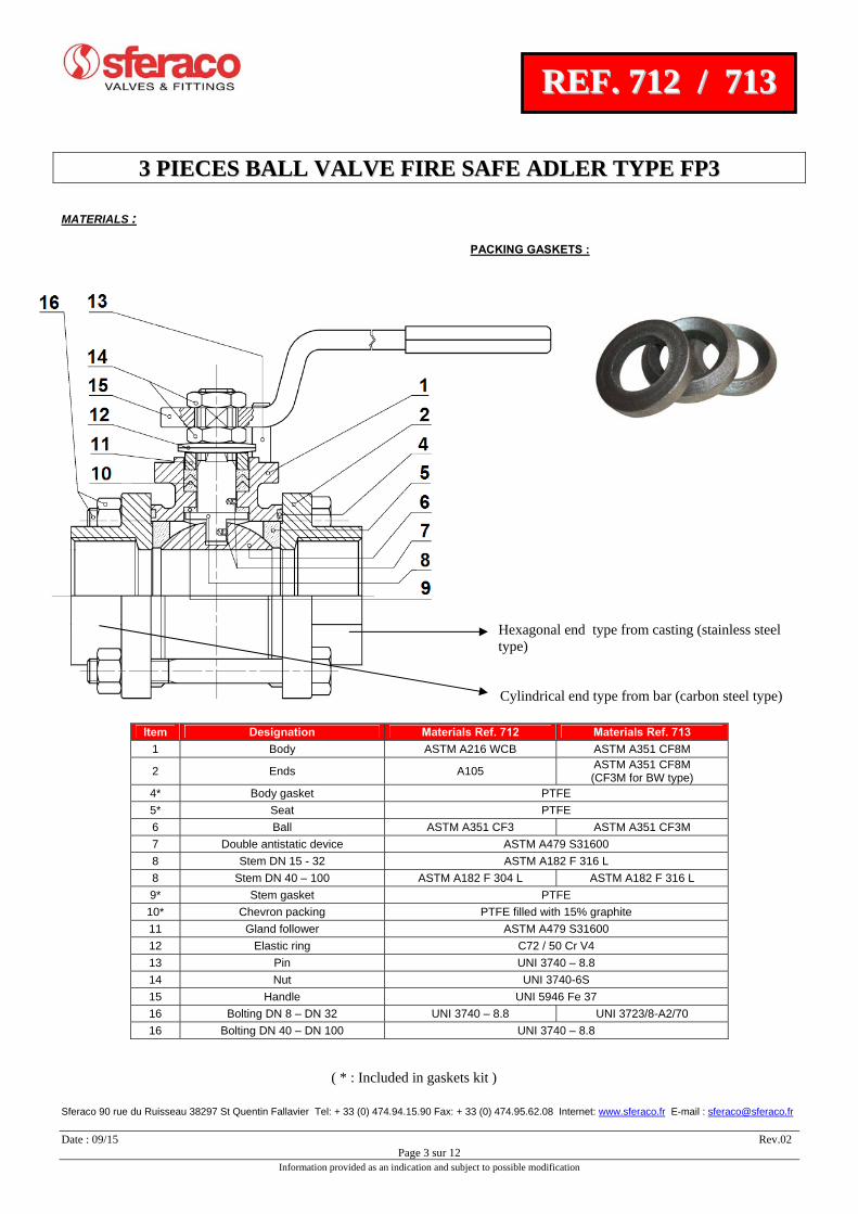
PACKING GASKETS :
Hexagonal end type from casting (stainless steel type)
Cylindrical end type from bar (carbon steel type)
( * : Included in gaskets kit )
Item Designation Materials Ref. 712 Materials Ref. 713
1 Body ASTM A216 WCB ASTM A351 CF8M
2 Ends A105 ASTM A351 CF8M (CF3M for BW type)
4* Body gasket PTFE
5* Seat PTFE
6 Ball ASTM A351 CF3 ASTM A351 CF3M
7 Double antistatic device ASTM A479 S31600
8 Stem DN 15 - 32 ASTM A182 F 316 L
8 Stem DN 40 – 100 ASTM A182 F 304 L ASTM A182 F 316 L
9* Stem gasket PTFE
10* Chevron packing PTFE filled with 15% graphite
11 Gland follower ASTM A479 S31600
12 Elastic ring C72 / 50 Cr V4
13 Pin UNI 3740 – 8.8
14 Nut UNI 3740-6S
15 Handle UNI 5946 Fe 37
16 Bolting DN 8 – DN 32 UNI 3740 – 8.8 UNI 3723/8-A2/70
16 Bolting DN 40 – DN 100 UNI 3740 – 8.8
33 PPIIEECCEESS BBAALLLL VVAALLVVEE FFIIRREE SSAAFFEE AADDLLEERR TTYYPPEE FFPP33
Sferaco 90 rue du Ruisseau 38297 St Quentin Fallavier Tel: + 33 (0) 474.94.15.90 Fax: + 33 (0) 474.95.62.08 Internet: www.sferaco.fr E-mail : [email protected] Date : 09/15 Rev.02
Page 4 sur 12 Information provided as an indication and subject to possible modification
RREEFF.. 771122 // 771133
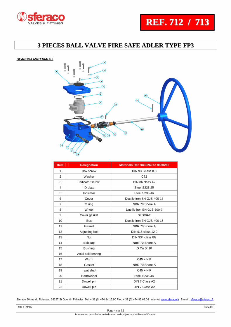
GEARBOX MATERIALS :
Item Designation Materials Ref. 9830260 to 9830265
1 Box screw DIN 933 class 8.8
2 Washer C72
3 Indicator screw DIN 86 class A2
4 ID plate Steel S235 JR
5 Indicator Steel S235 JR
6 Cover Ductile iron EN GJS-400-15
7 O ring NBR 70 Shore A
8 Wheel Ductile iron EN GJS-500-7
9 Cover gasket SL509AT
10 Box Ductile iron EN GJS-400-15
11 Gasket NBR 70 Shore A
12 Adjusting bolt DIN 915 class 12.9
13 Nut DIN 934 class 8G
14 Bolt cap NBR 70 Shore A
15 Bushing G Cu Sn10
16 Axial ball bearing -
17 Worm C45 + NiP
18 Gasket NBR 70 Shore A
19 Input shaft C45 + NiP
20 Handwheel Steel S235 JR
21 Dowell pin DIN 7 Class A2
22 Dowell pin DIN 7 Class A2
33 PPIIEECCEESS BBAALLLL VVAALLVVEE FFIIRREE SSAAFFEE AADDLLEERR TTYYPPEE FFPP33
Sferaco 90 rue du Ruisseau 38297 St Quentin Fallavier Tel: + 33 (0) 474.94.15.90 Fax: + 33 (0) 474.95.62.08 Internet: www.sferaco.fr E-mail : [email protected] Date : 09/15 Rev.02
Page 5 sur 12 Information provided as an indication and subject to possible modification
RREEFF.. 771122 // 771133
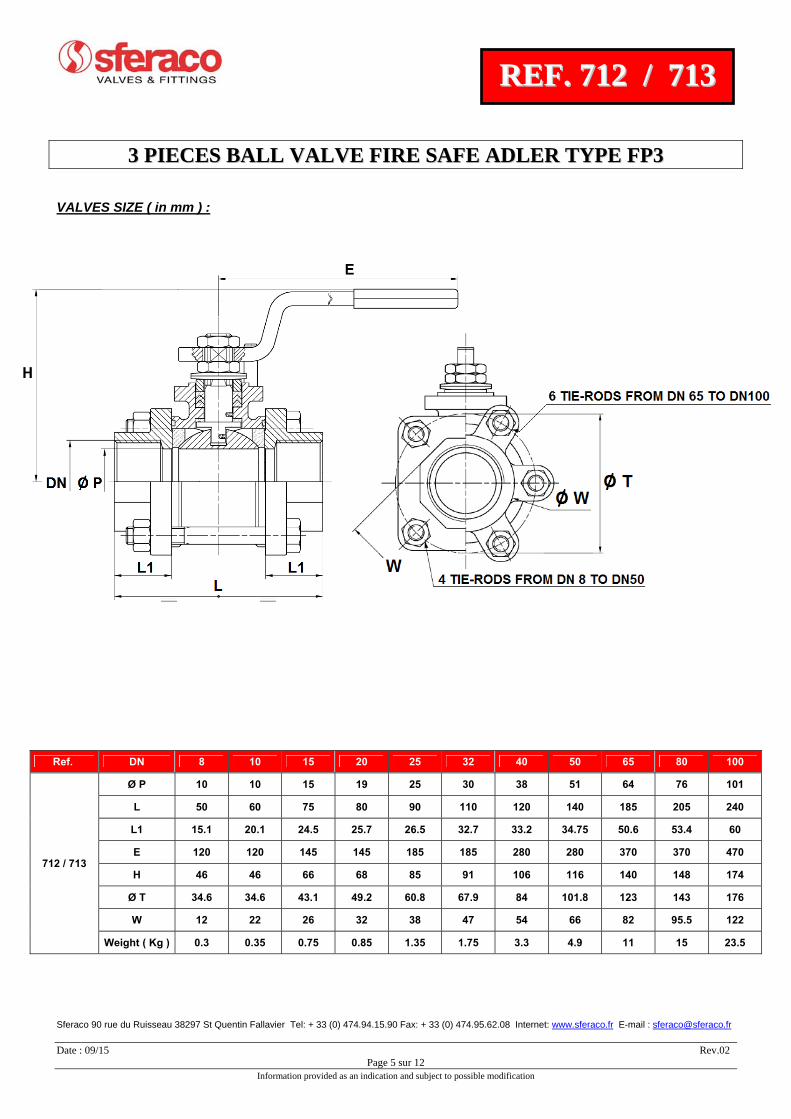
VALVES SIZE ( in mm ) :
Ref. DN 8 10 15 20 25 32 40 50 65 80 100
712 / 713
Ø P 10 10 15 19 25 30 38 51 64 76 101
L 50 60 75 80 90 110 120 140 185 205 240
L1 15.1 20.1 24.5 25.7 26.5 32.7 33.2 34.75 50.6 53.4 60
E 120 120 145 145 185 185 280 280 370 370 470
H 46 46 66 68 85 91 106 116 140 148 174
Ø T 34.6 34.6 43.1 49.2 60.8 67.9 84 101.8 123 143 176
W 12 22 26 32 38 47 54 66 82 95.5 122
Weight ( Kg ) 0.3 0.35 0.75 0.85 1.35 1.75 3.3 4.9 11 15 23.5
33 PPIIEECCEESS BBAALLLL VVAALLVVEE FFIIRREE SSAAFFEE AADDLLEERR TTYYPPEE FFPP33
Sferaco 90 rue du Ruisseau 38297 St Quentin Fallavier Tel: + 33 (0) 474.94.15.90 Fax: + 33 (0) 474.95.62.08 Internet: www.sferaco.fr E-mail : [email protected] Date : 09/15 Rev.02
Page 6 sur 12 Information provided as an indication and subject to possible modification
RREEFF.. 771122 // 771133
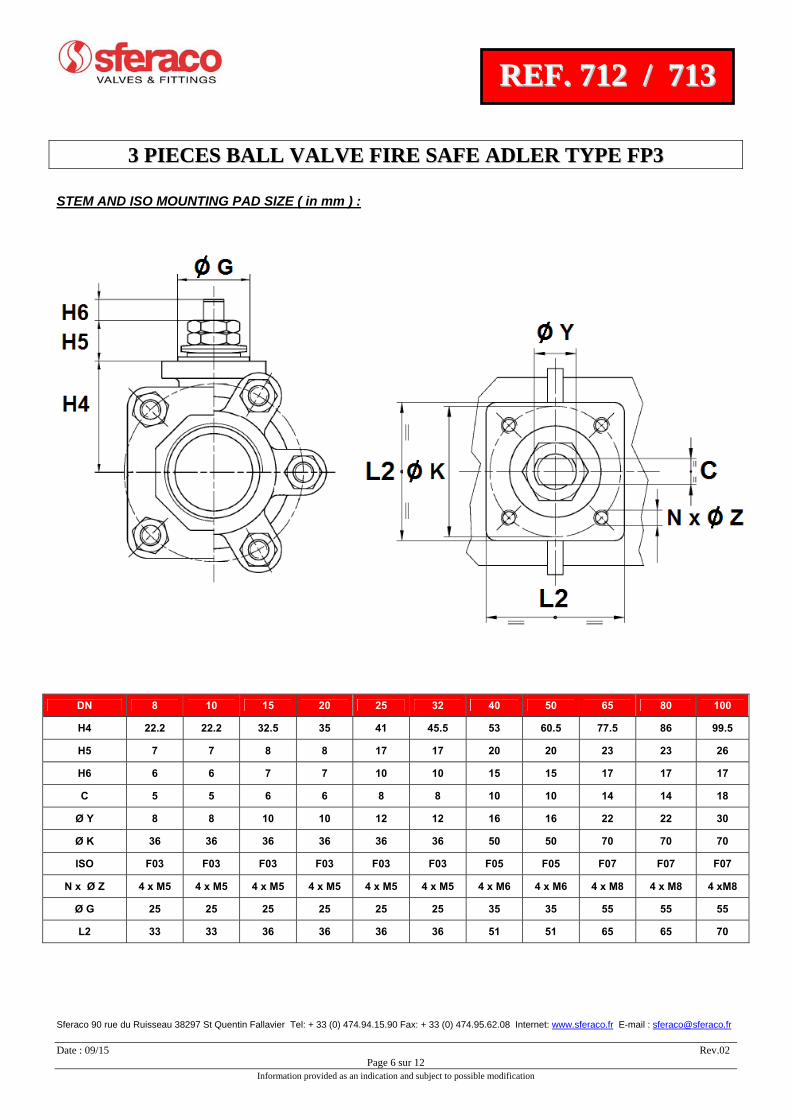
STEM AND ISO MOUNTING PAD SIZE ( in mm ) :
DN 8 10 15 20 25 32 40 50 65 80 100
H4 22.2 22.2 32.5 35 41 45.5 53 60.5 77.5 86 99.5
H5 7 7 8 8 17 17 20 20 23 23 26
H6 6 6 7 7 10 10 15 15 17 17 17
C 5 5 6 6 8 8 10 10 14 14 18
Ø Y 8 8 10 10 12 12 16 16 22 22 30
Ø K 36 36 36 36 36 36 50 50 70 70 70
ISO F03 F03 F03 F03 F03 F03 F05 F05 F07 F07 F07
N x Ø Z 4 x M5 4 x M5 4 x M5 4 x M5 4 x M5 4 x M5 4 x M6 4 x M6 4 x M8 4 x M8 4 xM8
Ø G 25 25 25 25 25 25 35 35 55 55 55
L2 33 33 36 36 36 36 51 51 65 65 70
33 PPIIEECCEESS BBAALLLL VVAALLVVEE FFIIRREE SSAAFFEE AADDLLEERR TTYYPPEE FFPP33
Sferaco 90 rue du Ruisseau 38297 St Quentin Fallavier Tel: + 33 (0) 474.94.15.90 Fax: + 33 (0) 474.95.62.08 Internet: www.sferaco.fr E-mail : [email protected] Date : 09/15 Rev.02
Page 7 sur 12 Information provided as an indication and subject to possible modification
RREEFF.. 771122 // 771133
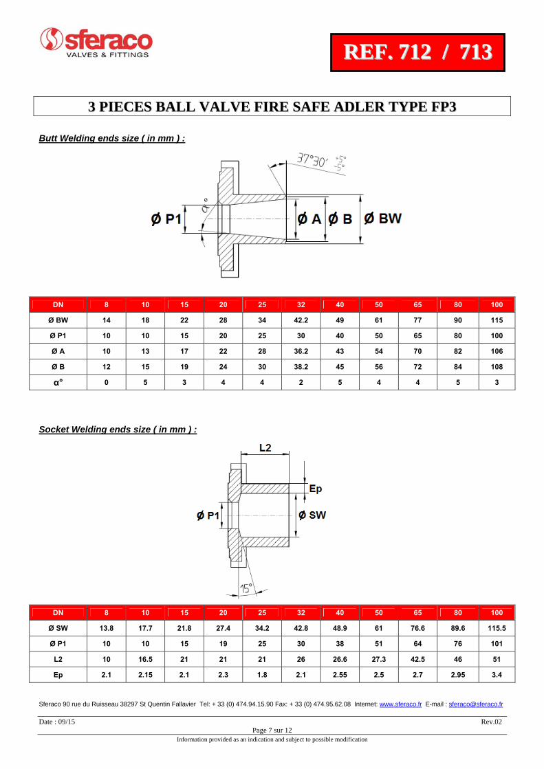
Butt Welding ends size ( in mm ) :
Socket Welding ends size ( in mm ) :
DN 8 10 15 20 25 32 40 50 65 80 100
Ø BW 14 18 22 28 34 42.2 49 61 77 90 115
Ø P1 10 10 15 20 25 30 40 50 65 80 100
Ø A 10 13 17 22 28 36.2 43 54 70 82 106
Ø B 12 15 19 24 30 38.2 45 56 72 84 108
α° 0 5 3 4 4 2 5 4 4 5 3
DN 8 10 15 20 25 32 40 50 65 80 100
Ø SW 13.8 17.7 21.8 27.4 34.2 42.8 48.9 61 76.6 89.6 115.5
Ø P1 10 10 15 19 25 30 38 51 64 76 101
L2 10 16.5 21 21 21 26 26.6 27.3 42.5 46 51
Ep 2.1 2.15 2.1 2.3 1.8 2.1 2.55 2.5 2.7 2.95 3.4
33 PPIIEECCEESS BBAALLLL VVAALLVVEE FFIIRREE SSAAFFEE AADDLLEERR TTYYPPEE FFPP33
Sferaco 90 rue du Ruisseau 38297 St Quentin Fallavier Tel: + 33 (0) 474.94.15.90 Fax: + 33 (0) 474.95.62.08 Internet: www.sferaco.fr E-mail : [email protected] Date : 09/15 Rev.02
Page 8 sur 12 Information provided as an indication and subject to possible modification
RREEFF.. 771122 // 771133
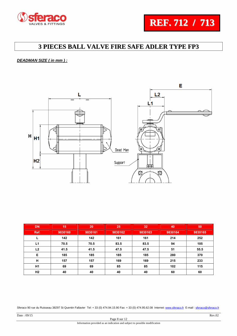
DEADMAN SIZE ( in mm ) :
DN 15 20 25 32 40 50
Ref. 9830160 9830161 9830162 9830163 9830164 9830165
L 142 142 161 161 214 252
L1 70.5 70.5 83.5 83.5 94 105
L2 41.5 41.5 47.5 47.5 51 55.5
E 185 185 185 185 280 370
H 157 157 169 169 215 233
H1 69 69 85 85 102 115
H2 40 40 40 40 60 60

33 PPIIEECCEESS BBAALLLL VVAALLVVEE FFIIRREE SSAAFFEE AADDLLEERR TTYYPPEE FFPP33
Sferaco 90 rue du Ruisseau 38297 St Quentin Fallavier Tel: + 33 (0) 474.94.15.90 Fax: + 33 (0) 474.95.62.08 Internet: www.sferaco.fr E-mail : [email protected] Date : 09/15 Rev.02
Page 9 sur 12 Information provided as an indication and subject to possible modification
RREEFF.. 771122 // 771133
GEARBOX SIZE ( in mm ) :
DN 15-50 65-80 100
C1 22 22 22
H1 57 57 100
H2 46 46 55
H3 98 98 143
H4 50.5 50.5 79.5
H5 56 56 73
H6 106 146 205
H7 34 34 35
H8 60 60 80
H9 117 131 250
Ø R 98 98 143
Ø V 120 200 300
Weight ( Kg ) 2.2 2.3 4.5
Ref. 9830260 9830261 9830262

33 PPIIEECCEESS BBAALLLL VVAALLVVEE FFIIRREE SSAAFFEE AADDLLEERR TTYYPPEE FFPP33
Sferaco 90 rue du Ruisseau 38297 St Quentin Fallavier Tel: + 33 (0) 474.94.15.90 Fax: + 33 (0) 474.95.62.08 Internet: www.sferaco.fr E-mail : [email protected] Date : 09/15 Rev.02
Page 10 sur 12 Information provided as an indication and subject to possible modification
RREEFF.. 771122 // 771133
GEARBOX SPECIFICATIONS :
TORQUE VALUES ( in Nm without safety coefficient ) :
DN 8 10 15 20 25 32 40 50 65 80 100
Torque ( Nm ) PN100 6 6 - - - - - - - - -
Torque ( Nm ) PN64 - - 7 13.4 - - - - - - -
Torque ( Nm ) PN40 - - - - 14.5 18 33 44 - - -
Torque ( Nm ) PN25 - - - - - - - - 69 84 -
Torque ( Nm ) PN20 - - - - - - - - - - 144
We recommend a safety coefficient of 2 to choose the actuator
DN 15-50 65-80 100-150
Ref. 9830260 9830261 9830262
Ratio factor 40 :1 40 :1 37 :1
Input torque ( Nm ) 35 34 43
Output torque ( Nm ) 100 150 500
33 PPIIEECCEESS BBAALLLL VVAALLVVEE FFIIRREE SSAAFFEE AADDLLEERR TTYYPPEE FFPP33
Sferaco 90 rue du Ruisseau 38297 St Quentin Fallavier Tel: + 33 (0) 474.94.15.90 Fax: + 33 (0) 474.95.62.08 Internet: www.sferaco.fr E-mail : [email protected] Date : 09/15 Rev.02
Page 11 sur 12 Information provided as an indication and subject to possible modification
RREEFF.. 771122 // 771133
STANDARDS :
Fabrication according to ISO 9001:2008 DIRECTIVE 97/23/CE : CE N° 0038
Risk category III module H
Designing according to BS EN 12516-2
Construction according to ISO 14313
Materials according to NACE MR 01-75
Pressure tests according to EN 12266-1, range A
Marking according to EN 19
Fire safe according to ISO 10497 up to DN80
Fugitive emissions according to ISO 15848-1 : 2003 Range A
SIL3 according to IEC/EN 61508 ( on request )
Threaded BSP cylindrical ends according to ISO 7-1 Rp
Threaded NPT ends according to ANSI B1.20.1 ( on request )
Butt Welding ends according to UNI EN 12627 ( EX DIN 3239 )
ISO 5211 mounting pad
Length according to DIN 3202 M3
ATEX Group II Category 2 GDc TX Zone 1 & 21 Zone 2 & ( optional marking )
On request ATEX Group II Category 1G/Dc TX Zone 0 & 20 ADVICE : Our opinion and our advice are not guaranteed and SFERACO shall not be liable for the consequences of damages. The customer must check the right choice of the products with the real service conditions.
33 PPIIEECCEESS BBAALLLL VVAALLVVEE FFIIRREE SSAAFFEE AADDLLEERR TTYYPPEE FFPP33
Sferaco 90 rue du Ruisseau 38297 St Quentin Fallavier Tel: + 33 (0) 474.94.15.90 Fax: + 33 (0) 474.95.62.08 Internet: www.sferaco.fr E-mail : [email protected] Date : 09/15 Rev.02
Page 12 sur 12 Information provided as an indication and subject to possible modification
RREEFF.. 771122 // 771133
INSTALLATION AND MAINTENANCE BEFORE INSTALLATION : Pipe-line must be cleaned and free from residual of weldings,rubbish,shaving and every kind of extraneous materials. Pipe-line must be perfectly aligned and their support properly dimensioned so that there’s no external constraint. Check to use a produce compatible to the services conditions for the sealing of the threaded types. To tighten the ends,use the appropriate tool. Use the right bolt tightening so that the ends won’t be damaged. The welding of the ends for the SW and the BW types,must be done with the central part removed. A gauge can be used to have the good lenght and alignement between the ends. INSTALLATION OF THE CENTRAL PART During the installation of the central part , tighten bolts according to the table below.Tighten bolts in cross. CLEANING AND TESTS Keep closed the valves during the cleaning operation so that there’s no impurities between the ball and the body. Tests under pressure must be done with a cleaned pipe-line. Open partially the valve for tests. Pressure test do not exceed the valve specifications according to EN 12266-1. MAITENANCE It’s recommended to operate the valve twice ( open and close ) 1 to 2 times per year. When intervention on the valve, be sure there’s no pressure in the pipe-line, there’s no fluid in it,and that it is isolated. The temperature must be low enough to operate without risks. If there’s a corrosive fluid,inert installation before intervention. When the valve is under pressure : If there’s a leakage between the body and the ends, tighten bolts according to the above table If there’s a leakage at the packing, tighten it slightly so that the leakage disappears. MAINTENANCE OPERATION IN WORKSHOP REPLACEMENT OF SEAT GASKETS AND PACKING. The central part must be removed. Turn the ball at 45° and removed the seat gaskets. Operate the valve in closed position to remove the ball. Verify the surface of the ball has no impacts and no scores. If there are important scores or impatcs,replace the ball. Clean inside the body valve and remove the impurities. To replace the packing,remove the handle,unscrew the gland nut, extract the stem by the inside of the valve. Clean the paking seat. Reassemble thrust washer on stem, introduce stem by the inside of the valve, reassemble packing with packing nut,reassemble hand washer,hand nut and the handle. Turn stem in closed position and insert the ball. Then turn the ball in opened position and reassemble the seat. Place the valve on the installation,tighten bolts according to the above table. Then proceed to the tests in the same way that the first installation.