reel lawnmower - university of louisville report.pdfreel lawnmowers have been around for centuries....
TRANSCRIPT

UNIVERSITY OF LOUISVILLE
Reel Lawnmower Me 380 Design Project
Nathan Fletcher
3/15/2007
Reel lawnmowers have been around for centuries. Today they are used for grass cutting in high‐end applications, such as athletic fields and golf courses. In this design project, a modern reel lawnmower will be analyzed and partially redesigned for improved performance.

Problem Definition
Background: Reel lawnmowers were invented in the 19th century, and allowed for easy, consistent grass cutting. Today, reel lawn mowers are used commercially for grounds keeping in such applications as golf courses, sports fields, and other venues where short, consistent grass is desirable. Reel lawn mowers are also available for consumer use as an alternative to gas and electric powered mowers. Need: The reel lawn mower that I own has a couple of problems. First, it gets "clogged" by thick areas of grass, causing the mower to stop instantly, throwing the pusher into the handle bars. I am going to modify the design of this mower in order to reduce that problem. Goal: The goal of this project is to increase the efficiency of the reel lawnmower being analyzed. Specifically, the wheel radius will be increased to allow the blades to spin faster, increasing the force with which they cut the grass, and reducing the chances of the mower becoming clogged. Objectives:
• Accurately model the components of the reel lawnmower in Solid Edge
• Modify the parts in Solid Edge to achieve more desirable performance
• Create an assembly and animation of the lawnmower, with parts moving accurately
• Analyze the original and redesigned parts in Solid Edge Design Requirements: The first priority of this project is to achieve the goal of increasing the lawnmower's efficiency by increasing its blade speed. The modifications made to this mower will be done with a negligible increase in stress in the components. Constraints: The redesigned parts must be as easily manufactured as the original parts. No exotic materials will be used for strength increases or weight reductions.
Synthesis
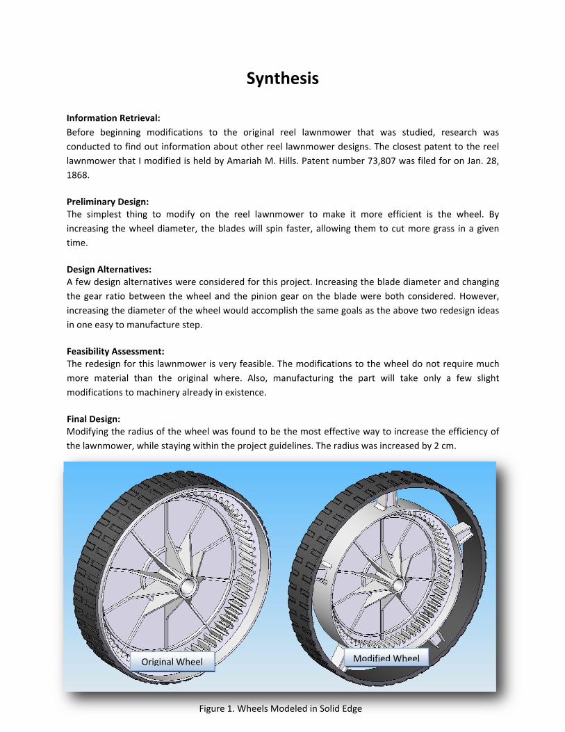
Information Retrieval: Before beginning modifications to the original reel lawnmower that was studied, research was conducted to find out information about other reel lawnmower designs. The closest patent to the reel lawnmower that I modified is held by Amariah M. Hills. Patent number 73,807 was filed for on Jan. 28, 1868. Preliminary Design: The simplest thing to modify on the reel lawnmower to make it more efficient is the wheel. By increasing the wheel diameter, the blades will spin faster, allowing them to cut more grass in a given time. Design Alternatives: A few design alternatives were considered for this project. Increasing the blade diameter and changing the gear ratio between the wheel and the pinion gear on the blade were both considered. However, increasing the diameter of the wheel would accomplish the same goals as the above two redesign ideas in one easy to manufacture step. Feasibility Assessment: The redesign for this lawnmower is very feasible. The modifications to the wheel do not require much more material than the original where. Also, manufacturing the part will take only a few slight modifications to machinery already in existence. Final Design: Modifying the radius of the wheel was found to be the most effective way to increase the efficiency of the lawnmower, while staying within the project guidelines. The radius was increased by 2 cm.
Modified Wheel Original Wheel
Figure 1. Wheels Modeled in Solid Edge
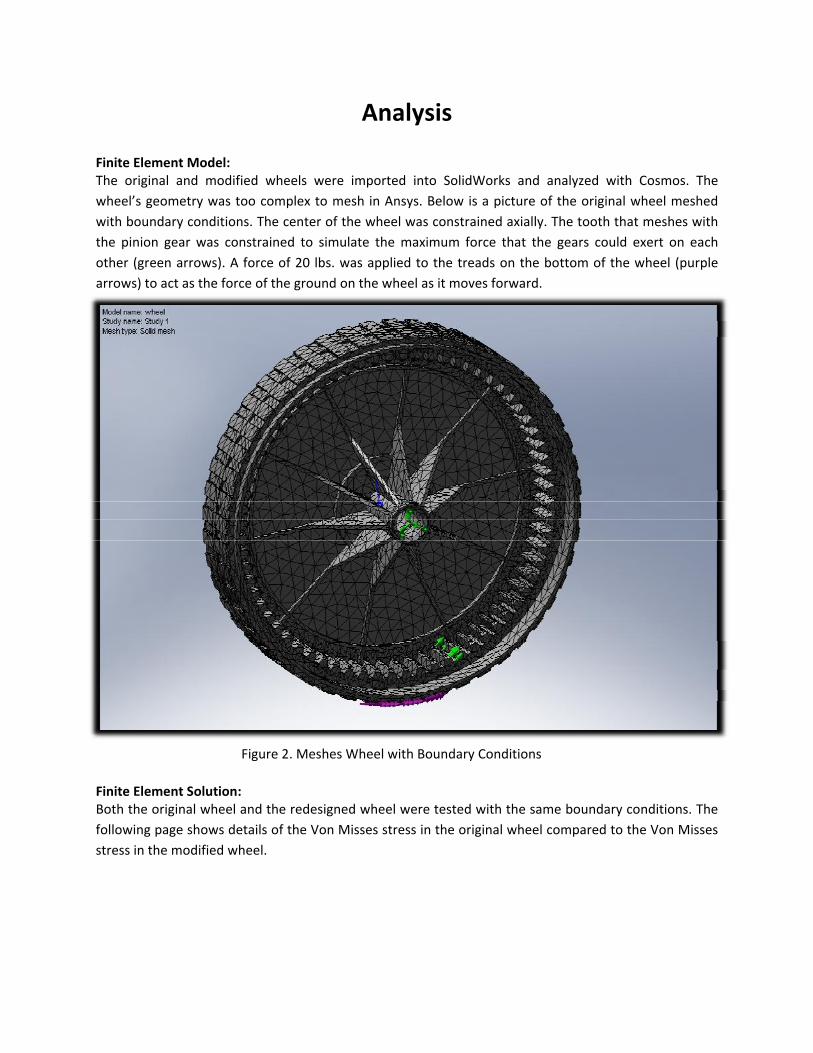
Analysis Finite Element Model: The original and modified wheels were imported into SolidWorks and analyzed with Cosmos. The wheel’s geometry was too complex to mesh in Ansys. Below is a picture of the original wheel meshed with boundary conditions. The center of the wheel was constrained axially. The tooth that meshes with the pinion gear was constrained to simulate the maximum force that the gears could exert on each other (green arrows). A force of 20 lbs. was applied to the treads on the bottom of the wheel (purple arrows) to act as the force of the ground on the wheel as it moves forward.
Figure 2. Meshes Wheel with Boundary Conditions Finite Element Solution: Both the original wheel and the redesigned wheel were tested with the same boundary conditions. The following page shows details of the Von Misses stress in the original wheel compared to the Von Misses stress in the modified wheel.
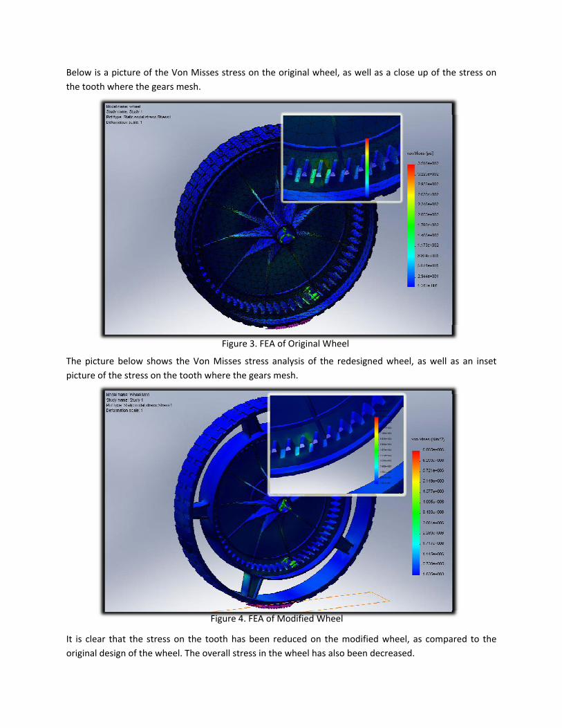
Below is a picture of the Von Misses stress on the original wheel, as well as a close up of the stress on the tooth where the gears mesh.
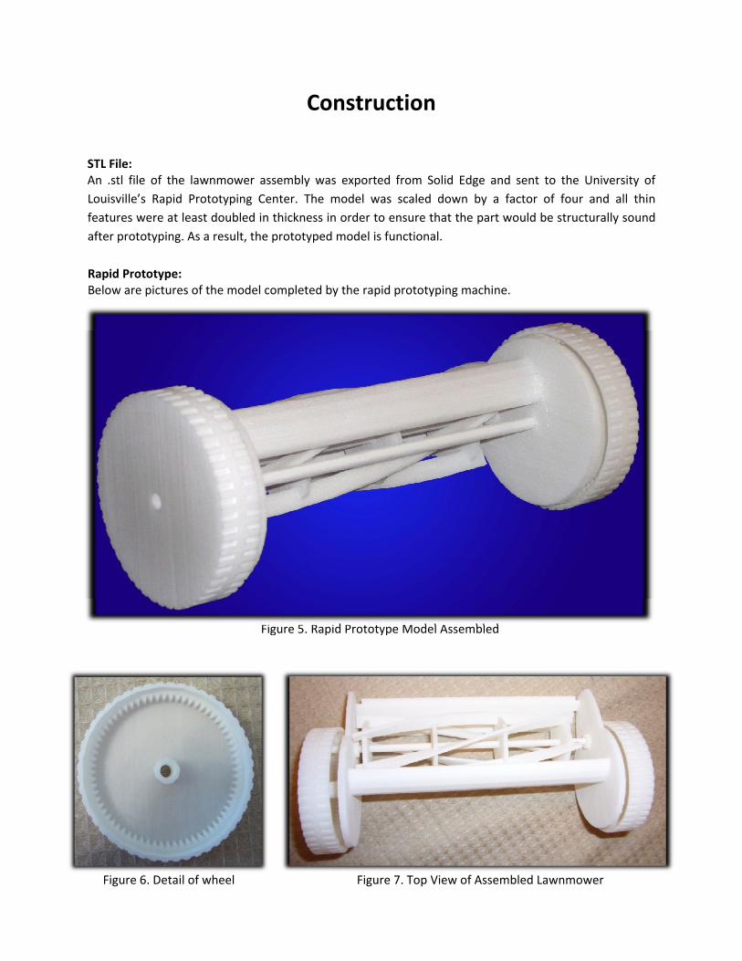
Figure 3. FEA of Original Wheel The picture below shows the Von Misses stress analysis of the redesigned wheel, as well as an inset picture of the stress on the tooth where the gears mesh.
Figure 4. FEA of Modified Wheel It is clear that the stress on the tooth has been reduced on the modified wheel, as compared to the original design of the wheel. The overall stress in the wheel has also been decreased.
Construction
STL File: An .stl file of the lawnmower assembly was expo from Solid Edge and sent to the University of
’s Rapid Prototyping Center. The model was scaled down by a factor of four and all thin
elow are pictures of the model completed by the rapid prototyping machine.
Fi
rtedLouisvillefeatures were at least doubled in thickness in order to ensure that the part would be structurally sound after prototyping. As a result, the prototyped model is functional. Rapid Prototype: B
gure 5. Rapid Prototype Model Assembled
Figure 6. Detail of wheel Figure 7. Top View of Assembled Lawnmower
Testing
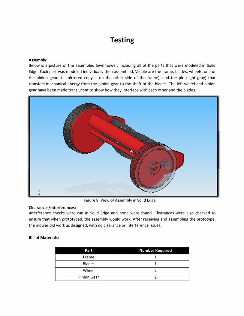
Assembly: Below is a picture of the assembled lawnmower, including all of the parts that were modeled in Solid Edge. Each part was modeled individually then assembled. Visible are the frame, blades, wheels, one of the pinion gears (a mirrored copy is on the other side of the frame), and the pin (light gray) that transfers mechanical energy from the pinion gear to the shaft of the blades. The left wheel and pinion gear have been made translucent to show how they interface with each other and the blades.
Clearances/Interferences: Interference checks were run in Solid Edge and none were found. Clearances were also checked to ensure that when prototyped, the assembly would work. After receiving and assembling the prototype, the mower did work as designed, with no clearance or interference issues. Bill of Materials:
Part Number Required
Frame 1
Blades 1
Wheel 2
Pinion Gear 2
Figure 8. View of Assembly in Solid Edge

Pin 2

Evaluation
Results: This project was completed exactly as intended and exceeded the initial goals. Not only is the redesign more efficient than the original, the modified wheel has less stress in the wheel and the teeth. Conclusions: As is apparent from the finite element analysis of the wheel, the modifications were successful in accomplishing the goals that were initially set. Increasing the Wheel diameter with the pictured spoke design reduced the stress on the plastic, while increasing the blade rotation speed, making the mower more efficient. Recommendations: Modifying the entire frame may help with the implementation of the larger wheel, which may provide for slightly less ergonomic operation as is. I would also recommend using a higher grade steel for the cutting surfaces, as they have rusted after about a year of use.