reduction of acceleration induced injuries from mine ...atabiei/pdfs/j.pdf · reduction of...
TRANSCRIPT

Reduction of Acceleration Induced Injuries from Mine Blasts under Infantry Vehicles
Ala Tabiei1 and Gaurav Nilakantan2
Dept. Of Aerospace Engineering and Engineering Mechanics
University of Cincinnati, OH 45221, USA
Abstract Anti tank (AT) mines and improvised explosive devices (IED) pose a serious
threat to the occupants of infantry vehicles. The use of an energy absorbing seat
in conjunction with vehicle armor plating greatly improves occupant survivability
during such an explosion. The dynamic axial crushing of aluminum tubes
constitutes the principal energy absorption mechanism to reduce the blast pulse
transmitted to the occupant in this investigation. The explicit non-linear finite
element software LSDYNA is used to simulate the effect of an explosion under a
vehicle seat in which an occupant is seated. The injury mechanisms of the
vehicle-occupant contact interface corresponding to the vehicle seat structure
upon the occupant’s torso are simulated. Data such as compressive lumbar
loads, head and torso accelerations, and neck moments are collected from the
numerical dummy which is used to simulate the occupant’s response. This data
is then compared to injury threshold values from various references to assess
survivability.
Keywords: Energy Absorbing Seat, Mine Blast, LSDYNA, Occupant Protection,
Survivability, Energy Balance Formulation, Axial Crushing
1 Professor, Corresponding Author. Tel.: +1 513 556 3367, Email address:
2 Graduate Student
1
1. Introduction
During the explosion of an AT (anti tank) mine or IED (improvised explosive
device) under an infantry vehicle, significant impulse loads are transmitted to the
occupant through the vehicle-occupant interfaces such as the floor and seat. If
these loads are not attenuated to survivable levels, it normally leads to fatality of
the occupant. Armor plating a vehicle is not sufficient to protect the occupant
against land mine explosions and thus further protective techniques need to be
investigated.
One such concept is an Energy Absorbing Seat Mechanism (EASM) that
cushions the occupant against these shock pulses by absorbing the kinetic
energy of a mine blast through the elastic and/or plastic deformation of various
energy absorbing elements thereby attenuating acceleration pulses transmitted
from the vehicle structure to the occupant to survivable levels. There is currently
no effective energy absorbing seat mechanism in use in US Army ground combat
vehicles.
In 1996, Alem et al. [1] evaluated an energy absorbing truck seat to evaluate its
effectiveness in protection against landmine blasts. In 1998, the Night Vision and
Electronic Sensors Directorate published a report on Tactical Wheeled Vehicles
and Crew Survivability in Landmine Explosions [2]. Concepts that are used in the
crashworthiness analysis of aircraft seats are some what similar to those used in
crew protection against mine blasts. This is because both events predominantly
deal with the attenuation of very large vertical acceleration pulses. In 2002,
Kellas [3] designed an energy absorbing seat for an agricultural aircraft using the
axial crushing of aluminum tubes as the primary energy absorber, which forms
the basis of our simulation.
This study focuses on the numerical simulation of an EASM subjected to a mine
blast. The mine blast is realistically simulated by prescribing acceleration pulses
to the structure that imparts the same response to the structure as would an
actual land mine explosion directly underneath an infantry vehicle. The human
occupant is simulated by a numerical 5th percentile HYBRID III dummy. Data
2

such as head and torso acceleration, neck moments, and dummy-structure
contact forces are collected during the simulation and analyzed for injury
assessment. Only the contact interface of the occupant and seat is focused upon
in the first part. New concepts to further minimize transmitted pulses are
introduced, such as a foam and airbag cushion. The EASM design is then
finalized.
In order to determine the effectiveness of a design that protects occupants
against injury caused by crash and mine blasts, certain injury criteria need to be
defined. Occupant crash data such as forces, moments and accelerations are
collected from experiments or simulations and then compared to these injury
criteria to assess occupant survivability and human injury. It is important to note
that these injury criteria cannot predict the extent of an injury; rather they indicate
whether the injury will occur and if so, the probability of survival. According to [4],
the approximate tolerance level for -Gz accelerative force is 15 G, while for +Gz it
is 25 G. The lumber load criteria states that the maximum compressive load shall
not exceed 1500 pounds (6672 N) measured between the pelvis and lumbar
spine of a 50th-percentile test dummy for a crash pulse in which the predominant
impact vector is parallel to the vertical axis of the spinal column. Also, the
compressive load must not exceed 3800 N in a 30 ms interval. This is one of the
most widely used criterions in vertical crash and impact testing [3-8]. If the spinal
cord is severely compressed or severed, it can lead to either instant paralysis or
fatality.
The U.S. Army’s Aberdeen Test Center [4] has established injury criteria for mine
blast testing of high mobility multipurpose wheeled vehicles (HMMWV). These
criteria are comprehensive, provide a good assessment of injury, and take into
account the entire occupant’s body subject to any combination of external stimuli
associated with a mine blast. A few criteria are listed in Table 1.
3
2. Review of Human Injury Tolerance Criteria
In order to determine the effectiveness of a design that protects occupants
against injury caused by crash and mine blasts, certain injury criteria need to be
defined. Occupant crash data such as forces, moments and accelerations are
collected from simulations and then compared to these injury criteria to assess
Occupant Survivability and Human Injury. Summary of the injury criteria available
in the literature are listed in the following section.
2.1 Generalized Human Tolerance Limits to Acceleration Table 1 [4] displays the human tolerance limits for typical crash pulses along
three mutually orthogonal axes, for a well restrained young male. These values
provide a general outline of the safe acceleration limit for a human during a
typical crash. However, the time duration of the applied acceleration pulse has
not been specified. Higher acceleration pulses can be sustained for shorter
durations compare to lower acceleration pulses for longer durations, thus the
time duration in question is important [4].
2.2 Injury Scaling Injury scaling is a technique for assigning a numerical assessment or severity
score to traumatic injuries in order to quantify the severity of a particular injury.
The most extensively used injury scale is the Abbreviated Injury Scale (AIS)
developed by the American Association for Automotive Medicine and originally
published in 1971. The AIS assigns an injury severity of “one” to “six” to each
injury according to the severity of each separate anatomical injury. The primary
limitation of the AIS is that it looks at each injury in isolation and does not provide
an indication of outcome for the individual as a whole. Consequently, the Injury
Severity Score (ISS) was developed in 1974 to predict probability of survival. The
ISS is a numerical scale that is derived by summing the squares of the three
highest body region AIS values. This gives a score ranging from 1 to 75. The
4

maximal value of 75 results from three AIS 5 injuries, or one or more AIS 6
injuries. Probabilities of death have been assigned to each possible score.
2.3 Dynamic Response Index (DRI) The DRI is representative of the maximum dynamic compression of the vertebral
column and is calculated by describing the human body in terms of an
analogous, lumped-mass parameter, mechanical model consisting of a mass,
spring and damper. The DRI model assesses the response of the human body to
transient acceleration-time profiles. DRI has been effective in predicting spinal
injury potential for + Gz acceleration environments in ejection seats. DRI is
acceptable for evaluation of crash resistant seat performance relative to spinal
injury, if used in conjunction with other injury criteria including Eiband and
Lumbar Load thresholds [4].
2.4 Lumbar Load Criterion The maximum compressive load shall not exceed 1500 pounds (6672 N)
measured between the pelvis and lumbar spine of a 50th-percentile test dummy
for a crash pulse in which the predominant impact vector is parallel to the vertical
axis of the spinal column. Also, the compressive load must not exceed 3800 N in
a 30 ms interval. This is one of the most widely used criterions in vertical crash
and impact testing. If the spinal cord is severely compressed or severed, it can
lead to either instant paralysis or fatality. [1, 5-8]
2.5 Head Injury Criterion (HIC) HIC was proposed by the National Highway Traffic Safety Administration
(NHTSA) in 1972 and is an alternative interpretation to the Wayne State
Tolerance Curve (WSTC) [4, 7]. It is used to assess forehead impact against
unyielding surfaces. Basically, the acceleration-time response is experimentally
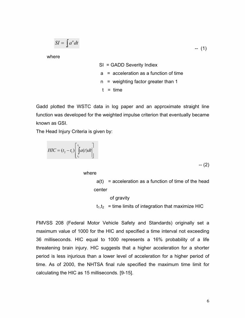
measured and the data is related to skull fractures. Gadd [9] had suggested a
weighted-impulse criterion (GADD Severity Index, GSI) as an evaluator of injury
potential defined as:
5
where
SI = GADD Severity Indiex
on of time
add plotted the WSTC data in log paper and an approximate straight line
Criteria is given by:
-- (2)
(t) acce ration as a function of time of the head
f gravity
of integration that maximize HIC
MVSS 208 (Federal Motor Vehicle Safety and Standards) originally set a
-- (1) n
tSI a dt= ∫
a = acceleration as a functi
n = weighting factor greater than 1
t = time
G
function was developed for the weighted impulse criterion that eventually became
known as GSI.
The Head Injury
2.5
2
2 1( ) ( )t
HIC t t a t dt= − ∫1t
where
a = le
center
o
t1,t2 = time limits
F
maximum value of 1000 for the HIC and specified a time interval not exceeding
36 milliseconds. HIC equal to 1000 represents a 16% probability of a life
threatening brain injury. HIC suggests that a higher acceleration for a shorter
period is less injurious than a lower level of acceleration for a higher period of
time. As of 2000, the NHTSA final rule specified the maximum time limit for
calculating the HIC as 15 milliseconds. [9-15].
6

2.6 Head Impact Power (HIP) posal of a new HIC entitled Head Impact Power
.7 Injury Assessment Reference Values (IARS) ations, instrumentation, test
.8 Neck Injury Criterion (NIC) eration between the C1 and T1 vertebra and is
-- (3)
-- (4)
IC must not exceed 15 m2/s2 [17]. Another criteria NIC50 refers to NIC at 50mm
A recent report included the pro
(HIP) It considers not only kinematics of the head (rigid body motion of the skull)
but also the change in kinetic energy of the skull which may result in deformation
of and injury to the non-rigid brain matter. The Head Impact Power (HIP) is based
on the general rate of change of the translational and rotational kinetic energy.
The HIP is an extension of previously suggested “Viscous Criterion” first
proposed by Lau and Viano in 1986, which states that a certain level or
probability of injury will occur to a viscous organ if the product of its compression
‘C’ and the rate of compression ‘V’ exceeds some limiting value [4].
2This rule adopts new requirements for specific
procedures and calibration for the Hybrid III test dummy [4]. The regulation’s
preamble has a detailed discussion of the injury mechanisms and the relevant
automotive mishap data for each of the injury criteria associated with the Hybrid
III ATD. Military test plans should implement these criteria.
2The NIC considers relative accel
given by [16]:
2( ) 0.2 ( ) [ ( )]rel relNIC t xa t V t= +
where
v t 1( ) ( ) ( )T Headrel x xa t a t= −∫ ∫
1( ) ( ) ( )T Headrel x xa t a t a t= −
N
of C1-T1 (cervical-thoracic) retraction. Newly proposed Nij criteria by NHTSA
combines effects of forces and moments measured at occipital condyles and is a
7

better predictor of cranio-cervical injuries. Nij takes into account NTE (tension-
extension), NTF (tension-flexion), NCE (compression-extension), NCF
(compression-flexion). FMVSS specification No.208 requires that none of the four
Nij values exceed 1.4 at any point. The generalized NIC is given by [18]:
-- (5)
Fz = Upper Neck Axial Force (N),
yle
FMVSS 208 (2000) final rule a neck injury criterion, designated Nij, is used.
.9 Chest Criteria leration will not exceed 60 G’s for more than 3 milliseconds
.10 Viscous Criterion defined as the chest compression velocity (derived by
ijZC YF M
where
My = Moment about Occipital Cond
Fzn = Axial Force Critical Value (N), and
Myn = Moment Critical Value (N-m).
In
This criterion is based on the belief that the occipital condoyle-head junction can
be approximated by a prismatic bar and that the failure for the neck is related to
the stress in the ligament tissue spanning the area between the neck and the
head. Nij must not exceed 1.0 [14, 15, 16, 18].
2Peak resultant acce
(Mertz, 1971) as measured by a Tri-axial accelerometer in upper thorax. Also,
the chest compression will be less than 3 inches for the Hybrid III dummy as
measured by a chest potentiometer behind the sternum [4, 7].
2Viscous Criterion (V*C) –
differentiating the measured chest compression) multiplied by the chest
compression and divided by the chest depth. This criterion has been mentioned
for the sake of completeness of information; however it is not widely used [4].
Z Y
C
F M = +
N
8

2.11 Femur Force Criterion ompressive force transmitted axially through each
rete spring elements of known stiffness are included
.12 Thoracic Trauma Index (TTI) by:
-- (6)
R is the greater of the peak accelerations of either the upper or lower rib,
This criterion states that the c
upper leg should not exceed a certain value. Impulse loads that exceed this limit
can cause complete fracture of the femoral bone as well as sever major arteries
that can cause excessive bleeding. Different references state different values for
the maximum allowable compressive axial force. Horst et al. [5] uses a maximum
of 8000 N for the Tibia Compression Force Criterion. Wayne State University [7]
states a maximum allowable value of 10,000 N. The Department of Army [4]
states the axial compression force shall not exceed 7562 N in a 10 ms interval
and 9074 N at any instant.
In numerical dummies, disc
within the leg model, from which the femur axial compressive force is easily
extracted. In actual dummies, load cells are placed on the dummy’s leg, which
are calibrated to provide the compressive force at the femur.
2The Thoracic Trauma Index is given
G
expressed in G’s. GLS is the lower spine peak acceleration, expressed in G’s. The
pelvic acceleration must not exceed 130 G’s [4].
9
3. Mine Blast Injury Criteria U.S. Army’s Aberdeen Test Center has established injury criteria for mine blast
testing of high mobility wheeled vehicles. The injury criteria can also provide
guidance in standard crash impact testing orientations. These criteria are
comprehensive and provide a good assessment of injury that takes into account
the entire occupant’s body subject to any combination of external stimuli
associated with a mine blast. A few criteria are listed in Table 5. of reference [4].
10

4. Methodology 4.1 Energy Absorbing Seat Structure Axial crushing of cylindrical tubes are a very popular choice as an impact energy
absorber because it provides a reasonably constant operating force, has high
energy absorption capacity and stroke length per unit mass. Further a tube
subjected to axial crushing can ensure that all of its material participates in the
absorption of energy by plastic work [19]. The axial crushing can occur in two
modes, concertina and diamond. It has been reported that the concertina mode
of deformation results in a higher specific energy absorption than the diamond
mode of deformation (high D/t ratios, non-axisymmetric) [20]. Figure 1 displays
the events that take place during the axial crushing of a cylindrical aluminum
tube. For each fold, energy is dissipated during the formation of the three plastic
hinges, and circumferential straining of the tube.
The EA seat structure with a Hybrid III dummy is displayed in Figure 2. The
support structure rigidly supports two cylindrical steel rails inclined at a 20° angle
to the vertical. This rigid connection between the support structure and the two
ends of the rails is accomplished by using the CONSTRAINED _ NODAL _
RIGID _ BODY. A set of upper and lower cylindrical steel brackets which slide
along the rails are rigidly attached to the seat in the same manner. A steel collar
is rigidly fixed to each rail. The cylindrical aluminum crush tubes are coaxial with
the steel rails and are positioned between the upper brackets and collars. Table
2 lists a few geometrical and material properties of the aluminum tubes used in
the EA seat structure. The tubes used in this study have a D/t ratio of 30.7 and
are classified as thick tubes (D/t < 80) and deform in a concertina mode.
Referring to Figure 2, upon impact during a vertical drop test, the upper brackets
move downward along with the seat and crush the aluminum tubes against the
fixed collar. This constitutes the primary energy absorption principal used in this
study. During a mine blast, the collars move upward along with the support
structure and crush the aluminum tubes against the upper brackets which are
attached to the seat. The occupant is modeled using a 5th percentile HYBRID III
11

dummy. An initial time delay of 50 ms is provided in all simulations to allow for
gravity settling of the dummy against the seat which ensures proper contact. In
addition to the aluminum crush tubes, further energy absorbing elements are
added to the design.
A foam cushion provides additional cushioning to the occupant. The part of the
cushion behind the dummy’s neck and head is made thicker than the rest of the
cushion so as to follow the contour of the rear part of the head and neck. This is
seen in Figure 2. This will minimize the head recoil distance before contact with
the cushion which will reduce acceleration induced injuries of the head and neck
that are characterized by parameters such as Head Injury Criteria (HIC) and
Neck Injury Criteria (NIC). More details about HIC and NIC can be obtained from
[4] and [18] respectively. The material model used for the foam cushion is
MAT_LOW_DENSITY_FOAM [21]. The material properties are as follows,
modulus of elasticity (E) is 0.794 N/mm2, density (ρ) is 1.22E-7 kg/mm3,
hysteretic unloading factor (Hu) is 0.7, decay constant (β) is 0.0, and tension cut
off stress (Tc) is 1 MPa. Figure 3 displays the nominal stress strain plot of the
foam material.
Another concept is to use an airbag cushion whose inflation is controlled by a
sensor that triggers at a user defined acceleration level can also provide
additional cushioning, especially during vehicle slam down after a mine blast.
The inflation of the airbag is controlled with a user-defined curve. The initial filled
shape of the airbag cushion is identical to the foam cushion.
The application of the real effects of the vertical drop and mine blast tests are
through applied pulses that prescribe structural accelerations. Figure 4(a)
displays the deceleration pulse that represents vertical impact after freefall,
based on data from [3]. Figure 4(b) displays the acceleration pulse that
represents a mine blast under an armored vehicle. Both pulses act along the
vertical direction. The mine blast pulse includes a peak acceleration of 171 G for
a duration of 5 ms. This is followed by a 85 ms duration of negative acceleration
to put the final velocity at zero and final displacement at its maximum vertical
12
position. After that the acceleration stabilizes at -1 G (freefall) until the
displacement is zero.
A series of vertical drop test simulations are run using LSDYNA. Numerical data
such as seat and torso accelerations are compared to experimental data from [3].
Once the finite element model is validated using the vertical drop test, a series of
mine blast simulations are run using LSDYNA. Occupant data such as head and
neck accelerations, neck flexion-extension moments, seat and torso
accelerations, are collected and examined to assess occupant injury and
survivability.
Noise is an inherent feature of impact test data and so filtering of data is required
to obtain readable and meaningful results. Filtering is done with a low range
Butterworth filter, using a cut-off frequency of 300 Hz. This choice of filtering
frequency was made after performing a fast Fourier transform (FFT) on the data
collected from the dummy. It is reported in [4] that low frequency filters are
recommended for vehicle structure and seat systems during impact testing as
they help filter out high frequency spikes that are associated with structural
resonance. Reference [4] further provides guidelines for the measurement
techniques and choice of filter class that must apply to military vehicle test data,
entitled SAE J211.
13
5. Numerical Results and Discussion Numerical results from the Energy Absorbing Seat simulations have been
compared with experimental observations and data from [3]. The results from the
simulations are in very good agreement with the experimental data as can be
seen from Figure 5. It is important to note the scarcity of further available
experimental data for such vertical drop testing of energy absorbing seats with a
dummy occupant. Numerous simulations were run using both the seat foam
cushion and airbag cushion designs. It was found that both designs proved
equally effective in reducing the maximum load transmitted to the occupant.
However the foam cushion design proves to be more economically viable. The
crushing of the aluminum tubes proved effective in reducing the maximum
acceleration pulse transmitted to the occupant. However, the compressive
lumbar load also needs to be considered. The peak dynamic crushing load of the
aluminum tubes is much larger than the maximum allowable compressive lumbar
load. Without a device to limit this compressive load, the lumbar column will get
crushed before the aluminum tubes begin to crush leading to instant fatality. This
is where the foam cushion and airbag cushion designs play an important role by
reducing the vertical contact force between the occupant and seat system,
thereby reducing the compressive lumbar load, supporting the head and neck,
and generally providing additional cushioning and comfort to the occupant.
5.1 Vertical Drop Tests with HYBRID III Dummy The peak magnitude of the deceleration pulse has been attenuated from 76 G to
11 G at the lower torso, as displayed in Figure 6. This is well within the injury
criteria limit of 17.5 G. According to [4] the resultant head acceleration tolerance
limit is 150 G in a 2 ms interval. The contoured foam cushion behind the head
ensures that the head is supported at all times during the simulation, so that
there is no possibility of injury occurring from the head acceleration criteria. The
peak dynamic crushing force of both aluminum tubes is 14300 N. However the
compressive lumbar load experienced by the dummy is just 3600 N which is well
14
below the lumbar load criterion of 6672 N. This is attributed to the load
attenuation during compression of the foam cushion.
5.2 Mine Blast Tests with the EA Seat and HYBRID III Dummy The data extracted from the EA seat structure and HYBRID III dummy are
compared to the injury criteria listed in Table 1. The peak magnitude of the
acceleration pulse, as seen in Figure 4b, has been attenuated from 171 G to 11
G at the lower torso, as displayed in Figure 7. According to [4] the vertical
acceleration of the lower pelvis over a 7 ms interval must not exceed 23 G. The
peak magnitude of acceleration obtained is well within this limit. The peak
dynamic crushing force of both aluminum tubes is 14640 N. However the
compressive lumbar load experienced by the dummy is just 3160 N which is well
below the lumbar load criterion of 6672 N. This reduction was brought about by
the foam cushion at the base of the seat. The resultant chest acceleration has a
peak magnitude of 18 G as seen in Figure 7. This is well below the chest
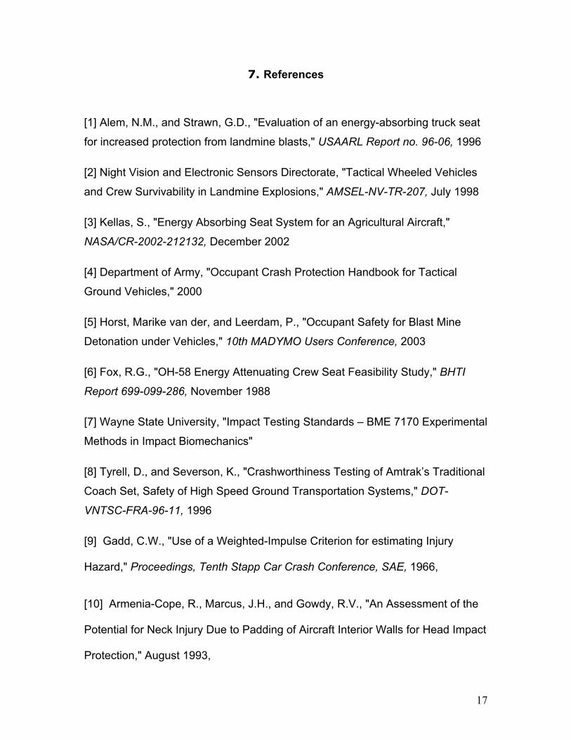
resultant acceleration injury criterion of 60 G in a 3 ms time interval. Figure 8
displays the effect of the contoured foam headrest cushion in providing constant
support to the head and neck and minimizing recoil. The peak magnitude of the
acceleration is 17 G compare to the higher peak magnitude of 31 G in the case
where the cushion was not made thicker behind the head. However both
magnitudes are still well within the resultant head acceleration injury criterion limit
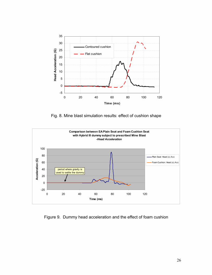
of 150 G. Figure 9 depicts the head acceleration of the dummy with an EA seat
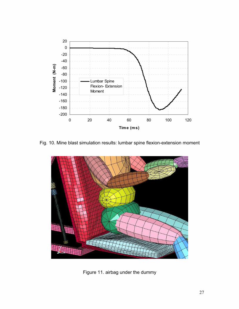
with cushioning and without cushioning. Figure 10 displays the lumbar spine
forward flexion and rearward extensional moments, with a peak magnitude of
184 N-m, which is well below the lumbar spine rearward extensional moment
injury criterion limit of 370 N-m. An airbag can also be placed between the seat
and the dummy bottom as shown in Figure 11. The mass flow rate in the air bag
can be controlled in such that it can reduce the pulse transmitted to the dummy.
Figure 12. depicts the x and the y-acceleration of the dummy’s head using the
various concepts presented here in.
15
6. Conclusions
The presented energy absorbing seat design proves to be effective in occupant
survivability during vertical drop and mine blast scenarios. Numerical simulations
of the energy absorbing seat subject to vertical drop tests and mine blast tests
with a dummy occupant prove to be reliable and a far less expensive alternative
to conducting destructive tests. From the numerical results of the simulations, it is
evident that the crushing of aluminum tubes provides a controlled, acceptable
means of attenuating deceleration pulses to survivable values. The use of a
contoured foam cushion helps in additionally attenuating the peak deceleration
pulse at the occupant’s lower torso, and the compressive lumbar load. The
contoured headrest ensures a minimal gap between the head and seat thereby
minimizing head rearward accelerations. Acknowledgements: The authors wish to express their gratitude to the Army
Research Laboratory and the Ohio Supercomputing Center for their financial and
computing support respectively.
16
7. References
[1] Alem, N.M., and Strawn, G.D., "Evaluation of an energy-absorbing truck seat
for increased protection from landmine blasts," USAARL Report no. 96-06, 1996
[2] Night Vision and Electronic Sensors Directorate, "Tactical Wheeled Vehicles
and Crew Survivability in Landmine Explosions," AMSEL-NV-TR-207, July 1998
[3] Kellas, S., "Energy Absorbing Seat System for an Agricultural Aircraft,"
NASA/CR-2002-212132, December 2002
[4] Department of Army, "Occupant Crash Protection Handbook for Tactical
Ground Vehicles," 2000
[5] Horst, Marike van der, and Leerdam, P., "Occupant Safety for Blast Mine
Detonation under Vehicles," 10th MADYMO Users Conference, 2003
[6] Fox, R.G., "OH-58 Energy Attenuating Crew Seat Feasibility Study," BHTI
Report 699-099-286, November 1988
[7] Wayne State University, "Impact Testing Standards – BME 7170 Experimental
Methods in Impact Biomechanics"
[8] Tyrell, D., and Severson, K., "Crashworthiness Testing of Amtrak’s Traditional
Coach Set, Safety of High Speed Ground Transportation Systems," DOT-
VNTSC-FRA-96-11, 1996
[9] Gadd, C.W., "Use of a Weighted-Impulse Criterion for estimating Injury
Hazard," Proceedings, Tenth Stapp Car Crash Conference, SAE, 1966,
[10] Armenia-Cope, R., Marcus, J.H., and Gowdy, R.V., "An Assessment of the
Potential for Neck Injury Due to Padding of Aircraft Interior Walls for Head Impact
Protection," August 1993,
17

[11] Kleinberger, M., Sun, E., and Saunders, J., "Effects of Head Restraint
Position on Neck Injury in Rear Impact," February 1999,
[12] McHenry, B.G., "Head Injury Criteria and the ATB," 2004,
[13] R. Nirula, "Correlation of Head Injury to Vehicle Contact Points using Crash
Injury Research and Engineering Network Data," Accident Analysis and
Prevention, Vol. 35, 2003, pp. 201.
[14] Teng, T., Chang, F., and Peng, C., "The Study of Head and Neck Injury in
Traffic Accidents," Journal of Applied Sciences, Vol. 4, No. 3, 2004, pp. 449-455.
[15] Welcher, J.B., and Szabo, T.J., "Relationships between Seat Properties and
Human Subject Kinematics in Rear Impact Tests," Accident Analysis and
Prevention, Vol. 33, 2001, pp. 289–304.
[16] Croft, A.C., Herring, P., and Freeman, M.D., "The Neck Injury Criterion:
Future Considerations," Accident Analysis and Prevention, Vol. 34, 2002, pp.
247-255.
[17] Bostrom, O., Svennson, M., and Muser, M., "NIC Measurement Techniques
and Result Interpretation," NIC Meeting, Gothenburg, 1998,
[18] Nusholtz, G.S., Domenico, L.D., and Shi, Y., "Studies of Neck Injury Criteria
Based on Existing Biomechanical Test Data," Accident Analysis and Prevention,
Vol. 35, 2003, pp. 777–786.
18

[19] Keeman, D., "An engineering approach to crashworthiness of thin walled
beams and joints in vehicle structures," Thin Walled Structures, Vol. 28, No. 3/4,
1997, pp. 309-320.
[20] Alghamdi, A. A. A., "Collapsible Impact Energy Absorbers: An Overview,"
Thin Walled Structures, Vol. 39, 2001, pp. 189-213
[21] Livermore Software Technology Corporation, "LS-DYNA Keyword User’s
Manual Version 970," 2003
19

TABLE 1: RECOMMENDED INJURY CRITERIA FOR LANDMINE TESTING [4]
HYBRID III Simulant
Response Parameter
Symbol (units) Assessment Reference Values
Head Injury Criteria
Head resultant acceleration
HIC
A (G)
750 ~5% risk of brain injury
150 G (2ms)
Neck forward flexion moment
Neck rearward extension moment
+ My (N-m)
- My (N-m)
190 N-m
57 N-m
Chest resultant acceleration A (G) 60 G (3ms), 40 G (7ms)
Lumbar spine axial compression force Fz (N) 3800 N (30ms), 6672 N (0ms)
Lumbar spine flexion moment
Lumbar spine extension moment
+ My (N-m)
- My (N-m)
1235 N-m
370 N-m
Pelvis vertical acceleration Az (G) 15, 18, 23 G (low, med, high risk)
Tibia axial compressive force
combined with Tibia bending moment
F (N)
M (N-m)
F/Fc – M/Mc < 1
where Fc=35,584N and Mc=225N-m
Femur or Tibia axial compression force Fz (N) 7562 N (10ms), 9074 N (0ms)
TABLE 2: DIMENSIONS AND PROPERTIES OF THE CYLINDRICAL ALUMINUM TUBES
Inner diameter (Di) 26.437 mm
Outer diameter (Do) 28.215 mm
Mean diameter (D) 27.326 mm
Thickness (t) 0.889 mm
Yield Strength (Y) 145 MPa
Length (L) 228.6 mm
Density (ρ) 2.610E-09 ton/mm3
Young’s modulus of Elasticity 68948.000 N/mm2
Poisson’s ratio 0.33
LSDYNA Material model Piecewise Linear Plasticity
Material model number 24
20

TABLE 3: CHARACTERISTICS OF THE SHELL AND IMPACTOR [15]
Shell Radius (mm) 11.875
Shell Thickness (mm) 1.65
Shell Length (mm) 106.68
Young’s Modulus (GPa) 72.4
Yield Stress (MPa) 295
Impact Speed (m/s) 4
Impactor Mass (kg) 262.5
Fig. 1. Axial crushing of cylindrical tube (a) initial configuration (b) initial formation
of three plastic hinges (c) formation of first lobe (d) completion of first fold and
initiation of second lobe formation (e) completion of first two folds and initiation of
third lobe (f) formation of third lobe
21

Fig. 2. Energy absorbing seat structure with Hybrid III dummy
0.00
0.20
0.40
0.60
0.80
1.00
1.20
1.40
1.60
1.80
0.00 0.20 0.40 0.60 0.80 1.00
Strain
Stre
ss (M
Pa)
Low Density Foam
Fig. 3. Nominal stress strain plot of the low density foam used
22

-20
0
20
40
60
80
100
0 20 40 60 8
Time (ms)
Acc
eler
atio
n (G
)
0
Vertical Drop TestPulse
-50
0
50
100
150
200
0 50 100 150
Time (ms)
Acc
eler
atio
n (G
)
Mine Blast Pulse
Fig. 4. Applied pulse simulating (a) impact after free fall (b) mine blast under
infantry vehicle
23

-60
-40
-20
0
20
40
0 10 20 30 40 50 6
Time (s)
Acc
eler
atio
n (G
)
0
Experiment
Simulation
-20
0
20
40
0 10 20 30 40 50 6Time (s)
Acc
eler
atio
n (G
)
0
Experiment
Simulation
Fig. 5. Comparison of experimental and simulation results (a) seat pulse
(b) occupant pulse
24

-40
-20
0
20
40
60
80
100
0 20 40 60 80 100 1
Time (ms)
Acc
eler
atio
n (G
)
20
Low er Torso
Seat
Structure
Fig. 6. Vertical drop test simulation results: acceleration
-20
-15
-10
-5
0
5
10
15
20
25
30
40 60 80 100 120
Time (ms)
Acc
eler
atio
n (G
)
Low er Torso
Seat
Chest
Fig. 7. Mine blast simulation results: acceleration
25
-5
0
5
10
15
20
25
30
35
0 20 40 60 80 100 1
Time (ms)
Hea
d A
ccel
erat
ion
(G)
20
Contoured cushion
Flat cushion
Fig. 8. Mine blast simulation results: effect of cushion shape
Comparison between EA Plain Seat and Foam Cushion Seatwith Hybrid III dummy subject to prescribed Mine Blast
-Head Acceleration
-20
0
20
40
60
80
100
0 20 40 60 80 100 120
Time (ms)
Acc
eler
atio
n (G
) Plain Seat: Head (x) Acc
Foam Cushion: Head (x) Acc
period where gravity isused to settle the dummy
Figure 9. Dummy head acceleration and the effect of foam cushion
26
-200-180
-160-140
-120-100
-80-60
-40-20
020
0 20 40 60 80 100 120
Time (ms)
Mom
ent
(N-m
)
Lumbar SpineFlexion- ExtensionMoment
Fig. 10. Mine blast simulation results: lumbar spine flexion-extension moment
Figure 11. airbag under the dummy
27

-8
-4
0
4
8
12
16
20
24
0 20 40 60 80 100 120 1Time (ms)
Acc
eler
atio
n (
G)
40
Head (x) Acc -Foam
Head (y) Acc -Foam
Head (x) Acc -Airbag
Head (y) Acc -Airbag
Figure 12. Head (x) and 9y) Acceleration
28