reduction in time to market of automotive seating system using ls-dyna
TRANSCRIPT

7th International LS-DYNA Users Conference Simulation Technology (2)
9-17
Reduction in Time to Market of Automotive Seating System Using LS-DYNA
Hurshkumar G Donde Infosys Technologies Limited
Electronics City, Bangalore 561 229 INDIA. [email protected]
Rakesh K Lad Infosys Technologies Limited
Electronics City, Bangalore 561 229 INDIA. [email protected]
Prabal Kumar Biswas Infosys Technologies Limited
Electronics City, Bangalore 561 229 INDIA. [email protected]
Praveen B Patil Infosys Technologies Limited
Electronics City, Bangalore 561 229 INDIA. [email protected]
Gordon Stace Johnson Control Automotive UK Limited
Chelmsford, Essex UK [email protected]
Keywords: ��������������� �����������������������������������������������
��������������

Simulation Technology (2) 7th International LS-DYNA Users Conference
9-18
ABSTRACT The worldwide automotive industry is going through a sea change in order to get the share in the global market, which is becoming highly competitive & dynamic. The automotive OEM’s are faced with conflicting demands & challenges. There is an increasing demand for cost & weight reduction, fuel economy & reduction in time to market on one hand and on the other hand there is even more increasing demand towards assuring improved occupant safety and comfort in complex crash & driving conditions besides the pressure from environmental regulations. The safety and environmental regulations are becoming increasingly stringent in the developed economies & the developing economies are catching up. These factors are driving the change in entire automotive industry value chain and the major sub systems suppliers are directly affected by this. One such sub-system is seating system, as it is major contributor to the occupant safety & comfort. The automotive seating system development process is becoming highly complex and challenging as the regulations pertaining to NVH (Noise, Vibration & Harshness)/ durability/ fatigue, static/dynamic strength and crash safety are becoming increasingly stringent besides OEM’s pressure to reduce weight and cost. One of the major challenges is to reduce the time and the cost of developmental prototyping and testing. As a result most of the forward-looking organisations are beginning to move towards Virtual Product Development Environment (VPD). One of the most useful tools available to virtually simulate product performance under various dynamic conditions is LS-DYNA. This paper depicts the evolution of a rear seat system for the Ford Focus vehicle through effective use of LS-DYNA and other CAE tools, throughout the developmental life cycle. This program demanded a reduced program timeline of 18 months.
INTRODUCTION In the year 2000, 41,821 people were killed in 6,394,000 police reported motor vehicle traffic crashes in US alone and 3,189,000 people were injured. [6]. Passenger car accounted for 57 % of total fatalities. In recent years the occupant safety is gaining major attention during the design of seating system making it mandatory to assess the performance of seating system with restraint system, airbag and vehicle interfaces to ensure occupant safety. As per the ECE regulations [8], [9], providing 3 point restraint system for forward facing rear seats of passenger cars is mandatory for 2002 European car models. The rear seating system thus has to withstand the additional load due to occupant during forward impact besides loads due to inertia of the seat and luggage load. In order to ensure occupant safety the seating system should absorb considerable energy during crash event besides satisfying the limits on peak dynamic and residual deflections.
BACKGROUND This paper depicts the evolution of a rear seat with enhanced features from an existing seat for Ford Focus having 60-40 split cushion & rear seat back (RSB) configuration as shown in Figure1. The RSB is made of sheet metal pressed components. Centre hinge mechanism facilitates the tipping of 40% and 60% RSB about pivot axis to provide extra stowage space.
Figure 1: 60-40 Rear seat configuration

7th International LS-DYNA Users Conference Simulation Technology (2)
9-19
For the 2002MY-launch car, Ford wanted to redesign the rear seat with major feature enhancements as given below (Figure 2).
• Addition of a feature, which will serve as armrest as well as stowage tray • This seat needed to offer various configurations as shown in Figure 2. • The rear seat back (RSB) to have 40-20-40 split
Figure 2. Configurations Expected of New Seat
SEATING SYSTEM DEVELOPMENT LIFE CYCLE In order to meet the above challenges, Johnson Controls Inc. (JCI) and Infosys undertook a project involving major redesign work. Stringent timeline of 18 months was available to complete the task of designing, testing, tooling-and-prototyping and homologation. The design challenges posed were -
• 60% part of rear seat back needed to be further split to accommodate armrest 20% RSB) • Latch and locking mechanism to be introduced for holding the 20% armrest • Retractor mounting to be redesigned • Central hinge needed modifications • Rear seat back fold flat • Latch area reinforcement
The product development process used by JCI for an integrated idea-to- Launch process (Product Launch system -PLUS process) is shown in Figure 3
Figure 3. Product Launch System used by Johnson Controls Inc.
Design Position 20 % Folded Position
40% Folded Position 60% Folded Position

Simulation Technology (2) 7th International LS-DYNA Users Conference
9-20
It connects many different disciplines involved in product development. The major amount of time in a product development life cycle is spent on the development and design & verification. These processes are iterative and involve time and money. In order to meet the program timeline, VPD approach developed by Infosys & JCI was used and is depicted in the Figure 4 below.
Figure 4. Development Approach During the development phase, LS-DYNA was used extensively to evaluate product performance, access occupant safety/injury and provide design/development directions. This resulted in reducing the time required for converging to the optimum solution and also number of iterations of making prototypes and testing.
CONCEPT SELECTION, A CRUCIAL STAGE IN DEVELOPMENT
Most of the total product cost is committed during the early stage of the program. The cost for tooling, material, mechanisms, restraint systems, safety devices, seat accessories etc for the potential concept of the seat is committed in the design phase. The bulk of money is actually spent quite late in the program. Hence it is very expensive to rollback for concept itself in later stage of program. This can be realised by Figure 5. Realizing the impact of right concept selection on the project cost and time, utmost care was taken to select the right concept as potential product.
Figure 5. Typical proportion of cost committed at various stages
0
2 0
4 0
6 0
8 0
1 0 0
T i m e
Co
st %
C o m m i t e d
S p e n t
D e s i g n D e v e l o p m e n t M a n u f a c t u r i n g

7th International LS-DYNA Users Conference Simulation Technology (2)
9-21
CONCEPT EVOLUTION The first step was to arrive at alternative concepts/ configurations, satisfying functionality requirements besides satisfying the packaging requirements. The 60% rear seat back was partially split in 40% & 20%, the 20% panel itself serving as armrest and stowage tray. Various reinforcement schemes for partial split in 60% RSB were evaluated. The next step was to estimate of the loads experienced by components, sub systems and mechanisms for the proposed design, using the existing seat configuration as basis (Refer Figure 6a and Figure 6b).
Figure 6a. Simple mathematical Model for 60-40 seat
Nomenclature H1 Outboard hinge RH H2 Inboard hinge
H3 Outboard hinge LH L1 Outboard latch RH
F1, F2, F3 Floor L2 Outboard latch LH
Figure 6b. Simple mathematical Model for proposed 40-20-40 seat Nomenclature
H1 Outboard hinge RH H2 Inboard hinge - 40 % H3 Outboard hinge LH H4 Inboard hinge - 20% H5 20% - 40% hinge L1 Outboard latch RH F1, F2, F3 Floor L2 Outboard latch LH L3 Hinge 20% - 40%

Simulation Technology (2) 7th International LS-DYNA Users Conference
9-22
In order to evaluate the load path and load distribution at critical zones, the worst load case scenarios were arrived at using the safety regulations (ECE) and OEM’s specification that were to be met by the seating system under various crash/dynamic conditions. Simplified FE models were created (Refer Figure 7) to identify worst loads and load path. Here the hinges and pivots are represented by appropriate boundary conditions. Various configurations of the FE model were considered with possible permutations of hinges and pivots in locked and unlocked condition.
Figure 7. Simplified Fe Model of the Seating System Concepts Static loads equivalent of dynamic load for forward, rearward and luggage crash conditions were applied to the model. These are arrived as given below:
Load Case Loads Forward Manikin load at Retractor mounting on seat + Inertia load Rearward Manikin load +Inertia load Luggage Inertia load + Luggage load
The comparison of the forces at critical areas for 40-60% and 40-20-40% seat configurations is as given below:
Location 40-60 Seat Structure Maximum Resultant Force (kN)
40-20-40 Seat Structure Maximum Resultant Force (kN)
H1 8.50 8.5 H2 35.0 40 H3 11.60 15 L1 7.48 7.5 L2 11.80 13.50 H4 - 14 H5 - 9.0
Table 1. Forces at various mountings The initial estimate of the forces at various locations helped in sizing of various components and hastened the process of transforming the concepts into engineering proposals. Some of the key observations are explained below.

7th International LS-DYNA Users Conference Simulation Technology (2)
9-23
The resultant forces and moments experienced at In-Board hinge are found to increase due to the 20% panel mounting conditions. To withstand this the IB hinge was required to be stronger than 40-60% hinge. Also the forces and moments at 20% mounting locations were found to be significant due to the luggage loading. Based on these inputs, several concepts were developed to provide reinforcements to the split 60% RSB (hence forth called as L-shaped RSB). Two major philosophies in concept selection were evaluated i.e. tubular construction and sheet metal pressing. The conventional pressed components are preferred for manufacturing but needs a higher gauge and deep drawing to achieve higher stiffness. The tubular concept on other hand provides good strength but needs proper designing and layout for reducing manufacturing cost and achieving tolerances in interface areas.
CONCEPT SELECTION The estimated forces based on simplified FE model were used to compare the tubular concept with pressed concepts. The basic assumptions made were that all the hinges are locked and Latch offers no resistance to rotation about y- and z-axis. The various load cases were considered for the static analysis and the following results were obtained.
LOAD CASE PRESSED CONCEPT Maximum deflection
TUBULAR CONCEPT Maximum deflection
1 Forward 177 mm 142 mm 2 Rearward 346mm 279mm 3 Luggage 74 mm 56mm
Table 2. Comparison of two concepts The hollow tubes in tubular concept were found to be contributing significantly to the stiffness of the seat back and met the packaging space requirements as well. Component wise stresses and strains were within safe limits. Also the buckling factor for tubular structure was significantly higher than that of pressed concept.
STRUCTURAL DEVELOPMENT OF THE SEATING SYSTEM Considering the volume of production, tooling cost & time to market, tubular structure concept was chosen as candidate for developing seating system. The seating system was developed based on this and the performance was constantly monitored/ assessed using LS-DYNA. In order to achieve integrity of the structure and acceptable performance it was evident that proper design of reinforcement brackets at critical interfaces such as the tube-to-tube, tube-to-latch, tube-to-hinge was utmost importance. Early in the development cycle, simplified analysis was carried out to evaluate the reinforcement bracket concepts to quickly arrive at feasible design. One such example is depicted in the Figure 8. This approach helped in quick design convergence besides selection of gauge & material grade.
Figure 8. Stress Plot of reinforcement bracket

Simulation Technology (2) 7th International LS-DYNA Users Conference
9-24
Another critical step was to design the mechanisms and evaluate the strength of these in various configurations of the seating system. The centre Hinge mechanism was developed to enable tipping of 40%& 20% RSB panel together as well as 20% panel separately (Refer Figure 2). A Micro Latch Mechanism was introduced to enable independent movement of the 20% panel with respect to the 40% panel. These mechanisms were studied at subsystem level and later evaluated with complete FE model.
DYNAMIC PERFORMANCE EVALUATION USING LS-DYNA After the structural development reached considerable degree of maturity, the further development was steered based on critical evaluations by performing series of quasi-static and dynamic simulations using LS-DYNA. FE model of the seating system was created using HYPERMESH [1] as shown in Figure 9. The refinements of the model followed every development and design modification. The FE model of seat consisted of major structural assemblies such as rear seat back, latch, hinge, cushion, seat belt, retractor, mounting bracket etc. Spotwelds were simulated using nodal rigid bodies. Bar elements were used to simulate bolts, pins and rivets. LS-DYNA [4], [5] joints were used for simulating pivots. In general, QUAD4 and TRIA3 shell elements with three integration points along the thickness were used. Contacts between interfacing parts were provided. 95th percentile Hybrid III male manikin restrained by three-point belt was used. The mechanisms were appropriately represented.
Figure 9. FE model for LS-DYNA Simulation Following assumptions were made for the simulations. • Representative floor was used with proper contacts defined at seat structure interfaces. • Mechanisms failure was not considered. The FE models of the seat were subjected to analysis as per the ECE and OEM requirements. The summary of crucial tests for design verification for C170 rear seat is given in Table 3 below.
Latch
Retractor Pressing Latch
40% LH Main Tube
40% RH Main Tube 40% Vertical Tube
Pivot Bracket

7th International LS-DYNA Users Conference Simulation Technology (2)
9-25
S.No. Regulation Description Pass Criteria
1 ECE R17
Luggage retention
2 Luggage Boxes each of 18 Kg (300 mm X 300 mm X 300 mm) placed at a distance 200-mm behind the Seat Back.
Any part of seat back must not move forward of a 100 mm transverse vertical plane with respect to R-point. The test blocks should not intrude into the passenger space
2 OEM Forward Impact Specification
Luggage boxes of greater mass than ECE17 with 95% Hybrid III manikin placed at centre seat and attached with seatbelt.
Latches, hinges and floor attachments must hold Luggage must not to intrude in passenger area.
3 ECE R14 Belt pull test
13.5 kN force applied on upper torso and lap body block attached to belt system plus 20 times seat weight applied at seat centre of gravity
Anchorage must be capable to withstand the load and the permanent deformation including rupture or breakage of any anchorage or surrounding area shall not constitute failure.
Table 3. Crucial Tests to be qualified by seating system In case of dynamic simulation, the seat assembly (floor) was subjected to impact pulse as shown in Fig 10 below. The entire seating system was subjected to gravitational load.
Figure 10. HyGee 25g Forward Impact Pulse

Simulation Technology (2) 7th International LS-DYNA Users Conference
9-26
Quasi-static analysis using LS-DYNA was performed to simulate the seat belt anchorage pull test as per ECE R14. The loads were applied gradually in time domain and maintained constant after ramping up to the full load, until the response of the structure stabilised.
Figure 11. Deformed Structure (OEM’s forward Impact load case)
The analysis performed on the structure revealed valuable insight into the structural performance and helped in identifying the weak areas. The structural deformation for forward Impact simulation is depicted in the figure 11 above. Careful study of the simulation results led to valuable design inputs as shown in the Table 3 below.
Observations
ECE R17 OEM ECE R14
Inboard mounting brackets failing due to luggage direct hit.
Inboard mounting brackets are failing due to luggage direct hit
Significant twist in the main tube responsible for high deflection
Crumpling of vertical tube in the area of luggage hit
Crumpling of vertical tube in the area of luggage hit
Retractor mounting pressing weak
Latch reinforcement brackets weak
Retractor mounting pressing weak.
Latches and inboard hinges weak
The Forces and moments at hinges, mechanisms and vehicle interfaces were obtained for all the three simulations and the worst-case load was taken for component design improvements. The component-wise internal energies were studied to understand the contribution of components in crash energy absorption. Based on the above observations/recommendations, necessary design changes were carried out in the seat structure, keeping in view the package space and manufacturing feasibility.
7th International LS-DYNA Users Conference Simulation Technology (2)
9-27
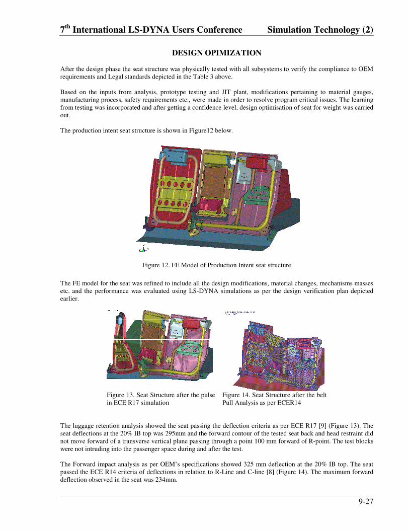
DESIGN OPIMIZATION After the design phase the seat structure was physically tested with all subsystems to verify the compliance to OEM requirements and Legal standards depicted in the Table 3 above. Based on the inputs from analysis, prototype testing and JIT plant, modifications pertaining to material gauges, manufacturing process, safety requirements etc., were made in order to resolve program critical issues. The learning from testing was incorporated and after getting a confidence level, design optimisation of seat for weight was carried out. The production intent seat structure is shown in Figure12 below.
Figure 12. FE Model of Production Intent seat structure
The FE model for the seat was refined to include all the design modifications, material changes, mechanisms masses etc. and the performance was evaluated using LS-DYNA simulations as per the design verification plan depicted earlier.
Figure 13. Seat Structure after the pulse in ECE R17 simulation
Figure 14. Seat Structure after the belt Pull Analysis as per ECER14
The luggage retention analysis showed the seat passing the deflection criteria as per ECE R17 [9] (Figure 13). The seat deflections at the 20% IB top was 295mm and the forward contour of the tested seat back and head restraint did not move forward of a transverse vertical plane passing through a point 100 mm forward of R-point. The test blocks were not intruding into the passenger space during and after the test. The Forward impact analysis as per OEM’s specifications showed 325 mm deflection at the 20% IB top. The seat passed the ECE R14 criteria of deflections in relation to R-Line and C-line [8] (Figure 14). The maximum forward deflection observed in the seat was 234mm.

Simulation Technology (2) 7th International LS-DYNA Users Conference
9-28
PHYSICAL TESTING (FINAL DESIGN VALIDATION) The production intent seat was tested as per the OEM’s and Legal regulations. The seat passed the ECE R17 testing with slight modifications (Refer Figure 15a and Figure 15b) and the dynamic deflections and static deformations were found to be in close agreement with simulation results.
Figure 15a. ECE R 17 Test Set Up Figure 15b. Seat Structure after ECE17
Test A good co relation was obtained for ECE R14 test (refer Figure 16). The seat tested for belt pull anchorage test gave the static deflection value of 228mm while the LS-DYNA simulation showed static deflection 234mm.
Figure 16. Seat Structure after ECE 14 Test
CONCLUSIONS
Effective use of computer simulation tools such as LS-DYNA for virtual product development helped in developing the seating system in compressed timeline of 18 months. The reduction in number of physical testing attempts to develop a seat that qualified the OEM and legal requirements resulted in reduced design cost. Besides this, the following specific advantages were obtained
• Quick evaluating design changes at later stages of design phase • Weight reduction • Design improvements • Robust design complying to safety standards (ECE17, ECE14 etc)

7th International LS-DYNA Users Conference Simulation Technology (2)
9-29
ACKNOWLEDGEMENTS The authors would like to thank M/s Johnson Controls for granting the permission to publish the information, providing encouraging environment and valuable support. The authors would like to thank M/s Infosys Technologies for providing all the infrastructure and technical support to execute the analysis work. The authors greatly acknowledge the valuable guidance, technical and morale support provided by Mr. Sean Colegate, Chief Engineer, Ford Business Unit, throughout the project.
REFERENCES 1. Altair Hypermesh V4.0 On-Line Manual, (Altair Engineering Inc., Troy, MI, 2000)
2. Altair Optistruct V4.0 On-Line Manual, (Altair Engineering Inc., Troy, MI, 2000)
3. Eddie Norman Joyce Riley Syd Urry Mike Whittaker Advance Design and Technology Handbook PP 75-76.
4. Hallquist, J.O., LS-DYNA, Theoretical Manual, (Livermore Software Technology Corporation, Livermore, CA, 1997)
5. LS-DYNA Keyword Users manual Non Linear Dynamic Analysis of the structure May 1999 Version 950
6. National Highway Traffic Safety Administration, Traffic Safety Facts 2000 A Public Information Fact Sheet on Motor Vehicle andTraffic Safety Published by the National Highway Traffic Safety Administration’s National Center for Statistics and Analysis
7. Schramn, U., and Pilkey, W.D., Review: Optimal design of Structures under impact Loading, Shock and Vibration 3 (1996)
8. United Nations Agreement. Reg. Name: UN/ECE Seat Belt Anchorages Reg. Number ECE-14.05
9. United Nations Agreement. Reg. Name: UN/ECE Strength of seat & their anchorages. Reg. Number ECE-17.07

Simulation Technology (2) 7th International LS-DYNA Users Conference
9-30