reduced energy consumption through projectile based excavation quarterly technical...
TRANSCRIPT

Reduced Energy Consumption Through Projectile Based Excavation
Quarterly Technical Progress Report
10/01/02 - 12/31/02
Author: Mark Machina
January 9, 2002
Contract: DE-FC26-01NT41059
Prepared by:
Advanced Power Technologies, Inc. 1400-A Duke Street
Alexandria, VA 22314 703-549-2412
Submitted to:
NETL AAD Document Control Bldg. 921 U.S. Department of Energy
National Energy Technology Laboratory P.O. Box 10940
Pittsburgh, PA 15236-0940

Advanced Power Technologies, Inc., 1400-A Duke Street, Alexandria, Virginia 22314, (703) 549-2412, Fax (703) 549-2459 1
Disclaimer. This report was prepared as an account of work sponsored by an agency of the United States Government. Neither the United States Government nor any agency thereof, nor any of their employees, makes any warranty, express or implied, or assumes any legal liability or responsibility for the accuracy, completeness, or usefulness of any information, apparatus, product, or process disclosed, or represents that its use would not infringe privately owned rights. Reference herein to any specific commercial product, process, or service by trade name, trademark, manufacturer, or otherwise does not necessarily constitute or imply its endorsement, recommendation, or favoring by the United States Government or any agency thereof. The views and opinions of authors expressed herein do not necessarily state or reflect those of the United States Government of any agency thereof. Abstract. The Projectile Based Excavation (ProjEX) program has as its goal, the reduction of energy required for production mining and secondary breakage through the use of a projectile based excavation system. It depends on the development of a low cost family of projectiles that will penetrate and break up different types of ore/rock and a low cost electric launch system. The electric launch system will eliminate the need for high cost propellant considered for similar concepts in the past. This document reports on the progress made in the program during the past quarter. It reports on projectile development experiments and the development of the electric launch sys tem design.
Table of Contents Progress to Date 2 Experimental Field Experiments 2 Experimental Apparatus 6 Results and Discussion
Electric Launch Discussion 8 Conclusion Hypothesis and Conclusions 9 Problems Encountered 9 Plans for Next Reporting Period 9 Prospects for Future Progress 9 References N/A to this Report
Advanced Power Technologies, Inc., 1400-A Duke Street, Alexandria, Virginia 22314, (703) 549-2412, Fax (703) 549-2459 2
Technical Progress Report
Contract: DE-FC26-01NT41059
Reduced Energy Consumption Through Projectile Based Excavation
COR: Mr. Mike Mosser
1. Progress to date. During the past quarter, field/quarry testing with the 60 mm system continued, but again, at a greatly reduced pace. The investigation of the accident (unrelated to this program, but involving a Lafarge subcontractor) reported in the last report and the continued Lafarge union negotiations caused a cessation of quarry testing for most of the quarter. The investigation of possible realignment of the program to focus on Secondary Breakage, rather than production mining continued with the search for mining industry partners.
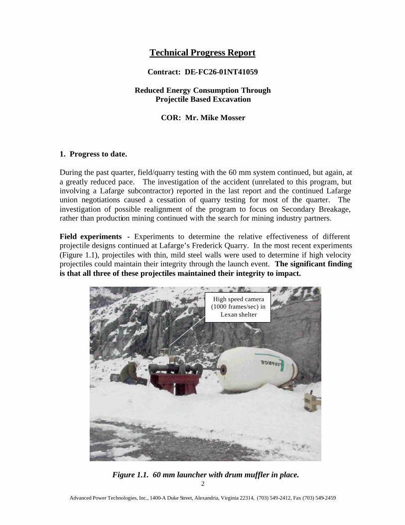
Field experiments - Experiments to determine the relative effectiveness of different projectile designs continued at Lafarge’s Frederick Quarry. In the most recent experiments (Figure 1.1), projectiles with thin, mild steel walls were used to determine if high velocity projectiles could maintain their integrity through the launch event. The significant finding is that all three of these projectiles maintained their integrity to impact.
Figure 1.1. 60 mm launcher with drum muffler in place.
High speed camera (1000 frames/sec) in
Lexan shelter

Advanced Power Technologies, Inc., 1400-A Duke Street, Alexandria, Virginia 22314, (703) 549-2412, Fax (703) 549-2459 3
Frame a.
Frame b.
Figure 1.2. Two frame sequence from high speed camera catches Shot #1 projectile leaving velocimeter (Frame a.) and penetrating wall, having passed through witness
plate (Frame b).
Velocimeter Witness Plate
Advanced Power Technologies, Inc., 1400-A Duke Street, Alexandria, Virginia 22314, (703) 549-2412, Fax (703) 549-2459 4
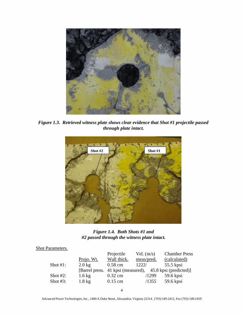
Figure 1.3. Retrieved witness plate shows clear evidence that Shot #1 projectile passed through plate intact.
Figure 1.4. Both Shots #1 and #2 passed through the witness plate intact.
Shot Parameters. Projectile Vel. (m/s) Chamber Press
Projo. Wt. Wall thick. meas/pred. (calculated) Shot #1: 2.0 kg 0.58 cm 1222/ 55.5 kpsi
[Barrel press. 41 kpsi (measured), 45.8 kpsi (predicted)] Shot #2: 1.6 kg 0.32 cm /1299 59.6 kpsi Shot #3: 1.8 kg 0.15 cm /1355 59.6 kpsi
Shot #1 Shot #2

Advanced Power Technologies, Inc., 1400-A Duke Street, Alexandria, Virginia 22314, (703) 549-2412, Fax (703) 549-2459 5
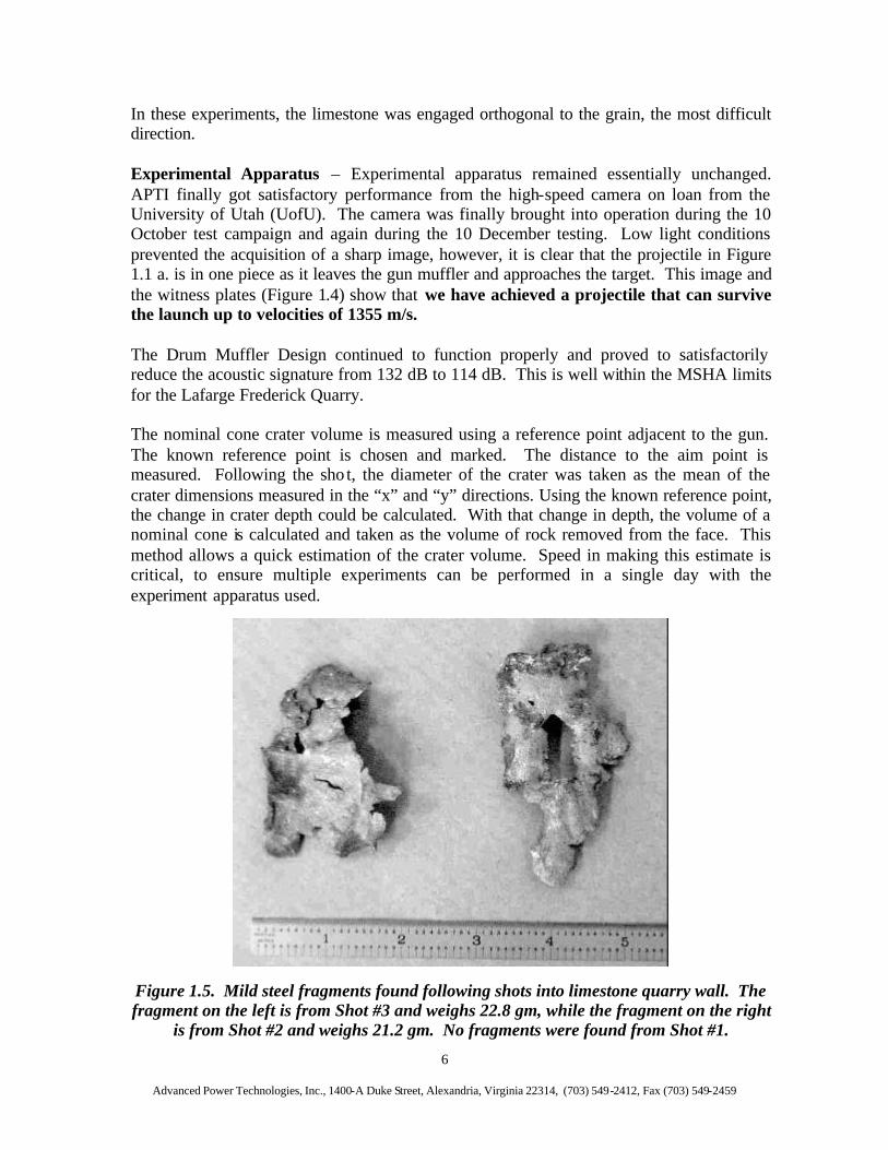
The difference between measured and predicted barrel pressure is to be expected. As suggested in Figure 1.1, the ambient temperature was relatively low and therefore some degradation in performance is normal. More likely, the cause was the obturator used on these prototype rounds, which was fabricated by hand in the laboratory and is considered less than optimal. Velocities for Shots 2 and 3 are calculated based on pressure readings. Fragments. The very few fragments found following the shots show that the thin steel case literally tore apart. The tears in the metal (Figure 1.5) indicate that the fragments were in the process of failing in many places when they broke free. The small number of fragments found suggests that they are small enough to be lost (not identifiable during stirring of the muck and observation with the eye) in the muck created by the shots. These are small enough to pass through primary crushers and are easily deformed. They weigh 22.8 gm and 21.2 gm respectively from left to right. Figure 1.6 includes samples of fragments resulting from nose cones of concrete rounds fired in earlier experiments. These projectiles failed at velocities above 1000 m/s. The figure is included for comparison and can be seen to be roughly the same size as those from the thin steel walled projectiles, but thicker. They weigh 60.4 gm and 202.5 gm respectively from left to right. Muck Production. Using the “nominal cone crater” volume calculation described below in Experimental Apparatus , the production of the three shots can be characterized as follows.
Projo. Wt. Wall thick. Velocity K.E. (MJ) Muck produced ton/MJ Shot #1 2.0 kg 0.58 cm 1222 m/s 1.5 0.19 m3, 0.48 ton 0.32 Shot #3 1.6 kg 0.32 cm 1299 m/s 1.35 0.29 m3, 0.74 ton 0.55 Shot #2 1.8 kg 0.15 cm 1355 m/s 1.65 0.14 m3, 0.36 ton 0.22 The projectiles were fired the order given by “Shot #” to improve the probability of successful data retrieval. The largest production was achieved by the third shot fired as would be expected, since it was able to take advantage of the cracking produced by the two earlier shots. This result is similar to those achieved by APTI in other programs where multiple shots were taken into a single target. Based on past experience, if many shots could be taken into the mine face, as would be the case in a production situation, the production of individual shots would vary greatly, but the mean production per shot would be greater. Three shots are not normally enough to achieve the full mean capability of a projectile, therefore, these results are taken to be conservative. Another factor effecting production is the projectile velocity. A production system would likely fire at approximately 1.5 km/s. This higher velocity increases the kine tic energy of the impact significantly and therefore would be expected to increase the muck production.
Advanced Power Technologies, Inc., 1400-A Duke Street, Alexandria, Virginia 22314, (703) 549-2412, Fax (703) 549-2459 6
In these experiments, the limestone was engaged orthogonal to the grain, the most difficult direction.
Experimental Apparatus – Experimental apparatus remained essentially unchanged. APTI finally got satisfactory performance from the high-speed camera on loan from the University of Utah (UofU). The camera was finally brought into operation during the 10 October test campaign and again during the 10 December testing. Low light conditions prevented the acquisition of a sharp image, however, it is clear that the projectile in Figure 1.1 a. is in one piece as it leaves the gun muffler and approaches the target. This image and the witness plates (Figure 1.4) show that we have achieved a projectile that can survive the launch up to velocities of 1355 m/s. The Drum Muffler Design continued to function properly and proved to satisfactorily reduce the acoustic signature from 132 dB to 114 dB. This is well within the MSHA limits for the Lafarge Frederick Quarry. The nominal cone crater volume is measured using a reference point adjacent to the gun. The known reference point is chosen and marked. The distance to the aim point is measured. Following the sho t, the diameter of the crater was taken as the mean of the crater dimensions measured in the “x” and “y” directions. Using the known reference point, the change in crater depth could be calculated. With that change in depth, the volume of a nominal cone is calculated and taken as the volume of rock removed from the face. This method allows a quick estimation of the crater volume. Speed in making this estimate is critical, to ensure multiple experiments can be performed in a single day with the experiment apparatus used.
Figure 1.5. Mild steel fragments found following shots into limestone quarry wall. The fragment on the left is from Shot #3 and weighs 22.8 gm, while the fragment on the right
is from Shot #2 and weighs 21.2 gm. No fragments were found from Shot #1.
Advanced Power Technologies, Inc., 1400-A Duke Street, Alexandria, Virginia 22314, (703) 549-2412, Fax (703) 549-2459 7
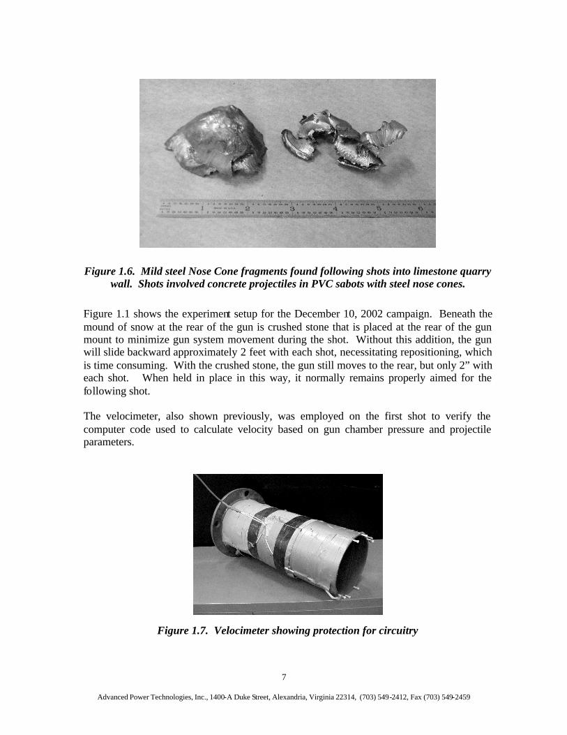
Figure 1.6. Mild steel Nose Cone fragments found following shots into limestone quarry wall. Shots involved concrete projectiles in PVC sabots with steel nose cones.
Figure 1.1 shows the experiment setup for the December 10, 2002 campaign. Beneath the mound of snow at the rear of the gun is crushed stone that is placed at the rear of the gun mount to minimize gun system movement during the shot. Without this addition, the gun will slide backward approximately 2 feet with each shot, necessitating repositioning, which is time consuming. With the crushed stone, the gun still moves to the rear, but only 2” with each shot. When held in place in this way, it normally remains properly aimed for the following shot. The velocimeter, also shown previously, was employed on the first shot to verify the computer code used to calculate velocity based on gun chamber pressure and projectile parameters.
Figure 1.7. Velocimeter showing protection for circuitry
Advanced Power Technologies, Inc., 1400-A Duke Street, Alexandria, Virginia 22314, (703) 549-2412, Fax (703) 549-2459 8
Projectile designs – As mentioned in the last quarterly report, new designs have been developed that will survive high speed launch. These designs were fashioned after the work performed by Physics International (PI) in the early 1970s, but include new concrete/grout products with increased strength. Figure 1.8 shows a typical design for the new projectiles.
Figure 1.8 Projectile design modification to improve ability to maintain integrity during high speed launch.
Projectile shells with wall thicknesses of 0.06”, 0.125” and 0.23” were fabricated from mild steel for testing. They were filled with high strength concrete prior to firing. The PI designs used high strength Aluminum for the casing. The mild steel used here is far less costly, and of roughly the same tensile strength. The goal was to find a projectile wall strength that will survive the acceleration in the gun barrel and release from the muzzle, but not result in large fragments in the muck. A fully assembled 60 mm round of the new design is shown in Figure 1.9. The dark, striped covering on the projectile is vinyl tape which constituted the obturator.

Advanced Power Technologies, Inc., 1400-A Duke Street, Alexandria, Virginia 22314, (703) 549-2412, Fax (703) 549-2459 9
Figure 1.9. Fully assembled 60 mm round ready to fire.
Hypothesis and Conclusion The hypothesis that a low cost projectile can be produced that will effectively excavate rock for production mining was proven to be true. In the most recent experiment campaign, a projectile with a thin steel case filled with concrete excavated nearly 1 ton of rock (0.29 m3) even though it was fired at less than the ultimately planned 1.5 m/s. This did not meet the goal of 1 m3 per shot and was less than the 0.4 m3 achieved by a heavy nose cone projectile shot taken at higher velocity in an earlier campaign. It did show, however, that projectiles with low cost, thin steel shells can survive the acceleration to high velocity (greater than 1 km/s) and achieve reasonable excavation in limestone. Electric Launch Discussion. The design of the electric launch subsystem was reviewed. The design of the Pulse Forming Network (PFN) and cost quotes from supporting vendors were verified. We were unable to identify any significant cost reductions with this review. Therefore, the development of the prototype electric launch subsystem remains out of reach with the current funding level. It had been hoped that more of the equipment required for the electric launch subsystem could be obtained from the Department of Defense, however, this has not proven possible. 2. Problems encountered. The price reductions sought during the electric launch system review did not materialize, leaving the electric launch system development out of reach with the funding level of the program. To date, new industrial partners who will contribute funding as part of the matching funds effort have not been found. 3. Plans for next reporting period. During the coming report period, plans call for the following.
• Realignment of the program to focus on Secondary Breakage if possible. • Identifying new industrial partners who will support the development of a
Secondary Breakage system. 4. Prospects for future progress. A realignment of the program to focus on Secondary Breakage would be an excellent move. The use of a projectile based approach to Secondary Breakage will result in cost and energy savings, especially if the primary crushing step can be eliminated. To achieve this, however, the initial propellant launch system would have to be replaced with an electric launch system, which would have a lower operating cost. The long-range development of an electrical firing system may be possible in the coming Phase III if a supportive industrial partner can be found. If initial field tests prove effective, the program will move to the electrical launch design quickly. However, without the cash contribution of an industrial partner, pursuit of the Secondary Breakage objective is doubtful.