redcat. the essential tool for researchers
TRANSCRIPT
The Electrochemical Society Interface • Summer 2012 37
Redcat. The essential tool for researchers.
• Discover cutting-edge research
• Connect with peers
• Share your content and ideas
• Find future employers and employees
TM
research • news • events • resources | search • explore • connec t • share • d iscover
for everyone in electrochemistry and solid state science and technology
© 20
11 by
The E
Lectr
oche
mica
l Soc
iety;
all rig
hts r
eser
ved.
C
M
Y
CM
MY
CY
CMY
K
redcat_ad_IF_Sp2012_1.pdf 1 8/1/2012 9:04:52 AM
Lithium ion rechargeable batteries seem to be everywhere—they provide power for most portable electronics, an
increasing number of hand tools, as well as the latest types of Battery Electric Vehicles (BEVs, such as Nissan Leaf and Tesla Roadster) and Extended-Range Electric Vehicles (E-REV such as Chevy Volt).
Safety is a key aspect of any energy storage device, including batteries. When discussing battery safety, it is important to understand that batteries contain both the oxidizer (cathode) and fuel (anode) in a sealed container. (This is rarely done—other examples are high explosives and rocket propellant.) Under normal operation, the fuel and oxidizer convert the chemical energy to electrical energy with minimal heat and negligible gas. If allowed to react chemically in an electrochemical cell, the fuel and oxidizer convert the chemical energy directly into heat and gas. Once started, chemical reaction will likely proceed to completion because of the intimate contact of fuel and oxidizer.
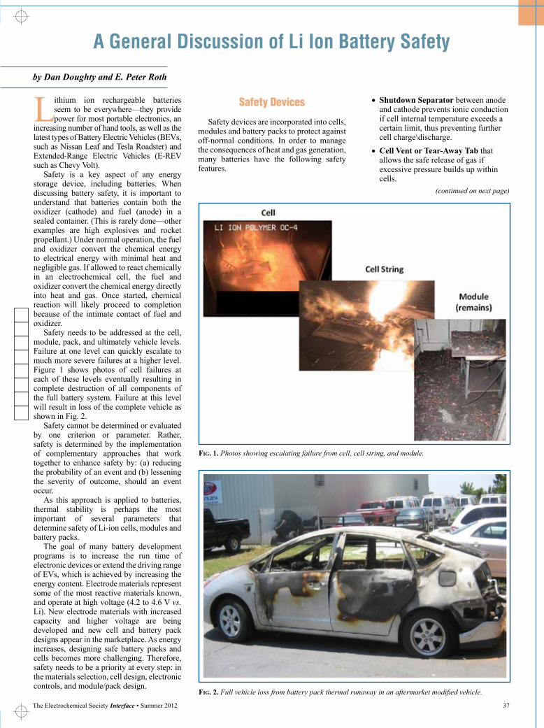
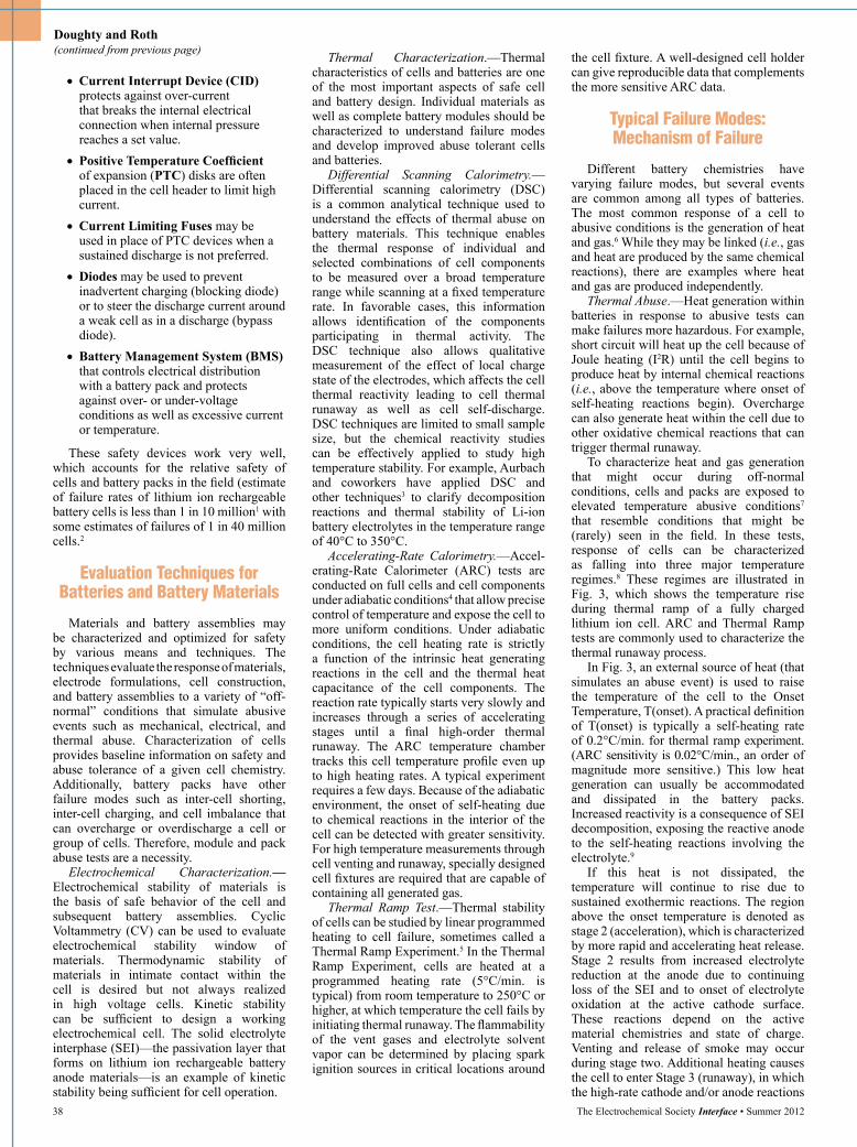
Safety needs to be addressed at the cell, module, pack, and ultimately vehicle levels. Failure at one level can quickly escalate to much more severe failures at a higher level. Figure 1 shows photos of cell failures at each of these levels eventually resulting in complete destruction of all components of the full battery system. Failure at this level will result in loss of the complete vehicle as shown in Fig. 2.
Safety cannot be determined or evaluated by one criterion or parameter. Rather, safety is determined by the implementation of complementary approaches that work together to enhance safety by: (a) reducing the probability of an event and (b) lessening the severity of outcome, should an event occur.
As this approach is applied to batteries, thermal stability is perhaps the most important of several parameters that determine safety of Li-ion cells, modules and battery packs.
The goal of many battery development programs is to increase the run time of electronic devices or extend the driving range of EVs, which is achieved by increasing the energy content. Electrode materials represent some of the most reactive materials known, and operate at high voltage (4.2 to 4.6 V vs. Li). New electrode materials with increased capacity and higher voltage are being developed and new cell and battery pack designs appear in the marketplace. As energy increases, designing safe battery packs and cells becomes more challenging. Therefore, safety needs to be a priority at every step: in the materials selection, cell design, electronic controls, and module/pack design.
A General Discussion of Li Ion Battery Safety
by Dan Doughty and E. Peter Roth
(continued on next page)
Fig. 1. Photos showing escalating failure from cell, cell string, and module.
Fig. 2. Full vehicle loss from battery pack thermal runaway in an aftermarket modified vehicle.
Safety Devices
Safety devices are incorporated into cells, modules and battery packs to protect against off-normal conditions. In order to manage the consequences of heat and gas generation, many batteries have the following safety features.
• Shutdown Separator between anode and cathode prevents ionic conduction if cell internal temperature exceeds a certain limit, thus preventing further cell charge\discharge.
•Cell Vent or Tear-Away Tab that allows the safe release of gas if excessive pressure builds up within cells.
38 The Electrochemical Society Interface • Summer 2012
Doughty and Roth (continued from previous page)
•Current Interrupt Device (CID) protects against over-current that breaks the internal electrical connection when internal pressure reaches a set value.
•Positive Temperature Coefficient of expansion (PTC) disks are often placed in the cell header to limit high current.
•Current Limiting Fuses may be used in place of PTC devices when a sustained discharge is not preferred.
•Diodes may be used to prevent inadvertent charging (blocking diode) or to steer the discharge current around a weak cell as in a discharge (bypass diode).
•Battery Management System (BMS) that controls electrical distribution with a battery pack and protects against over- or under-voltage conditions as well as excessive current or temperature.
These safety devices work very well, which accounts for the relative safety of cells and battery packs in the field (estimate of failure rates of lithium ion rechargeable battery cells is less than 1 in 10 million1 with some estimates of failures of 1 in 40 million cells.2
Evaluation Techniques for Batteries and Battery Materials
Materials and battery assemblies may be characterized and optimized for safety by various means and techniques. The techniques evaluate the response of materials, electrode formulations, cell construction, and battery assemblies to a variety of “off-normal” conditions that simulate abusive events such as mechanical, electrical, and thermal abuse. Characterization of cells provides baseline information on safety and abuse tolerance of a given cell chemistry. Additionally, battery packs have other failure modes such as inter-cell shorting, inter-cell charging, and cell imbalance that can overcharge or overdischarge a cell or group of cells. Therefore, module and pack abuse tests are a necessity.
Electrochemical Characterization.—Electrochemical stability of materials is the basis of safe behavior of the cell and subsequent battery assemblies. Cyclic Voltammetry (CV) can be used to evaluate electrochemical stability window of materials. Thermodynamic stability of materials in intimate contact within the cell is desired but not always realized in high voltage cells. Kinetic stability can be sufficient to design a working electrochemical cell. The solid electrolyte interphase (SEI)—the passivation layer that forms on lithium ion rechargeable battery anode materials—is an example of kinetic stability being sufficient for cell operation.
Thermal Characterization.—Thermal characteristics of cells and batteries are one of the most important aspects of safe cell and battery design. Individual materials as well as complete battery modules should be characterized to understand failure modes and develop improved abuse tolerant cells and batteries.
Differential Scanning Calorimetry.—Differential scanning calorimetry (DSC) is a common analytical technique used to understand the effects of thermal abuse on battery materials. This technique enables the thermal response of individual and selected combinations of cell components to be measured over a broad temperature range while scanning at a fixed temperature rate. In favorable cases, this information allows identification of the components participating in thermal activity. The DSC technique also allows qualitative measurement of the effect of local charge state of the electrodes, which affects the cell thermal reactivity leading to cell thermal runaway as well as cell self-discharge. DSC techniques are limited to small sample size, but the chemical reactivity studies can be effectively applied to study high temperature stability. For example, Aurbach and coworkers have applied DSC and other techniques3 to clarify decomposition reactions and thermal stability of Li-ion battery electrolytes in the temperature range of 40°C to 350°C.
Accelerating-Rate Calorimetry.—Accel-erating-Rate Calorimeter (ARC) tests are conducted on full cells and cell components under adiabatic conditions4 that allow precise control of temperature and expose the cell to more uniform conditions. Under adiabatic conditions, the cell heating rate is strictly a function of the intrinsic heat generating reactions in the cell and the thermal heat capacitance of the cell components. The reaction rate typically starts very slowly and increases through a series of accelerating stages until a final high-order thermal runaway. The ARC temperature chamber tracks this cell temperature profile even up to high heating rates. A typical experiment requires a few days. Because of the adiabatic environment, the onset of self-heating due to chemical reactions in the interior of the cell can be detected with greater sensitivity. For high temperature measurements through cell venting and runaway, specially designed cell fixtures are required that are capable of containing all generated gas.
Thermal Ramp Test.—Thermal stability of cells can be studied by linear programmed heating to cell failure, sometimes called a Thermal Ramp Experiment.5 In the Thermal Ramp Experiment, cells are heated at a programmed heating rate (5°C/min. is typical) from room temperature to 250°C or higher, at which temperature the cell fails by initiating thermal runaway. The flammability of the vent gases and electrolyte solvent vapor can be determined by placing spark ignition sources in critical locations around
the cell fixture. A well-designed cell holder can give reproducible data that complements the more sensitive ARC data.
Typical Failure Modes: Mechanism of Failure
Different battery chemistries have varying failure modes, but several events are common among all types of batteries. The most common response of a cell to abusive conditions is the generation of heat and gas.6 While they may be linked (i.e., gas and heat are produced by the same chemical reactions), there are examples where heat and gas are produced independently.
Thermal Abuse.—Heat generation within batteries in response to abusive tests can make failures more hazardous. For example, short circuit will heat up the cell because of Joule heating (I2R) until the cell begins to produce heat by internal chemical reactions (i.e., above the temperature where onset of self-heating reactions begin). Overcharge can also generate heat within the cell due to other oxidative chemical reactions that can trigger thermal runaway.
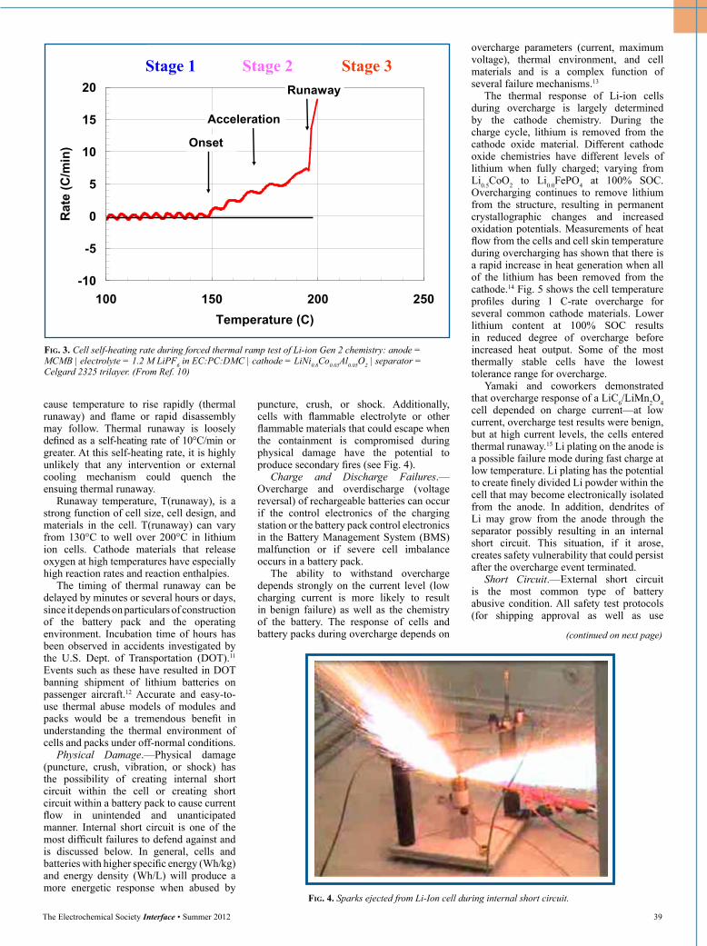
To characterize heat and gas generation that might occur during off-normal conditions, cells and packs are exposed to elevated temperature abusive conditions7 that resemble conditions that might be (rarely) seen in the field. In these tests, response of cells can be characterized as falling into three major temperature regimes.8 These regimes are illustrated in Fig. 3, which shows the temperature rise during thermal ramp of a fully charged lithium ion cell. ARC and Thermal Ramp tests are commonly used to characterize the thermal runaway process.
In Fig. 3, an external source of heat (that simulates an abuse event) is used to raise the temperature of the cell to the Onset Temperature, T(onset). A practical definition of T(onset) is typically a self-heating rate of 0.2°C/min. for thermal ramp experiment. (ARC sensitivity is 0.02°C/min., an order of magnitude more sensitive.) This low heat generation can usually be accommodated and dissipated in the battery packs. Increased reactivity is a consequence of SEI decomposition, exposing the reactive anode to the self-heating reactions involving the electrolyte.9
If this heat is not dissipated, the temperature will continue to rise due to sustained exothermic reactions. The region above the onset temperature is denoted as stage 2 (acceleration), which is characterized by more rapid and accelerating heat release. Stage 2 results from increased electrolyte reduction at the anode due to continuing loss of the SEI and to onset of electrolyte oxidation at the active cathode surface. These reactions depend on the active material chemistries and state of charge. Venting and release of smoke may occur during stage two. Additional heating causes the cell to enter Stage 3 (runaway), in which the high-rate cathode and/or anode reactions
The Electrochemical Society Interface • Summer 2012 39
(continued on next page)
cause temperature to rise rapidly (thermal runaway) and flame or rapid disassembly may follow. Thermal runaway is loosely defined as a self-heating rate of 10°C/min or greater. At this self-heating rate, it is highly unlikely that any intervention or external cooling mechanism could quench the ensuing thermal runaway.
Runaway temperature, T(runaway), is a strong function of cell size, cell design, and materials in the cell. T(runaway) can vary from 130°C to well over 200°C in lithium ion cells. Cathode materials that release oxygen at high temperatures have especially high reaction rates and reaction enthalpies.
The timing of thermal runaway can be delayed by minutes or several hours or days, since it depends on particulars of construction of the battery pack and the operating environment. Incubation time of hours has been observed in accidents investigated by the U.S. Dept. of Transportation (DOT).11 Events such as these have resulted in DOT banning shipment of lithium batteries on passenger aircraft.12 Accurate and easy-to-use thermal abuse models of modules and packs would be a tremendous benefit in understanding the thermal environment of cells and packs under off-normal conditions.
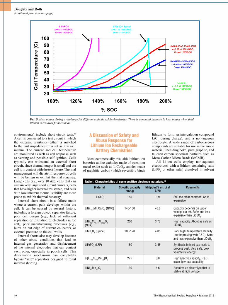
Physical Damage.—Physical damage (puncture, crush, vibration, or shock) has the possibility of creating internal short circuit within the cell or creating short circuit within a battery pack to cause current flow in unintended and unanticipated manner. Internal short circuit is one of the most difficult failures to defend against and is discussed below. In general, cells and batteries with higher specific energy (Wh/ kg) and energy density (Wh/L) will produce a more energetic response when abused by
puncture, crush, or shock. Additionally, cells with flammable electrolyte or other flammable materials that could escape when the containment is compromised during physical damage have the potential to produce secondary fires (see Fig. 4).
Charge and Discharge Failures.—Overcharge and overdischarge (voltage reversal) of rechargeable batteries can occur if the control electronics of the charging station or the battery pack control electronics in the Battery Management System (BMS) malfunction or if severe cell imbalance occurs in a battery pack.
The ability to withstand overcharge depends strongly on the current level (low charging current is more likely to result in benign failure) as well as the chemistry of the battery. The response of cells and battery packs during overcharge depends on
overcharge parameters (current, maximum voltage), thermal environment, and cell materials and is a complex function of several failure mechanisms.13
The thermal response of Li-ion cells during overcharge is largely determined by the cathode chemistry. During the charge cycle, lithium is removed from the cathode oxide material. Different cathode oxide chemistries have different levels of lithium when fully charged; varying from Li0.5CoO2 to Li0.0FePO4 at 100% SOC. Overcharging continues to remove lithium from the structure, resulting in permanent crystallographic changes and increased oxidation potentials. Measurements of heat flow from the cells and cell skin temperature during overcharging has shown that there is a rapid increase in heat generation when all of the lithium has been removed from the cathode.14 Fig. 5 shows the cell temperature profiles during 1 C-rate overcharge for several common cathode materials. Lower lithium content at 100% SOC results in reduced degree of overcharge before increased heat output. Some of the most thermally stable cells have the lowest tolerance range for overcharge.
Yamaki and coworkers demonstrated that overcharge response of a LiC6/LiMn2O4 cell depended on charge current—at low current, overcharge test results were benign, but at high current levels, the cells entered thermal runaway.15 Li plating on the anode is a possible failure mode during fast charge at low temperature. Li plating has the potential to create finely divided Li powder within the cell that may become electronically isolated from the anode. In addition, dendrites of Li may grow from the anode through the separator possibly resulting in an internal short circuit. This situation, if it arose, creates safety vulnerability that could persist after the overcharge event terminated.
Short Circuit.—External short circuit is the most common type of battery abusive condition. All safety test protocols (for shipping approval as well as use
Fig. 4. Sparks ejected from Li-Ion cell during internal short circuit.
Fig. 3. Cell self-heating rate during forced thermal ramp test of Li-ion Gen 2 chemistry: anode = MCMB | electrolyte = 1.2 M LiPF6 in EC:PC:DMC | cathode = LiNi0.8Co0.05Al0.05O2 | separator = Celgard 2325 trilayer. (From Ref. 10)
Figure 3
-10
-5
0
5
10
15
20
100 150 200 250Temperature (C)
Rat
e (C
/min
) Onset
Acceleration
Runaway
Stage 1 Stage 2 Stage 3
40 The Electrochemical Society Interface • Summer 2012
Doughty and Roth (continued from previous page)
environments) include short circuit tests.16 A cell is connected to a test circuit in which the external resistance either is matched to the unit impedance or is set as low as 1 mOhm. The current and cell temperature are monitored as well as cell response such as venting and possible self-ignition. Cells typically can withstand an external short circuit, since thermal output is small and the cell is in contact with the test fixture. Thermal management will dictate if response of cells will be benign or exhibit thermal runaway. Large cells (i.e., over 10 Ah), cells that can sustain very large short circuit currents, cells that have higher internal resistance, and cells with low inherent thermal stability are more prone to exhibit thermal runaway.
Internal short circuit is a failure mode where a current path develops within the cell. It can be caused by several factors, including a foreign object, separator failure, poor cell design (e.g., lack of sufficient separation or insulation of electrodes in the cell), poor manufacturing processes (e.g., burrs on cut edge of current collector), or external pressure on the cell walls.
Internal shorts also may develop because of other abuse conditions that lead to internal gas generation and displacement of the internal electrodes that can contact each other, especially in pouch cells. This deformation mechanism can completely bypass “safe” separators designed to resist internal shorting.
Fig. 5. Heat output during overcharge for different cathode oxide chemistries. There is a marked increase in heat output when final lithium is removed from cathode.
Figure 5
2030405060708090
100
100% 120% 140% 160% 180% 200%
% SOC
Cel
l Tem
pera
ture
(C)
LixNi0.8Co0.15Al0.05O2x=0.36 at 100%SOC;
Onset 125%SOC
LixNi1/3Co1/3Mn1/3O2x~0.48 at 100%SOC;
Onset 170%SOC
LiFePO4x~0 at 100%SOC; Onset 100%SOC
LiMn2O4 Spinelx~0.1 at 100%SOC;
Onset 110%SOC
LixCoO2
x~0.5 at 100%SOCOnset 150%SOC
A Discussion of Safety and Abuse Response for
Lithium Ion Rechargeable Battery Chemistries
Most commercially available lithium ion batteries utilize cathodes made of transition metal oxide such as LiCoO2, anodes made of graphitic carbon (which reversibly binds
lithium to form an intercalation compound LiC6 during charge), and a non-aqueous electrolyte. A wide range of carbonaceous compounds are suitable for use as the anode material, including coke, pure graphite, and tailored carbon spherical particles such as Meso-Carbon Micro Beads (MCMB).
All Li-ion cells employ non-aqueous electrolytes with a lithium-containing salts (LiPF6 or other salts) dissolved in solvent
Table I. Characteristics of some positive electrode materials.19
Material Specific capacity mAh/g
Midpoint V vs. Li at C/20
Comments
LiCoO2 155 3.9 Still the most common. Co is expensive.
LiNi1-x-yMnxCoyO2 (NMC) 140-180 ~3.8 Capacity depends on upper voltage cut off. Safer and less expensive than LiCoO2
LiNi0.8Co0.15Alx0.05O2 (NCA)
200 3.73 High capacity. About as safe as LiCoO2
LiMn2O4 (Spinel) 100-120 4.05 Poor hight temperature stability (but improving with R&D). Safer and less expensive than LiCoO2
LiFePO4 (LFP) 160 3.45 Synthesis in inert gas leads to process cost. Very safe. Low volumetric energy
Li[Li1/9Ni1/3Mn5/9]O2 275 3.8 High specific capacity, R&D scale, low rate capability
LiNi0.5Mn1.5O2 130 4.6 Requires an electrolyte that is stable at high voltage

The Electrochemical Society Interface • Summer 2012 41
mixtures of organic liquids such as ethylene carbonate (EC), propylene carbonate (PC), diethyl carbonate (DEC), or ethyl methyl carbonate (EMC). Separators have the indispensible safety function of physical separation of the electrodes. Because electrolytes and separators will be discussed in other articles, they will only be mentioned as they influence the reaction with electrode materials.
Cathodes in Lithium Ion Batteries.—Choice of cathode has the strongest influence on cell safety.17 Many cathodes are in commercial cells or in development. Table I summarizes performance information on the most common cathodes in use today.
LiCoO2 has been the cathode of choice for the majority of consumer level Li-ion cells produced today. Although it delivers good capacity, LiCoO2 is the most reactive and has poorer thermal stability than the other cathodes. Self-heating of a cell or cell materials at elevated temperature is evidence of chemical instability. The plot of self-heating rate vs. cell temperature provides a good characterization of chemical instability. LiCoO2 decomposes at elevated temperature to produce oxygen that reacts exothermically with organic materials within the cell.18 An ARC plot of self-heating rate vs. cell temperature for a Li-ion 18650 cells fabricated with different cathodes is shown in Fig. 6. Key parameters measured from ARC are onset temperature, maximum self-heating rate, and temperature width of the peak thermal runaway, which gives the enthalpy of the reaction.
LiCoO2 cells are clearly less stable than cells with any of the other mixed-metal oxides shown in Fig. 6 since their onset temperatures are higher and the maximum self-heating rates are lower. However, all these materials are unstable at elevated temperature. Work by Dahn and coworkers demonstrated that most cathode chemistries decompose and evolve oxygen.20 Data on oxygen evolution at elevated temperature have been published for LiCoO2,
21 LiNiO2,22
and LiMn2O4.23 Oxygen production during
high temperature cathode decomposition is correlated with exotherms observed in ARC experiments. The LiFePO4 cathode material does not generate oxygen even when fully decomposed at high temperatures; thus explaining the lowest heating rate during thermal runaway. For these cells, thermal runaway is dominated by anode-electrolyte reactions, which show high-rate decomposition at higher temperatures.
Fig. 7 shows the thermal ramp results for the same cell chemistries discussed above. Although not as sensitive or as quantitative as ARC, the thermal ramp profiles show the same ordering of cell response with reduced oxygen generation. Cathode decomposition onset ranges from 150°C to 250°C. The higher onset temperature of LiMn2O4 and LiFePO4 cells show that they are more resistant to thermal abuse. Moreover,
Fig. 6. Self-heating rate of 18650 full cell measured by ARC. Improved cathode stability results in higher thermal runaway temperature (increased stability) and reduced peak heating rate. (From Ref. 24)
Fig. 7. Onset of self-heating in thermal ramp experiment on Li-ion cells. LiFePO4 olivine cathodes show the greatest reduction in self-heating rate and increased onset temperature for runaway. (From Ref. 24)
Figure 6
EC:PC:DMC\LiPF6
0
100
200
300
400
500
0 100 200 300 400Temperature (C)
Rat
e (C
/min
) Gen2: LiNi0.8Co0.15Al0.05O2:0.93Ah
Gen3: Li1.1(Ni1/3Co1/3Mn1/3)0.9O2: 0.90Ah
LiMn2O4 : 0.65Ah
LiFePO4: 1.18Ah
LiCoO2: 1.20Ah
Figure 7
0102030405060708090
100
0 50 100 150 200 250 300Temperature (C)
Rat
e (C
/min
)
26650 2.1Ah
LiFePO418650 0.9Ah
Li1.1(Ni1/3Co1/3Mn1/3)0.9O2
18650 0.9AhLiNi0.8Co0.15Al0.05O2
26650 2.6Ah
LiMn2O4
the reduced peak of self-heating rate of LiFePO4-based cells makes them the safest cells Li-ion batteries on the market today.
Much research is being performed to develop advanced cathode materials that will allow increased energy density, rate capability, and cycle life at low cost. The DOE, through the Vehicles Technology Program, has supported development of several promising chemistries.25 Examples of these developing materials include substituted spinels (LiMn1.8Li0.1Ni0.1O3.8F0.2) and high voltage cathodes with two-component integrated structures
(xLi2M’O3•(1-x)LiMO2 and xLi2M’O3•(1-x)LiM2O4 where is M’ is predominately Mn and M is Mn, Ni, or Co).26 Other materials are being developed using new approaches such as core-shell, concentration-gradient materials, and nanocoatings.27 For example, ARC tests were performed at Sandia on several 18650 cells using AlF3-coated NMC cathodes provided by Argonne National Laboratory.28
Fig. 8 shows the ARC thermal response profiles for uncoated and AlF3-coated cathodes in 18650 cells. All of the coated electrodes showed reduced heating rates
(continued on next page)
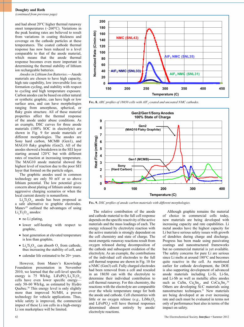
Fig. 8. ARC profiles of 18650 cells with AlF3-coated and uncoated NMC cathodes.
Fig. 9. DSC profiles of anode carbon materials with different morphologies.
Figure 8
0
20
40
60
80
100
120
140
160
180
200
150 200 250 300 350 400 450
Nor
mal
ized
Rat
e (C
/min
-Ah)
Temperature (C)
NMC (SNL43)
AlF3 NMC (SNL35)
AlF3 NMC (SNL33)AlF3 NMC (SNL31)
Figure 9
0
1
2
3
4
5
6
7
8
9
0 100 200 300 400
Hea
t Flo
w (m
W/m
g)
Temperature (C)
Gen2/Gen1/Sony Anodes 100% State of Charge
Gen1 (MCMB)
Sony (Hard Carbon)
Gen2 (MAG10 Flaky Graphite)
The relative contribution of the anode and cathode material to the full cell response depends on the specific reactivity of the active materials and the mass loadings of each. The energy released by electrolyte reaction with the active materials is strongly dependent on the cell chemistry and state of charge. The most energetic runaway reactions result from oxygen released during decomposition of the cathode and subsequent oxidation of the electrolyte. As an example, the contributions of the individual cell electrodes to the full cell thermal response are shown in Fig. 10 for a NMC (Gen3) cell. Fully charged electrodes had been removed from a cell and resealed in an 18650 can with the electrolyte to determine their individual contribution to cell thermal runaway. For this chemistry, the reactions with the electrolyte are comparable over the whole temperature range for both the anode and cathode. Cell chemistries with little or no oxygen release (e.g., LiMn2O4 and LiFePO4) will have thermal responses determined almost entirely by anode/electrolyte reactions.
Although graphite remains the material of choice in commercial cells today, new materials are being developed with increasing capacity and rate capabilities. Li metal anodes have the highest capacity for Li but have serious safety issues with growth of dendrites during charge and discharge. Progress has been made using passivating coatings and nanostructured frameworks but no commercial material is yet available. The safety concerns for pure Li are serious since Li melts at around 180°C and becomes quite reactive in the cell. As mentioned earlier for cathode development, the DOE is also supporting development of advanced anode materials including Li-Si, Li-Sn, and Li-Sb as well as metallic alloy anodes such as CuSn, Cu6Sn6, and CoCu5Sn5.
26 Others are developing Si:C materials using nanostructure techniques.31 New materials are being developed at an ever increasing rate and each must be evaluated in terms not only of performance bust also in terms of the impact on safety.
42 The Electrochemical Society Interface • Summer 2012
Doughty and Roth (continued from previous page)
and had about 20°C higher thermal runaway onset temperatures (~260°C). Variations in the peak heating rates are believed to result from variations in coating thickness and coverage on the cathode particles at these temperatures. The coated cathode thermal response has now been reduced to a level comparable to that of the anode material, which means that the anode thermal response becomes even more important in determining the thermal stability of lithium ion rechargeable batteries.
Anodes in Lithium Ion Batteries.—Anode materials are chosen to have high capacity, high rate capability, low irreversible loss on formation cycling, and stability with respect to cycling and high temperature exposure. Carbon anodes can be based on either natural or synthetic graphite, can have high or low surface area, and can have morphologies ranging from amorphous, spherical, or flaky grain structure. All of these material properties affect the thermal response of the anode under abuse conditions. As an example, DSC curves for three anode materials (100% SOC in electrolyte) are shown in Fig. 9 for anode materials of different morphologies. The anodes are Sony hard carbon, MCMB (Gen1), and MAG10 flaky graphite (Gen2). All of the anodes showed a breakdown in the SEI layer starting around 120°C but with different rates of reaction at increasing temperature. The MAG10 anode material showed the highest level of reaction due to the poor SEI layer that formed on the particle edges.
The graphitic anodes used in common technology are only 50 mV or so above lithium potential. The low potential gives concern about plating of lithium under many aggressive charging scenarios or when the local current density is nonuniform.
Li4Ti5O12 anode has been proposed as a safe alternative to graphite electrodes. Manev29 outlined the advantages of using Li4Ti5O12 anodes:
• no Li plating,• lower self-heating with respect to
graphite,• heat generation at elevated temperature
is less than graphite,•Li4Ti5O12 can absorb O2 from cathode,
thus increasing the stability of cell, and• calendar life estimated to be 20+ years.
However, from Manev’s Knowledge Foundation presentation in November 2010, we learned that the cell-level specific energy is 75 Wh/kg. LiFePO4/Li4Ti5O12 cells have even lower specific energy—only 50- 60 Wh/kg, as estimated by Hydro Quebec.30 This energy level is only slightly more than improved Ni/MH, a proven technology for vehicle applications. Thus, while safety is improved, the commercial impact of these Li ion cells in a high-energy Li ion marketplace will be limited.

Fig. 10. ARC profiles of anode and cathode electrodes in electrolyte compared to full cell response.
Fig. 11. ARC profiles of Sanyo 18650 cells at increasing states of charge.
Figure 10
MCMB/Li1.1(Ni1/3Co1/3Mn1/3O2)0.9
EC:PC:DMC/1.2MLiPF6
0
5
10
15
20
25
30
35
40
45
50
50 100 150 200 250 300 350 400 450Temperature (C)
Rat
e (C
/min
)
Full Cell
Anode Cathode
Electrolyte
Figure 11
0100200300400500600700800900
1000
0 100 200 300 400 500
Rat
e (C
/min
)
Temperature (C)
Sanyo Cells
SanyoCell #809: 4.3VSanyoCell: 4.2VSanyoCell #778: 4.0VSanyoCell #772: 3.8V
3.8V
4.0V
4.2V
4.3V
Effect of SOC on Thermal Stability.—State of Charge is one of the most important factors in determining response of a cell or pack to abusive events. That is why shipping regulations require that lithium ion rechargeable batteries be at a low SOC during shipment. While not many careful studies have been published on effect of SOC and age, a Sandia National Laboratories publication32 provides quanti-tative comparison for two Li-ion battery chemistries (LiCoO2 and LiNi0.8Co0.2O2). The onset of self-generated heating decreased to lower temperatures with increasing SOC and the magnitude of the heating rate increased more rapidly with increasing temperature. The higher states of charge result in increased levels of lithiation of the anode that increases electrolyte reactions. These onset reactions exhibit a much lower
heating rate than seen during full thermal runaway, as was shown in Fig. 6.
The peak thermal response of a cell also increases rapidly with degree of charge. Fig. 11 shows the ARC profiles for Sanyo (LiCoO2) cells with increasing states of charge from 3.8V to 4.3V. The onset of the high-rate (Stage 3) reactions did not change significantly with state of charge but the peak heating rates and the enthalpy of the high-rate reactions increased markedly. During overcharge, excessive lithium is extracted from the cathode and a corresponding excessive insertion and/or plating of lithium may occur at the anode. These conditions make both electrodes less thermally stable. This peak response depends strongly on the type of cathode material used and the anode/cathode capacity balance.
Finally, the magnitude of response of a cell to internal short circuit will be influenced by SOC. When a cell is at 100% SOC, internal short circuit often results in thermal runaway of cell. However, when cell is at 80% SOC the maximum temperature may be reduced to 200°C. At 70% SOC, internal short circuit can be well tolerated.33
Conclusion
Safety response of Li ion batteries is increasingly recognized as a critical performance requirement for commercial adoption of this chemistry, especially in large scale vehicular applications. The development of increasingly safe battery systems requires continued improvements in cell thermal stability as well as new pack and vehicle designs with rigorous and redundant safety controls.
There are many advanced materials being developed and characterized in industry, universities, and national laboratories for Li ion batteries. These materials are often developed primarily for improved performance such as energy density, specific energy, power capability, low temperature response, cycle lifetime, and cost. Safety is often a property determined after the development phase. Safety and thermal stability should become a prime consideration in the initial development and material selection process. There is certainly no need for a “safe” battery that does not perform but also there is no need for a high performance battery that is unsafe.
Acknowledgments
The data presented here was developed over several years with the support of the DOE ATD program which was part of FreedomCAR and Fuel Partnerships (now the ABR program which is part of U.S. Drive).
Sandia National Laboratories is a multi-program laboratory managed and operated by Sandia Corporation, a wholly owned subsidiary of Lockheed Martin Corporation, for the U.S. Department of Energy’s National Nuclear Security Administration under contract DE-AC04-94AL85000.
About the Authors
Daniel H. DougHty has been involved with battery R&D, testing, and evaluation since 1992. During his 35 year career in science and technology, he spent 27 years at Sandia National Laboratories, the last 14 years of which he managed the battery R&D group that was responsible for battery safety and abuse tolerance testing. After leaving Sandia in December 2006, he spent over two years as Vice-President for Product Safety for SION Power Corp., a company in Tucson, Arizona focused on commercializing Li-
The Electrochemical Society Interface • Summer 2012 43
(continued on next page)

sulfur rechargeable batteries. Dr. Doughty is President and founder of Battery Safety Consulting Inc., a company dedicated to providing expert and independent consulting services for a wide range of battery safety issues. He was the Chair of the Society of Automotive Engineers Committee which revised and updated the SAE Recommend Test Procedure J2464, “Electric and Hybrid Electric Vehicle Rechargeable Energy Storage System (RESS) Safety and Abuse Testing,” published November 2009. He may be reached at [email protected].
e. Peter rotH was the Project Leader for the Battery Safety R&D Program at Sandia National Labs until his retirement in 2010 after 31 years at Sandia in the area of material thermal properties. He has been involved with the Battery R&D program since 1998 and helped establish the battery thermal abuse laboratory at Sandia during that time. Dr. Roth continues to serve as a consultant to the department and outside groups. Prior to joining Sandia in 1978, he earned his BS degree in physics at the University of Washington in 1974 and completed his MS and PhD in condensed matter physics at the University of Illinois, Urbana-Champaign in 1978. He may be reached at [email protected].
References 1. B. M. Barnett, E. P. Roth, K. E.
Thomas-Alyea, and D. H. Doughty, “Abuse Tolerance versus Field Failure: Two Different Issues for Lithium-Ion Safety,” presented at the International Meeting on Lithium Batteries, June 2006.
2. J. Dahn and G. M. Erlich, “Lithium Ion Batteries,” p. 26, Linden’s Handbook of Batteries, 4th edition, T. B. Reddy, Ed., McGraw Hill, 2011.
3. J. S. Gnanaraj, E. Zinigrad, L. Asraf, H. E. Gottlieb, M. Sprecher, M. Schmidt, W. Geissler, and D. Aurbach, J. Electrochem. Soc., 150, A1533 (2003).
4. http://www.thermalhazardtechnology.com/index.htm
5. E. P. Roth, C. C. Crafts, D. H. Doughty, and J. McBreen, Sandia Report SAND2004-0584, March 2004.
6. S. C. Levy and P. Bro, Battery Hazards and Accident Prevention, Plenum Press, 1994.
7. E. P. Roth and D. H. Doughty, J. Power Sources, 128, 308 (2004).
8. E. P. Roth, ECS Transactions, 11(19), 19 (2008).
9. D. D. MacNeil, D. Larcher, and J. R. Dahn, J. Electrochem. Soc., 146, 3596 (1999).
10. D. H. Doughty, “Li-ion Battery Abuse Tolerance Testing—An Overview,” Proc. AABC, Honolulu, HI, June 2005.
11. M. D. Farrington, J. Power Sources, 96, 260 (2001).
12. http://www.usatoday.com/tech/news/techpolicy/2007-03-05-batteries-planes_N.htm
13. D. Belov and Mo-Hua Yang, J. Solid State Electrochem., 12, 885 (2008).
14. E. P. Roth and C. Orendorff, presented at Advanced Automotive Battery and EC Capacitor Conference, Long Beach, California, June 8-12, 2009.
15. T. Yoshida, K. Kitoh, S. Ohtsubo, W. Shionoya, H. Katsukawa, and J-I. Yamaki, Electrochem. Solid-State Lett., 10, A60 (2007).
16. D. H. Doughty, Proc. SAE 2010 World Congress, April 13-15, 2010, DOI: 10.4271/2010-01-1077.
17. H. Maleki, G. Deng, A. Anani, and J. Howard, J. Electrochem. Soc., 146, 3224 (1999).
18. H. Arai, M. Tsuda, K. Saito, M. Hayashi, and Y. Sakurai, J. Electrochem. Soc., 149, A401 (2002).
Doughty and Roth (continued from previous page) 19. J. Dahn and G. M. Erlich, “Lithium
Ion Batteries,” p 26, Table 26.3, in Linden’s Handbook of Batteries, 4th edition, T. B. Reddy, Ed., McGraw Hill, 2011.
20. J. R. Dahn, et al., Solid State Ionics, 69, 265 (1994).
21. D. D. MacNeil and J. R. Dahn, J. Electrochem. Soc., 148, A1205 (2001).
22. H. Arai, M. Tsuda, K. Saito, M. Hayashi, and Y. Sakurai, J. Electrochem. Soc., 149, A401 (2002).
23. D. D. MacNeil and J. R. Dahn, J. Electrochem. Soc., 148, A1211 (2001).
24. E. P. Roth, presented at 43rd Power Sources Conf., Philadelphia, PA, 2008.
25. DOE Energy Storage Research and Development Program http://www1.eere.energy.gov/vehiclesandfuels
26. D. Howell, T. Duong, H. B. Deppe, and I. Weinstock, Material Matters, 3.4, 100 (2008).
27. Z. Chen, D-J. Lee, Y-K. Sun, and K. Amine, MRS Bulletin, 36, 498 (2011).
28. C. Orendorff, Advanced Automotive Battery Conference Proceedings, Pasadena, CA, January 25, 2011.
29. V. Manev, “Large Format Li4Ti5O12 Li-ion Batteries – Performance and Applications.” Li Mobile Power, Boston, MA, Nov. 4-5, 2010.
30. K. Zaghib, “Olivine-Polymer Ionic Liquid-Lithium for High Energy Batteries for Green Transportation,” Pacific Power Source Symposium 2011, Waikoloa, HI, January 10-14, 2011.
31 U. Kasavajjulaa, C. Wang, and A. J. Appleby, J. Power Sources, 163, 1003, (2007).
32. E. P. Roth, C. C. Crafts, and D. H. Doughty, SAND2004-0584 “Thermal Abuse Performance of 18650 Li-ion Cells,” April 2004.
33. Z. (John) Zhang, “Perspectives on Safety and Life for Li-Ion Application in Electric Drive Vehicles (EDV),” Pacific Power Source Symposium 2011, Waikoloa, Hawaii, January 10-15, 2011.
44 The Electrochemical Society Interface • Summer 2012