redbook ibm (svc-2145) best practices
TRANSCRIPT

ibm.com/redbooks
Front cover
SAN Volume Controller: Best Practices and Performance Guidelines
Jon TateDeon George
Thorsten HossRonda Hruby
Ian MacQuarrieBarry Mellish
Peter Mescher
Read about best practices learned from the field
Learn about SVC performance advantages
Fine-tune your SVC


International Technical Support Organization
SAN Volume Controller: Best Practices and Performance Guidelines
March 2008
SG24-7521-00

© Copyright International Business Machines Corporation 2008. All rights reserved.Note to U.S. Government Users Restricted Rights -- Use, duplication or disclosure restricted by GSA ADP ScheduleContract with IBM Corp.
First Edition (March 2008)
This edition applies to Version 4.2 of the IBM System Storage SAN Volume Controller.
Note: Before using this information and the product it supports, read the information in “Notices” on page xi.
Contents
Notices . . . . . . . . . . . . . . . . . . . . . . . . . . . . . . . . . . . . . . . . . . . . . . . . . . . . . . . . . . . . . . . . . xiTrademarks . . . . . . . . . . . . . . . . . . . . . . . . . . . . . . . . . . . . . . . . . . . . . . . . . . . . . . . . . . . . . . xii
Preface . . . . . . . . . . . . . . . . . . . . . . . . . . . . . . . . . . . . . . . . . . . . . . . . . . . . . . . . . . . . . . . . xiiiThe team that wrote this book . . . . . . . . . . . . . . . . . . . . . . . . . . . . . . . . . . . . . . . . . . . . . . . xiiiBecome a published author . . . . . . . . . . . . . . . . . . . . . . . . . . . . . . . . . . . . . . . . . . . . . . . . . .xvComments welcome. . . . . . . . . . . . . . . . . . . . . . . . . . . . . . . . . . . . . . . . . . . . . . . . . . . . . . . .xv
Chapter 1. SAN fabric . . . . . . . . . . . . . . . . . . . . . . . . . . . . . . . . . . . . . . . . . . . . . . . . . . . . . 11.1 SVC SAN topology . . . . . . . . . . . . . . . . . . . . . . . . . . . . . . . . . . . . . . . . . . . . . . . . . . . . . 2
1.1.1 Redundancy . . . . . . . . . . . . . . . . . . . . . . . . . . . . . . . . . . . . . . . . . . . . . . . . . . . . . . 21.1.2 Topology basics . . . . . . . . . . . . . . . . . . . . . . . . . . . . . . . . . . . . . . . . . . . . . . . . . . . 21.1.3 ISL oversubscription . . . . . . . . . . . . . . . . . . . . . . . . . . . . . . . . . . . . . . . . . . . . . . . . 31.1.4 IBM 2109-M12/Brocade 12000 in an SVC environment . . . . . . . . . . . . . . . . . . . . . 41.1.5 Switch port layout for large edge switches . . . . . . . . . . . . . . . . . . . . . . . . . . . . . . . 41.1.6 Switch port layout and hardware selection for director-class core switches . . . . . . 51.1.7 Single switch SVC SANs. . . . . . . . . . . . . . . . . . . . . . . . . . . . . . . . . . . . . . . . . . . . . 51.1.8 Basic core-edge topology . . . . . . . . . . . . . . . . . . . . . . . . . . . . . . . . . . . . . . . . . . . . 51.1.9 Four-SAN core-edge topology . . . . . . . . . . . . . . . . . . . . . . . . . . . . . . . . . . . . . . . . 61.1.10 Cisco VSANs . . . . . . . . . . . . . . . . . . . . . . . . . . . . . . . . . . . . . . . . . . . . . . . . . . . . 71.1.11 Common topology issues . . . . . . . . . . . . . . . . . . . . . . . . . . . . . . . . . . . . . . . . . . . 8
1.2 Tape and disk on your SAN . . . . . . . . . . . . . . . . . . . . . . . . . . . . . . . . . . . . . . . . . . . . . 101.3 Switch interoperability . . . . . . . . . . . . . . . . . . . . . . . . . . . . . . . . . . . . . . . . . . . . . . . . . . 101.4 Distance extension for mirroring . . . . . . . . . . . . . . . . . . . . . . . . . . . . . . . . . . . . . . . . . . 11
1.4.1 Optical multiplexors. . . . . . . . . . . . . . . . . . . . . . . . . . . . . . . . . . . . . . . . . . . . . . . . 111.4.2 Long-distance SFPs/XFPs . . . . . . . . . . . . . . . . . . . . . . . . . . . . . . . . . . . . . . . . . . 111.4.3 Fibre Channel: IP Conversion. . . . . . . . . . . . . . . . . . . . . . . . . . . . . . . . . . . . . . . . 11
1.5 Zoning . . . . . . . . . . . . . . . . . . . . . . . . . . . . . . . . . . . . . . . . . . . . . . . . . . . . . . . . . . . . . . 121.5.1 Type of zoning . . . . . . . . . . . . . . . . . . . . . . . . . . . . . . . . . . . . . . . . . . . . . . . . . . . 121.5.2 Pre-zoning tips and shortcuts . . . . . . . . . . . . . . . . . . . . . . . . . . . . . . . . . . . . . . . . 141.5.3 SVC cluster zone . . . . . . . . . . . . . . . . . . . . . . . . . . . . . . . . . . . . . . . . . . . . . . . . . 141.5.4 SVC: Storage zones . . . . . . . . . . . . . . . . . . . . . . . . . . . . . . . . . . . . . . . . . . . . . . . 141.5.5 SVC: Host zones. . . . . . . . . . . . . . . . . . . . . . . . . . . . . . . . . . . . . . . . . . . . . . . . . . 141.5.6 Sample standard SVC zoning configuration . . . . . . . . . . . . . . . . . . . . . . . . . . . . . 161.5.7 Zoning with multiple SVC clusters. . . . . . . . . . . . . . . . . . . . . . . . . . . . . . . . . . . . . 201.5.8 Split controller configurations . . . . . . . . . . . . . . . . . . . . . . . . . . . . . . . . . . . . . . . . 20
1.6 Switch Domain IDs . . . . . . . . . . . . . . . . . . . . . . . . . . . . . . . . . . . . . . . . . . . . . . . . . . . . 201.7 TotalStorage Productivity Center for Fabric . . . . . . . . . . . . . . . . . . . . . . . . . . . . . . . . . 20
Chapter 2. SAN Volume Controller cluster . . . . . . . . . . . . . . . . . . . . . . . . . . . . . . . . . . . 212.1 Advantages of virtualization . . . . . . . . . . . . . . . . . . . . . . . . . . . . . . . . . . . . . . . . . . . . . 22
2.1.1 How does the SVC fit into your environment . . . . . . . . . . . . . . . . . . . . . . . . . . . . 222.2 Scalability of SVC clusters . . . . . . . . . . . . . . . . . . . . . . . . . . . . . . . . . . . . . . . . . . . . . . 22
2.2.1 Advantage of multi cluster as opposed to single cluster . . . . . . . . . . . . . . . . . . . . 232.2.2 Performance expectations by adding an SVC . . . . . . . . . . . . . . . . . . . . . . . . . . . 232.2.3 Growing or splitting SVC clusters . . . . . . . . . . . . . . . . . . . . . . . . . . . . . . . . . . . . . 24
2.3 SVC cache improves subsystem performance . . . . . . . . . . . . . . . . . . . . . . . . . . . . . . . 262.3.1 Cache destage operations . . . . . . . . . . . . . . . . . . . . . . . . . . . . . . . . . . . . . . . . . . 29
© Copyright IBM Corp. 2008. All rights reserved. iii
2.4 Cluster upgrade. . . . . . . . . . . . . . . . . . . . . . . . . . . . . . . . . . . . . . . . . . . . . . . . . . . . . . . 30
Chapter 3. Master console . . . . . . . . . . . . . . . . . . . . . . . . . . . . . . . . . . . . . . . . . . . . . . . . 333.1 Managing the master console . . . . . . . . . . . . . . . . . . . . . . . . . . . . . . . . . . . . . . . . . . . . 34
3.1.1 Managing a single master console . . . . . . . . . . . . . . . . . . . . . . . . . . . . . . . . . . . . 343.1.2 Managing multiple master consoles . . . . . . . . . . . . . . . . . . . . . . . . . . . . . . . . . . . 393.1.3 Administration roles . . . . . . . . . . . . . . . . . . . . . . . . . . . . . . . . . . . . . . . . . . . . . . . 403.1.4 Audit logging . . . . . . . . . . . . . . . . . . . . . . . . . . . . . . . . . . . . . . . . . . . . . . . . . . . . . 463.1.5 Managing IDs and passwords. . . . . . . . . . . . . . . . . . . . . . . . . . . . . . . . . . . . . . . . 503.1.6 Saving the SVC configuration . . . . . . . . . . . . . . . . . . . . . . . . . . . . . . . . . . . . . . . . 523.1.7 Restoring the SVC cluster configuration . . . . . . . . . . . . . . . . . . . . . . . . . . . . . . . . 53
Chapter 4. I/O Groups and nodes . . . . . . . . . . . . . . . . . . . . . . . . . . . . . . . . . . . . . . . . . . 554.1 Determining I/O Groups . . . . . . . . . . . . . . . . . . . . . . . . . . . . . . . . . . . . . . . . . . . . . . . . 564.2 Node shutdown and node failure . . . . . . . . . . . . . . . . . . . . . . . . . . . . . . . . . . . . . . . . . 56
4.2.1 Impact when running single node I/O Groups. . . . . . . . . . . . . . . . . . . . . . . . . . . . 574.3 Adding or upgrading SVC node hardware . . . . . . . . . . . . . . . . . . . . . . . . . . . . . . . . . . 58
Chapter 5. Storage controller. . . . . . . . . . . . . . . . . . . . . . . . . . . . . . . . . . . . . . . . . . . . . . 615.1 Controller affinity and preferred path. . . . . . . . . . . . . . . . . . . . . . . . . . . . . . . . . . . . . . . 62
5.1.1 ADT for DS4000 . . . . . . . . . . . . . . . . . . . . . . . . . . . . . . . . . . . . . . . . . . . . . . . . . . 625.1.2 Ensuring path balance prior to MDisk discovery . . . . . . . . . . . . . . . . . . . . . . . . . . 63
5.2 Pathing considerations for EMC Symmetrix/DMX and HDS . . . . . . . . . . . . . . . . . . . . . 635.3 LUN ID to MDisk translation . . . . . . . . . . . . . . . . . . . . . . . . . . . . . . . . . . . . . . . . . . . . . 63
5.3.1 ESS. . . . . . . . . . . . . . . . . . . . . . . . . . . . . . . . . . . . . . . . . . . . . . . . . . . . . . . . . . . . 635.3.2 DS6000 and DS8000 . . . . . . . . . . . . . . . . . . . . . . . . . . . . . . . . . . . . . . . . . . . . . . 64
5.4 MDisk to VDisk mapping . . . . . . . . . . . . . . . . . . . . . . . . . . . . . . . . . . . . . . . . . . . . . . . . 655.5 Mapping physical LBAs to Extents . . . . . . . . . . . . . . . . . . . . . . . . . . . . . . . . . . . . . . . . 665.6 Media error logging . . . . . . . . . . . . . . . . . . . . . . . . . . . . . . . . . . . . . . . . . . . . . . . . . . . . 66
5.6.1 Host encountered media errors. . . . . . . . . . . . . . . . . . . . . . . . . . . . . . . . . . . . . . . 665.6.2 SVC-encountered media errors . . . . . . . . . . . . . . . . . . . . . . . . . . . . . . . . . . . . . . 67
5.7 Selecting array and cache parameters . . . . . . . . . . . . . . . . . . . . . . . . . . . . . . . . . . . . . 685.7.1 DS4000 array width . . . . . . . . . . . . . . . . . . . . . . . . . . . . . . . . . . . . . . . . . . . . . . . 685.7.2 Segment size . . . . . . . . . . . . . . . . . . . . . . . . . . . . . . . . . . . . . . . . . . . . . . . . . . . . 695.7.3 DS8000 . . . . . . . . . . . . . . . . . . . . . . . . . . . . . . . . . . . . . . . . . . . . . . . . . . . . . . . . . 70
5.8 Considerations for controller configuration . . . . . . . . . . . . . . . . . . . . . . . . . . . . . . . . . . 705.8.1 Balancing workload across DS4000 controllers . . . . . . . . . . . . . . . . . . . . . . . . . . 705.8.2 Balancing workload across DS8000 controllers . . . . . . . . . . . . . . . . . . . . . . . . . . 715.8.3 DS8000 ranks/extent pools . . . . . . . . . . . . . . . . . . . . . . . . . . . . . . . . . . . . . . . . . . 735.8.4 Mixing array sizes within an MDG. . . . . . . . . . . . . . . . . . . . . . . . . . . . . . . . . . . . . 745.8.5 Determining the number of controller ports for ESS/DS8000 . . . . . . . . . . . . . . . . 745.8.6 Determining the number of controller ports for DS4000 . . . . . . . . . . . . . . . . . . . . 74
5.9 LUN masking. . . . . . . . . . . . . . . . . . . . . . . . . . . . . . . . . . . . . . . . . . . . . . . . . . . . . . . . . 755.10 WWPN to physical port translation . . . . . . . . . . . . . . . . . . . . . . . . . . . . . . . . . . . . . . . 775.11 Using TPC to identify storage controller boundaries . . . . . . . . . . . . . . . . . . . . . . . . . . 785.12 Using TPC to measure storage controller performance . . . . . . . . . . . . . . . . . . . . . . . 79
5.12.1 Approximations . . . . . . . . . . . . . . . . . . . . . . . . . . . . . . . . . . . . . . . . . . . . . . . . . . 805.12.2 Establish a performance baseline. . . . . . . . . . . . . . . . . . . . . . . . . . . . . . . . . . . . 815.12.3 Performance metric guidelines . . . . . . . . . . . . . . . . . . . . . . . . . . . . . . . . . . . . . . 815.12.4 Storage controller back end . . . . . . . . . . . . . . . . . . . . . . . . . . . . . . . . . . . . . . . . 82
iv SAN Volume Controller: Best Practices and Performance Guidelines

Chapter 6. MDisks . . . . . . . . . . . . . . . . . . . . . . . . . . . . . . . . . . . . . . . . . . . . . . . . . . . . . . . 856.1 Back-end queue depth . . . . . . . . . . . . . . . . . . . . . . . . . . . . . . . . . . . . . . . . . . . . . . . . . 866.2 MDisk transfer size . . . . . . . . . . . . . . . . . . . . . . . . . . . . . . . . . . . . . . . . . . . . . . . . . . . . 86
6.2.1 Host I/O. . . . . . . . . . . . . . . . . . . . . . . . . . . . . . . . . . . . . . . . . . . . . . . . . . . . . . . . . 866.2.2 FlashCopy I/O . . . . . . . . . . . . . . . . . . . . . . . . . . . . . . . . . . . . . . . . . . . . . . . . . . . . 876.2.3 Coalescing writes . . . . . . . . . . . . . . . . . . . . . . . . . . . . . . . . . . . . . . . . . . . . . . . . . 87
6.3 Selecting LUN attributes for MDisks . . . . . . . . . . . . . . . . . . . . . . . . . . . . . . . . . . . . . . . 876.4 Tiered storage . . . . . . . . . . . . . . . . . . . . . . . . . . . . . . . . . . . . . . . . . . . . . . . . . . . . . . . . 886.5 Adding MDisks to existing MDGs . . . . . . . . . . . . . . . . . . . . . . . . . . . . . . . . . . . . . . . . . 88
6.5.1 Adding MDisks for capacity. . . . . . . . . . . . . . . . . . . . . . . . . . . . . . . . . . . . . . . . . . 896.5.2 Checking access to new MDisks. . . . . . . . . . . . . . . . . . . . . . . . . . . . . . . . . . . . . . 896.5.3 Persistent reserve . . . . . . . . . . . . . . . . . . . . . . . . . . . . . . . . . . . . . . . . . . . . . . . . . 89
6.6 Removing MDisks from existing MDGs. . . . . . . . . . . . . . . . . . . . . . . . . . . . . . . . . . . . . 906.7 Remapping managed MDisks . . . . . . . . . . . . . . . . . . . . . . . . . . . . . . . . . . . . . . . . . . . . 926.8 Controlling extent allocation order for VDisk creation . . . . . . . . . . . . . . . . . . . . . . . . . . 93
Chapter 7. Managed disk groups. . . . . . . . . . . . . . . . . . . . . . . . . . . . . . . . . . . . . . . . . . . 977.1 Availability considerations for planning MDGs . . . . . . . . . . . . . . . . . . . . . . . . . . . . . . . 98
7.1.1 Performance consideration . . . . . . . . . . . . . . . . . . . . . . . . . . . . . . . . . . . . . . . . . . 997.1.2 Selecting the MDisk Group . . . . . . . . . . . . . . . . . . . . . . . . . . . . . . . . . . . . . . . . . 100
7.2 Selecting number of LUNs per array. . . . . . . . . . . . . . . . . . . . . . . . . . . . . . . . . . . . . . 1027.2.1 Performance comparison of one compared to two LUNs per array . . . . . . . . . . 102
7.3 Selecting the number of arrays per MDG . . . . . . . . . . . . . . . . . . . . . . . . . . . . . . . . . . 1057.4 Striping compared to sequential type . . . . . . . . . . . . . . . . . . . . . . . . . . . . . . . . . . . . . 1117.5 Selecting storage controllers . . . . . . . . . . . . . . . . . . . . . . . . . . . . . . . . . . . . . . . . . . . . 112
Chapter 8. VDisks . . . . . . . . . . . . . . . . . . . . . . . . . . . . . . . . . . . . . . . . . . . . . . . . . . . . . . 1138.1 Creating VDisks . . . . . . . . . . . . . . . . . . . . . . . . . . . . . . . . . . . . . . . . . . . . . . . . . . . . . 114
8.1.1 Selecting the MDisk Group . . . . . . . . . . . . . . . . . . . . . . . . . . . . . . . . . . . . . . . . . 1168.1.2 Changing the preferred node within an I/O Group . . . . . . . . . . . . . . . . . . . . . . . 1168.1.3 Moving a VDisk to another I/O Group . . . . . . . . . . . . . . . . . . . . . . . . . . . . . . . . . 117
8.2 VDisk migration . . . . . . . . . . . . . . . . . . . . . . . . . . . . . . . . . . . . . . . . . . . . . . . . . . . . . . 1198.2.1 Migrating across MDGs. . . . . . . . . . . . . . . . . . . . . . . . . . . . . . . . . . . . . . . . . . . . 1198.2.2 Image type to striped type migration . . . . . . . . . . . . . . . . . . . . . . . . . . . . . . . . . . 1198.2.3 Migrating to image type VDisk . . . . . . . . . . . . . . . . . . . . . . . . . . . . . . . . . . . . . . 1198.2.4 Preferred paths to a VDisk . . . . . . . . . . . . . . . . . . . . . . . . . . . . . . . . . . . . . . . . . 1218.2.5 Governing of VDisks . . . . . . . . . . . . . . . . . . . . . . . . . . . . . . . . . . . . . . . . . . . . . . 122
8.3 Cache-disabled VDisks . . . . . . . . . . . . . . . . . . . . . . . . . . . . . . . . . . . . . . . . . . . . . . . . 1258.3.1 Using underlying controller remote copy with SVC cache-disabled VDisks . . . . 1258.3.2 Using underlying controller PiT copy with SVC cache-disabled VDisks . . . . . . . 1268.3.3 Changing cache mode of VDisks . . . . . . . . . . . . . . . . . . . . . . . . . . . . . . . . . . . . 127
8.4 VDisk performance . . . . . . . . . . . . . . . . . . . . . . . . . . . . . . . . . . . . . . . . . . . . . . . . . . . 1298.4.1 VDisk performance . . . . . . . . . . . . . . . . . . . . . . . . . . . . . . . . . . . . . . . . . . . . . . . 132
8.5 The effect of load on storage controllers . . . . . . . . . . . . . . . . . . . . . . . . . . . . . . . . . . . 139
Chapter 9. Copy services . . . . . . . . . . . . . . . . . . . . . . . . . . . . . . . . . . . . . . . . . . . . . . . . 1439.1 SAN Volume Controller Advanced Copy Services functions. . . . . . . . . . . . . . . . . . . . 144
9.1.1 SVC copy service functions . . . . . . . . . . . . . . . . . . . . . . . . . . . . . . . . . . . . . . . . 1449.1.2 Using both Metro Mirror and Global Mirror between two clusters . . . . . . . . . . . . 1449.1.3 Performing three-way copy service functions . . . . . . . . . . . . . . . . . . . . . . . . . . . 1449.1.4 Using native controller Advanced Copy Services functions . . . . . . . . . . . . . . . . 145
9.2 Copy service limits . . . . . . . . . . . . . . . . . . . . . . . . . . . . . . . . . . . . . . . . . . . . . . . . . . . 1469.3 Setting up FlashCopy copy services . . . . . . . . . . . . . . . . . . . . . . . . . . . . . . . . . . . . . . 147
9.3.1 Steps to making a FlashCopy VDisk with application data integrity . . . . . . . . . . 148
Contents v

9.3.2 Making multiple related FlashCopy VDisks with data integrity . . . . . . . . . . . . . . 1519.3.3 Creating multiple identical copies of a VDisk . . . . . . . . . . . . . . . . . . . . . . . . . . . 1539.3.4 Understanding FlashCopy dependencies . . . . . . . . . . . . . . . . . . . . . . . . . . . . . . 1549.3.5 Using FlashCopy with your backup application. . . . . . . . . . . . . . . . . . . . . . . . . . 1569.3.6 Using FlashCopy to help with migration . . . . . . . . . . . . . . . . . . . . . . . . . . . . . . . 1569.3.7 Summary of FlashCopy rules . . . . . . . . . . . . . . . . . . . . . . . . . . . . . . . . . . . . . . . 158
9.4 Metro Mirror and Global Mirror . . . . . . . . . . . . . . . . . . . . . . . . . . . . . . . . . . . . . . . . . . 1589.4.1 Configuration requirements for long distance links . . . . . . . . . . . . . . . . . . . . . . . 1589.4.2 Global mirror guidelines . . . . . . . . . . . . . . . . . . . . . . . . . . . . . . . . . . . . . . . . . . . 1599.4.3 Migrating a Metro Mirror relationship to Global Mirror. . . . . . . . . . . . . . . . . . . . . 1629.4.4 Recovering from suspended Metro Mirror or Global Mirror relationships . . . . . . 1629.4.5 Diagnosing and fixing 1920 errors . . . . . . . . . . . . . . . . . . . . . . . . . . . . . . . . . . . 1639.4.6 Using Metro Mirror or Global Mirror with FlashCopy. . . . . . . . . . . . . . . . . . . . . . 1659.4.7 Saving bandwidth creating Metro Mirror and Global Mirror relationships . . . . . . 1659.4.8 Using TPC to monitor Global Mirror performance. . . . . . . . . . . . . . . . . . . . . . . . 1669.4.9 Summary of Metro Mirror and Global Mirror rules. . . . . . . . . . . . . . . . . . . . . . . . 167
Chapter 10. Hosts . . . . . . . . . . . . . . . . . . . . . . . . . . . . . . . . . . . . . . . . . . . . . . . . . . . . . . 16910.1 Configuration recommendations . . . . . . . . . . . . . . . . . . . . . . . . . . . . . . . . . . . . . . . . 170
10.1.1 The number of paths. . . . . . . . . . . . . . . . . . . . . . . . . . . . . . . . . . . . . . . . . . . . . 17010.1.2 Host ports . . . . . . . . . . . . . . . . . . . . . . . . . . . . . . . . . . . . . . . . . . . . . . . . . . . . . 17110.1.3 Port masking . . . . . . . . . . . . . . . . . . . . . . . . . . . . . . . . . . . . . . . . . . . . . . . . . . . 17110.1.4 Host to I/O Group mapping . . . . . . . . . . . . . . . . . . . . . . . . . . . . . . . . . . . . . . . . 17110.1.5 VDisk size as opposed to quantity . . . . . . . . . . . . . . . . . . . . . . . . . . . . . . . . . . 17210.1.6 Host VDisk mapping . . . . . . . . . . . . . . . . . . . . . . . . . . . . . . . . . . . . . . . . . . . . . 17210.1.7 Server adapter layout . . . . . . . . . . . . . . . . . . . . . . . . . . . . . . . . . . . . . . . . . . . . 17610.1.8 Availability as opposed to error isolation. . . . . . . . . . . . . . . . . . . . . . . . . . . . . . 176
10.2 Host pathing . . . . . . . . . . . . . . . . . . . . . . . . . . . . . . . . . . . . . . . . . . . . . . . . . . . . . . . 17610.2.1 Preferred path algorithm . . . . . . . . . . . . . . . . . . . . . . . . . . . . . . . . . . . . . . . . . . 17710.2.2 Path selection . . . . . . . . . . . . . . . . . . . . . . . . . . . . . . . . . . . . . . . . . . . . . . . . . . 17710.2.3 Path management. . . . . . . . . . . . . . . . . . . . . . . . . . . . . . . . . . . . . . . . . . . . . . . 17810.2.4 Dynamic reconfiguration . . . . . . . . . . . . . . . . . . . . . . . . . . . . . . . . . . . . . . . . . . 17910.2.5 VDisk migration between I/O Groups . . . . . . . . . . . . . . . . . . . . . . . . . . . . . . . . 180
10.3 I/O queues. . . . . . . . . . . . . . . . . . . . . . . . . . . . . . . . . . . . . . . . . . . . . . . . . . . . . . . . . 18210.3.1 Queue depths . . . . . . . . . . . . . . . . . . . . . . . . . . . . . . . . . . . . . . . . . . . . . . . . . . 182
10.4 Multipath software . . . . . . . . . . . . . . . . . . . . . . . . . . . . . . . . . . . . . . . . . . . . . . . . . . . 18410.5 Host clustering and reserves. . . . . . . . . . . . . . . . . . . . . . . . . . . . . . . . . . . . . . . . . . . 184
10.5.1 AIX . . . . . . . . . . . . . . . . . . . . . . . . . . . . . . . . . . . . . . . . . . . . . . . . . . . . . . . . . . 18610.5.2 SDD compared to SDDPCM. . . . . . . . . . . . . . . . . . . . . . . . . . . . . . . . . . . . . . . 19010.5.3 Virtual I/O server . . . . . . . . . . . . . . . . . . . . . . . . . . . . . . . . . . . . . . . . . . . . . . . . 19110.5.4 Windows . . . . . . . . . . . . . . . . . . . . . . . . . . . . . . . . . . . . . . . . . . . . . . . . . . . . . . 19310.5.5 Linux . . . . . . . . . . . . . . . . . . . . . . . . . . . . . . . . . . . . . . . . . . . . . . . . . . . . . . . . . 19410.5.6 Solaris . . . . . . . . . . . . . . . . . . . . . . . . . . . . . . . . . . . . . . . . . . . . . . . . . . . . . . . . 19410.5.7 VMWare . . . . . . . . . . . . . . . . . . . . . . . . . . . . . . . . . . . . . . . . . . . . . . . . . . . . . . 196
10.6 Mirroring considerations . . . . . . . . . . . . . . . . . . . . . . . . . . . . . . . . . . . . . . . . . . . . . . 19710.6.1 Host-based mirroring. . . . . . . . . . . . . . . . . . . . . . . . . . . . . . . . . . . . . . . . . . . . . 197
10.7 Monitoring . . . . . . . . . . . . . . . . . . . . . . . . . . . . . . . . . . . . . . . . . . . . . . . . . . . . . . . . . 19710.7.1 Automated path monitoring. . . . . . . . . . . . . . . . . . . . . . . . . . . . . . . . . . . . . . . . 19810.7.2 Load measurement and stress tools . . . . . . . . . . . . . . . . . . . . . . . . . . . . . . . . . 198
Chapter 11. Applications . . . . . . . . . . . . . . . . . . . . . . . . . . . . . . . . . . . . . . . . . . . . . . . . 20111.1 Application workloads . . . . . . . . . . . . . . . . . . . . . . . . . . . . . . . . . . . . . . . . . . . . . . . . 202
11.1.1 Transaction-based processes (IOPS) . . . . . . . . . . . . . . . . . . . . . . . . . . . . . . . . 202
vi SAN Volume Controller: Best Practices and Performance Guidelines

11.1.2 Throughput-based processes (MBps). . . . . . . . . . . . . . . . . . . . . . . . . . . . . . . . 20311.1.3 Host considerations . . . . . . . . . . . . . . . . . . . . . . . . . . . . . . . . . . . . . . . . . . . . . 203
11.2 Application considerations . . . . . . . . . . . . . . . . . . . . . . . . . . . . . . . . . . . . . . . . . . . . 20311.2.1 Transaction environments. . . . . . . . . . . . . . . . . . . . . . . . . . . . . . . . . . . . . . . . . 20311.2.2 Throughput environments . . . . . . . . . . . . . . . . . . . . . . . . . . . . . . . . . . . . . . . . . 204
11.3 Data layout overview. . . . . . . . . . . . . . . . . . . . . . . . . . . . . . . . . . . . . . . . . . . . . . . . . 20411.3.1 Layers of volume abstraction . . . . . . . . . . . . . . . . . . . . . . . . . . . . . . . . . . . . . . 20511.3.2 Storage administrator and AIX LVM administrator roles . . . . . . . . . . . . . . . . . . 20511.3.3 General data layout recommendations . . . . . . . . . . . . . . . . . . . . . . . . . . . . . . . 20611.3.4 Database strip size considerations (throughput workload) . . . . . . . . . . . . . . . . 20811.3.5 LVM volume groups and logical volumes . . . . . . . . . . . . . . . . . . . . . . . . . . . . . 208
11.4 When the application does its own balancing of I/Os . . . . . . . . . . . . . . . . . . . . . . . . 20911.4.1 DB2 I/O characteristics and data structures . . . . . . . . . . . . . . . . . . . . . . . . . . . 20911.4.2 DB2 data layout example . . . . . . . . . . . . . . . . . . . . . . . . . . . . . . . . . . . . . . . . . 21111.4.3 Striped VDisk recommendation. . . . . . . . . . . . . . . . . . . . . . . . . . . . . . . . . . . . . 211
11.5 Data layout with the AIX virtual I/O (VIO) server . . . . . . . . . . . . . . . . . . . . . . . . . . . . 21211.5.1 Overview . . . . . . . . . . . . . . . . . . . . . . . . . . . . . . . . . . . . . . . . . . . . . . . . . . . . . . 21211.5.2 Data layout strategies . . . . . . . . . . . . . . . . . . . . . . . . . . . . . . . . . . . . . . . . . . . . 213
11.6 VDisk size . . . . . . . . . . . . . . . . . . . . . . . . . . . . . . . . . . . . . . . . . . . . . . . . . . . . . . . . . 21311.7 Failure boundaries . . . . . . . . . . . . . . . . . . . . . . . . . . . . . . . . . . . . . . . . . . . . . . . . . . 214
Chapter 12. Monitoring . . . . . . . . . . . . . . . . . . . . . . . . . . . . . . . . . . . . . . . . . . . . . . . . . . 21512.1 Configuring TPC to analyze the SVC . . . . . . . . . . . . . . . . . . . . . . . . . . . . . . . . . . . . 21612.2 Using the TPC to verify fabric configuration . . . . . . . . . . . . . . . . . . . . . . . . . . . . . . . 217
12.2.1 Verifying SVC node ports . . . . . . . . . . . . . . . . . . . . . . . . . . . . . . . . . . . . . . . . . 21712.2.2 Ensure that all SVC ports are online. . . . . . . . . . . . . . . . . . . . . . . . . . . . . . . . . 21912.2.3 Verifying SVC port zones . . . . . . . . . . . . . . . . . . . . . . . . . . . . . . . . . . . . . . . . . 22012.2.4 Verifying paths to storage . . . . . . . . . . . . . . . . . . . . . . . . . . . . . . . . . . . . . . . . . 22212.2.5 Verifying host paths to the SVC . . . . . . . . . . . . . . . . . . . . . . . . . . . . . . . . . . . . 224
12.3 Methods for collecting data . . . . . . . . . . . . . . . . . . . . . . . . . . . . . . . . . . . . . . . . . . . . 22712.3.1 Setting up TPC to collect performance information. . . . . . . . . . . . . . . . . . . . . . 22812.3.2 Viewing TPC-collected information . . . . . . . . . . . . . . . . . . . . . . . . . . . . . . . . . . 22812.3.3 Using TPC to alert on performance constraints . . . . . . . . . . . . . . . . . . . . . . . . 235
Chapter 13. Maintenance . . . . . . . . . . . . . . . . . . . . . . . . . . . . . . . . . . . . . . . . . . . . . . . . 23713.1 Configuration and change tracking . . . . . . . . . . . . . . . . . . . . . . . . . . . . . . . . . . . . . . 238
13.1.1 SAN. . . . . . . . . . . . . . . . . . . . . . . . . . . . . . . . . . . . . . . . . . . . . . . . . . . . . . . . . . 23813.1.2 SVC. . . . . . . . . . . . . . . . . . . . . . . . . . . . . . . . . . . . . . . . . . . . . . . . . . . . . . . . . . 24113.1.3 Storage . . . . . . . . . . . . . . . . . . . . . . . . . . . . . . . . . . . . . . . . . . . . . . . . . . . . . . . 24213.1.4 General inventory . . . . . . . . . . . . . . . . . . . . . . . . . . . . . . . . . . . . . . . . . . . . . . . 24213.1.5 Change tickets and tracking . . . . . . . . . . . . . . . . . . . . . . . . . . . . . . . . . . . . . . . 24213.1.6 Configuration archiving . . . . . . . . . . . . . . . . . . . . . . . . . . . . . . . . . . . . . . . . . . . 242
13.2 Standard operating procedures. . . . . . . . . . . . . . . . . . . . . . . . . . . . . . . . . . . . . . . . . 24313.3 TotalStorage Productivity Manager. . . . . . . . . . . . . . . . . . . . . . . . . . . . . . . . . . . . . . 24613.4 Code upgrades . . . . . . . . . . . . . . . . . . . . . . . . . . . . . . . . . . . . . . . . . . . . . . . . . . . . . 246
13.4.1 Which code levels . . . . . . . . . . . . . . . . . . . . . . . . . . . . . . . . . . . . . . . . . . . . . . . 24613.4.2 How often . . . . . . . . . . . . . . . . . . . . . . . . . . . . . . . . . . . . . . . . . . . . . . . . . . . . . 24613.4.3 What order . . . . . . . . . . . . . . . . . . . . . . . . . . . . . . . . . . . . . . . . . . . . . . . . . . . . 24613.4.4 Preparing for upgrades . . . . . . . . . . . . . . . . . . . . . . . . . . . . . . . . . . . . . . . . . . . 24713.4.5 Host code upgrades . . . . . . . . . . . . . . . . . . . . . . . . . . . . . . . . . . . . . . . . . . . . . 247
13.5 SAN hardware changes . . . . . . . . . . . . . . . . . . . . . . . . . . . . . . . . . . . . . . . . . . . . . . 24813.5.1 Cross-referencing the SDD adapter number with the WWPN . . . . . . . . . . . . . 24813.5.2 Changes that result in the modification of the destination FCID . . . . . . . . . . . . 248
Contents vii

13.5.3 Switch replacement with a like switch . . . . . . . . . . . . . . . . . . . . . . . . . . . . . . . . 24913.5.4 Switch replacement or upgrade with a different kind of switch . . . . . . . . . . . . . 25013.5.5 HBA replacement . . . . . . . . . . . . . . . . . . . . . . . . . . . . . . . . . . . . . . . . . . . . . . . 250
13.6 Naming convention . . . . . . . . . . . . . . . . . . . . . . . . . . . . . . . . . . . . . . . . . . . . . . . . . . 25113.6.1 Hosts, zones, and SVC ports . . . . . . . . . . . . . . . . . . . . . . . . . . . . . . . . . . . . . . 25113.6.2 Controllers. . . . . . . . . . . . . . . . . . . . . . . . . . . . . . . . . . . . . . . . . . . . . . . . . . . . . 25113.6.3 MDisks . . . . . . . . . . . . . . . . . . . . . . . . . . . . . . . . . . . . . . . . . . . . . . . . . . . . . . . 25113.6.4 VDisks. . . . . . . . . . . . . . . . . . . . . . . . . . . . . . . . . . . . . . . . . . . . . . . . . . . . . . . . 25113.6.5 MDGs . . . . . . . . . . . . . . . . . . . . . . . . . . . . . . . . . . . . . . . . . . . . . . . . . . . . . . . . 251
Chapter 14. Other useful information . . . . . . . . . . . . . . . . . . . . . . . . . . . . . . . . . . . . . . 25314.1 Cabling . . . . . . . . . . . . . . . . . . . . . . . . . . . . . . . . . . . . . . . . . . . . . . . . . . . . . . . . . . . 254
14.1.1 General cabling advice . . . . . . . . . . . . . . . . . . . . . . . . . . . . . . . . . . . . . . . . . . . 25414.1.2 Long distance optical links . . . . . . . . . . . . . . . . . . . . . . . . . . . . . . . . . . . . . . . . 25414.1.3 Labeling . . . . . . . . . . . . . . . . . . . . . . . . . . . . . . . . . . . . . . . . . . . . . . . . . . . . . . 25414.1.4 Cable management. . . . . . . . . . . . . . . . . . . . . . . . . . . . . . . . . . . . . . . . . . . . . . 25414.1.5 Cable routing and support. . . . . . . . . . . . . . . . . . . . . . . . . . . . . . . . . . . . . . . . . 25514.1.6 Cable length . . . . . . . . . . . . . . . . . . . . . . . . . . . . . . . . . . . . . . . . . . . . . . . . . . . 25514.1.7 Cable installation. . . . . . . . . . . . . . . . . . . . . . . . . . . . . . . . . . . . . . . . . . . . . . . . 255
14.2 Power . . . . . . . . . . . . . . . . . . . . . . . . . . . . . . . . . . . . . . . . . . . . . . . . . . . . . . . . . . . . 25614.2.1 Bundled uninterruptible power supply units . . . . . . . . . . . . . . . . . . . . . . . . . . . 25614.2.2 Rack power feeds . . . . . . . . . . . . . . . . . . . . . . . . . . . . . . . . . . . . . . . . . . . . . . . 256
14.3 Cooling . . . . . . . . . . . . . . . . . . . . . . . . . . . . . . . . . . . . . . . . . . . . . . . . . . . . . . . . . . . 25614.4 SVC scripting . . . . . . . . . . . . . . . . . . . . . . . . . . . . . . . . . . . . . . . . . . . . . . . . . . . . . . 25714.5 IBM Support Notifications Service. . . . . . . . . . . . . . . . . . . . . . . . . . . . . . . . . . . . . . . 25714.6 SVC Support Web site . . . . . . . . . . . . . . . . . . . . . . . . . . . . . . . . . . . . . . . . . . . . . . . 25714.7 SVC-related publications and classes. . . . . . . . . . . . . . . . . . . . . . . . . . . . . . . . . . . . 257
14.7.1 IBM Redbooks publications . . . . . . . . . . . . . . . . . . . . . . . . . . . . . . . . . . . . . . . 25814.7.2 Courses. . . . . . . . . . . . . . . . . . . . . . . . . . . . . . . . . . . . . . . . . . . . . . . . . . . . . . . 258
Chapter 15. Troubleshooting and diagnostics . . . . . . . . . . . . . . . . . . . . . . . . . . . . . . . 25915.1 Common problems . . . . . . . . . . . . . . . . . . . . . . . . . . . . . . . . . . . . . . . . . . . . . . . . . . 260
15.1.1 Host problems. . . . . . . . . . . . . . . . . . . . . . . . . . . . . . . . . . . . . . . . . . . . . . . . . . 26015.1.2 SVC problems. . . . . . . . . . . . . . . . . . . . . . . . . . . . . . . . . . . . . . . . . . . . . . . . . . 26015.1.3 SAN problems. . . . . . . . . . . . . . . . . . . . . . . . . . . . . . . . . . . . . . . . . . . . . . . . . . 26215.1.4 Storage subsystem problems . . . . . . . . . . . . . . . . . . . . . . . . . . . . . . . . . . . . . . 262
15.2 Collecting data and isolating the problem . . . . . . . . . . . . . . . . . . . . . . . . . . . . . . . . . 26215.2.1 Host data collection. . . . . . . . . . . . . . . . . . . . . . . . . . . . . . . . . . . . . . . . . . . . . . 26415.2.2 Multipathing driver: SDD data . . . . . . . . . . . . . . . . . . . . . . . . . . . . . . . . . . . . . . 26515.2.3 SVC data collection. . . . . . . . . . . . . . . . . . . . . . . . . . . . . . . . . . . . . . . . . . . . . . 26715.2.4 SAN data collection. . . . . . . . . . . . . . . . . . . . . . . . . . . . . . . . . . . . . . . . . . . . . . 26915.2.5 Storage subsystem data collection . . . . . . . . . . . . . . . . . . . . . . . . . . . . . . . . . . 269
15.3 Recovering from problems . . . . . . . . . . . . . . . . . . . . . . . . . . . . . . . . . . . . . . . . . . . . 27015.3.1 Solving host problems. . . . . . . . . . . . . . . . . . . . . . . . . . . . . . . . . . . . . . . . . . . . 27015.3.2 Solving SVC problems . . . . . . . . . . . . . . . . . . . . . . . . . . . . . . . . . . . . . . . . . . . 27215.3.3 Solving SAN problems . . . . . . . . . . . . . . . . . . . . . . . . . . . . . . . . . . . . . . . . . . . 27515.3.4 Typical SVC storage problems . . . . . . . . . . . . . . . . . . . . . . . . . . . . . . . . . . . . . 27515.3.5 Solving storage subsystem problems . . . . . . . . . . . . . . . . . . . . . . . . . . . . . . . . 27715.3.6 Common error recovery steps. . . . . . . . . . . . . . . . . . . . . . . . . . . . . . . . . . . . . . 281
viii SAN Volume Controller: Best Practices and Performance Guidelines

15.4 Livedump. . . . . . . . . . . . . . . . . . . . . . . . . . . . . . . . . . . . . . . . . . . . . . . . . . . . . . . . . . 281
Chapter 16. SVC 4.2 performance highlights . . . . . . . . . . . . . . . . . . . . . . . . . . . . . . . . 28316.1 SVC and continual performance enhancements. . . . . . . . . . . . . . . . . . . . . . . . . . . . 28416.2 SVC 4.2 code improvements . . . . . . . . . . . . . . . . . . . . . . . . . . . . . . . . . . . . . . . . . . 28616.3 Test results . . . . . . . . . . . . . . . . . . . . . . . . . . . . . . . . . . . . . . . . . . . . . . . . . . . . . . . . 286
16.3.1 Performance scaling of I/O Groups. . . . . . . . . . . . . . . . . . . . . . . . . . . . . . . . . . 289
Related publications . . . . . . . . . . . . . . . . . . . . . . . . . . . . . . . . . . . . . . . . . . . . . . . . . . . . 291IBM Redbooks publications . . . . . . . . . . . . . . . . . . . . . . . . . . . . . . . . . . . . . . . . . . . . . . . . 291
Other resources . . . . . . . . . . . . . . . . . . . . . . . . . . . . . . . . . . . . . . . . . . . . . . . . . . . . . . 291Referenced Web sites. . . . . . . . . . . . . . . . . . . . . . . . . . . . . . . . . . . . . . . . . . . . . . . . . . 292
How to get IBM Redbooks publications . . . . . . . . . . . . . . . . . . . . . . . . . . . . . . . . . . . . . . . 292Help from IBM . . . . . . . . . . . . . . . . . . . . . . . . . . . . . . . . . . . . . . . . . . . . . . . . . . . . . . . . . . 292
Index . . . . . . . . . . . . . . . . . . . . . . . . . . . . . . . . . . . . . . . . . . . . . . . . . . . . . . . . . . . . . . . . . 295
Contents ix

x SAN Volume Controller: Best Practices and Performance Guidelines

Notices
This information was developed for products and services offered in the U.S.A.
IBM may not offer the products, services, or features discussed in this document in other countries. Consult your local IBM representative for information on the products and services currently available in your area. Any reference to an IBM product, program, or service is not intended to state or imply that only that IBM product, program, or service may be used. Any functionally equivalent product, program, or service that does not infringe any IBM intellectual property right may be used instead. However, it is the user's responsibility to evaluate and verify the operation of any non-IBM product, program, or service.
IBM may have patents or pending patent applications covering subject matter described in this document. The furnishing of this document does not give you any license to these patents. You can send license inquiries, in writing, to: IBM Director of Licensing, IBM Corporation, North Castle Drive, Armonk, NY 10504-1785 U.S.A.
The following paragraph does not apply to the United Kingdom or any other country where such provisions are inconsistent with local law: INTERNATIONAL BUSINESS MACHINES CORPORATION PROVIDES THIS PUBLICATION "AS IS" WITHOUT WARRANTY OF ANY KIND, EITHER EXPRESS OR IMPLIED, INCLUDING, BUT NOT LIMITED TO, THE IMPLIED WARRANTIES OF NON-INFRINGEMENT, MERCHANTABILITY OR FITNESS FOR A PARTICULAR PURPOSE. Some states do not allow disclaimer of express or implied warranties in certain transactions, therefore, this statement may not apply to you.
This information could include technical inaccuracies or typographical errors. Changes are periodically made to the information herein; these changes will be incorporated in new editions of the publication. IBM may make improvements and/or changes in the product(s) and/or the program(s) described in this publication at any time without notice.
Any references in this information to non-IBM Web sites are provided for convenience only and do not in any manner serve as an endorsement of those Web sites. The materials at those Web sites are not part of the materials for this IBM product and use of those Web sites is at your own risk.
IBM may use or distribute any of the information you supply in any way it believes appropriate without incurring any obligation to you.
Information concerning non-IBM products was obtained from the suppliers of those products, their published announcements or other publicly available sources. IBM has not tested those products and cannot confirm the accuracy of performance, compatibility or any other claims related to non-IBM products. Questions on the capabilities of non-IBM products should be addressed to the suppliers of those products.
This information contains examples of data and reports used in daily business operations. To illustrate them as completely as possible, the examples include the names of individuals, companies, brands, and products. All of these names are fictitious and any similarity to the names and addresses used by an actual business enterprise is entirely coincidental.
COPYRIGHT LICENSE:
This information contains sample application programs in source language, which illustrate programming techniques on various operating platforms. You may copy, modify, and distribute these sample programs in any form without payment to IBM, for the purposes of developing, using, marketing or distributing application programs conforming to the application programming interface for the operating platform for which the sample programs are written. These examples have not been thoroughly tested under all conditions. IBM, therefore, cannot guarantee or imply reliability, serviceability, or function of these programs.
© Copyright IBM Corp. 2008. All rights reserved. xi

Trademarks
The following terms are trademarks of the International Business Machines Corporation in the United States, other countries, or both:
Redbooks (logo) ®alphaWorks®pSeries®AIX®BladeCenter®DB2®DS4000™DS6000™
DS8000™Enterprise Storage Server®ESCON®FlashCopy®GPFS™HACMP™IBM®Redbooks®
System p™System z™System Storage™Tivoli Enterprise Console®Tivoli®TotalStorage®1350™
The following terms are trademarks of other companies:
QLogic, and the QLogic logo are registered trademarks of QLogic Corporation. SANblade is a registered trademark in the United States.
Oracle, JD Edwards, PeopleSoft, Siebel, and TopLink are registered trademarks of Oracle Corporation and/or its affiliates.
Solaris, Sun, and all Java-based trademarks are trademarks of Sun Microsystems, Inc. in the United States, other countries, or both.
Microsoft, Visio, Windows NT, Windows Server, Windows, and the Windows logo are trademarks of Microsoft Corporation in the United States, other countries, or both.
Intel, Intel logo, Intel Inside logo, and Intel Centrino logo are trademarks or registered trademarks of Intel Corporation or its subsidiaries in the United States, other countries, or both.
UNIX is a registered trademark of The Open Group in the United States and other countries.
Linux is a trademark of Linus Torvalds in the United States, other countries, or both.
Other company, product, or service names may be trademarks or service marks of others.
xii SAN Volume Controller: Best Practices and Performance Guidelines
Preface
This IBM® Redbooks® publication captures some of the best practices based on field experience and describes the performance gains that can be achieved by implementing the IBM System Storage™ SAN Volume Controller.
This book is intended for very experienced storage, SAN, and SVC administrators and technicians.
Readers are expected to have an advanced knowledge of the SAN Volume Controller (SVC) and SAN environment, and we recommend these books as background reading:
� IBM System Storage SAN Volume Controller, SG24-6423� Introduction to Storage Area Networks, SG24-5470� Using the SVC for Business Continuity, SG24-7371
The team that wrote this book
This book was produced by a team of specialists from around the world working at the International Technical Support Organization, San Jose Center.
Jon Tate is a Project Manager for IBM System Storage SAN Solutions at the International Technical Support Organization, San Jose Center. Before joining the ITSO in 1999, he worked in the IBM Technical Support Center, providing Level 2 support for IBM storage products. Jon has 22 years of experience in storage software and management, services, and support, and he is both an IBM Certified IT Specialist and an IBM SAN Certified Specialist. He is also the UK Chair of the Storage Networking Industry Association (SNIA).
Deon George is a Technical Pre-sales Specialist working in the Tivoli® Software Group based in Melbourne, Australia. Deon works with the Australian and New Zealand Storage Software Group team and Storage Groups Team to provide solutions for Storage Virtualization, Infrastructure Lifecycle Management, Backup/Recovery and Business Continuity, and Storage Systems Management. He has co-authored other IBM Redbooks publications and IBM Redpapers on the SVC, Tivoli Storage Manager, and Linux® on the System z™ during his 10 years with IBM. Deon is an IBM Certified IT Specialist.
Thorsten Hoss is an ATS member of the Virtualization and Storage Software Solutions Europe team working for IBM Germany in Mainz. Before joining the Virtualization and Storage Software Solutions Europe team, he worked for the ATS Customer Solutions team where he has presented the SVC and hosted several proof of concept projects. Thorsten also worked as a Product Field Engineer for the SAN Volume Controller for six years. He joined IBM in 2000 after finishing his electrical engineering degree at the Fachhochschule Wiesbaden - University of Applied Sciences, Germany. Thorsten is an IBM SAN Certified Specialist in Networking and Virtualization Architecture.
Ronda Hruby is a Technical Support Engineer working in Storage Software Level 2 Support. She specializes in SAN Volume Controller and SDD multipathing software. Before joining the software technical support organization, she spent many years developing and testing storage hardware and microcode. Ronda is a SNIA Certified Professional.
Ian MacQuarrie is a Senior Software Engineer within the IBM Systems and Technology Group located in San Jose, California. Ian has 24 years of experience at IBM with Information
© Copyright IBM Corp. 2008. All rights reserved. xiii

Technology and has worked as a Product Field Engineer supporting numerous storage products including ESS, DS6000™, and DS8000™. His areas of expertise include Open Systems storage solutions, multipathing software, and AIX®. He is currently a member of the STG Field Assist Team (FAST) supporting clients through critical account engagements and technical advocacy.
Barry Mellish is a Certified I/T Specialist and works as a Senior Storage Specialist in the United Kingdom, Ireland, and South Africa. Prior to this assignment, he spent four years on assignment as a Project Leader at the International Technical Support Organization, San Jose Center. He has co-authored sixteen IBM Redbook Publications and has taught many classes worldwide on storage subsystems. He joined IBM UK 24 years ago.
Peter Mescher is a Product Engineer on the SAN Central team within the IBM Systems and Technology Group in Research Triangle Park, North Carolina. He has seven years of experience in SAN Problem Determination and SAN Architecture. Before joining SAN Central, he performed Level 2 support for network routing products. He is a co-author of the SNIA Level 3 FC Specialist Exam. This is his fourth IBM Redbooks publication.
We extend our thanks to the following people for their contributions to this project.
There are many people that contributed to this book. In particular, we thank the development and PFE teams in Hursley. Matt Smith was also instrumental in moving any issues along and ensuring that they maintained a high profile. Barry Whyte was instrumental in steering us in the correct direction and for providing support throughout the life of the residency.
We would also like to thank the following people for their contributions:
Iain BethuneTrevor BoardmanCarlos FuenteGary JarmanColin JewellAndrew MartinPaul MerrisonSteve RandleBill ScalesMatt SmithBarry WhyteIBM Hursley
Bill WiegandIBM Advanced Technical Support
Mark BalsteadIBM Tucson
Dan BradenIBM Dallas
Lloyd DeanIBM Philadelphia
Dorothy FaurotIBM Raleigh
Marci Nagel
xiv SAN Volume Controller: Best Practices and Performance Guidelines

John GressettIBM Rochester
Bruce McNuttIBM Tucson
Dan C RumneyIBM New York
Chris SaulIBM San Jose
Brian SmithIBM San Jose
Sharon WangIBM Chicago
Tom CadyDeanna PolmSangam RacherlaIBM ITSO
Rob JackardAdvanced Technology Services Group
Tom and Jenny ChangGarden Inn Hotel, Los Gatos, California
Become a published author
Join us for a two- to six-week residency program! Help write a book dealing with specific products or solutions, while getting hands-on experience with leading-edge technologies. You will have the opportunity to team with IBM technical professionals, IBM Business Partners, and Clients.
Your efforts will help increase product acceptance and client satisfaction. As a bonus, you will develop a network of contacts in IBM development labs and increase your productivity and marketability.
Find out more about the residency program, browse the residency index, and apply online at:
ibm.com/redbooks/residencies.html
Comments welcome
Your comments are important to us!
We want our books to be as helpful as possible. Send us your comments about this book or other IBM Redbooks publications in one of the following ways:
� Use the online Contact us review IBM Redbooks publication form found at:
ibm.com/redbooks
Preface xv

� Send your comments in an e-mail to:
� Mail your comments to:
IBM Corporation, International Technical Support OrganizationDept. HYTD Mail Station P0992455 South RoadPoughkeepsie, NY 12601-5400
xvi SAN Volume Controller: Best Practices and Performance Guidelines

Chapter 1. SAN fabric
The IBM SAN Volume Controller (SVC) has unique SAN fabric configuration requirements that differ from what you might be used to for other storage devices. A quality SAN configuration can go a long way toward a stable, reliable, and scalable SVC installation; conversely, a poor SAN environment can make your SVC experience considerably less pleasant. This chapter will give you the information that you need to tackle this complex topic.
As you read this chapter, keep in mind that this is a “best practices” book based on field experiences. It might be possible (and supported) to do many of the things advised against here, but we (the authors) believe they are nevertheless not an ideal configuration.
1
Note: As with any of the information in this book, you must check the IBM System Storage SAN Volume Controller Software Installation and Configuration Guide, SC23-6628, and appropriate IBM System Storage SAN Volume Controller Configuration Requirements and Limitations document, S1003093, for limitations, caveats, updates, and so on that are specific to your environment. Do not rely on this book as the last word in SVC SAN design.
You must refer to the IBM System Storage Support web page for all updated documentation before implementing your solution. (The SVC is listed under “Storage Software”, if you are having trouble finding it.)
http://www.storage.ibm.com/support/
Also, the official documentation (specifically, the SVC Configuration Guide) reviews special configurations that might not be covered in this chapter.
Note: All document citations in this book refer to the 4.2 versions of the documents. If you use a different version, refer to the correct edition of the documents.
© Copyright IBM Corp. 2008. All rights reserved. 1
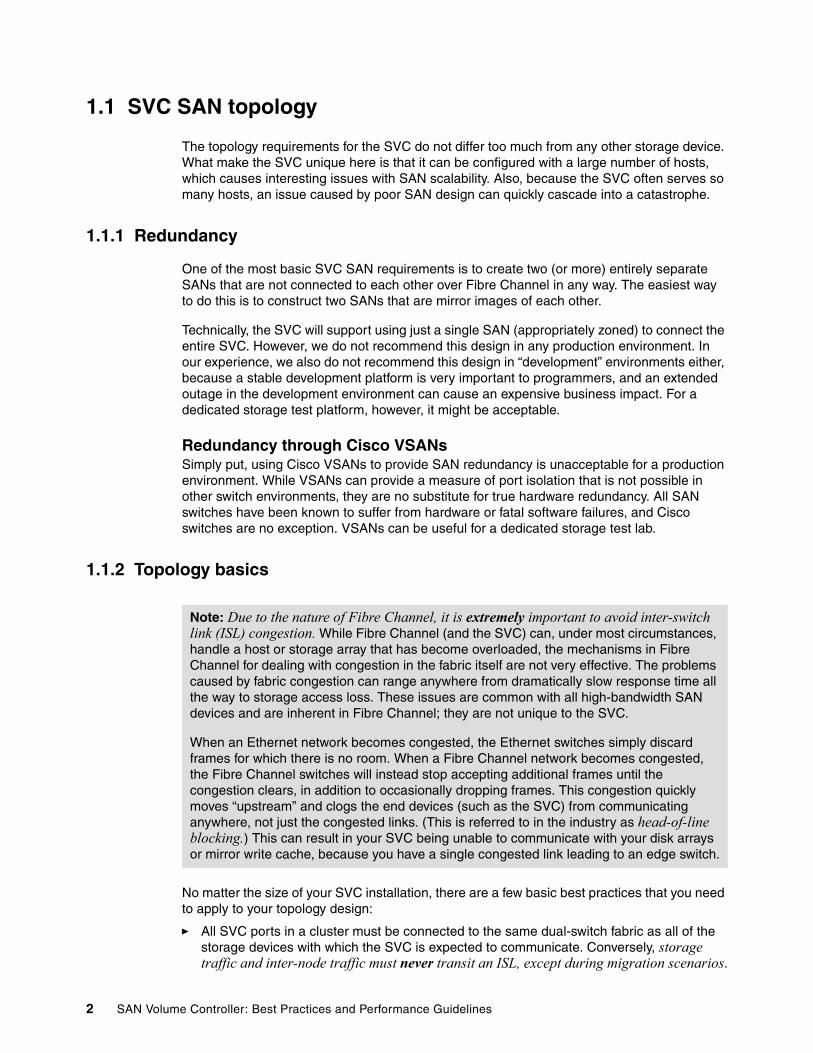
1.1 SVC SAN topology
The topology requirements for the SVC do not differ too much from any other storage device. What make the SVC unique here is that it can be configured with a large number of hosts, which causes interesting issues with SAN scalability. Also, because the SVC often serves so many hosts, an issue caused by poor SAN design can quickly cascade into a catastrophe.
1.1.1 Redundancy
One of the most basic SVC SAN requirements is to create two (or more) entirely separate SANs that are not connected to each other over Fibre Channel in any way. The easiest way to do this is to construct two SANs that are mirror images of each other.
Technically, the SVC will support using just a single SAN (appropriately zoned) to connect the entire SVC. However, we do not recommend this design in any production environment. In our experience, we also do not recommend this design in “development” environments either, because a stable development platform is very important to programmers, and an extended outage in the development environment can cause an expensive business impact. For a dedicated storage test platform, however, it might be acceptable.
Redundancy through Cisco VSANsSimply put, using Cisco VSANs to provide SAN redundancy is unacceptable for a production environment. While VSANs can provide a measure of port isolation that is not possible in other switch environments, they are no substitute for true hardware redundancy. All SAN switches have been known to suffer from hardware or fatal software failures, and Cisco switches are no exception. VSANs can be useful for a dedicated storage test lab.
1.1.2 Topology basics
No matter the size of your SVC installation, there are a few basic best practices that you need to apply to your topology design:
� All SVC ports in a cluster must be connected to the same dual-switch fabric as all of the storage devices with which the SVC is expected to communicate. Conversely, storage traffic and inter-node traffic must never transit an ISL, except during migration scenarios.
Note: Due to the nature of Fibre Channel, it is extremely important to avoid inter-switch link (ISL) congestion. While Fibre Channel (and the SVC) can, under most circumstances, handle a host or storage array that has become overloaded, the mechanisms in Fibre Channel for dealing with congestion in the fabric itself are not very effective. The problems caused by fabric congestion can range anywhere from dramatically slow response time all the way to storage access loss. These issues are common with all high-bandwidth SAN devices and are inherent in Fibre Channel; they are not unique to the SVC.
When an Ethernet network becomes congested, the Ethernet switches simply discard frames for which there is no room. When a Fibre Channel network becomes congested, the Fibre Channel switches will instead stop accepting additional frames until the congestion clears, in addition to occasionally dropping frames. This congestion quickly moves “upstream” and clogs the end devices (such as the SVC) from communicating anywhere, not just the congested links. (This is referred to in the industry as head-of-line blocking.) This can result in your SVC being unable to communicate with your disk arrays or mirror write cache, because you have a single congested link leading to an edge switch.
2 SAN Volume Controller: Best Practices and Performance Guidelines
� High-bandwidth-utilization servers (such as tape backup servers) must also be on the same switch as the SVC. Putting them on a separate switch can cause unexpected SAN congestion problems. Putting a high-bandwidth server on an edge switch is a waste of an ISL.
� If at all possible, plan for the maximum size configuration that you ever expect your SVC cluster to reach. As you will see in later parts of this chapter, the design of the SAN can change radically for larger numbers of hosts. Modifying the SAN later to accommodate a larger-than-expected number of hosts will either produce a poorly-designed SAN or be very difficult, expensive, and disruptive to your business. This does not mean that you need to purchase all of the SAN hardware initially, just that you need to lay out the SAN while keeping the maximum size in mind.
� Always deploy at least one “extra” ISL per switch. Not doing so opens you up to consequences from complete path loss (this is bad) to fabric congestion (this is even worse).
� The SVC does not permit the number of hops between the SVC and the hosts to exceed three hops. This typically is not a problem.
1.1.3 ISL oversubscription
The IBM System Storage SAN Volume Controller Configuration Guide, SC23-6628, specifies a suggested maximum host port to ISL ratio of 7:1. With modern 4 GBps switches, this implies an average bandwidth (in one direction) per host port of approximately 57 MBps. It you do not expect most of your hosts to reach anywhere near that value, it is possible to request an exception to this rule (known as a Request for Price Quotation (RPQ) in IBM) from your IBM marketing representative. Before doing so, however, keep the following factors in mind:
� You must take peak loads into consideration, not average loads. For instance, while a database server might only use 20 MBps during regular production workloads, it might perform a backup at far higher data rates.
� Congestion to one switch in a large fabric can cause performance issues throughout the entire fabric, including traffic between SVC nodes and storage, even if they are not directly attached to the congested switch. (The reasons for this are inherent to Fibre Channel flow control mechanisms, which are simply not designed to handle fabric congestion). This means that any estimates for required bandwidth prior to implementation must have a safety factor built into the estimate.
� On top of the safety factor for traffic expansion, implement a spare ISL or ISL trunk, as stated in the previous section. You need to still be able to avoid congestion if an ISL were to go down due to issues such as switch line card failure.
� Exceeding the “standard” 7:1 oversubscription ration will require you to implement fabric bandwidth threshold alerts. Anytime that one of your ISLs exceeds 70%, you need to schedule fabric changes to spread out the load further.
� You need to also consider the bandwidth consequences of a complete fabric outage. While this is a fairly rare event, insufficient bandwidth can turn a single-SAN outage into a total access loss event.
� Take the bandwidth of the links into account. It is very common to have ISLs run faster than host ports, which obviously reduces the number of required ISLs.
The RPQ process will involve a review of your proposed SAN design to ensure that it is reasonable for your proposed environment.
Chapter 1. SAN fabric 3

1.1.4 IBM 2109-M12/Brocade 12000 in an SVC environment
This model of SAN switch is well suited for the edge switch in a core-edge fabric.
A fully configured 64-port domain is made up of 16 4-port “quads”, organized into columns (line cards) and horizontal rows (see Figure 1-1). Each quad is connected via internal 2 Gb links to the other quads in its column and row. The routing between any specific pair of quads always traverses the same links, and this routing is not adjusted for traffic levels or congestion.
All if this means that your ISLs (each of which can be up to a four-port trunk) need to be on separate line cards and separate horizontal rows. The host ports on the switch must be evenly distributed among the remaining quads.
Most importantly, SVC ports must be distributed so that each quad has no more than one SVC port.
Figure 1-1 2109-M12/Brocade 12000 domain internal architecture
1.1.5 Switch port layout for large edge switches
While users of smaller switches generally do not need to concern themselves with which ports go where, users of multi-slot directors must pay careful attention to where the ISLs are
4 SAN Volume Controller: Best Practices and Performance Guidelines
located in the switch. Generally, the ISLs (or ISL trunks) need to be on separate line cards within the switch. The hosts must be spread out evenly among the remaining line cards in the switch. Remember to locate high-bandwidth hosts on the core switches directly.
1.1.6 Switch port layout and hardware selection for director-class core switches
Each switch vendor has a selection of line cards available. Some of these line cards are oversubscribed, and some of them have full bandwidth available for the attached devices. For your core switches, we suggest only using line cards where the full line speed that you expect to use will be available. You need to contact your switch vendor for full line card details. (They change too rapidly for practical inclusion in this publication).
Your SVC ports, storage ports, ISLs, and high-bandwidth hosts need to be spread out evenly among your line cards in order to help prevent the failure of any one line card from causing undue impact to performance or availability.
1.1.7 Single switch SVC SANs
The most basic SVC topology consists of nothing more than a single switch per SAN. This can be anything from a 16-port 1U switch for a small installation of just a few hosts and storage devices all the way up to a director taking up half a rack and filled with 48-port line cards. This design obviously has the advantage of simplicity, and it is a sufficient architecture for small to medium SVC installations.
It is preferable to use a large director-class single switch over setting up a core-edge fabric made up solely of lower-end switches.
As stated in 1.1.2, “Topology basics” on page 2, keep the maximum planned size of the installation in mind if you decide to use this architecture. If you run too low on ports, expansion can be very difficult.
1.1.8 Basic core-edge topology
The core-edge topology must be easily recognized by most SAN architects, as illustrated in Figure 1-2 on page 6. It consists of a switch in the center (usually, a director-class switch) and is surrounded by other switches. The core switch contains all SVC ports, storage ports, and high-bandwidth hosts. It is connected via ISLs to the edge switches.
The edge switches can be of any size. If they are multi-slot directors, they are usually fitted with at least some oversubscribed line cards, because the vast majority of hosts do not ever require line-speed bandwidth, or anything even close to it. Note that ISLs must not be on oversubscribed ports.
Chapter 1. SAN fabric 5

Figure 1-2 Core-edge topology
1.1.9 Four-SAN core-edge topology
For installations where even a core-edge fabric made up of switches completely filled with line cards is insufficient, you can instead install your SVC fabric split up into four SANs. This design is especially useful for large, multi-cluster installations. As with a regular core-edge, the edge switches can be of any size.
As you can see in Figure 1-3 on page 7, we have attached the SVC to each of four independent fabrics. For obvious reasons, you must storage devices with at least four ports with this design, although it is not required.
Core Switch Core Switch
SVC Node SVC Node
Edge Switch Edge SwitchEdge SwitchEdge Switch
Host Host
2
2
2 2 2 2
2
6 SAN Volume Controller: Best Practices and Performance Guidelines

Figure 1-3 Four-SAN core-edge topology
While some clients have chosen to simplify management by connecting the SANs together into pairs with a single ISL, we do not recommend this design. With only a single ISL connecting fabrics together, a small zoning mistake can quickly lead to severe SAN congestion.
1.1.10 Cisco VSANs
It is possible to use Cisco VSANs, combined with inter-VSAN routes, to isolate the hosts from the storage arrays. This provides little benefit for a great deal of added configuration complexity.
That being said, VSANs with inter-VSAN routes can be useful for fabric migrations from non-Cisco vendors onto Cisco fabrics, or other short-term situations. VSANs can also be useful if you have hosts that access the storage directly, along with virtualizing some of it with the SVC. (In this instance, it is best to use separate storage ports for the SVC and the hosts. We do not advise using inter-VSAN routes to enable port sharing).
Core Switch Core Switch
SVC Node SVC Node
Edge Switch Edge SwitchEdge SwitchEdge Switch
Host Host
2 2 2 2
Core Switch Core Switch
Chapter 1. SAN fabric 7

1.1.11 Common topology issues
In this section, we describe common topology problems encountered.
Accidentally accessing storage over ISLsOne common topology mistake that we have encountered in the field is to have SVC paths from the same node to the same disk array on multiple core switches that are linked together (see Figure 1-4). This is commonly encountered in environments where the SVC is not the only device accessing the disk array.
Figure 1-4 Spread out disk paths
If you have this type of a topology, it is very important to zone the SVC so that it will only see the paths on the same switch as the SVC nodes.
Because of the way that the SVC load balances traffic between the nodes and MDisks, the amount of traffic that transits your ISLs will be unpredictable and vary significantly. If you have
Note: This means you must have more restrictive zoning than what is detailed in 1.5.6, “Sample standard SVC zoning configuration” on page 16.
Switch
SVC Node SVC Node
SVC-attach host Non-SVC-attach host
Switch Switch Switch
2 2
SVC -> Storage Traffic should be zoned to never
travel over these links
2 2
8 SAN Volume Controller: Best Practices and Performance Guidelines

a Cisco fabric, this might be a place where Cisco VSANs are useful to help enforce the separation.
Accessing disk over an ISL on purposeThis practice is explicitly advised against in the SVC configuration guidelines, because the consequences of SAN congestion to your disk connections can be quite severe. Only use this configuration in SAN migration scenarios, and even then, great thought needs to be given to avoiding it if at all possible.
I/O Group splittingIt is common that clients want to attach another I/O Group for increased host capacity, but they lack the switch ports to do so. If this happens to you, there are two options:
� Completely overhaul the SAN during a complicated and painful re-architecture.
� Add a new core switch, and inter-switch link the new I/O Group and the new switch back to the original, as illustrated in Figure 1-5.
Figure 1-5 Proper I/O Group splitting
Old Switch
SVC Node SVC Node
Host Host
New Switch Old Switch New Switch
SVC -> Storage Traffic should be zoned and
masked to never travel over these links, but they should be zoned for intra-Cluster communications
SVC Node SVC Node
Old I/O Group New I/O Group
2 2 2 2 2 2 22
Chapter 1. SAN fabric 9
This is a valid configuration, but you must take certain precautions:
� As stated in “Accidentally accessing storage over ISLs” on page 8, zone and mask the SAN/disks so that you do not access the disk arrays over the ISLs. This means your disk arrays will need connections to both switches.
� You must have two dedicated ISLs between the two switches on each SAN with no data traffic traveling over them. The reason for this design is because if this link ever becomes congested or lost, you might experience problems with your SVC cluster if there are also issues at the same time on the other SAN. If you can, set a 5% traffic threshold alert on the ISLs so that you know if a zoning mistake has allowed any data traffic over the links.
1.2 Tape and disk on your SAN
If you have free ports on your core switch, there is no problem with putting tape devices (and their associated backup servers) on the SVC SAN; however, you must not put tape and disk traffic on the same Fibre Channel host bus adapter (HBA). Cisco VSANs can be useful here.
Do not put tape ports and backup servers on different switches. Modern tape devices have high bandwidth requirements and to do so can quickly lead to SAN congestion over the ISL between the switches if you configure it that way.
1.3 Switch interoperability
The SVC is rather flexible as far as switch vendors are concerned. The most important requirement is that all of the node connections on a particular SAN must all go to switches of a single vendor. This means that you must not have some nodes or node ports plugged into vendor A, and some nodes or node ports plugged into vendor B. If you follow the best practices mentioned in 1.1, “SVC SAN topology” on page 2, this is not an issue, because all of those connections must be on the exact same switch anyway.
While the SVC supports some combinations of SANs made up of switches from multiple vendors in the same SAN; in practice, we do not particularly recommend this approach. Despite years of effort, interoperability among switch vendors is less than ideal, because the Fibre Channel standards are not rigorously enforced. Interoperability problems between switch vendors are notoriously difficult and disruptive to isolate, and it can take a long time to obtain a fix. For these reasons, we suggest only running multiple switch vendors in the same SAN long enough to migrate from one vendor to another, if this is possible with your hardware.
It is acceptable to run a mixed-vendor SAN is if you have gained agreement from both switch vendors that they will fully support attachment with each other. At the time that we wrote this book, the QLogic/BladeCenter® FCSM will work with Cisco and McDATA. (“McData” here refers to the switch products sold by McDATA prior to their acquisition by Brocade. Much of that product line is still for sale at this time). Brocade will interoperate with McDATA under limited circumstances (contact Brocade for details). We do not advise interoperating Cisco with Brocade at this time, except during fabric migrations, and only then if you have a backout
Note: It is not a best practice to use this configuration to perform mirroring between I/O Groups within the same cluster. And, you must never split the two nodes in an I/O Group between different switches. However, in a dual-fabric configuration, half of the node’s ports must remain on the same switch with the other half of the ports on another switch.
10 SAN Volume Controller: Best Practices and Performance Guidelines
plan in place. We also do not advise that you connect the QLogic/BladeCenter FCSM to Brocade at this time.
In any fabric in which a BladeCenter FCSM is installed, do not perform any zoning operations from the FCSM. Perform them all from your core fabric.
1.4 Distance extension for mirroring
To implement remote mirroring over a distance, you have several choices:
� Optical multiplexors, such as DWDM or CWDM devices� Long-distance SFPs/XFPs� Fibre Channel → IP conversion boxes
Of those options, the optical flavors of distance extension are the “gold standard”. IP distance extension introduces additional complexity, is less reliable, and has substantial performance limitations. However, we do recognize that optical distance extension is impractical in many cases due to cost or unavailability.
1.4.1 Optical multiplexors
Optical multiplexors can extend your SAN up to hundreds of kilometers at extremely high speeds, and for this reason, they are the preferred method of distance expansion. When deploying optical multiplexing, make sure that it has been certified to work with your switch vendor. The SVC itself has no allegiance to a particular model of optical multiplexor.
If you use multiplexor-based distance extension, closely monitor your physical link error counts in your switches. These are high-precision devices. When they shift out of calibration, you will start to see errors in your frames, even if the dense wavelength division multiplexing (DWDM) thinks everything is just fine.
1.4.2 Long-distance SFPs/XFPs
Long-distance optical transceivers have the advantage of extreme simplicity. No expensive equipment is required and there are no configuration steps to perform. However, ensure you only use transceivers designed for your particular switch. Each switch vendor will only support a specific set of small form-factor pluggable transceivers (SFPs), so it is unlikely that Cisco SFPs will work in a Brocade switch.
1.4.3 Fibre Channel: IP Conversion
This is by far the most common and least expensive form of distance extension. It is also a form of distance extension that is complicated to configure, and relatively subtle errors can have severe performance implications.
Note: Distance extension must only be utilized for links between clusters. It must not be used for intra-cluster links. Technically, distance extension is supported for relatively short distances (a few kilometers). Refer to the IBM System Storage SAN Volume Controller Configuration Requirements and Limitations document, S1003093, for details explaining why this is not recommended.
Chapter 1. SAN fabric 11
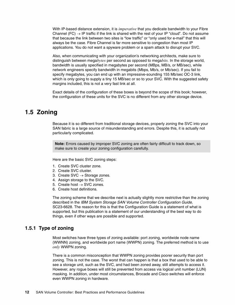
With IP-based distance extension, it is imperative that you dedicate bandwidth to your Fibre Channel (FC) → IP traffic if the link is shared with the rest of your IP “cloud”. Do not assume that because the link between two sites is “low traffic” or “only used for e-mail” that this will always be the case. Fibre Channel is far more sensitive to congestion than most IP applications. You do not want a spyware problem or a spam attack to disrupt your SVC.
Also, when communicating with your organization’s networking architects, make sure to distinguish between megabytes per second as opposed to megabits. In the storage world, bandwidth is usually specified in megabytes per second (MBps, MB/s, or MB/sec), while network engineers specify bandwidth in megabits (Mbps, Mb/s, or Mb/sec). If you fail to specify megabytes, you can end up with an impressive-sounding 155 Mb/sec OC-3 link, which is only going to supply a tiny 15 MB/sec or so to your SVC. With the suggested safety margins included, this is not a very fast link at all.
Exact details of the configuration of these boxes is beyond the scope of this book; however, the configuration of these units for the SVC is no different from any other storage device.
1.5 Zoning
Because it is so different from traditional storage devices, properly zoning the SVC into your SAN fabric is a large source of misunderstanding and errors. Despite this, it is actually not particularly complicated.
Here are the basic SVC zoning steps:
1. Create SVC cluster zone.2. Create SVC cluster.3. Create SVC → Storage zones.4. Assign storage to the SVC.5. Create host → SVC zones.6. Create host definitions.
The zoning scheme that we describe next is actually slightly more restrictive than the zoning described in the IBM System Storage SAN Volume Controller Configuration Guide, SC23-6628. The reason for this is that the Configuration Guide is a statement of what is supported, but this publication is a statement of our understanding of the best way to do things, even if other ways are possible and supported.
1.5.1 Type of zoning
Most switches have three types of zoning available: port zoning, worldwide node name (WWNN) zoning, and worldwide port name (WWPN) zoning. The preferred method is to use only WWPN zoning.
There is a common misconception that WWPN zoning provides poorer security than port zoning. This is not the case. The worst that can happen is that a box that used to be able to see a storage unit, such as the SVC, and had been zoned away, still attempts to access it. However, any rogue boxes will still be prevented from access via logical unit number (LUN) masking. In addition, under most circumstances, Brocade and Cisco switches will enforce even WWPN zoning in hardware.
Note: Errors caused by improper SVC zoning are often fairly difficult to track down, so make sure to create your zoning configuration carefully.
12 SAN Volume Controller: Best Practices and Performance Guidelines
There are multiple reasons not to use WWNN zoning. For hosts, it is absolutely a bad idea, because the WWNN is often based on the WWPN of only one of the HBAs. If you have to replace that HBA, the WWNN of the box will change on both fabrics, which will result in access loss. In addition, it also makes troubleshooting more difficult, because you have no consolidated list of which ports are supposed to be in which zone, and therefore, it is difficult to tell if a port is missing.
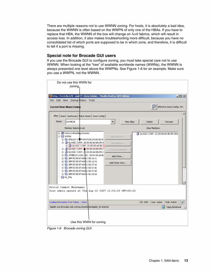
Special note for Brocade GUI usersIf you use the Brocade GUI to configure zoning, you must take special care not to use WWNN. When looking at the “tree” of available worldwide names (WWNs), the WWNN is always presented one level above the WWPNs. See Figure 1-6 for an example. Make sure you use a WWPN, not the WWNN.
Figure 1-6 Brocade zoning GUI
Use this WWN for zoning
Do not use this WWN for zoning
Chapter 1. SAN fabric 13

1.5.2 Pre-zoning tips and shortcuts
Now, we describe several tips and shortcuts.
AliasesThe biggest time-saver when creating your SVC zones is to use zoning aliases, if they are available on your particular switch. They will make your zoning much easier to configure and understand, and the likelihood of errors will be much less.
The aliases we are suggesting you create here take advantage of the fact that aliases can contain multiple members, just like zones.
Create aliases for each of the following:
� One that holds all the SVC ports on each fabric
� One for each storage controller (or controller blade, in the case of DS4x000 units)
� One for each I/O Group port pair (that is, it needs to contain node 0, port 2, and node 1, port 2)
It is usually not necessary to create aliases for your host ports.
Naming conventionRefer to 13.6, “Naming convention” on page 251 for suggestions for an SVC naming convention. A poor naming convention can make your zoning configuration very difficult to understand and maintain.
1.5.3 SVC cluster zone
This zone needs to contain every SVC port on the SAN. While it will overlap with every single one of the storage zones that you will create soon, it is very handy to have this zone in there as a “fail-safe” in case you ever make a mistake with your storage zones.
1.5.4 SVC: Storage zones
You need to avoid zoning different vendor storage controllers together; the ports from the storage controller need to be split evenly across the dual fabrics. Each controller might have its own recommended best practice.
DS4x00 and FAStT storage controllersEach DS4x00 and FAStT array controller consists of two separate blades. It is a best practice that these two blades are not in the same zone if you have attached them to the same SAN. There might be a similar best practice suggestion from non-IBM storage vendors; contact them for details.
1.5.5 SVC: Host zones
There must be a single zone for each host port. This zone must contain the host port, and one port from each SVC node that the host will need to access. While there will be two ports from each node on the SAN, make sure that the host only accesses one of them. Refer to Figure 1-7 on page 15 for reference.
14 SAN Volume Controller: Best Practices and Performance Guidelines

This configuration will give you four paths to each VDisk, which is the number of paths per VDisk for which IBM Subsystem Device Driver (SDD) and the SVC have been tuned.
Figure 1-7 Typical host → SVC zoning
The IBM System Storage SAN Volume Controller Software Installation and Configuration Guide, SC23-662, discusses putting many hosts into a single zone as a supported configuration under some circumstances. While this will usually work just fine, instability in one of your hosts can trigger all sorts of impossible to diagnose problems in the other hosts in the zone. For this reason, you need to only have a single host in each zone.
It is a supported configuration to have eight paths to each VDisk, but this provides no performance benefit (indeed, under some circumstances, it can even reduce performance), and it does not improve reliability or availability by any significant degree.
Hosts with four (or more) HBAsIf you have four HBAs in your host instead of two HBAs, it takes a little more planning. Because eight paths are not an optimum number, you must instead configure your SVC Host Definitions (and zoning) as though the single host is two separate hosts. During VDisk assignment, you alternate which VDisk was assigned to one of the “pseudo-hosts”.
The reason we do not just assign one HBA to each of the paths is because, for any specific VDisk, one node solely serves as a backup node. The load is never going to get balanced for that particular VDisk. It is better to load balance by I/O Group instead, and let the VDisks get automatically assigned to nodes.
Switch B
ZoneFoo_Slot5_SAN_B
ZoneBar_Slot8_SAN_B
Switch A
ZoneFoo_Slot3_SAN_A
ZoneBar_Slot2_SAN_A
I/O Group 0
Zone: Foo_Slot3_SAN_A 50:00:11:22:33:44:55:66 SVC_Group0_Port_AZone: Bar_Slot2_SAN_A 50:11:22:33:44:55:66:77 SVC_Group0_Port_C
Zone: Foo_Slot5_SAN_B 50:00:11:22:33:44:55:67 SVC_Group0_Port_DZone: Bar_Slot8_SAN_B 50:11:22:33:44:55:66:78 SVC_Group0_Port_B
Host Foo Host Bar
SVC Node
A B C DSVC Node
A B C D
Chapter 1. SAN fabric 15
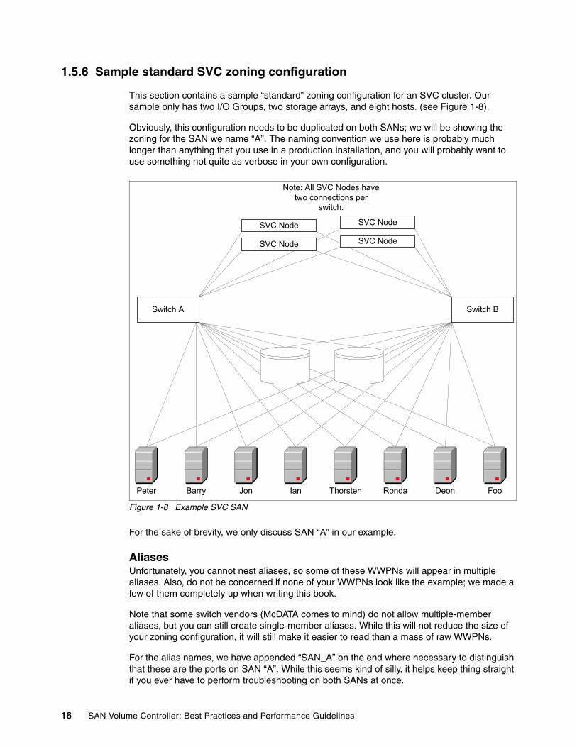
1.5.6 Sample standard SVC zoning configuration
This section contains a sample “standard” zoning configuration for an SVC cluster. Our sample only has two I/O Groups, two storage arrays, and eight hosts. (see Figure 1-8).
Obviously, this configuration needs to be duplicated on both SANs; we will be showing the zoning for the SAN we name “A”. The naming convention we use here is probably much longer than anything that you use in a production installation, and you will probably want to use something not quite as verbose in your own configuration.
Figure 1-8 Example SVC SAN
For the sake of brevity, we only discuss SAN “A” in our example.
AliasesUnfortunately, you cannot nest aliases, so some of these WWPNs will appear in multiple aliases. Also, do not be concerned if none of your WWPNs look like the example; we made a few of them completely up when writing this book.
Note that some switch vendors (McDATA comes to mind) do not allow multiple-member aliases, but you can still create single-member aliases. While this will not reduce the size of your zoning configuration, it will still make it easier to read than a mass of raw WWPNs.
For the alias names, we have appended “SAN_A” on the end where necessary to distinguish that these are the ports on SAN “A”. While this seems kind of silly, it helps keep thing straight if you ever have to perform troubleshooting on both SANs at once.
Switch A Switch B
Jon Ian
SVC Node SVC Node
SVC Node SVC Node
Note: All SVC Nodes have two connections per
switch.
FooBarryPeter Thorsten Ronda Deon
16 SAN Volume Controller: Best Practices and Performance Guidelines
SVC cluster aliasAs a side note, the SVC has a very predictable WWPN structure. This can help make the zoning easier to “read”. It always starts with 50:05:07:68 (see Example 1-1) and ends with two octets that will distinguish for you which node is which. The first digit of the third octet from the end is the port number on the node.
The cluster alias that we create will be used for the cluster-only zone, for all storage zones, and also in any zones that you need for remote mirroring (which will not be discussed in this example).
Example 1-1 SVC cluster alias
SVC_Cluster_SAN_A:50:05:07:68:01:10:37:e550:05:07:68:01:30:37:e550:05:07:68:01:10:37:dc50:05:07:68:01:30:37:dc50:05:07:68:01:10:1d:1c50:05:07:68:01:30:1d:1c50:05:07:68:01:10:27:e250:05:07:68:01:30:27:e2
SVC I/O Group “port pair” aliasesThese are the basic “building-blocks” of our host zones. Because the best practices we have described specify that each HBA is only supposed to see a single port on each node, these are the aliases that will be included. You need to obviously roughly alternate between the ports when creating your host zones. See Example 1-2.
Example 1-2 I/O Group port pair aliases
SVC_Group0_Port1:50:05:07:68:01:10:37:e550:05:07:68:01:10:37:dc
SVC_Group0_Port3:50:05:07:68:01:30:37:e550:05:07:68:01:30:37:dc
SVC_Group1_Port1:50:05:07:68:01:10:1d:1c50:05:07:68:01:10:27:e2
SVC_Group1_Port3:50:05:07:68:01:30:1d:1c50:05:07:68:01:30:27:e2
Storage controller aliasesThe first two aliases here are similar to what you might see with a DS4800 storage array with four back-end ports per controller blade. We have created different aliases for each blade in order to isolate the two controllers from each other. This is a best practice suggested by DS4x00 development.
Because the DS8000 has no concept of separate controllers (at least, not from the viewpoint of a SAN), we are just putting all the ports on the device into a single alias. See Example 1-3 on page 18.
Chapter 1. SAN fabric 17

Example 1-3 Storage aliases
DS4k_23K45_Blade_A_SAN_A20:04:00:a0:b8:17:44:3220:04:00:a0:b8:17:44:33
DS4k_23K45_Blade_B_SAN_A20:05:00:a0:b8:17:44:3220:05:00:a0:b8:17:44:33
DS8k_34912_SAN_A50:05:00:63:02:ac:01:4750:05:00:63:02:bd:01:3750:05:00:63:02:7f:01:8d50:05:00:63:02:2a:01:fc
ZonesOne thing to keep in mind when naming your zones is that they cannot have identical names as aliases.
Here is our sample zone set, utilizing the aliases that we have just defined.
Cluster zoneThis one is pretty simple; it only contains a single alias (which happens to contain all of the SVC ports). And yes, this zone does overlap with every single one of the storage zones. Nevertheless, it is nice to have it there as a fail-safe, given the dire consequences that will occur if your cluster nodes ever completely lose contact with one another over the SAN. See Example 1-4.
Example 1-4 SVC cluster zone
SVC_Cluster_Zone_SAN_A:SVC_Cluster_SAN_A
SVC → Storage zonesAs we have mentioned earlier, we are going to put each of the storage controllers (and, in the case of the DS4x00 controllers, each blade) into a separate zone. See Example 1-5.
Example 1-5 SVC → Storage zones
SVC_DS4k_23K45_Zone_Blade_A_SAN_A:SVC_Cluster_SAN_ADS4k_23K45_Blade_A_SAN_A
SVC_DS4k_23K45_Zone_Blade_B_SAN_A:SVC_Cluster_SAN_ADS4K_23K45_BLADE_B_SAN_A
SVC_DS8k_34912_Zone_SAN_A:SVC_Cluster_SAN_ADS8k_34912_SAN_A
18 SAN Volume Controller: Best Practices and Performance Guidelines

SVC → Host zonesWe have not created aliases for each host, because each host is only going to appear in a single zone. While there will be a “raw” WWPN in the zones, an alias is unnecessary, because it will be obvious where the WWPN belongs.
Notice that all of the zones refer to the slot number of the host, rather than “SAN_A”. This is because if you are trying to diagnose a problem (or replace an HBA), it is very important to know on which HBA you need to work.
For System p® hosts, we have also appended the FCS number into the zone name. This makes device management go a bit more smoothly. While it is possible to get this information out of SDD, it is nice to have it in the zoning configuration.
It is up to you if you want to include all of this in your own zoning configuration. We will discuss all this further in 1.5.7, “Zoning with multiple SVC clusters” on page 20.
We alternate the hosts between the Port1s and the Port3s and between the I/O Groups for load balancing. While we are just simply alternating in our example, you might want to balance the load based on the observed load on ports and I/O Groups. See Example 1-6.
Example 1-6 SVC → Host zones
WinPeter_Slot3:21:00:00:e0:8b:05:41:bcSVC_Group0_Port1
WinBarry_Slot7:21:00:00:e0:8b:05:37:abSVC_Group0_Port3
WinJon_Slot1:21:00:00:e0:8b:05:28:f9SVC_Group1_Port1
WinIan_Slot2:21:00:00:e0:8b:05:1a:6fSVC_Group1_Port3
AIXRonda_Slot6_fcs1:10:00:00:00:c9:32:a8:00SVC_Group0_Port1
AIXThorsten_Slot2_fcs0:10:00:00:00:c9:32:bf:c7SVC_Group0_Port3
AIXDeon_Slot9_fcs3:10:00:00:00:c9:32:c9:6fSVC_Group1_Port1
AIXFoo_Slot1_fcs2:10:00:00:00:c9:32:a8:67SVC_Group1_Port3
Chapter 1. SAN fabric 19

1.5.7 Zoning with multiple SVC clusters
Unless two clusters participate in a mirroring relationship, all zoning must be configured so that the two clusters do not share a zone. If a single host requires access to two different clusters, create two zones with each zone to a separate cluster. The storage zones must also be separate, even if the two clusters share a disk controller.
1.5.8 Split controller configurations
There might be situations where a storage controller is used both for SVC attachment and direct-attach hosts. In this case, it is important that you pay close attention during the LUN masking process on the storage array. Assigning the same LUN to both a host and the SVC will almost certainly result in swift data corruption. If you perform a migration into or out of the SVC, make sure that the LUN is removed from one place at the exact same time that it is added to another place.
1.6 Switch Domain IDs
All switch Domain IDs must be unique among both fabrics, and the name of the switch needs to incorporate the Domain ID. Having a domain ID that is totally unique makes troubleshooting problems much easier in situations where an error message contains the FCID of the port with a problem.
1.7 TotalStorage Productivity Center for Fabric
TotalStorage® Productivity Center (TPC) for Fabric can be used to create, administer, and monitor your Fabric. There is nothing “special” that you need to do to use it to administer an SVC fabric as opposed to any other disk fabric. We discuss information about on TPC for Fabric in Chapter 12, “Monitoring” on page 215.
For further information, consult the TPC IBM Redbooks publication, IBM TotalStorage Productivity Center V3.1: The Next Generation, SG24-7194, or contact your IBM marketing representative or IBM Business Partner.
20 SAN Volume Controller: Best Practices and Performance Guidelines

Chapter 2. SAN Volume Controller cluster
In this chapter, we discuss the advantages of virtualization and when to best use virtualization in your environment. Furthermore, we describe the scalability options for the IBM System Storage SAN Volume Controller (SVC) and when to grow or split an SVC cluster.
2
© Copyright IBM Corp. 2008. All rights reserved. 21
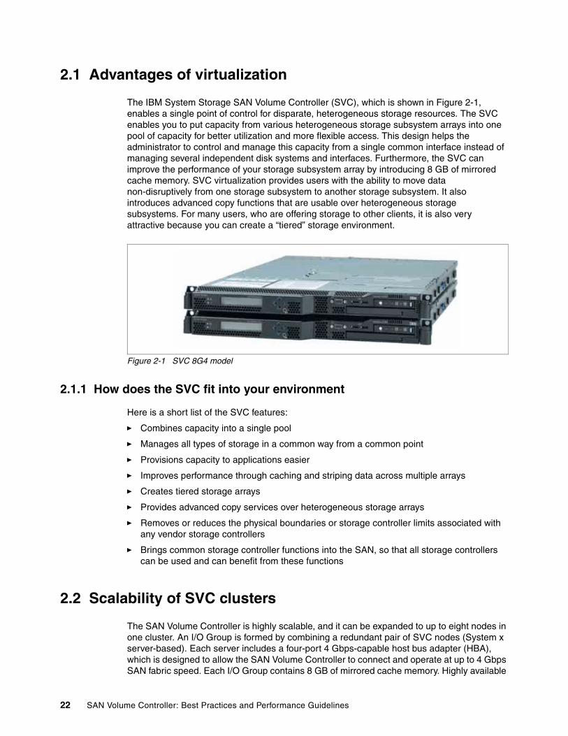
2.1 Advantages of virtualization
The IBM System Storage SAN Volume Controller (SVC), which is shown in Figure 2-1, enables a single point of control for disparate, heterogeneous storage resources. The SVC enables you to put capacity from various heterogeneous storage subsystem arrays into one pool of capacity for better utilization and more flexible access. This design helps the administrator to control and manage this capacity from a single common interface instead of managing several independent disk systems and interfaces. Furthermore, the SVC can improve the performance of your storage subsystem array by introducing 8 GB of mirrored cache memory. SVC virtualization provides users with the ability to move data non-disruptively from one storage subsystem to another storage subsystem. It also introduces advanced copy functions that are usable over heterogeneous storage subsystems. For many users, who are offering storage to other clients, it is also very attractive because you can create a “tiered” storage environment.
Figure 2-1 SVC 8G4 model
2.1.1 How does the SVC fit into your environment
Here is a short list of the SVC features:
� Combines capacity into a single pool
� Manages all types of storage in a common way from a common point
� Provisions capacity to applications easier
� Improves performance through caching and striping data across multiple arrays
� Creates tiered storage arrays
� Provides advanced copy services over heterogeneous storage arrays
� Removes or reduces the physical boundaries or storage controller limits associated with any vendor storage controllers
� Brings common storage controller functions into the SAN, so that all storage controllers can be used and can benefit from these functions
2.2 Scalability of SVC clusters
The SAN Volume Controller is highly scalable, and it can be expanded to up to eight nodes in one cluster. An I/O Group is formed by combining a redundant pair of SVC nodes (System x server-based). Each server includes a four-port 4 Gbps-capable host bus adapter (HBA), which is designed to allow the SAN Volume Controller to connect and operate at up to 4 Gbps SAN fabric speed. Each I/O Group contains 8 GB of mirrored cache memory. Highly available
22 SAN Volume Controller: Best Practices and Performance Guidelines

I/O Groups are the basic configuration element of a SAN Volume Controller cluster. Adding I/O Groups to the cluster is designed to linearly increase cluster performance and bandwidth. An entry-level SAN Volume Controller configuration contains a single I/O Group. The SAN Volume Controller can scale out to support four I/O Groups, and it can scale up to support 1,024 host servers. For every cluster, the SAN Volume Controller supports up to 4,096 virtual disks (VDisks). This configuration flexibility means that SAN Volume Controller configurations can start small with an attractive price to suit smaller clients or pilot projects and yet can grow to manage very large storage environments.
2.2.1 Advantage of multi cluster as opposed to single cluster
Growing or adding new I/O Groups to an SVC cluster is a decision which has to be made when either a configuration limit is reached or when the I/O load reaches a point where a new I/O Group is needed. For the current SVC hardware (8G4 nodes on an x3550) and SVC version 4.x, the saturation point for the configuration that we tested was reached at approximately 70,000 I/Os per second (IOPS) (see Table 2-2 on page 25).
After you reach the performance or configuration maximum limit, you can add additional performance or capacity by attaching an additional I/O Group to the SVC cluster.
Table 2-1shows the current maximum limits for one SVC I/O Group.
Table 2-1 Maximum configurations for an I/O Group
2.2.2 Performance expectations by adding an SVC
As shown in 2.2.1, “Advantage of multi cluster as opposed to single cluster” on page 23, there are limits that will cause the addition of a new I/O Group to the existing SVC cluster.
In Figure 2-2 on page 24, you can see the performance improvements by adding a new I/O Group to your SVC cluster. A single SVC cluster can reach a performance of more than 70,000 IOPS, given that the total response time will not pass five milliseconds. If this limit is close to being exceeded, you will need to add a second I/O Group to the cluster.
Objects Maximum number Comments
SAN Volume Controller nodes 8 Arranged as four I/O Groups
I/O Groups 4 Each containing two nodes
VDisks per I/O Group 1024 Includes managed-mode and image-mode VDisks
Host IDs per I/O Group 256 (Cisco, Brocade, McDATA)64 QLogic®
N/A
Host ports per I/O Group 512 (Cisco, Brocade, McDATA)128 QLogic
N/A
Metro Mirror and Global Mirror VDisks per I/O Group
40 TB The total size of all Metro Mirror source and target VDisks and all Global Mirror source and target VDisks in an I/O Group must not exceed 40 TB.
FlashCopy® VDisks per I/O Group
40 TB The total size of all FlashCopy targets or source VDisks in an I/O Group must not exceed 40 TB.
Chapter 2. SAN Volume Controller cluster 23
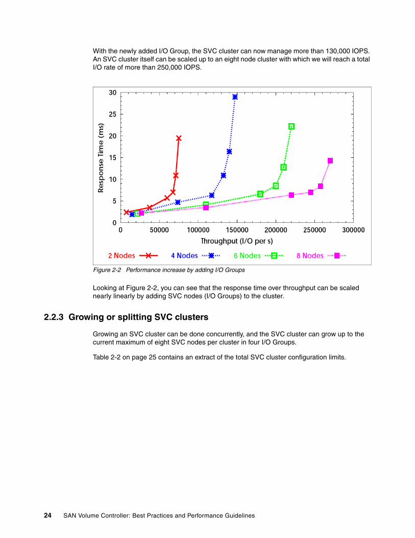
With the newly added I/O Group, the SVC cluster can now manage more than 130,000 IOPS. An SVC cluster itself can be scaled up to an eight node cluster with which we will reach a total I/O rate of more than 250,000 IOPS.
Figure 2-2 Performance increase by adding I/O Groups
Looking at Figure 2-2, you can see that the response time over throughput can be scaled nearly linearly by adding SVC nodes (I/O Groups) to the cluster.
2.2.3 Growing or splitting SVC clusters
Growing an SVC cluster can be done concurrently, and the SVC cluster can grow up to the current maximum of eight SVC nodes per cluster in four I/O Groups.
Table 2-2 on page 25 contains an extract of the total SVC cluster configuration limits.
24 SAN Volume Controller: Best Practices and Performance Guidelines
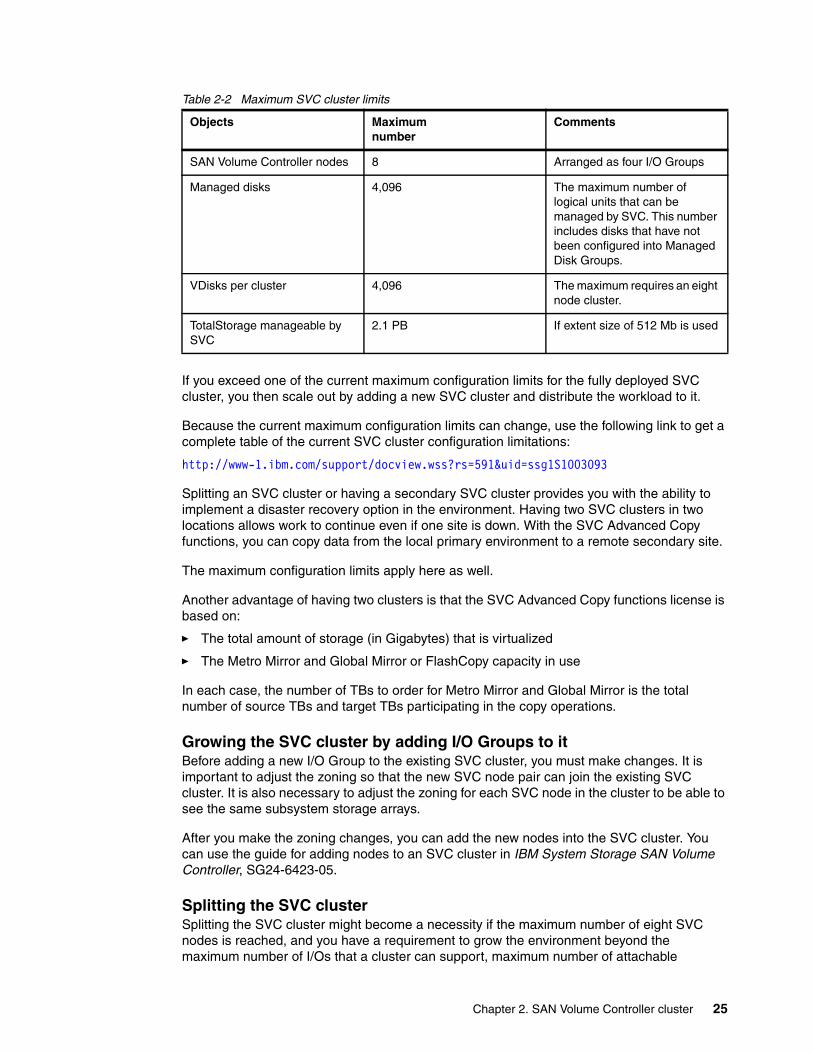
Table 2-2 Maximum SVC cluster limits
If you exceed one of the current maximum configuration limits for the fully deployed SVC cluster, you then scale out by adding a new SVC cluster and distribute the workload to it.
Because the current maximum configuration limits can change, use the following link to get a complete table of the current SVC cluster configuration limitations:
http://www-1.ibm.com/support/docview.wss?rs=591&uid=ssg1S1003093
Splitting an SVC cluster or having a secondary SVC cluster provides you with the ability to implement a disaster recovery option in the environment. Having two SVC clusters in two locations allows work to continue even if one site is down. With the SVC Advanced Copy functions, you can copy data from the local primary environment to a remote secondary site.
The maximum configuration limits apply here as well.
Another advantage of having two clusters is that the SVC Advanced Copy functions license is based on:
� The total amount of storage (in Gigabytes) that is virtualized
� The Metro Mirror and Global Mirror or FlashCopy capacity in use
In each case, the number of TBs to order for Metro Mirror and Global Mirror is the total number of source TBs and target TBs participating in the copy operations.
Growing the SVC cluster by adding I/O Groups to itBefore adding a new I/O Group to the existing SVC cluster, you must make changes. It is important to adjust the zoning so that the new SVC node pair can join the existing SVC cluster. It is also necessary to adjust the zoning for each SVC node in the cluster to be able to see the same subsystem storage arrays.
After you make the zoning changes, you can add the new nodes into the SVC cluster. You can use the guide for adding nodes to an SVC cluster in IBM System Storage SAN Volume Controller, SG24-6423-05.
Splitting the SVC cluster Splitting the SVC cluster might become a necessity if the maximum number of eight SVC nodes is reached, and you have a requirement to grow the environment beyond the maximum number of I/Os that a cluster can support, maximum number of attachable
Objects Maximumnumber
Comments
SAN Volume Controller nodes 8 Arranged as four I/O Groups
Managed disks 4,096 The maximum number of logical units that can be managed by SVC. This number includes disks that have not been configured into Managed Disk Groups.
VDisks per cluster 4,096 The maximum requires an eight node cluster.
TotalStorage manageable by SVC
2.1 PB If extent size of 512 Mb is used
Chapter 2. SAN Volume Controller cluster 25

subsystem storage controllers, or any other maximum mentioned in the V4.2.0 Configuration Requirements and Guidelines at:
http://www-1.ibm.com/support/docview.wss?rs=591&uid=ssg1S1003093
Instead of having one SVC cluster host all I/O operations, hosts, and subsystem storage attachments, the goal here is to create a second SVC cluster so that we equally distribute all of the workload over the two SVC clusters.
There are a number of approaches that you can take for splitting an SVC cluster:
� The first, and probably the easiest, way is to create a new SVC cluster, attach storage subsystems and hosts to it, and start putting workload on this new SVC cluster.
The next options are more intensive, and they involve performing more steps:
� Create new SVC clusters and start moving workload onto it. To move the workload from an existing SVC cluster to a new SVC cluster, you can use the Advanced Copy features, such as Metro Mirror and Global Mirror. We describe this scenario in Chapter 9, “Copy services” on page 143.
� You can use the VDisk “managed mode to image mode” migration to move workload from one SVC cluster to the new SVC cluster. Migrate a VDisk from manage mode to image mode, reassign the disk (logical unit number (LUN) masking) from your storage subsystem point of view, introduce the disk to your new SVC cluster, and use the image mode to manage mode migration. We describe this scenario in Chapter 8, “VDisks” on page 113.
From a user perspective, the first option is the easiest way to expand your cluster workload. The second and third options are more difficult, involve more steps, and require more preparation in advance. The third option is the choice that involves the longest outage to the host systems, and therefore, we do not prefer the third choice.
There is only one good reason that we can think of to reduce the existing SVC cluster by a certain amount of I/O Groups: If more bandwidth is required on the secondary SVC cluster, and there is spare bandwidth available on the primary cluster.
2.3 SVC cache improves subsystem performance
Disk storage subsystems with lower internal cache will have a performance value based on the amount of cache that they can offer. Introducing the SVC in front of these storage subsystems will improve the overall performance.
In the following example, we show a direct comparison from a direct-attached DS4000™ to a Windows® host. Later, we show the performance improvement by introducing the SVC in the datapath.
Note: This move involves an outage from the host system point of view, because the worldwide port name (WWPN) from the subsystem (SVC I/O Group) does change.
Note: This scenario also invokes an outage to your host systems and the I/O to the VDisk.
26 SAN Volume Controller: Best Practices and Performance Guidelines
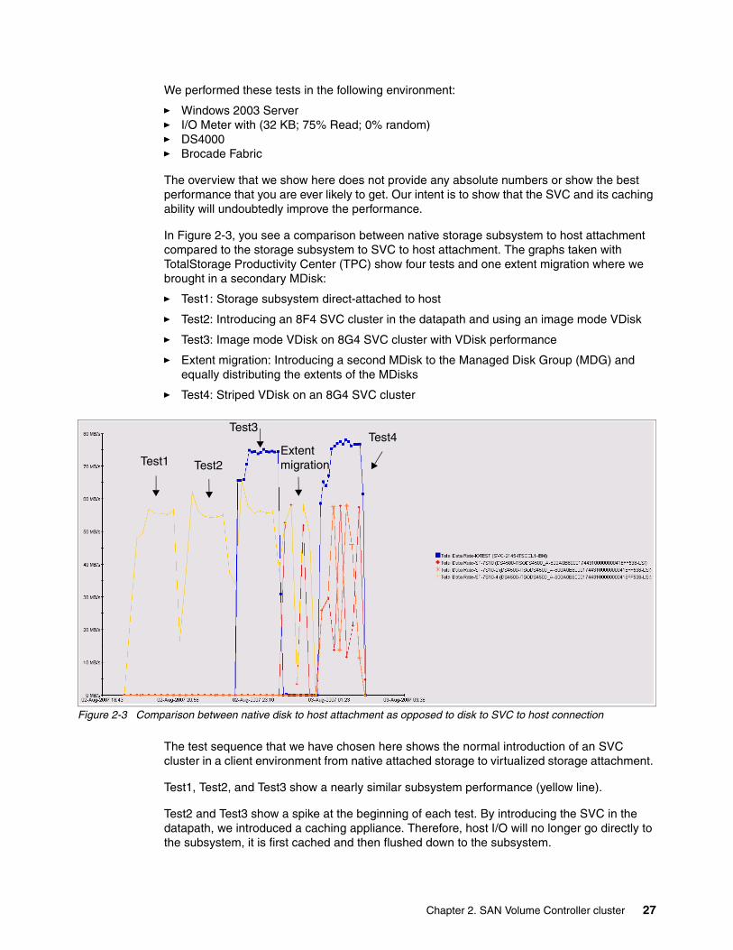
We performed these tests in the following environment:
� Windows 2003 Server � I/O Meter with (32 KB; 75% Read; 0% random)� DS4000� Brocade Fabric
The overview that we show here does not provide any absolute numbers or show the best performance that you are ever likely to get. Our intent is to show that the SVC and its caching ability will undoubtedly improve the performance.
In Figure 2-3, you see a comparison between native storage subsystem to host attachment compared to the storage subsystem to SVC to host attachment. The graphs taken with TotalStorage Productivity Center (TPC) show four tests and one extent migration where we brought in a secondary MDisk:
� Test1: Storage subsystem direct-attached to host
� Test2: Introducing an 8F4 SVC cluster in the datapath and using an image mode VDisk
� Test3: Image mode VDisk on 8G4 SVC cluster with VDisk performance
� Extent migration: Introducing a second MDisk to the Managed Disk Group (MDG) and equally distributing the extents of the MDisks
� Test4: Striped VDisk on an 8G4 SVC cluster
Figure 2-3 Comparison between native disk to host attachment as opposed to disk to SVC to host connection
The test sequence that we have chosen here shows the normal introduction of an SVC cluster in a client environment from native attached storage to virtualized storage attachment.
Test1, Test2, and Test3 show a nearly similar subsystem performance (yellow line).
Test2 and Test3 show a spike at the beginning of each test. By introducing the SVC in the datapath, we introduced a caching appliance. Therefore, host I/O will no longer go directly to the subsystem, it is first cached and then flushed down to the subsystem.
Test1 Test2
Test3Test4
Extent migration
Chapter 2. SAN Volume Controller cluster 27

Test3 shows, in addition to the subsystem performance, the performance for the VDisk (blue line). As we will explain later, we have a clear performance improvement from the host’s point of view.
The extent migration between Test3 and Test4 is the step where you move an image mode VDisk to a managed mode VDisk.
Test4 shows the performance of a striped VDisk (blue line) and two MDisks (red and orange lines).
In this section, we show you the value of the SVC cluster in your environment. For this purpose, we only compare Test1 and Test4.
In the chart in Figure 2-4, we compare the total, read, and write I/O per second (IOPS). The performance improvement that we saw here was approximately 27%.
Test1 is direct-attached, and Test4 is striped.
Figure 2-4 Native I/Ops native compared to SVC-attached storage
Figure 2-5 on page 29 shows the values for the total, read, and write MBps. Similar to the I/O rate, we saw a 27% improvement for the I/O traffic.
Test1 is direct-attached, and Test4 is striped.
I/Ops
0500
10001500200025003000
I/Ops Read I/Ops Write I/Ops
Test1Test4
28 SAN Volume Controller: Best Practices and Performance Guidelines

Figure 2-5 Native MBps compared to SVC-attached storage
For both parameters, I/Ops in Figure 2-4 on page 28 and MBps in Figure 2-5, we saw a large performance improvement by using the SVC.
2.3.1 Cache destage operations
This section discusses cache operations.
SVC internal cache handlingThe SVC cache is provided to improve performance of read and write commands by holding some read or write data in SVC memory. Because the nodes in an I/O Group have physically separate memories, the cache component must keep the caches on both nodes consistent. The caches will be consistent in that a read to either node will return the last data written through either node. The cache reduces the latency of read commands, because it can fetch blocks from memory instead of reading them from disk (that is, a read-hit). Additionally, when the cache detects a sequential read workload, it can prefetch blocks from disk to reduce latency on subsequent read commands. The cache reduces the latency of write commands by completing them without sending the written blocks to disk (that is, a fast-write).
The cache component secures fast-writes against a single failure by storing a copy of the written blocks on both nodes in a caching pair. In the event of a node failure or asymmetric VDisk path failure, the cache component will fail over to the surviving node and begin destaging all modified blocks in the cache. In the event of a power failure, both nodes in the caching pair will write all modified blocks in the cache to local disk. When the power is restored, the cache component will recover all the modified blocks from the local disk.
MB/s
0
10
20
30
40
50
60
70
80
90
Total MBps Read MBps Write MBps
Test1Test4
Chapter 2. SAN Volume Controller cluster 29
The cache component periodically reclaims resources used to cache blocks so that it can cache different blocks. The cache component uses a least recently used (LRU) policy for selecting those blocks that it will no longer cache.
However, the cache component will not be able to reclaim resources when the cache is full of pinned data. Pinned data is modified data for an offline VDisk, that is, it cannot be destaged, because the back-end disks are unavailable for I/O. For this reason, the cache component reserves a set of “short-term” resources that are not used to cache. The cache can use these resources to synchronously complete any read or write command. Therefore, the cache component can proceed with new read and write commands without waiting for the processing of existing read and write commands to complete.
Cache-disabled VDisksCache-disabled VDisks are useful:
� To allow the use of copy services in the underlying storage controllers
� To control the allocation of cache resources. By disabling the cache for some VDisks, more cache resources will be available to cache I/Os to other VDisks in the same I/O Group. This technique is particularly effective where an I/O Group is serving some VDisks, which will benefit from cache and other VDisks where the benefits of caching are small or nonexistent.
Currently, there is no direct way to enable the cache for a previously cache-disabled VDisk. There are three options to turn the VDisk caching mechanism on:
� If the VDisk is an image mode VDisk, you can remove the VDisk from the SVC cluster and redefine it with cache enabled.
� Use the SVC FlashCopy function to copy the content of the cache-disabled VDisk to a new cache-enabled VDisk. After the Flash Copy has been started, change the VDisk to host mapping to the new VDisk. This will involve an outage.
� Use the SVC Metro Mirror or Global Mirror function to mirror the data to another cache-enabled VDisk. As in the second option, you have to change the VDisk to host mapping after the mirror operation is done. This will involve an outage.
For more information about VDisk handling, see Chapter 8, “VDisks” on page 113.
2.4 Cluster upgrade
The SVC cluster is designed to perform a concurrent code update. Although it is a concurrent code update for the SVC, it is disruptive to upgrade certain other parts in a client environment, such as updating the multipathing driver. Before applying the SVC code update, the administrator needs to review the following Web page to ensure the compatibility between the SVC code and the SVC console GUI.
The SAN Volume Controller and SVC console GUI Compatibility Web site is:
http://www-1.ibm.com/support/docview.wss?rs=591&uid=ssg1S1002888
Furthermore, some concurrent upgrade paths are only available via an intermediate level. See the following Web page for more information:
SAN Volume Controller Concurrent Compatibility and Code Cross-Reference:
http://www-1.ibm.com/support/docview.wss?rs=591&uid=ssg1S1001707
30 SAN Volume Controller: Best Practices and Performance Guidelines

Even though the SVC code update is concurrent, we recommend that you perform several steps in advance:
� Before applying a code update, ensure that there are no open problems in your SVC, SAN, or storage subsystems. Use the “Run maintenance procedure” on the SVC and fix the open problems first. For more information, refer to 15.3.2, “Solving SVC problems” on page 272.
� It is also very important to check your host dual pathing. Make sure that from the host’s point of view that all paths are available. Missing paths can lead to I/O problems during the SVC code update. Refer to Chapter 10, “Hosts” on page 169 for more information about hosts.
� It is wise to schedule a time for the SVC code update during low I/O activity.
� Upgrade the master console GUI first.
� Allow the SVC code update to finish before making any other changes in your environment.
� Allow at least one hour to perform the code update for a single SVC I/O Group and 30 minutes for each additional I/O Group. In a worst case scenario, an update can take up to two hours, which implies that the SVC code update will also update the BIOS, SP, and the SVC service card.
New features are not available until all nodes in the cluster are at the same level.
Features, which are dependent on a remote cluster Metro Mirror or Global Mirror, might not be available until the remote cluster is at the same level. For more information, refer to 15.3.5, “Solving storage subsystem problems” on page 277.
Important: If the Concurrent Code Upgrade (CCU) appears to stop for a long time (up to an hour), this can occur, because it is upgrading a low level BIOS. Never power off during a CCU upgrade unless you have been instructed to do so by IBM service personnel. If the upgrade does encounter a problem and fails, it will back out the upgrade itself.
Chapter 2. SAN Volume Controller cluster 31

32 SAN Volume Controller: Best Practices and Performance Guidelines
Chapter 3. Master console
In this chapter, we describe how to manage important areas of the IBM System Storage SAN Volume Controller Master Console (MC), how to manage multiple MCs, how to save configurations from the IBM System Storage SAN Volume Controller (SVC) to the MC, and how to maintain passwords and IDs from the MC and the SVC. Furthermore, we provide information about IP considerations, audit logging, and how to use the audit logs.
3
© Copyright IBM Corp. 2008. All rights reserved. 33
3.1 Managing the master console
The master console is used as a platform for configuration, management, and service activity on the SAN Volume Controller. You can obtain basic instructions for setting up and using the MC in your environment in the IBM System Storage SAN Volume Controller Configuration Guide, SC23-6628, and the IBM System Storage Master Console for SAN Volume Controller Installation and User’s Guide, GC27-2065-00:
http://www-1.ibm.com/servers/storage/support/software/sanvc/index.html
The master console provides the following functions:
� A platform on which you run the SVC Console
� A platform on which you can run Command Line Interface (PuTTY)
� A platform on which the subsystem configuration tools can be run
� A platform on which all subsystem service activity can be initiated
� Management of subsystem errors and events reported via SNMP traps
� Call-Home capability
� Remote Support capability
The preferred method of remotely connecting to the MC is via Assist on Site (AOS). For further information regarding AOS, go to:
http://www-1.ibm.com/support/docview.wss?rs=591&context=STPVGU&context=STPVFV&q1=vos&uid=ssg1S1001646&loc=en_US&cs=utf-8&lang=en
3.1.1 Managing a single master console
The master console is mandatory to manage an SVC cluster. Currently, the master console is available as a software only solution or as a combined software and hardware solution. To set up the master console, use one of the books that we mentioned in 3.1, “Managing the master console” on page 34.
Running the master console requires a minimum set of information:
� Machine name: A fully-qualified Domain Name Server (DNS) name for the master console
� Master console IP address: The address that will be used to access the master console
� Gateway IP address: The default gateway IP address used by the master console
� Subnet mask: The subnet mask for the master console
Changing the master console nameChanging the master console host name if you do not want the default of mannode requires the following special procedures. These procedures are specific to Windows 2003 Server and SVC 4.2 master console levels. Prior levels required different procedures.
Note: Anti-virus software is not installed on the master console. We strongly recommend that you install anti-virus software and also the critical updates as they become available.
34 SAN Volume Controller: Best Practices and Performance Guidelines

When you change the host name, you must also be sure that other master console applications are updated to use the new name. Perform the following steps to change the host name and to update the name in other master console applications:
1. Right-click My Computer from the desktop. 2. Click Properties.3. Click Computer Name. 4. Click Change. 5. Type the master console host name in the Computer name field. 6. Click More. 7. Type the full path information in the Primary DNS suffix of this computer field.8. Click OK until you are returned to the desktop. 9. Click Yes to restart the master console system so that the change to the host name is applied.
After you have finished the master console basic setup, you can start to add SVC clusters to the SVC console GUI.
SAN volume controller and SVC console (GUI) compatibilityBefore upgrading or running the SVC console on an SVC cluster, it is important to check the current version of the SVC cluster and whether you can use the current SVC console GUI at this level. Refer to Figure 3-1. Running an older level of the SVC console GUI can lead to unexpected problems.
For an overview of SAN Volume Controller and SVC Console (GUI) compatibility, refer to:
http://www-1.ibm.com/support/docview.wss?rs=591&context=STCFKTH&context=STCFKTW&dc=D600&uid=ssg1S1002888&loc=en_US&cs=utf-8&lang=en
Figure 3-1 SVC to SVC console GUI compatibility matrix
Connection limitationsEach SVC cluster can host only a limited amount of Secure Shell (SSH) connections to it. The SVC will support no more than 10 concurrent SSH processes. If this number is exceeded, no further connections will be possible.
The SVC currently has a maximum of 10 concurrent SSH session per user. This means that you can have up to a maximum of 10 connections per Admin or Service user. Each CIMOM application and host automation, such as HACMP™-XD, counts toward these limits.
Chapter 3. Master console 35

There is also a limit on the number of SSH connections that can be opened per second. The current limitation is 10 SSH connections per second.
If the maximum connection limit is reached and you cannot determine those clients that have open connections to the cluster, the SVC 4.2 cluster code level has incorporated options to help you recover from this state.
SVC Version 4.2.0.0 and laterA new cluster error code (2500) is logged by the SVC cluster when the maximum connection limit of 10 is reached. If there is no other error on the SVC cluster with a higher priority than this error, message (2500) will be displayed on the SVC cluster front panel. Figure 3-2 shows this error message.
Figure 3-2 Error code 2500 “SSH Session limit reached”
If you get this error:
1. If you still have access to the SVC console GUI, you can use the service and maintenance procedure to fix this error. This procedure allows you to reset all active connections, which terminates all SSH sessions, and clears the login count.
2. If you have no access to the SVC console GUI, there is now a direct maintenance link in the drop-down menu of the View cluster panel. Using this link, you can get directly to the service and maintenance procedures. The following panels guide you to access and use this maintenance feature. Figure 3-3 shows you how to launch this procedure.
Figure 3-3 Launch Maintenance Procedures from the panel to view the cluster
In Figure 3-4 on page 37, you can access the Directed Maintenance Procedures. At this panel, you can review and identify all currently open SSH connections, and you are able to close all SSH connections.
Note: We recommend that you close SSH connections when they are no longer required. Use the exit command to terminate an interactive SSH session.
36 SAN Volume Controller: Best Practices and Performance Guidelines

Figure 3-4 Close all SSH Connections
You can read more information about the current SSH limitations and how to fix problems at:
http://www-1.ibm.com/support/docview.wss?rs=591&context=STCFKTH&context=STCFKTW&dc=DB500&uid=ssg1S1002896&loc=en_US&cs=utf-8&lang=en
Chapter 3. Master console 37
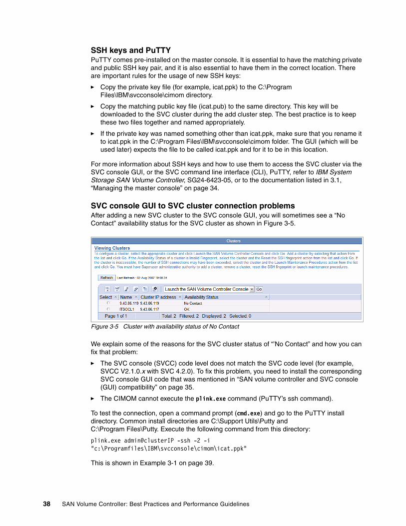
SSH keys and PuTTYPuTTY comes pre-installed on the master console. It is essential to have the matching private and public SSH key pair, and it is also essential to have them in the correct location. There are important rules for the usage of new SSH keys:
� Copy the private key file (for example, icat.ppk) to the C:\Program Files\IBM\svcconsole\cimom directory.
� Copy the matching public key file (icat.pub) to the same directory. This key will be downloaded to the SVC cluster during the add cluster step. The best practice is to keep these two files together and named appropriately.
� If the private key was named something other than icat.ppk, make sure that you rename it to icat.ppk in the C:\Program Files\IBM\svcconsole\cimom folder. The GUI (which will be used later) expects the file to be called icat.ppk and for it to be in this location.
For more information about SSH keys and how to use them to access the SVC cluster via the SVC console GUI, or the SVC command line interface (CLI), PuTTY, refer to IBM System Storage SAN Volume Controller, SG24-6423-05, or to the documentation listed in 3.1, “Managing the master console” on page 34.
SVC console GUI to SVC cluster connection problemsAfter adding a new SVC cluster to the SVC console GUI, you will sometimes see a “No Contact” availability status for the SVC cluster as shown in Figure 3-5.
Figure 3-5 Cluster with availability status of No Contact
We explain some of the reasons for the SVC cluster status of “’No Contact” and how you can fix that problem:
� The SVC console (SVCC) code level does not match the SVC code level (for example, SVCC V2.1.0.x with SVC 4.2.0). To fix this problem, you need to install the corresponding SVC console GUI code that was mentioned in “SAN volume controller and SVC console (GUI) compatibility” on page 35.
� The CIMOM cannot execute the plink.exe command (PuTTY’s ssh command).
To test the connection, open a command prompt (cmd.exe) and go to the PuTTY install directory. Common install directories are C:\Support Utils\Putty and C:\Program Files\Putty. Execute the following command from this directory:
plink.exe admin@clusterIP -ssh -2 -i "c:\Programfiles\IBM\svcconsole\cimom\icat.ppk"
This is shown in Example 3-1 on page 39.
38 SAN Volume Controller: Best Practices and Performance Guidelines

Example 3-1 Command execution
C:\Program Files\PuTTY>plink.exe [email protected] -ssh -2 -i "c:\Program files\IBM\svcconsole\cimom\icat.ppk"Using username "admin".Last login: Fri Jul 27 11:18:48 2007 from 9.43.86.115IBM_2145:ITSOCL1:admin>
In Example 3-1, we executed the command, and the connection is established. If the command fails, there are a few things we can check:
� The location of the PuTTY executable does not match the SSHCLI path in setupcmdline.bat.
� The icat.ppk key needs to be in the C:\Program Files\IBM\svcconsole\cimom directory.
� The icat.ppk file found in the C:\Program Files\IBM\svcconsole\cimom directory needs to match the icat.pub key uploaded to the SVC cluster.
� The CIMOM can execute the plink.exe command, but the SVC cluster does not exist, it is offline, or the network is down. Check if the SVC cluster is up and running (check the front panel of the SVC nodes and use the arrow keys on the node to determine if the Ethernet on the configuration node is up). Check your local Ethernet settings and issue a ping to the SVC cluster IP address.
If after you have performed all of these actions on the SVC cluster, and it is still in “No Contact” state, it is time to call IBM Support.
3.1.2 Managing multiple master consoles
In certain environments, it is important to have redundant management tools for the storage subsystems, host, and SAN, and this approach also applies to the master console.
Advantages of having more than one MC:
� Redundancy: If one master console is failing, you can still use the other master console to continue administering the SVC cluster.
� Manageability from multiple locations: If you have two separate master consoles in two different locations, you can manage them from both sites. For redundancy reasons, a primary SVC cluster might be located at one location, and a secondary cluster might be located at another location. The master console must also be available in both locations, and it might be beneficial to be able to manage both clusters.
� Managing different SVC code level versions: For some clients, it might be necessary to have a different version of the SVC console GUI running, because the clients are controlling two different versions of the SVC cluster and the cluster code.
Configuration considerationsFor managing two different master consoles, the same rules for managing a single master console apply as in 3.1.1, “Managing a single master console” on page 34. The only difference is that you have to provide different values for each master console:
� Machine name: A fully-qualified Domain Name Server (DNS) name for the master console
� Master console IP address: The address that will be used to access the master console
Note: The master console is the management tool for the SVC cluster. If the master console fails, the SVC cluster will still remain operational.
Chapter 3. Master console 39

� Gateway IP address: The default gateway IP address used by the master console
� Subnet mask: The subnet mask for the master console
Connection limitationsThe connection limitation of 10 will apply to both master consoles. Each master console will use up one SSH connection for each GUI session that is launched. The connection limit can be reached very quickly with multiple users of the same cluster.
One disadvantage of using two master consoles to manage two clusters is that if one cluster is currently not operational, for example “No Contact” for the SVC cluster state, ease of access to the other cluster is affected by the two minute timeout during the launch of SVC menus when the GUI is checking the status of both clusters.
This timeout appears while the SVC console GUI is trying to access the “missing” SVC cluster.
3.1.3 Administration roles
Role-based security commands are used to restrict the administrative abilities of a user. These commands consist of the mkauth command (to assign a specific role of CopyOperator or Administrator), the rmauth command (to revert the assigned role to the default Monitor role), and the lsauth command (to view entries in the Role-based Security authorization table).
The roles that are assigned by the mkauth command relate only to SSH sessions established with the SAN Volume Controller cluster using the admin user. The commands that you can initiate in an assigned role are determined by the role that is associated with the SSH key that established the session.
These are the user roles:
� Admin� Operator or CopyOperator� Service � Monitor
What are the different user rolesThe roles that are assigned by the mkauth command relate only to SSH sessions established with the SAN Volume Controller cluster using the admin user. The commands that you can initiate in an assigned role are determined by the role that is associated with the SSH key that established the session.
The User Monitor can run:
� All svcinfo commands � Selected svctask commands for error logs and dumps
The CopyOperator can manipulate (but not create):
� FlashCopy mappings and consistency groups� Metro Mirror and Global Mirror relationships and consistency groups
The existing users, Administrator and Service, are not changed.
Note: We do not discuss the Superuser here, because it has all possible rights.
40 SAN Volume Controller: Best Practices and Performance Guidelines

For more information about the command structure and the commands that each user role can use, refer to the SVC Controller Command-Line Interface User’s Guide, SC26-7903-01.
Creating a new user using the GUIIn the following section, we guide you through the steps to create a new user in a specific role using the SVC GUI. Having different user roles allows you to spread out workload or different operational tasks and assign them to multiple persons. This specific role only allows the user to use a certain set of commands on the SVC.
The steps to create a new user using the GUI are:
1. From the SAN Volume Controller Console, click Users. In the drop-down menu, choose Add a User. This is shown in Figure 3-6.
Figure 3-6 Add a new user
2. This panel provides you with information about setting up a new user role as shown in Figure 3-7.
Figure 3-7 Instructions to create a new user
3. This panel, Figure 3-8 on page 42, asks you to provide a new User Name and a new Password to be associated with this user.
Chapter 3. Master console 41
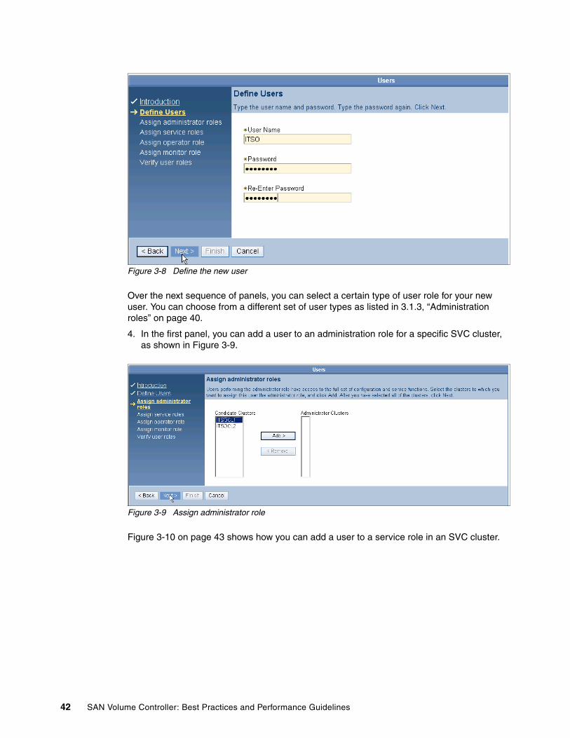
Figure 3-8 Define the new user
Over the next sequence of panels, you can select a certain type of user role for your new user. You can choose from a different set of user types as listed in 3.1.3, “Administration roles” on page 40.
4. In the first panel, you can add a user to an administration role for a specific SVC cluster, as shown in Figure 3-9.
Figure 3-9 Assign administrator role
Figure 3-10 on page 43 shows how you can add a user to a service role in an SVC cluster.
42 SAN Volume Controller: Best Practices and Performance Guidelines

Figure 3-10 Assign service role
Figure 3-11 shows how to add a user in the operator role to a corresponding SVC cluster.
Figure 3-11 Assign operator role
5. In Figure 3-12, we add a user in the monitor role to an SVC cluster.
Figure 3-12 Assign monitor role
6. In the last panel, Figure 3-13 on page 44, before finalizing the roles, you can review if the changes you are about to make are correct. At this stage, verify that the user is associated to the correct roles and clusters.
Chapter 3. Master console 43

Figure 3-13 Verify user roles
Create a new user using the CLIIn this section, we guide you through the steps to create a new user in a specific role using the CLI. Having different user roles allows you to spread out workload or different tasks of operation and assign them to multiple persons. This specific role will only allow the user to use a certain set of commands on the SVC.
The commands to administer the user roles are the mkauth command (to assign a specific role of CopyOperator or Administrator), the rmauth command (to revert the assigned role to the default Monitor role), and the lsauth command (to view entries in the Role-based Security authorization table). Furthermore, we need the svctask addsshkey to add a new user and the corresponding key.
The steps to create a new user using CLI are:
1. To add a user and the corresponding SSH key to a cluster, you must first copy the key file on the cluster to the /tmp directory using Secure Copy (SCP). Example 3-2 shows an SCP copy operation using PuTTY (PSCP).
Example 3-2 Copying a new icat.pub key to the SVC cluster using PSCP
C:\Program Files\PuTTY>pscp -load ITSOCL1 "C:\Program Files\IBM\MasterConsole\Support Utils\Putty\Thorsten\ticat.pub" [email protected]:/tmp/ticat.pub | 0 kB | 0.3 kB/s | ETA: 00:00:00 | 100%
2. After the new key is copied to the SVC cluster, you need to use the SVC CLI to manage the user roles. Before you add a new user, check the existing ssh keys on your SVC cluster by issuing the svcinfo lssshkeys -user all command. The output of this command, which is shown in Example 3-3, shows you the existing user IDs and keys. To add the new icat.pub key that you previously added via SCP, issue the command svctask addsshkey.
Example 3-3 Create a new user
IBM_2145:ITSOCL1:admin>svcinfo lssshkeys -user allid userid key_identifier1 admin admin
IBM_2145:ITSOCL1:admin>svctask addsshkey -user admin -file /tmp/ticat.pub -label testkey
IBM_2145:ITSOCL1:admin>svcinfo lssshkeys -user all
44 SAN Volume Controller: Best Practices and Performance Guidelines

id userid key_identifier1 admin admin2 admin test
3. When you run the svcinfo lssshkey again, you can see that a new user ID and key is added to the SVC cluster.
With the svctask mkauth command, you can change a user’s default authorization role from that of Monitor to either CopyOperator or Administrator. This is shown in Example 3-4.
Example 3-4 Changing the user role
IBM_2145:ITSOCL1:admin>svcinfo lsauthid ssh_label Role0 admin Administrator1 test Administrator
IBM_2145:ITSOCL1:admin>svctask mkauth -label test -role CopyOperator
IBM_2145:ITSOCL1:admin>svcinfo lsauthid ssh_label Role0 admin Administrator1 test CopyOperator
4. By using rmauth, the user will be assigned the default operation role, which is Monitor. Using mkauth, you can assign CopyOperator or Administrator again. This is shown in Example 3-5.
Example 3-5 Manage user roles
IBM_2145:ITSOCL1:admin>svcinfo lsauthid ssh_label Role0 admin Administrator1 test CopyOperator
IBM_2145:ITSOCL1:admin>svctask rmauth -label test
IBM_2145:ITSOCL1:admin>svcinfo lsauthid ssh_label Role0 admin Administrator1 test Monitor
IBM_2145:ITSOCL1:admin>svctask mkauth -label test -role Administrator
IBM_2145:ITSOCL1:admin>svcinfo lsauthid ssh_label Role0 admin Administrator1 test Administrator
This recently added user can now be used to log in via PuTTY. Open PuTTY and create a new session to your SVC cluster. For more information about how to use PuTTY, refer to IBM System Storage SAN Volume Controller, SG24-6423-05.
Click SSH → Auth (see Figure 3-14 on page 46) to select and use the SSH key that we added in Example 3-2 on page 44 and Example 3-3 on page 44 via the scp and addsshkey commands. Save this session. In Figure 3-14 on page 46, we give you an example of how to select and save the new SSH key to your PuTTY session.
Chapter 3. Master console 45
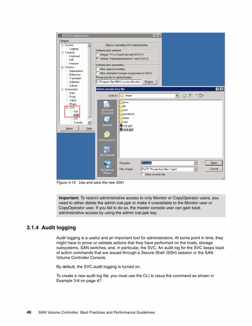
Figure 3-14 Use and save the new SSH
3.1.4 Audit logging
Audit logging is a useful and an important tool for administrators. At some point in time, they might have to prove or validate actions that they have performed on the hosts, storage subsystems, SAN switches, and, in particular, the SVC. An audit log for the SVC keeps track of action commands that are issued through a Secure Shell (SSH) session or the SAN Volume Controller Console.
By default, the SVC audit logging is turned on.
To create a new audit log file, you must use the CLI to issue the command as shown in Example 3-6 on page 47
Important: To restrict administrative access to only Monitor or CopyOperator users, you need to either delete the admin icat.ppk or make it unavailable to the Monitor user or CopyOperator user. If you fail to do so, the master console user can gain back administrative access by using the admin icat.ppk key.
46 SAN Volume Controller: Best Practices and Performance Guidelines
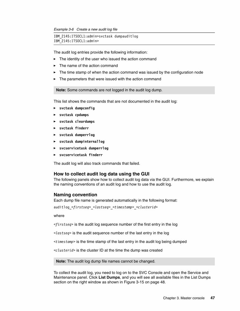
Example 3-6 Create a new audit log file
IBM_2145:ITSOCL1:admin>svctask dumpauditlogIBM_2145:ITSOCL1:admin>
The audit log entries provide the following information:
� The identity of the user who issued the action command
� The name of the action command
� The time stamp of when the action command was issued by the configuration node
� The parameters that were issued with the action command
This list shows the commands that are not documented in the audit log:
� svctask dumpconfig
� svctask cpdumps
� svctask cleardumps
� svctask finderr
� svctask dumperrlog
� svctask dumpinternallog
� svcservicetask dumperrlog
� svcservicetask finderr
The audit log will also track commands that failed.
How to collect audit log data using the GUIThe following panels show how to collect audit log data via the GUI. Furthermore, we explain the naming conventions of an audit log and how to use the audit log.
Naming conventionEach dump file name is generated automatically in the following format:
auditlog_<firstseq>_<lastseq>_<timestamp>_<clusterid>
where
<firstseq> is the audit log sequence number of the first entry in the log
<lastseq> is the audit sequence number of the last entry in the log
<timestamp> is the time stamp of the last entry in the audit log being dumped
<clusterid> is the cluster ID at the time the dump was created
To collect the audit log, you need to log on to the SVC Console and open the Service and Maintenance panel. Click List Dumps, and you will see all available files in the List Dumps section on the right window as shown in Figure 3-15 on page 48.
Note: Some commands are not logged in the audit log dump.
Note: The audit log dump file names cannot be changed.
Chapter 3. Master console 47
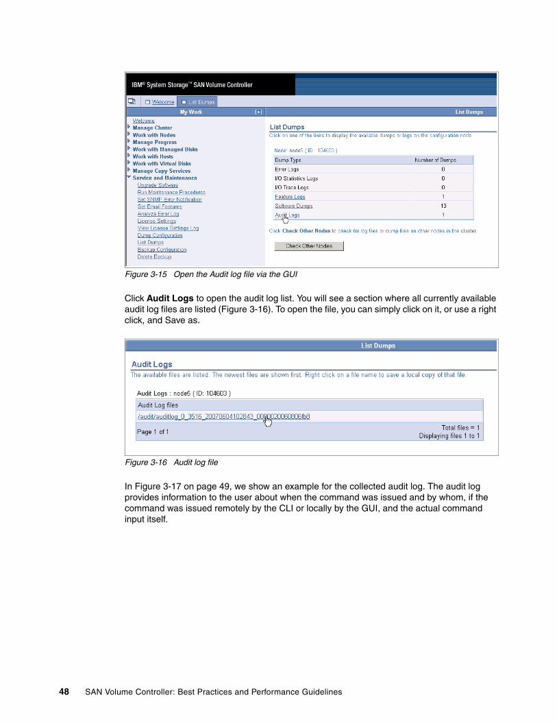
Figure 3-15 Open the Audit log file via the GUI
Click Audit Logs to open the audit log list. You will see a section where all currently available audit log files are listed (Figure 3-16). To open the file, you can simply click on it, or use a right click, and Save as.
Figure 3-16 Audit log file
In Figure 3-17 on page 49, we show an example for the collected audit log. The audit log provides information to the user about when the command was issued and by whom, if the command was issued remotely by the CLI or locally by the GUI, and the actual command input itself.
48 SAN Volume Controller: Best Practices and Performance Guidelines

Figure 3-17 Example for a captured audit log via GUI
How to collect audit log data using the CLIIn these examples, we show how to collect the audit log data via the CLI. We show how to take new audit log dumps, and we explain the output.
You can use the dumpauditlog (Example 3-7) command to reset or clear the contents of the in-memory audit log. The contents of the audit log are sent to a file in the /dumps/audit directory on the current configuration node.
Example 3-7 Dump a new audit log
IBM_2145:ITSOCL1:admin>svctask dumpauditlogIBM_2145:ITSOCL1:admin>
The lsauditlogdumps command generates a list of the audit log dumps that are available on the nodes in the cluster. After you have issued the command in Example 3-7, you will get a list of all available audit log dumps by typing the command shown in Example 3-8.
Example 3-8 List the available audit log files
IBM_2145:ITSOCL1:admin>svcinfo lsauditlogdumpsid auditlog_filename0 auditlog_0_3516_20070604102843_0000020060806fb81 auditlog_0_130_20070724115258_0000020060406fca
For the naming convention, refer to “Naming convention” on page 47.
In Example 3-9 on page 50, we show a captured audit log and a few entries in the logfile.
Chapter 3. Master console 49
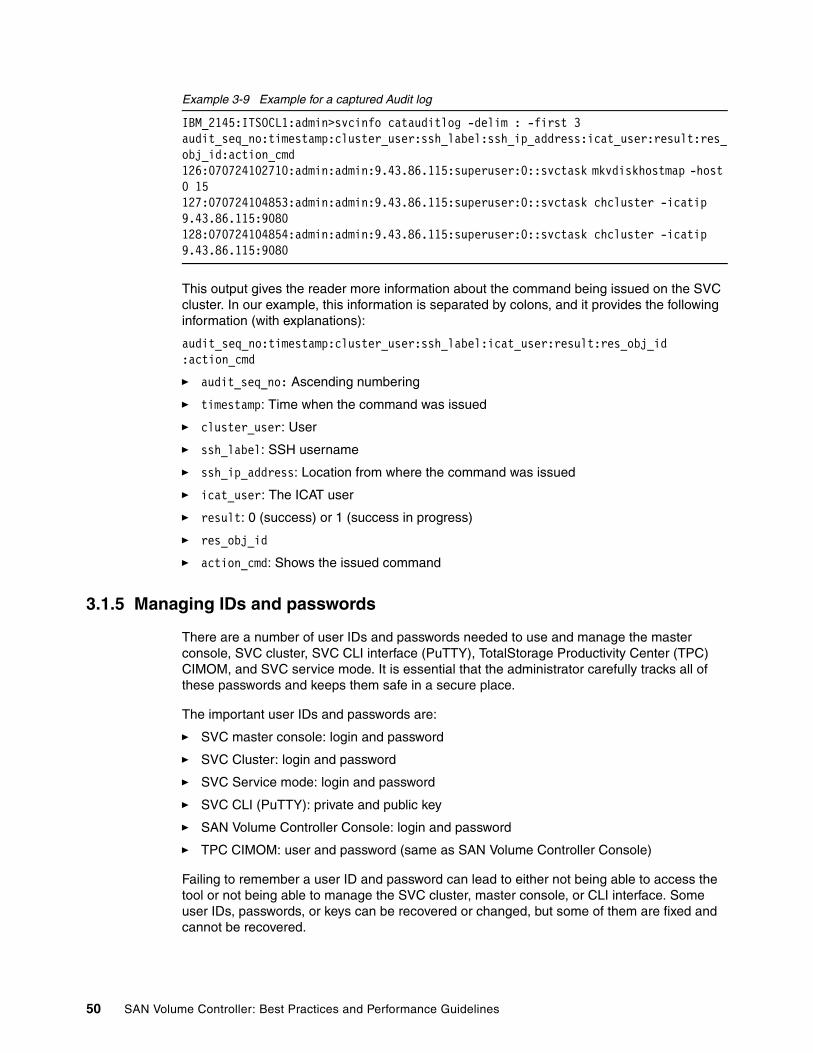
Example 3-9 Example for a captured Audit log
IBM_2145:ITSOCL1:admin>svcinfo catauditlog -delim : -first 3audit_seq_no:timestamp:cluster_user:ssh_label:ssh_ip_address:icat_user:result:res_obj_id:action_cmd126:070724102710:admin:admin:9.43.86.115:superuser:0::svctask mkvdiskhostmap -host 0 15127:070724104853:admin:admin:9.43.86.115:superuser:0::svctask chcluster -icatip 9.43.86.115:9080128:070724104854:admin:admin:9.43.86.115:superuser:0::svctask chcluster -icatip 9.43.86.115:9080
This output gives the reader more information about the command being issued on the SVC cluster. In our example, this information is separated by colons, and it provides the following information (with explanations):
audit_seq_no:timestamp:cluster_user:ssh_label:icat_user:result:res_obj_id:action_cmd
� audit_seq_no: Ascending numbering
� timestamp: Time when the command was issued
� cluster_user: User
� ssh_label: SSH username
� ssh_ip_address: Location from where the command was issued
� icat_user: The ICAT user
� result: 0 (success) or 1 (success in progress)
� res_obj_id
� action_cmd: Shows the issued command
3.1.5 Managing IDs and passwords
There are a number of user IDs and passwords needed to use and manage the master console, SVC cluster, SVC CLI interface (PuTTY), TotalStorage Productivity Center (TPC) CIMOM, and SVC service mode. It is essential that the administrator carefully tracks all of these passwords and keeps them safe in a secure place.
The important user IDs and passwords are:
� SVC master console: login and password
� SVC Cluster: login and password
� SVC Service mode: login and password
� SVC CLI (PuTTY): private and public key
� SAN Volume Controller Console: login and password
� TPC CIMOM: user and password (same as SAN Volume Controller Console)
Failing to remember a user ID and password can lead to either not being able to access the tool or not being able to manage the SVC cluster, master console, or CLI interface. Some user IDs, passwords, or keys can be recovered or changed, but some of them are fixed and cannot be recovered.
50 SAN Volume Controller: Best Practices and Performance Guidelines
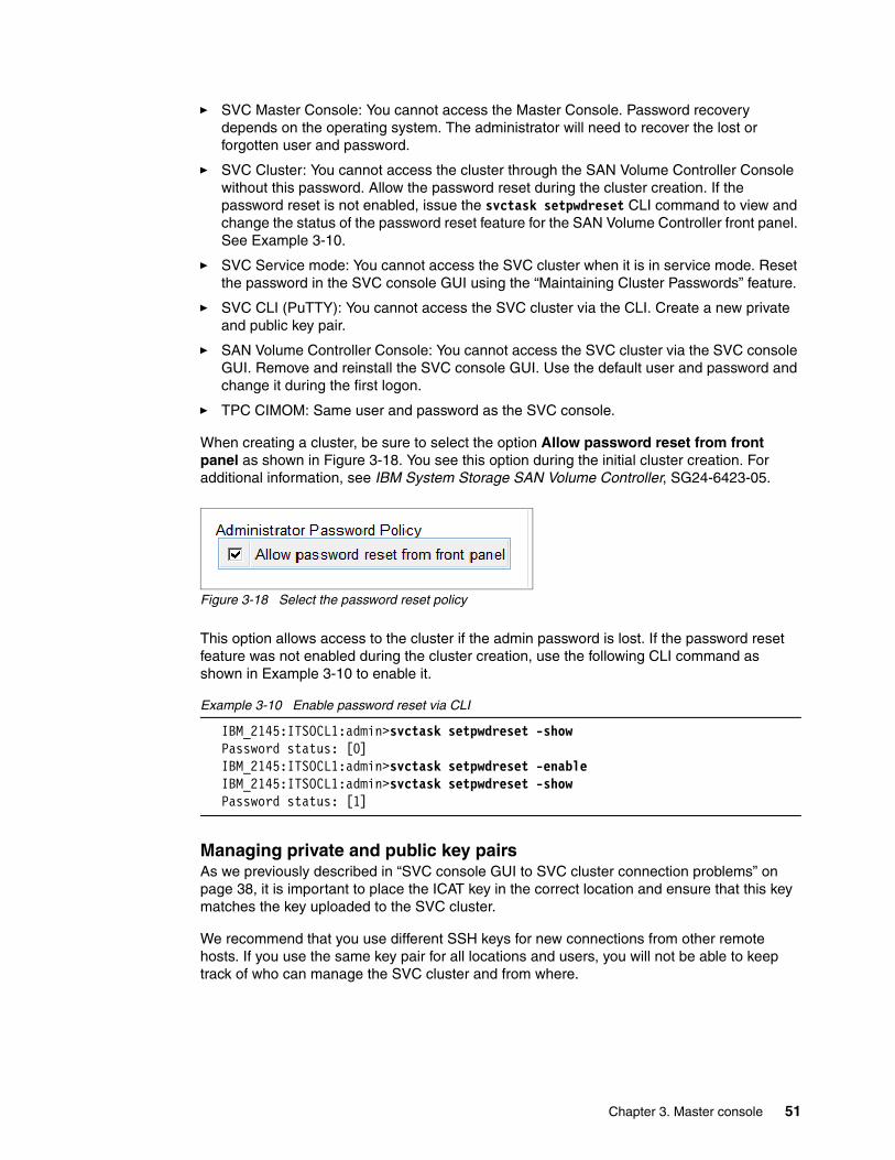
� SVC Master Console: You cannot access the Master Console. Password recovery depends on the operating system. The administrator will need to recover the lost or forgotten user and password.
� SVC Cluster: You cannot access the cluster through the SAN Volume Controller Console without this password. Allow the password reset during the cluster creation. If the password reset is not enabled, issue the svctask setpwdreset CLI command to view and change the status of the password reset feature for the SAN Volume Controller front panel. See Example 3-10.
� SVC Service mode: You cannot access the SVC cluster when it is in service mode. Reset the password in the SVC console GUI using the “Maintaining Cluster Passwords” feature.
� SVC CLI (PuTTY): You cannot access the SVC cluster via the CLI. Create a new private and public key pair.
� SAN Volume Controller Console: You cannot access the SVC cluster via the SVC console GUI. Remove and reinstall the SVC console GUI. Use the default user and password and change it during the first logon.
� TPC CIMOM: Same user and password as the SVC console.
When creating a cluster, be sure to select the option Allow password reset from front panel as shown in Figure 3-18. You see this option during the initial cluster creation. For additional information, see IBM System Storage SAN Volume Controller, SG24-6423-05.
Figure 3-18 Select the password reset policy
This option allows access to the cluster if the admin password is lost. If the password reset feature was not enabled during the cluster creation, use the following CLI command as shown in Example 3-10 to enable it.
Example 3-10 Enable password reset via CLI
IBM_2145:ITSOCL1:admin>svctask setpwdreset -showPassword status: [0]IBM_2145:ITSOCL1:admin>svctask setpwdreset -enableIBM_2145:ITSOCL1:admin>svctask setpwdreset -showPassword status: [1]
Managing private and public key pairsAs we previously described in “SVC console GUI to SVC cluster connection problems” on page 38, it is important to place the ICAT key in the correct location and ensure that this key matches the key uploaded to the SVC cluster.
We recommend that you use different SSH keys for new connections from other remote hosts. If you use the same key pair for all locations and users, you will not be able to keep track of who can manage the SVC cluster and from where.
Chapter 3. Master console 51

3.1.6 Saving the SVC configuration
The SVC configuration will be backed up every day at 01:00 AM depending on the time zone. There is no way to change the backup time setting on the SVC. In addition to the automated config.backup, it is possible to create a new backup by user intervention. You can either run the backup command on the SVC CLI or issue a config.backup from the SVC console GUI.
The SVC cluster maintain two copies of the configuration file:
� svc.config.backup.xml � svc.config.backup.bak
These backup files contain information about the current SVC configuration, such as the SVC cluster specific information: code level, name and IP address, amount of MDisk, MDiskgrp, VDisk, hosts, controllers, their naming conventions, and more.
The svc.config.backup.xml file is needed if the SVC cluster has suffered a major problem, and IBM Support has to rebuild the configuration structure. This configuration backup does not save the actual data.
Before making major changes on your SVC cluster, such as the SVC code updates, storage subsystem changes, or switch changes, we recommend that you create a new backup of the configuration.
Creating a new config.backup using the CLITo create a config.backup file from the SVC CLI, open PuTTY and run the command svcconfig backup as shown in Example 3-11.
Example 3-11 Running the svc configuration backup
IBM_2145:ITSOCL1:admin>svcconfig backup......CMMVC6130W Inter-cluster partnership fully_configured will not be restored..CMMVC6112W controller controller0 has a default name...CMMVC6112W mdisk mdisk1 has a default name................CMMVC6136W No SSH key file svc.config.admin.admin.keyCMMVC6136W No SSH key file svc.config.test.admin.keyCMMVC6136W No SSH key file svc.config.thorsten.admin.key......................................CMMVC6155I SVCCONFIG processing completed successfully
IBM_2145:ITSOCL1:admin>svcinfo ls2145dumpsid 2145_filename0 svc.config.cron.bak_node11..17 ups_log.a18 svc.config.backup.bak_Node-119 svc.config.backup.xml_Node-1
52 SAN Volume Controller: Best Practices and Performance Guidelines

Creating a config.backup using the GUITo create a config.backup file from the SVC console GUI, you must open the Service and maintenance panel and run the Backup Configuration task as shown in Figure 3-19.
Figure 3-19 Backing up the SVC configuration
As is the case for the CLI, a new svc.config.backup.xml_Node-1 will appear in the list dump section.
Automated configuration backup to the master consoleWe recommend that you periodically copy the config.backup files off of the SVC cluster and store them locally on the master console. There is a guideline available that explains how to set up an manual or scheduled task.
You can read about SVC Configuration Backup to the master console at:
http://www-1.ibm.com/support/docview.wss?rs=591&context=STPVGU&context=STPVFV&q1=pageant&uid=ssg1S1002175&loc=en_US&cs=utf-8&lang=en
This sample demonstrates how to perform configuration backup on a cluster and move the backup file or files to a master console. Automation of this task is also described.
3.1.7 Restoring the SVC cluster configuration
Do not attempt to restore the SVC configuration on your own. Call IBM Support and have them help you restore the configuration.
Make sure that all other components are working as expected. For more information about common errors, see Chapter 15, “Troubleshooting and diagnostics” on page 259.
If you are unsure about what to do, call IBM Support and let them help you collect the necessary data.
Chapter 3. Master console 53

54 SAN Volume Controller: Best Practices and Performance Guidelines

Chapter 4. I/O Groups and nodes
In this chapter, we discuss general I/O Groups and nodes.
4
© Copyright IBM Corp. 2008. All rights reserved. 55

4.1 Determining I/O Groups
TotalStorage Productivity Center (TPC) can help you monitor the CPU performance of each node in an I/O Group. CPU performance is related to I/O performance, and when the CPUs become consistently 70% busy, you must consider either:
� Adding more nodes to the cluster and moving part of the workload onto the new nodes
� Move some VDisk to another I/O Group if the other I/O Group is not busy
To see how busy your CPUs are, you can use the TPC performance report by selecting “CPU Utilization”.
Several of the activities that affect CPU utilization are:
� VDisk activity: The preferred node is responsible for I/Os for the VDisk and coordinates sending the I/Os to the alternate node. While both systems will exhibit similar CPU utilization, the preferred node is a little busier. To be precise, a preferred node is always responsible for the destaging of writes for VDisks that it owns. Therefore, skewing preferred ownership of VDisks toward one node in the I/O Group will lead to more destaging, and therefore, more work on that node.
� FlashCopy activity: Each node (of the flash copy source) maintains a copy of the bitmap; CPU utilization is similar.
� Mirror Copy activity: The preferred node is responsible for coordinating copy information to the target and also ensuring that the I/O Group is up-to-date with the copy progress information or change block information. As soon as Global Mirror is enabled, there is an additional 10% overhead on I/O work due to the buffering and general I/O overhead of performing asynchronous Peer-to-Peer Remote Copy (PPRC).
� Cache management.
4.2 Node shutdown and node failure
When one SVC node fails in an I/O Group, its partner node detects the failed node within 15 seconds (often a lot sooner).
When this occurs, the surviving node immediately sets the cache into write-through mode and commences destaging all outstanding unwritten I/Os to Fibre Channel disk. Depending on the cache size of the SVC node, the current workload, and the amount of outstanding I/Os, this activity can last a few minutes.
While there is one surviving node in the I/O Group, host I/O continues to be serviced as normal; however, any write I/Os are committed to disk before confirming to the host that the I/O has been accepted.
This procedure is also adopted during code upgrades. While software updates are applied, one node in the I/O Group shuts down to upgrade the software while the other node continues to service I/Os.
56 SAN Volume Controller: Best Practices and Performance Guidelines

4.2.1 Impact when running single node I/O Groups
We examined the impact of a node failure on the I/O throughput.
In this example, we used IOMeter on a Windows host to generate disk traffic for one hour. We ran the same test using four scenarios to get an idea of the change in performance during each of the scenarios:
� Test A: No SVC in the path and 70 GB coming from a DS4500
� Test B: SVC in the path and 70 GB image mode
� Test C: SVC in the path and 70 GB coming from two MDisks
� Test DL: SVC node failure and one node’s ports were disabled at the switch
Our aim was to see what the change in performance was when a node failed and we compared that to a test situation where SVC was not in the node path.
While the IOMeter test might not reflect a typical application workload, we tested the same size VDisk during each test run, which ensured that the change in performance was attributed to our different VDisk to host configuration.
IOMeter confirmed the results shown in Table 4-1, “IOMeter results” on page 57.
Table 4-1 IOMeter results
We used TPC to collect performance data for the SVC cluster while the tests ran.
Figure 4-1 on page 58 shows the CPU utilization while the 70 GB disk was managed by the SVC (tests B, C, and D). The blue line shows node 1, which was the preferred path for this VDisk.
Before we started test D, we disabled all the ports for node 1 on the switches to which it was connected, which resulted in node 1 going offline and node 2 now being used as the alternate path to this VDisk.
Note: If you plan to shut down a node as part of scheduled downtime while leaving the surviving node running, we recommend:
� Select a time when there is the least amount of write I/O to shut down your node, which ensures that the SVC cache contains the least amount of outstanding write I/Os that are yet to be destaged to disk.
� Shut down down your node and wait at least 10 minutes before you perform your scheduled work.
If there is a fatal failure to the surviving node before the cache has been fully destaged, you might lose any uncommitted write I/Os.
Test Throughput (MB/s) I/Os per second (IOPS)
Improvement
A 55.81 1785.81 Base line
B 70.48 2255.32 26.3%
C 76.48 2450.43 37.0%
D 67.70 2166.42 21.3%
Chapter 4. I/O Groups and nodes 57

There was no noticeable increase in CPU utilization in test B and test C. There was a slight reduction in CPU utilization when running test D.
Figure 4-1 SVC node CPU utilization during test runs
Node 3 and node 4 were not used during this test.
While there is a loss in performance when a node fails, and this test revealed our loss meant that we only saw 88.5% performance (when compared to our best result, which is the normal SVC usage configuration), we conclude that it was still 21.3% better than direct-attached.
4.3 Adding or upgrading SVC node hardware
If you have a cluster of six or fewer nodes of older hardware, and you have purchased new hardware, you can choose to either start a new cluster for the new hardware or add the new hardware to the old cluster. Both configurations are supported.
While both options are practical, we recommend that you add the new hardware to your existing cluster. This recommendation only is true if, in the short term, you are not scaling the environment beyond the capabilities of this cluster.
By utilizing the existing cluster, you maintain the benefit of managing just one cluster. Also, if you are using mirror copy services to the remote site, you might be able to continue to do so without having to add SVC nodes at the remote site.
You have a couple of choices to upgrade an existing cluster’s hardware. The choices depend on the size of the existing cluster.
58 SAN Volume Controller: Best Practices and Performance Guidelines

If your cluster has up to six nodes, you have these options available:
� Add the new hardware to the cluster, migrate VDisks to the new nodes, and then retire the older hardware when it is no longer managing any VDisks.
This method requires a brief outage to the hosts to change the I/O Group for each VDisk.
� Swap out one node in each I/O Group at a time and replace it with the new hardware. We recommend that you engage an IBM Service Support Representative (SSR) to help you with this process.
You can perform this swap without an outage to the hosts.
If your cluster has eight nodes, the options are similar:
� Swap out a node in each I/O Group one at a time and replace it with the new hardware. We recommend that you engage an IBM SSR to help you with this process.
You can perform this swap without an outage to the hosts, and you need to swap a node in one I/O Group at a time. Do not change all I/O Groups in a multi-I/O Group cluster at one time.
� Move the VDisks to another I/O Group so that all VDisks are on three of the four I/O Groups. You can then remove the remaining I/O Group with no VDisks from the cluster and add the new hardware to the cluster.
As each pair of new nodes is added, VDisks can then be moved to the new nodes, leaving another old I/O Group pair that can be removed. After all the old pairs are removed, the last two new nodes can be added, and if required, VDisks can be moved onto them.
Unfortunately, this method requires several outages to the host, because VDisks are moved between I/O Groups. This method might not be practical unless you need to implement the new hardware over an extended period of time, and the first option is not practical for your environment.
� You can mix the previous two options.
New SVC hardware provides considerable performance benefits on each release, and there have been substantial performance improvements since the first hardware release.
Depending on the age of your existing SVC hardware, the performance requirements might be met by only six or fewer nodes of the new hardware.
If this is the case, you might be able to utilize a mix of the previous two steps. For example, use an IBM SSR to help you upgrade one or two I/O Groups, and then move the VDisks from the remaining I/O Groups onto the new hardware.
Chapter 4. I/O Groups and nodes 59

60 SAN Volume Controller: Best Practices and Performance Guidelines

Chapter 5. Storage controller
In this chapter, we discuss the following topics:
� Controller affinity and preferred path
� Pathing considerations for EMC Symmetrix/DMX and HDS
� Logical unit number (LUN) ID to MDisk translation
� MDisk to VDisk mapping
� Mapping physical logical block addresses (LBAs) to extents
� Media error logging
� Selecting array and cache parameters
� Considerations for controller configuration
� LUN masking
� Worldwide port name (WWPN) to physical port translation
� Using TotalStorage Productivity Center (TPC) to identify storage controller boundaries
� Using TPC to measure storage controller performance
5
© Copyright IBM Corp. 2008. All rights reserved. 61

5.1 Controller affinity and preferred path
In this section, we describe the architectural differences between common storage subsystems in terms of controller “affinity” (also referred to as preferred controller) and “preferred path”. In this context, affinity refers to the controller in a dual-controller subsystem that has been assigned access to the back-end storage for a specific LUN under nominal conditions (that is to say, both controllers are active). Preferred path refers to the host side connections that are physically connected to the controller that has the assigned affinity for the corresponding LUN being accessed.
All storage subsystems that incorporate a dual-controller architecture for hardware redundancy employ the concept of “affinity”. For example, if a subsystem has 100 LUNs, 50 of them have an affinity to controller 0, and 50 of them have an affinity to controller 1. This means that only one controller is serving any specific LUN at any specific instance in time; however, the aggregate workload for all LUNs is evenly spread across both controllers. This relationship exists during normal operation; however, each controller is capable of controlling all 100 LUNs in the event of a controller failure.
For the DS4000 and DS6000, preferred path is important, because Fibre Channel cards are integrated into the controller. This architecture allows “dynamic” multipathing and “active/standby” pathing through Fibre Channel cards that are attached to the same controller (the SVC does not support dynamic multipathing) and an alternate set of paths that are configured to the other controller that will be used if the corresponding controller fails.
For example, if each controller is attached to hosts through two Fibre Channel ports, 50 LUNs will use the two Fibre Channel ports in controller 0, and 50 will use the two Fibre Channel ports in controller 1. If either controller fails, the multipathing driver will fail the 50 LUNs associated with the failed controller over to the other controller and all 100 LUNs will use the two ports in the remaining controller. The DS4000 differs from the DS6000 and DS8000, because it has the capability to transfer ownership of LUNs at the LUN level as opposed to the controller level.
For the DS8000 and the Enterprise Storage Server® (ESS), the concept of preferred path is not used, because Fibre Channel cards are outboard of the controllers, and therefore, all Fibre Channel ports are available to access all LUNs regardless of cluster affinity. While cluster affinity still exists, the network between the outboard Fibre Channel ports and the controllers performs the appropriate controller “routing” as opposed to the DS4000 and DS6000 where controller routing is performed by the multipathing driver in the host, such as with IBM Subsystem Device Driver (SDD) and Redundant Disk Array Controller (RDAC).
5.1.1 ADT for DS4000
The DS4000 has a feature called Auto Logical Drive Transfer (ADT). This feature allows logical drive level failover as opposed to controller level failover. When you enable this option, the DS4000 moves LUN ownership between controllers according to the path used by the host.
For the SVC, the ADT feature is enabled by default when you select the “IBM TS SAN VCE” host type when you configure the DS4000.
Note: It is important that you select the “IBM TS SAN VCE” host type when configuring the DS4000 for SVC attachment in order to allow the SVC to properly manage the back-end paths.
62 SAN Volume Controller: Best Practices and Performance Guidelines

See Chapter 15, “Troubleshooting and diagnostics” on page 259 for information regarding checking the back-end paths to storage controllers.
5.1.2 Ensuring path balance prior to MDisk discovery
It is important that LUNs are properly balanced across storage controllers prior to performing MDisk discovery. Failing to do so can result in a suboptimal pathing configuration to the back-end disks, which can cause a performance degradation. Ensure that storage subsystems are in a dual-active state and that all LUNs have been distributed to their preferred controller (local affinity) prior to performing MDisk discovery. Pathing can always be rebalanced later, however, often not until after lengthy problem isolation has taken place.
If you discover that the LUNs are not evenly distributed across the dual controllers in a DS4000, you can dynamically change the LUN affinity. However, the SVC will move them back to the original controller, and the DS4000 will generate an error indicating that the LUN is no longer on its preferred controller. To correct this situation, you need to run the SVC command svctask detectmdisk or use the GUI option “Discover MDisks”. SVC will requery the DS4000 and access the LUNs via the new preferred controller configuration.
5.2 Pathing considerations for EMC Symmetrix/DMX and HDS
There are certain storage controller types that present a unique worldwide node name (WWNN) and worldwide port name (WWPN) for each port. This action can cause problems when attached to the SVC, because the SVC enforces a WWNN maximum of four per storage controller.
Because of this behavior, you must be sure to group the ports if you want to connect more than four target ports to an SVC. Refer to the IBM System Storage SAN Volume Controller Software Installation and Configuration Guide Version 4.2.0, SC23-6628-00, for instructions.
5.3 LUN ID to MDisk translation
The “Controller LUN Number” for MDisks is returned from the storage controllers in the “Report LUNs Data”. The following sections show how to decode the LUN ID from the report LUNs data for storage controllers ESS, DS6000, and DS8000.
5.3.1 ESS
The ESS uses 14 bits to represent the LUN ID, which decodes as:
XXXX00000000 = xxyyXXX = 14 bit LUN ID
The first two bits (xx) are always set to 01.
The second two bits (yy) are not used.
For example, LUN ID 1723, as displayed from the ESS storage specialist, displays as 572300000000 in the “Controller LUN Number” field on SVC from the MDisk details:
572300000000 = ‘0101’ 723 = 1723
Chapter 5. Storage controller 63

5.3.2 DS6000 and DS8000
The DS6000 and DS8000 use 16 bits to represent the LUN ID, which decodes as:
40XX40XX0000 = XXXX = 16 bit LUN ID
The LUN ID will only uniquely identify LUNs within the same storage controller. If multiple storage devices are attached to the same SVC cluster, the LUN ID needs to be combined with the WWNN attribute in order to uniquely identify LUNs within the SVC cluster. The SVC does not contain an attribute to identify the storage controller serial number; however, the Controller Name field can be used for this purpose and will simplify the LUN ID to MDisk translation.
The Controller Name field is populated with a default value at the time that the storage controller is initially configured to the SVC cluster. You must modify this field by using the SVC console selections: Work with Managed Disk → Disk Storage Controller → Rename a Disk Controller System.
Figure 5-1 shows LUN ID fields that are displayed from the DS8000 Storage Manager. LUN ID 1105, for example, appears as 401140050000 in the Controller LUN Number field on the SVC, which is shown in Figure 5-2 on page 65.
Figure 5-1 Real-time manager
Best Practice: Include the storage controller serial number in the naming convention for the Controller Name field. For example, use DS8kABCDE for serial number 75-ABCDE.
64 SAN Volume Controller: Best Practices and Performance Guidelines
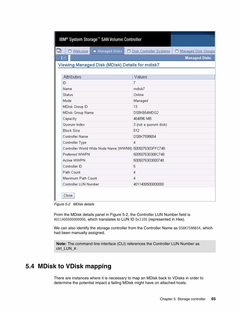
Figure 5-2 MDisk details
From the MDisk details panel in Figure 5-2, the Controller LUN Number field is 4011400500000000, which translates to LUN ID 0x1105 (represented in Hex).
We can also identify the storage controller from the Controller Name as DS8K7598654, which had been manually assigned.
5.4 MDisk to VDisk mapping
There are instances where it is necessary to map an MDisk back to VDisks in order to determine the potential impact a failing MDisk might have on attached hosts.
Note: The command line interface (CLI) references the Controller LUN Number as ctrl_LUN_#.
Chapter 5. Storage controller 65
You can use the lsvdiskextent CLI command to obtain this information.
The lsmdiskextent output in Example 5-1 shows a list of VDisk IDs that have extents allocated to mdisk0 along with the number of extents. The GUI also has a drop-down option to perform the same function for VDisks and MDisks.
Example 5-1 lsmdiskextent
IBM_2123:ITSOCL1:admin>svcinfo lsmdiskextent mdisk0id number_of_extents1 169 4019 2021 20IBM 2145:ITSOCL1:admin>
5.5 Mapping physical LBAs to Extents
At the time of writing this book, mapping physical LBAs to VDisk extents is not a trivial endeavor, and it is only possible with help from SVC development. This might change in future versions of SVC where this function might be made available to the user.
Instances where this translation is desirable are in cases where media errors have been reported by the back-end storage controller, but VDisks have not yet been impacted. In this case, it becomes important to know how these data checks will affect host applications so that you can perform the appropriate recovery actions.
If this translation is required, you must contact technical support for assistance with collecting a dump and ask that the call is escalated to SVC development. SVC development will require the dump in order to perform the mapping.
5.6 Media error logging
Media errors on back-end MDisks can be encountered by Host I/O and by SVC background functions, such as VDisk migration and FlashCopy. In this section, we describe the detailed sense data for media errors presented to the host and SVC.
5.6.1 Host encountered media errors
Data checks encountered on a VDisk from a host read request will return check condition status with Key/Code/Qualifier = 030000.
Example 5-2 shows an example of the detailed sense data returned to an AIX host for an unrecoverable media error.
Example 5-2 Sense data
LABEL: SC_DISK_ERR2IDENTIFIER: B6267342
Date/Time: Thu Jul 5 10:49:35 2007Sequence Number: 4334
66 SAN Volume Controller: Best Practices and Performance Guidelines
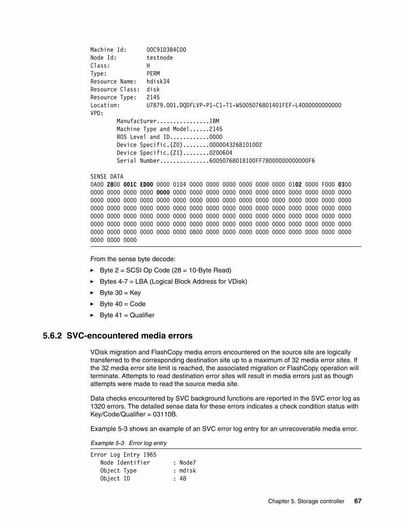
Machine Id: 00C91D3B4C00Node Id: testnodeClass: HType: PERMResource Name: hdisk34Resource Class: diskResource Type: 2145Location: U7879.001.DQDFLVP-P1-C1-T1-W5005076801401FEF-L4000000000000VPD: Manufacturer................IBM Machine Type and Model......2145 ROS Level and ID............0000 Device Specific.(Z0)........0000043268101002 Device Specific.(Z1)........0200604 Serial Number...............60050768018100FF78000000000000F6
SENSE DATA0A00 2800 001C ED00 0000 0104 0000 0000 0000 0000 0000 0000 0102 0000 F000 0300 0000 0000 0000 0000 0000 0000 0000 0000 0000 0000 0000 0000 0000 0000 0000 0000 0000 0000 0000 0000 0000 0000 0000 0000 0000 0000 0000 0000 0000 0000 0000 0000 0000 0000 0000 0000 0000 0000 0000 0000 0000 0000 0000 0000 0000 0000 0000 0000 0000 0000 0000 0000 0000 0000 0000 0000 0000 0000 0000 0000 0000 0000 0000 0000 0000 0000 0000 0000 0000 0000 0000 0000 0000 0000 0000 0000 0000 0000 0000 0000 0000 0000 0000 0000 0000 0000 0800 0000 0000 0000 0000 0000 0000 0000 0000 0000 0000 0000 0000
From the sense byte decode:
� Byte 2 = SCSI Op Code (28 = 10-Byte Read)
� Bytes 4-7 = LBA (Logical Block Address for VDisk)
� Byte 30 = Key
� Byte 40 = Code
� Byte 41 = Qualifier
5.6.2 SVC-encountered media errors
VDisk migration and FlashCopy media errors encountered on the source site are logically transferred to the corresponding destination site up to a maximum of 32 media error sites. If the 32 media error site limit is reached, the associated migration or FlashCopy operation will terminate. Attempts to read destination error sites will result in media errors just as though attempts were made to read the source media site.
Data checks encountered by SVC background functions are reported in the SVC error log as 1320 errors. The detailed sense data for these errors indicates a check condition status with Key/Code/Qualifier = 03110B.
Example 5-3 shows an example of an SVC error log entry for an unrecoverable media error.
Example 5-3 Error log entry
Error Log Entry 1965 Node Identifier : Node7 Object Type : mdisk Object ID : 48
Chapter 5. Storage controller 67

Sequence Number : 7073 Root Sequence Number : 7073 First Error Timestamp : Thu Jul 26 17:44:13 2007 : Epoch + 1185486253 Last Error Timestamp : Thu Jul 26 17:46:13 2007 : Epoch + 1185486373 Error Count : 21
Error ID : 10025 : A media error has occurred during I/O to a Managed Disk Error Code : 1320 : Disk I/O medium error Status Flag : FIXED Type Flag : TRANSIENT ERROR 40 11 40 02 00 00 00 00 00 00 00 02 28 00 58 59 6D 80 00 00 40 00 00 00 00 00 00 00 00 00 80 00 04 02 00 02 00 00 00 00 00 01 0A 00 00 80 00 00 02 03 11 0B 80 6D 59 58 00 00 00 00 08 00 C0 AA 00 00 00 00 00 00 00 00 00 00 00 00 00 00 00 00 00 00 00 00 00 00 00 00 00 00 00 00 00 00 00 00 00 00 00 00 00 00 00 00 00 00 00 00 00 00 00 00 00 00 00 00 0B 00 00 00 04 00 00 00 10 00 02 01
Where the sense byte decodes as:
� Byte 12 = SCSI Op Code (28 = 10-Byte Read)
� Bytes 14-17 = LBA (Logical Block Address for MDisk)
� Bytes 49-51 = Key/Code/Qualifier
5.7 Selecting array and cache parameters
In this section, we describe the optimum array and cache parameters.
5.7.1 DS4000 array width
With RAID5 arrays, the number of physical drives to put into an array always presents a compromise. Striping across a larger number of drives can improve performance for transaction-based workloads. However, striping can also have a negative effect on sequential
Caution: Attempting to locate data checks on MDisks by scanning VDisks with host applications, such as dd, or using SVC background functions, such as VDisk migrations and FlashCopy, can cause the Managed Disk Group (MDG) to go offline as a result of error handling behavior in current levels of SVC microcode. This behavior will change in future levels of SVC microcode. Check with support prior to attempting to locate data checks by any of these means.
Notes:
� Media errors encountered on VDisks will log error code 1320 “Disks I/O Medium Error”.
� VDisk migrations and flashcopies that exceed the media error site limit of 32 will terminate and log error code 1610 “Too many medium errors on Managed Disk”.
68 SAN Volume Controller: Best Practices and Performance Guidelines

workloads. A common mistake that people make when selecting array width is the tendency to focus only on the capability of a single array to perform various workloads. However, you must also consider in this decision the aggregate throughput requirements of the entire storage server. A large number of physical disks in an array can create a workload imbalance between the controllers, because only one controller of the DS4000 actively accesses a specific array.
When selecting array width, you must also consider its effect on rebuild time and availability.
A larger number of disks in an array increases the rebuild time for disk failures, which can have a negative effect on performance. Additionally, more disks in an array increases the probability of having a second drive fail within the same array prior to the rebuild completion of an initial drive failure, which is an inherent exposure to the RAID5 architecture.
5.7.2 Segment size
With direct-attached hosts, considerations are often made to align device data partitions to physical drive boundaries within the storage controller. For the SVC, this is less critical based on the caching that it provides and the fact that there is less variation in its I/O profile, which is used to access back-end disks.
Because the maximum destage size for the SVC is 32 KB, it is not possible to achieve full stride writes for random workloads. For the SVC, the only opportunity for full stride writes occurs with large sequential workloads, and in that case, the larger the segment size is, the better. Larger segment sizes can adversely affect random I/O, however. The SVC and controller cache do a good job of hiding the RAID5 write penalty for random I/O, and therefore, larger segment sizes can be accommodated. The main consideration for selecting segment size is to ensure that a single host I/O will fit within a single segment to prevent accessing multiple physical drives.
Testing has shown that the best compromise for handling all workloads is to use a segment size of 256k.
Cache block sizeThe DS4000 uses a 4k cache block size by default; however, it can be changed to 16k.
For the earlier models of DS4000 using the 2 Gb FC adapters, the 4k block size performed better for random I/O, and 16k performs better for sequential I/O. However, because most workloads contain a mix of random and sequential I/O, the default values have proven to be the best choice. For the higher performing DS4700 and DS4800, the 4k block size advantage for random I/O has become harder to see. Because most client workloads involve at least some sequential workload, the best overall choice for these models is the 16k block size.
Best practice: For the DS4000, we recommend array widths of 4+p and 8+p.
Best practice: We recommend a segment size of 256k as the best compromise for all workloads.
Best practice:
� For the DS4000, leave the cache block size at the default value of 4k.
� For the DS4700 and DS4800 models, set the cache block size to 16k.
Chapter 5. Storage controller 69
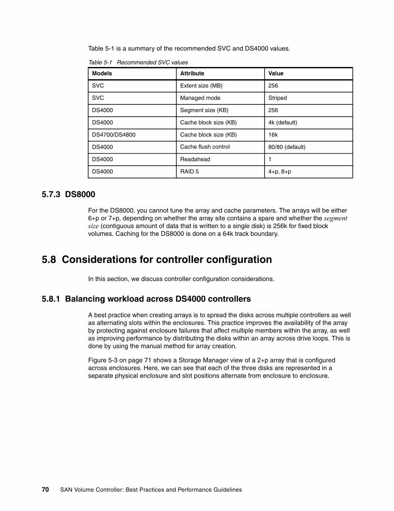
Table 5-1 is a summary of the recommended SVC and DS4000 values.
Table 5-1 Recommended SVC values
5.7.3 DS8000
For the DS8000, you cannot tune the array and cache parameters. The arrays will be either 6+p or 7+p, depending on whether the array site contains a spare and whether the segment size (contiguous amount of data that is written to a single disk) is 256k for fixed block volumes. Caching for the DS8000 is done on a 64k track boundary.
5.8 Considerations for controller configuration
In this section, we discuss controller configuration considerations.
5.8.1 Balancing workload across DS4000 controllers
A best practice when creating arrays is to spread the disks across multiple controllers as well as alternating slots within the enclosures. This practice improves the availability of the array by protecting against enclosure failures that affect multiple members within the array, as well as improving performance by distributing the disks within an array across drive loops. This is done by using the manual method for array creation.
Figure 5-3 on page 71 shows a Storage Manager view of a 2+p array that is configured across enclosures. Here, we can see that each of the three disks are represented in a separate physical enclosure and slot positions alternate from enclosure to enclosure.
Models Attribute Value
SVC Extent size (MB) 256
SVC Managed mode Striped
DS4000 Segment size (KB) 256
DS4000 Cache block size (KB) 4k (default)
DS4700/DS4800 Cache block size (KB) 16k
DS4000 Cache flush control 80/80 (default)
DS4000 Readahead 1
DS4000 RAID 5 4+p, 8+p
70 SAN Volume Controller: Best Practices and Performance Guidelines

Figure 5-3 Storage Manager
5.8.2 Balancing workload across DS8000 controllers
When configuring storage on the DS8000, it is important to ensure that ranks on a device adapter (DA) pair are evenly balanced between odd and even extent pools. Failing to do this can result in a considerable performance degradation due to uneven device adapter loading.
The DS8000 assigns server affinity to ranks when they are added to an extent pool. Ranks that belong to an even extent pool have an affinity to server0, and ranks that belong to an odd extent pool have an affinity to server1.
Figure 5-4 on page 72 shows an example of a configuration that will result in a 50% reduction in available bandwidth. Notice how arrays on each of the DA pairs are only being accessed by one of the adapters. In this case, all ranks on DA pair 0 have been added to even extent pools, which means that they all have an affinity to server0, and therefore, the adapter in server1 is sitting idle. Because this condition holds for all four DA pairs, only half of the adapters are actively performing work. This condition can also occur on a subset of the configured DA pairs.
Chapter 5. Storage controller 71

Figure 5-4 DA incorrect configuration
Example 5-4 shows what this invalid configuration looks like from the CLI output of the lsarray and lsrank commands. Notice that arrays residing on the same DA pair contain the same group number (0 or 1).
Example 5-4 Command output
dscli> lsarray -lDate/Time: Aug 8, 2007 8:54:58 AM CEST IBM DSCLI Version:5.2.410.299 DS: IBM.2107-75L2321Array State Data RAID type arsite Rank DA Pair DDMcap(10^9B) diskclass===================================================================================A0 Assign Normal 5 (6+P+S) S1 R0 0 146.0 ENTA1 Assign Normal 5 (6+P+S) S9 R1 1 146.0 ENTA2 Assign Normal 5 (6+P+S) S17 R2 2 146.0 ENTA3 Assign Normal 5 (6+P+S) S25 R3 3 146.0 ENTA4 Assign Normal 5 (6+P+S) S2 R4 0 146.0 ENTA5 Assign Normal 5 (6+P+S) S10 R5 1 146.0 ENTA6 Assign Normal 5 (6+P+S) S18 R6 2 146.0 ENTA7 Assign Normal 5 (6+P+S) S26 R7 3 146.0 ENT
dscli> lsrank -lDate/Time: Aug 8, 2007 8:52:33 AM CEST IBM DSCLI Version: 5.2.410.299 DS: IBM.2107-75L2321ID Group State datastate Array RAIDtype extpoolID extpoolnam stgtype exts usedexts======================================================================================R0 0 Normal Normal A0 5 P0 extpool0 fb 779 779R1 1 Normal Normal A1 5 P1 extpool1 fb 779 779R2 0 Normal Normal A2 5 P2 extpool2 fb 779 779R3 1 Normal Normal A3 5 P3 extpool3 fb 779 779R4 0 Normal Normal A4 5 P4 extpool4 fb 779 779R5 1 Normal Normal A5 5 P5 extpool5 fb 779 779R6 0 Normal Normal A6 5 P6 extpool6 fb 779 779R7 1 Normal Normal A7 5 P7 extpool7 fb 779 779
Figure 5-5 on page 73 shows an example of a correct configuration that balances the workload across all eight DA adapters.
72 SAN Volume Controller: Best Practices and Performance Guidelines

Figure 5-5 DA correct configuration
Example 5-5 shows what this correct configuration looks like from the CLI output of the lsrank command. The configuration from the lsarray output remains unchanged. Notice that arrays residing on the same DA pair are split between groups 0 and 1.
Example 5-5 Command output
dscli> lsrank -lDate/Time: Aug 9, 2007 2:23:18 AM CEST IBM DSCLI Version: 5.2.410.299 DS: IBM.2107-75L2321ID Group State datastate Array RAIDtype extpoolID extpoolnam stgtype exts usedexts======================================================================================R0 0 Normal Normal A0 5 P0 extpool0 fb 779 779R1 1 Normal Normal A1 5 P1 extpool1 fb 779 779R2 0 Normal Normal A2 5 P2 extpool2 fb 779 779R3 1 Normal Normal A3 5 P3 extpool3 fb 779 779R4 1 Normal Normal A4 5 P5 extpool5 fb 779 779R5 0 Normal Normal A5 5 P4 extpool4 fb 779 779R6 1 Normal Normal A6 5 P7 extpool7 fb 779 779R7 0 Normal Normal A7 5 P6 extpool6 fb 779 779
5.8.3 DS8000 ranks/extent pools
When configuring the DS8000, it is a best practice to place each rank in its own extent pool. This provides the best control for volume creation, because it ensures that all volume allocation from the selected extent pool will come from the same rank. Note that at the time of writing this book, the DS8000 does not have the ability to stripe volume allocation across multiple ranks. Therefore, the ability to concatenate volumes is the only capability gained from having multiple ranks per extent pool. The ability to concatenate volumes is only a benefit when you require volume sizes that exceed the capacity of a single array.
Best practice: Configure one rank per extent pool.
Chapter 5. Storage controller 73
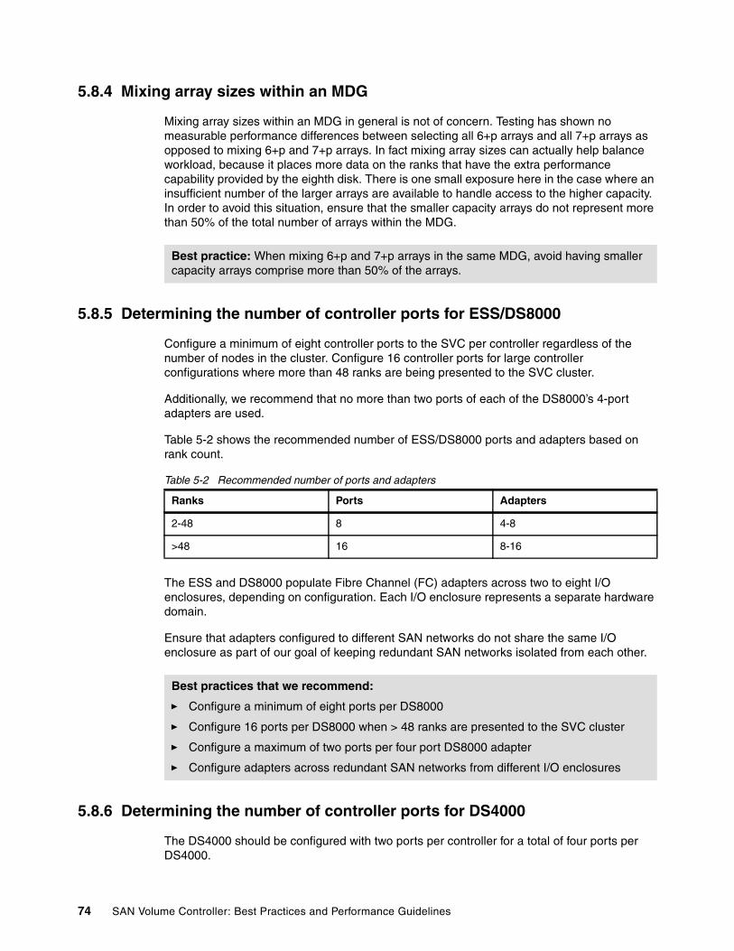
5.8.4 Mixing array sizes within an MDG
Mixing array sizes within an MDG in general is not of concern. Testing has shown no measurable performance differences between selecting all 6+p arrays and all 7+p arrays as opposed to mixing 6+p and 7+p arrays. In fact mixing array sizes can actually help balance workload, because it places more data on the ranks that have the extra performance capability provided by the eighth disk. There is one small exposure here in the case where an insufficient number of the larger arrays are available to handle access to the higher capacity. In order to avoid this situation, ensure that the smaller capacity arrays do not represent more than 50% of the total number of arrays within the MDG.
5.8.5 Determining the number of controller ports for ESS/DS8000
Configure a minimum of eight controller ports to the SVC per controller regardless of the number of nodes in the cluster. Configure 16 controller ports for large controller configurations where more than 48 ranks are being presented to the SVC cluster.
Additionally, we recommend that no more than two ports of each of the DS8000’s 4-port adapters are used.
Table 5-2 shows the recommended number of ESS/DS8000 ports and adapters based on rank count.
Table 5-2 Recommended number of ports and adapters
The ESS and DS8000 populate Fibre Channel (FC) adapters across two to eight I/O enclosures, depending on configuration. Each I/O enclosure represents a separate hardware domain.
Ensure that adapters configured to different SAN networks do not share the same I/O enclosure as part of our goal of keeping redundant SAN networks isolated from each other.
5.8.6 Determining the number of controller ports for DS4000
The DS4000 should be configured with two ports per controller for a total of four ports per DS4000.
Best practice: When mixing 6+p and 7+p arrays in the same MDG, avoid having smaller capacity arrays comprise more than 50% of the arrays.
Ranks Ports Adapters
2-48 8 4-8
>48 16 8-16
Best practices that we recommend:
� Configure a minimum of eight ports per DS8000
� Configure 16 ports per DS8000 when > 48 ranks are presented to the SVC cluster
� Configure a maximum of two ports per four port DS8000 adapter
� Configure adapters across redundant SAN networks from different I/O enclosures
74 SAN Volume Controller: Best Practices and Performance Guidelines

5.9 LUN masking
All SVC nodes must see the same set of LUNs from all target ports that have logged into the SVC nodes. If target ports are visible to the nodes that do not have the same set of LUNs assigned, SVC treats this situation as an error condition and generates error code 1625.
Validating the LUN masking from the storage controller and then confirming the correct path count from within the SVC is critical.
Example 5-6 shows four LUNs being presented from a DS8000 storage controller to a 4-node SVC cluster.
The DS8000 performs LUN masking based on volume group. Example 5-6 shows showvolgrp output for volume group V0, which contains four LUNs.
Example 5-6 showvolgrp output
dscli> showvolgrp -dev IBM.2107-75ALNN1 V0Date/Time: August 15, 2007 10:12:33 AM PDT IBM DSCLI Version: 5.0.4.43 DS: IBM.2107-75ALNN1Name SVCVG0ID V0Type SCSI MaskVols 1000 1001 1004 1005
Example 5-7 shows lshostconnect output from the DS8000. Here, you can see that all 16 ports of the 4-node cluster are assigned to the same volume group (V0) and, therefore, have been assigned to the same four LUNs.
Example 5-7 lshostconnect output
dscli> lshostconnect -dev IBM.2107-75ALNN1Date/Time: August 14, 2007 11:51:31 AM PDT IBM DSCLI Version: 5.0.4.43 DS: IBM.2107-75ALNN1Name ID WWPN HostType Profile portgrp volgrpID ESSIOport============================================================================================svcnode 0000 5005076801302B3E SVC San Volume Controller 0 V0 allsvcnode 0001 5005076801302B22 SVC San Volume Controller 0 V0 allsvcnode 0002 5005076801202D95 SVC San Volume Controller 0 V0 allsvcnode 0003 5005076801402D95 SVC San Volume Controller 0 V0 allsvcnode 0004 5005076801202BF1 SVC San Volume Controller 0 V0 allsvcnode 0005 5005076801402BF1 SVC San Volume Controller 0 V0 allsvcnode 0006 5005076801202B3E SVC San Volume Controller 0 V0 allsvcnode 0007 5005076801402B3E SVC San Volume Controller 0 V0 allsvcnode 0008 5005076801202B22 SVC San Volume Controller 0 V0 allsvcnode 0009 5005076801402B22 SVC San Volume Controller 0 V0 allsvcnode 000A 5005076801102D95 SVC San Volume Controller 0 V0 allsvcnode 000B 5005076801302D95 SVC San Volume Controller 0 V0 allsvcnode 000C 5005076801102BF1 SVC San Volume Controller 0 V0 allsvcnode 000D 5005076801302BF1 SVC San Volume Controller 0 V0 allsvcnode 000E 5005076801102B3E SVC San Volume Controller 0 V0 allsvcnode 000F 5005076801102B22 SVC San Volume Controller 0 V0 allfd11asys 0010 210100E08BA5A4BA VMWare VMWare 0 V1 allfd11asys 0011 210000E08B85A4BA VMWare VMWare 0 V1 all
Chapter 5. Storage controller 75
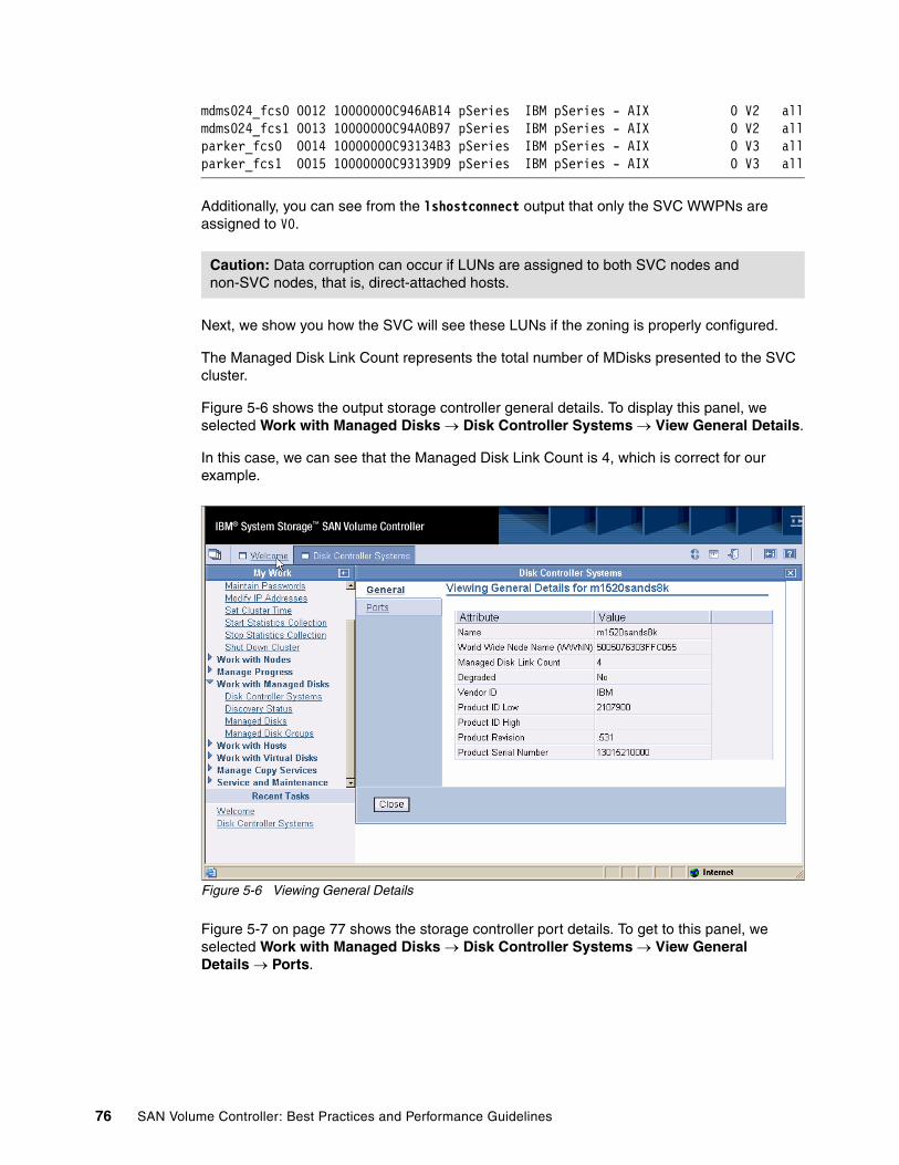
mdms024_fcs0 0012 10000000C946AB14 pSeries IBM pSeries - AIX 0 V2 allmdms024_fcs1 0013 10000000C94A0B97 pSeries IBM pSeries - AIX 0 V2 allparker_fcs0 0014 10000000C93134B3 pSeries IBM pSeries - AIX 0 V3 allparker_fcs1 0015 10000000C93139D9 pSeries IBM pSeries - AIX 0 V3 all
Additionally, you can see from the lshostconnect output that only the SVC WWPNs are assigned to V0.
Next, we show you how the SVC will see these LUNs if the zoning is properly configured.
The Managed Disk Link Count represents the total number of MDisks presented to the SVC cluster.
Figure 5-6 shows the output storage controller general details. To display this panel, we selected Work with Managed Disks → Disk Controller Systems → View General Details.
In this case, we can see that the Managed Disk Link Count is 4, which is correct for our example.
Figure 5-6 Viewing General Details
Figure 5-7 on page 77 shows the storage controller port details. To get to this panel, we selected Work with Managed Disks → Disk Controller Systems → View General Details → Ports.
Caution: Data corruption can occur if LUNs are assigned to both SVC nodes and non-SVC nodes, that is, direct-attached hosts.
76 SAN Volume Controller: Best Practices and Performance Guidelines

Figure 5-7 Viewing Port Details
Here a path represents a connection from a single node to a single LUN. Because we have four nodes and four LUNs in this example configuration, we expect to see a total of 16 paths with all paths evenly distributed across the available storage ports. We have validated that this configuration is correct, because we see eight paths on one WWPN and eight paths on the other for a total of 16 paths.
5.10 WWPN to physical port translation
Storage controller WWPNs can be translated to physical ports on the controllers for isolation and debugging purposes. Additionally, you can use this information for validating redundancy across hardware boundaries.
In Example 5-8, we show the WWPN to physical port translations for the ESS.
Example 5-8 ESS
WWPN format for ESS = 5005076300XXNNNN
XX = adapter location within storage controller NNNN = unique identifier for storage controller
Bay R1-B1 R1-B1 R1-B1 R1-B1 R1-B2 R1-B2 R1-B2 R1-B2Slot H1 H2 H3 H4 H1 H2 H3 H4XX C4 C3 C2 C1 CC CB CA C9
Bay R1-B3 R1-B3 R1-B3 R1-B3 R1-B4 R1-B4 R1-B4 R1-B4Slot H1 H2 H3 H4 H1 H2 H3 H4XX C8 C7 C6 C5 D0 CF CE CD
Chapter 5. Storage controller 77
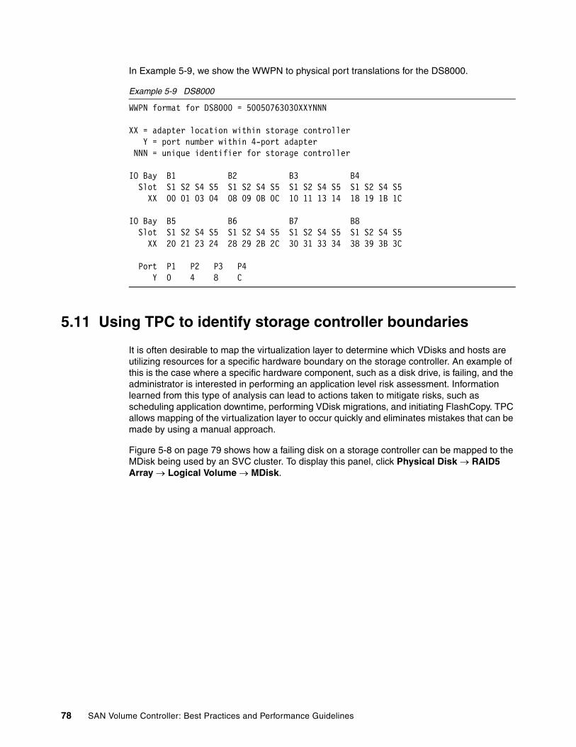
In Example 5-9, we show the WWPN to physical port translations for the DS8000.
Example 5-9 DS8000
WWPN format for DS8000 = 50050763030XXYNNN
XX = adapter location within storage controller Y = port number within 4-port adapter NNN = unique identifier for storage controller
IO Bay B1 B2 B3 B4 Slot S1 S2 S4 S5 S1 S2 S4 S5 S1 S2 S4 S5 S1 S2 S4 S5 XX 00 01 03 04 08 09 0B 0C 10 11 13 14 18 19 1B 1C
IO Bay B5 B6 B7 B8 Slot S1 S2 S4 S5 S1 S2 S4 S5 S1 S2 S4 S5 S1 S2 S4 S5 XX 20 21 23 24 28 29 2B 2C 30 31 33 34 38 39 3B 3C
Port P1 P2 P3 P4 Y 0 4 8 C
5.11 Using TPC to identify storage controller boundaries
It is often desirable to map the virtualization layer to determine which VDisks and hosts are utilizing resources for a specific hardware boundary on the storage controller. An example of this is the case where a specific hardware component, such as a disk drive, is failing, and the administrator is interested in performing an application level risk assessment. Information learned from this type of analysis can lead to actions taken to mitigate risks, such as scheduling application downtime, performing VDisk migrations, and initiating FlashCopy. TPC allows mapping of the virtualization layer to occur quickly and eliminates mistakes that can be made by using a manual approach.
Figure 5-8 on page 79 shows how a failing disk on a storage controller can be mapped to the MDisk being used by an SVC cluster. To display this panel, click Physical Disk → RAID5 Array → Logical Volume → MDisk.
78 SAN Volume Controller: Best Practices and Performance Guidelines

Figure 5-8 Mapping MDisk
Figure 5-9 completes the end-to-end view by mapping the MDisk through the SVC to the attached host. Click MDisk → MDGroup → VDisk → host disk.
Figure 5-9 Host mapping
5.12 Using TPC to measure storage controller performance
In this section, we provide a brief introduction to performance monitoring for the SVC back-end disk. When talking about storage controller performance, the back-end I/O rate refers to the rate of I/O between the storage controller cache and the storage arrays. In an SVC environment, back-end I/O is also used to refer to the rate of I/O between the SVC
Chapter 5. Storage controller 79
nodes and the controllers. Both rates are considered when monitoring storage controller performance.
The two most important metrics when measuring I/O subsystem performance are response time in milliseconds and throughput in I/Os per second (IOPS):
� Response time is measured from where commands originate and in non-SVC environments. With the SVC, we not only have to consider response time from the host to the SVC nodes, but also from the SVC nodes to the storage controllers.
� Throughput, however, can be measured at a variety of points along the data path, and the SVC adds additional points where throughput is of interest and measurements can be obtained.
TPC offers many disk performance reporting options that support the SVC environment well and also the storage controller back end for a variety of storage controller types. This is a list of the most relevant storage components where performance metrics can be collected when monitoring storage controller performance:
� Subsystem� Controller� Array� MDisk� MDG� Port
5.12.1 Approximations
These are some of the approximations that we have made or assumed:
� Throughput for storage volumes can range from 1 IOPS to more than 1,000 IOPS based mostly on the nature of the application. When the I/O rates for an MDdisk approach 1,000 IOPS, it is because that MDisk is encountering very good controller cache behavior, otherwise, such high I/O rates are not possible.
� A 10 millisecond response time is generally considered to be getting high; however, it might be perfectly acceptable depending on application behavior and requirements. For example, many On-Line Transaction Processing (OLTP) environments require response times in the 5 to 8 millisecond range, while batch applications with large sequential transfers are operating nominally in the 15 to 30 millisecond range.
� Nominal service times for disks today are 5-7 milliseconds; however, when a disk is at 50% utilization, ordinary queuing adds a wait time roughly equal to the service time, so a 10-14 millisecond response time is a reasonable goal in most environments.
� High controller cache hit ratios allow the back-end arrays to run at a higher utilization. A 70% array utilization produces high array response times; however, when averaged with cache hits, they will produce acceptable average response times.
� High SVC read hit ratios can have the same effect on array utilization in that it will allow higher MDisk utilizations and, therefore, higher array response times.
� Poor cache hit ratios require good back-end response times.
� Front-end response times typically need to be in the 5-15 millisecond range.
Note: In SVC environments, the SVC nodes interact with the storage controllers in the same way as a host. Therefore, the performance rules and guidelines that we discuss in this section are also applicable to non-SVC environments. References to MDisks are analogous with host-attached LUNs in a non-SVC environment.
80 SAN Volume Controller: Best Practices and Performance Guidelines

� Back-end response times to arrays can usually operate in the 20-25 millisecond range up to 60 milliseconds unless the cache hit ratio is low.
5.12.2 Establish a performance baseline
I/O rate often grows over time, and as I/O rates increase, response times will also increase. It is important to establish a good performance baseline so that the growth effects of the I/O workload can be monitored and trends identified that can be used to predict when additional storage performance and capacity will be required.
5.12.3 Performance metric guidelines
These are some performance metric guidelines:
� Small block reads (4k to 8K) must have average response times in the 2-15 millisecond range.
� Small block writes must have response times near 1 millisecond, because these are all cache hits. High response times with small block writes often indicate nonvolatile storage (NVS) full conditions.
� With large block reads and writes (32 KB or greater), response times are insignificant as long as throughput objectives are met.
� Read hit percentage can vary from 0% to near 100%. Anything lower than 50% is considered low; however, many database applications can run under 30%. Cache hit ratios are mostly dependent on application design. Larger cache always helps and allows back-end arrays to be driven at a higher utilization.
� Storage controller back-end read response times need to seldom exceed 25 milliseconds unless the cache read hit ratio is near 99%.
� Storage controller back-end write response times can be high due to the RAID5 and RAID10 write penalty; however, they must not exceed 60 milliseconds.
� Array throughput above 700-800 IOPS can start impacting front-end performance.
� Port response times must be less than 2 milliseconds for most I/O; however, they can reach as high as 5 milliseconds with large transfer sizes.
Figure 5-10 on page 82 is a TPC graph showing aggregate throughput for an ESS storage subsystem.
Best Practices that we recommend:
� The best general rule metrics for any system are derived from current and historical data taken from specific configurations and workloads that are meeting application and user requirements.
� Collect new sets of metrics after configuration changes are made to the storage controller configuration of the MDG configuration, such as adding or removing MDisks.
� Keep a historical record of performance metrics.
Chapter 5. Storage controller 81

Figure 5-10 Throughput
5.12.4 Storage controller back end
The back-end I/O rate is the rate of I/O between storage subsystem cache and the storage arrays. Write activity to back-end disk is from cache and is normally an asynchronous operation to move data from cache to free space in NVS.
One of the more common conditions that can impact overall performance is array overdriving. TPC allows metrics to be collected and graphed for individual arrays. Figure 5-11 on page 83 is a TPC graph showing response times for an individual ESS array.
82 SAN Volume Controller: Best Practices and Performance Guidelines
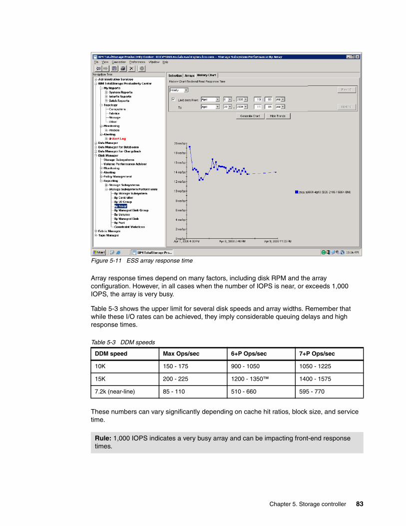
Figure 5-11 ESS array response time
Array response times depend on many factors, including disk RPM and the array configuration. However, in all cases when the number of IOPS is near, or exceeds 1,000 IOPS, the array is very busy.
Table 5-3 shows the upper limit for several disk speeds and array widths. Remember that while these I/O rates can be achieved, they imply considerable queuing delays and high response times.
Table 5-3 DDM speeds
These numbers can vary significantly depending on cache hit ratios, block size, and service time.
DDM speed Max Ops/sec 6+P Ops/sec 7+P Ops/sec
10K 150 - 175 900 - 1050 1050 - 1225
15K 200 - 225 1200 - 1350™ 1400 - 1575
7.2k (near-line) 85 - 110 510 - 660 595 - 770
Rule: 1,000 IOPS indicates a very busy array and can be impacting front-end response times.
Chapter 5. Storage controller 83

84 SAN Volume Controller: Best Practices and Performance Guidelines

Chapter 6. MDisks
In this chapter, we discuss various MDisk attributes, as well as provide an overview to the process of adding and removing MDisks from existing Managed Disk Groups (MDGs).
In this chapter, you will find the following sections:
� Back-end queue depth
� MDisk transfer size
� Selecting logical unit number (LUN) attributes for MDisks
� Tiered storage
� Adding MDisks to existing MDGs
� Remapping managed MDisks
� Controlling extent allocation order for VDisk creation
6
© Copyright IBM Corp. 2008. All rights reserved. 85
6.1 Back-end queue depth
The SAN Volume Controller (SVC) submits I/O to the back-end (MDisk) storage in the same fashion as any direct-attached host. For direct-attached storage, the queue depth is tunable at the host and is often optimized based on specific storage type as well as various other parameters, such as the number of initiators. For the SVC, the queue depth is also tuned; however, the optimal value used is calculated internally.
This is the formula SVC uses for calculating queue depth. There are two parts to the algorithm: a per MDisk limit and a per controller port limit.
Q = ((P x C) / N) / M
If Q > 60, then Q=60 (maximum queue depth is 60)
Where:
Q = The queue for any MDisk in a specific controller
P = Number of WWPNs visible to SVC in a specific controller
N = Number of nodes in the cluster
M = Number of MDisks provided by the specific controller
C = A constant. C varies by controller type:
– FAStT200, 500, DS4100, and EMC Clarion = 200
– DS4700, DS4800, DS6K, and DS8K = 1000
– Any other controller = 500
When SVC has submitted and has Q I/Os outstanding for a single MDisk (that is, it is waiting for Q I/Os to complete), it will not submit any more I/O until some I/O completes. That is, any new I/O requests for that MDisk will be queued inside the SVC. This is not desirable and indicates that back-end storage is overloaded.
The following example shows how a 4-node SVC cluster calculates queue depth for 150 LUNs on a DS8000 storage controller using six target ports:
Q = ((6 ports *1000/port)/4 nodes)/150 MDisks) = 10
With the configuration, each MDisk has a queue depth of 10.
6.2 MDisk transfer size
In the following topics, we describe the MDisk transfer size.
6.2.1 Host I/O
The maximum transfer size under normal I/O is 32 KB, because the internal cache track size is 32 KB and, therefore, destages from cache can be up to the cache track size. Although a track can hold up to 32 KB, a read or write operation can only partially populate the track; therefore, a read or write operation to the MDdisks can be anywhere from 512 bytes to 32 KB.
86 SAN Volume Controller: Best Practices and Performance Guidelines
6.2.2 FlashCopy I/O
The transfer size for FlashCopy is always 256 KB, because the grain size of flashcopy is 256 KB and any size write that changes data within a 256 KB grain will result in a single 256 KB write.
6.2.3 Coalescing writes
The SVC will coalesce writes up to the 32 KB track size if writes reside in the same tracks prior to destage. For example, if 4 KB is written into a track, then another 4 KB is written to another location in the same track, this track will move to the top of the least recently used (LRU) list in the cache upon the second write, and the track will now contain 8 KB of actual data. This can continue until the track reaches the bottom of the LRU list and is then destaged. Any contiguous data within the track will be coalesced for the destage.
Sequential writesThe SVC does not employ a caching algorithm for “explicit sequential detect”, which means coalescing of writes in SVC cache has a random component to it. For example, 4 KB writes to VDisks will translate to a mix of 4 KB, 8 KB, 16 KB, 24 KB, and 32 KB transfers to the MDisks with reducing probability as the transfer size grows.
Although larger transfer sizes tend to be more efficient, this varying transfer size has no effect on the controller’s ability to detect and coalesce sequential content to achieve “full stride writes”.
Sequential readsThe SVC uses “prefetch” logic for staging reads based on statistics maintained on 128 MB regions. If the sequential content is sufficiently high enough within a region, prefetch will occur with 32 KB reads.
6.3 Selecting LUN attributes for MDisks
The selection of LUN attributes requires the following primary considerations:
� Selecting array size� Selecting LUN size� Number of LUNs per array� Number of physical disks per array
Capacity planning considerationWhen configuring MDisks to MDGs, we advise that you consider leaving a small amount of MDisk capacity that can be used as “swing” (spare) capacity for image mode VDisk migrations. A good general rule is to allow enough space equal to the average capacity of the configured VDisks.
Selecting MDisks for MDGsAll LUNs for MDisk creation need to have the same performance characteristics. If MDisks of different performance levels are placed in the same MDG, the performance of the MDG can
Important: We generally recommend that LUNs are created to use the entire capacity of the array as described in 7.2, “Selecting number of LUNs per array” on page 102.
Chapter 6. MDisks 87
be reduced to the level of the poorest performing MDisk. Likewise, all LUNs need to also possess the same availability characteristics. Remember that the SVC does not provide any RAID capabilities. Because all MDisks are placed in the same MDG, the loss of access to any one of the MDisks within the MDG will impact the entire MDG.
We recommend these best practices for LUN selection:
� Must be the same type
� Must be the same RAID level
� Must be the same RAID width (number of physical disks in array)
� Must have the same availability and fault tolerance characteristics
MDisks created on LUNs with varying performance and availability characteristics need to be placed in separate MDGs.
RAID5 compared to RAID10In general, RAID10 arrays are capable of higher throughput for random write workloads than RAID5, because RAID10 only requires two I/Os per logical write compared to four I/Os per logical write for RAID5. For random reads and sequential workloads, there is typically no benefit. With some workloads, such as sequential writes, RAID5 often shows a performance advantage.
Obviously, selecting RAID10 for its performance advantage comes at a very high cost in usable capacity, and, in most cases, RAID5 is the best overall choice.
When considering RAID10, we recommend that you use DiskMagic to determine the difference in I/O service times between RAID5 and RAID10. If the service times are similar, the lower cost solution makes the most sense. If RAID10 shows an advantage over RAID5, the importance of that advantage must be weighed against its additional cost.
6.4 Tiered storage
The SVC makes it easy to configure multiple tiers of storage within the same SVC cluster. As we discussed in 6.3, “Selecting LUN attributes for MDisks” on page 87, it is important that MDisks that belong to the same MDG share the same availability and performance characteristics; however, grouping LUNs of like performance and availability within MDGs is an attractive feature of SVC. You can define tiers of storage using storage controllers of varying performance and availability levels. Then, you can easily provision them based on host, application, and user requirements.
When multiple storage tiers are defined, you need to take precautions to ensure storage provisioning is performed from the appropriate tiers (MDG). You can do this through MDG and MDisk naming conventions, along with clearly defined storage requirements for all hosts within the installation.
6.5 Adding MDisks to existing MDGs
In this section, we discuss adding MDisks to existing MDGs.
Note: When multiple tiers are configured, it is a best practice to clearly indicate the storage tier in the naming convention used for the MDGs and MDisks.
88 SAN Volume Controller: Best Practices and Performance Guidelines

6.5.1 Adding MDisks for capacity
Before adding MDisks to existing MDGs, ask yourself first why you are doing this? If MDisks are being added to the SVC cluster to provide additional capacity, consider adding them to a new MDG. Recognize that adding new MDisks to existing MDGs will reduce the reliability characteristics of the MDG and risk destabilizing the MDG if hardware problems exist with the new LUNs. If the MDG is already meeting its performance objectives, we recommend that, in most cases, you add the new MDisks to new MDGs rather than add the new MDisks to existing MDGs.
6.5.2 Checking access to new MDisks
You must be careful when adding MDisks to existing MDGs to ensure the availability of the MDG is not compromised by adding a faulty MDisk. Because loss of access to a single MDisk will cause the entire MDG to go offline, we recommend that Read/Write access to the MDisk is tested prior to adding the MDisk to an existing online MDG. You can test the R/W access to the MDisk by creating a test MDG, adding the new MDG, creating a test VDisk, adding it, and then performing a simple R/W to the VDisk.
6.5.3 Persistent reserve
A common condition where MDisks can be configured by SVC, but cannot perform R/W is in the case where a persistent reserve (PR) has been left on a LUN from a previously attached host. Subsystems that are exposed to this condition are ones that were previously attached with IBM Subsystem Device Driver (SDD) or SDDPCM, because support for PR comes from these multipath drivers. This condition will not be seen on DS4000 when previously attached using RDAC, because RDAC does not implement PR.
In this condition, you need to rezone LUNs and map them back to the host holding the reserve or to another host that has the capability to remove the reserve through the use of a utility, such as lquerypr (included with SDD and SDDPCM).
An alternative option is to remove the PRs from within the storage subsystem. The ESS provides an option to do this via the GUI (ESS Specialist); however for the DS6000 and DS8000, it can only be done via command line and, therefore, requires technical support.
Restriping extentsAdding MDisks to existing MDGs can result in reduced performance across the MDG due to the extent imbalance that will occur and the potential to create hot spots within the MDG. After adding MDisks to MDGs, we recommend that extents are rebalanced across all available MDisks. You accomplish this by using the command line interface (CLI) by manual command entry. Or, you can automate rebalancing the extents across all available MDisks by using a Perl script that is available from the alphaWorks® Web site:
http://www.alphaworks.ibm.com/tech/svctools
The following CLI commands can be used to identify and correct extent imbalance across MDGs:
� svcinfo lsmdiskextent � svctask migrateexts� svcinfo lsmigrate
Note: Starting at SVC 4.2.1, new function has been added so that you can test the MDisk’s ability to perform reads and writes (R/Ws) prior to attempting to add the MDisk to an MDG.
Chapter 6. MDisks 89

Renaming MDisksWe recommend that you rename MDisks from their SVC-assigned name after you discover them. Using a naming convention for MDisks that associates the MDisk to the controller and array helps during problem isolation and avoids confusion that can lead to an administration error.
Note that when multiple tiers of storage exist on the same SVC cluster, you might also want to indicate the storage tier in the name as well. For example, you can use R5 and R10 to differentiate RAID levels or you can use T1, T2, and so on to indicate defined tiers.
6.6 Removing MDisks from existing MDGs
It is critical that MDisks appear to the SVC cluster as unmanaged prior to removing their controller LUN mapping. Unmapping LUNs from the SVC that are still part of an MDG will result in the MDG going offline and impact accessing hosts.
If the MDisk has been named using the naming convention described in the previous section, the correct LUNs will be easier to identify. However, we recommend that the identification of LUNs that are being unmapped from the controller match the associated MDisk on the SVC using either the Controller LUN Number or UID fields.
Refer to 5.3, “LUN ID to MDisk translation” on page 63 for correlating ESS, DS6000, and DS8000 volume IDs to Controller Number.
Figure 6-1 on page 91 shows an example of the Controller Number and UID fields from the SVC MDisk details.
Best practice: Use a naming convention for MDisks that associates the MDisk with its corresponding controller and array within the controller, for example, DS8KR512345A22.
90 SAN Volume Controller: Best Practices and Performance Guidelines

Figure 6-1 Controller Number and UID fields from the SVC MDisk details panel
Figure 6-2 on page 92 shows an example of the Logical Drive Properties for the DS4000. Note that the DS4000 refers to UID as the Logical Drive ID.
Chapter 6. MDisks 91

Figure 6-2 Logical Drive Properties for the DS4000
6.7 Remapping managed MDisks
You generally do not unmap managed MDisks from the SVC, because it causes the MDG to go offline. However, if this has been done for some reason, it is important to know that the LUN will need to present the same UID to the SVC after it has been mapped back.
If the LUN is mapped back with a different UID, the SVC will recognize this as a new MDisk and the associated MDG will not come back online. This is a consideration for storage controllers that support LUN selection, because selecting a different LUN ID will change the UID. If the LUN has been mapped back with a different LUN ID, it will need to be remapped again using the previous LUN ID.
Another instance where the UID can change on a LUN is in the case where DS4000 support has regenerated the metadata for the logical drive definitions as part of a recovery procedure. When logical drive definitions are regenerated, the LUN will appear as a new LUN just as it does when it is created for the first time (the only exception is that the user data will still be present).
In this case, restoring the UID on a LUN back to its prior value can only be done with the assistance of DS4000 support. Both the previous UID and SSID will be required, both of
Note: The SVC identifies MDisks based on the UID of the LUN.
92 SAN Volume Controller: Best Practices and Performance Guidelines
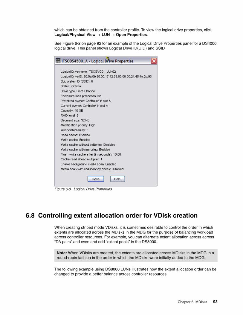
which can be obtained from the controller profile. To view the logical drive properties, click Logical/Physical View → LUN → Open Properties.
See Figure 6-2 on page 92 for an example of the Logical Drive Properties panel for a DS4000 logical drive. This panel shows Logical Drive ID(UID) and SSID.
Figure 6-3 Logical Drive Properties
6.8 Controlling extent allocation order for VDisk creation
When creating striped mode VDisks, it is sometimes desirable to control the order in which extents are allocated across the MDisks in the MDG for the purpose of balancing workload across controller resources. For example, you can alternate extent allocation across across “DA pairs” and even and odd “extent pools” in the DS8000.
The following example using DS8000 LUNs illustrates how the extent allocation order can be changed to provide a better balance across controller resources.
Note: When VDisks are created, the extents are allocated across MDisks in the MDG in a round-robin fashion in the order in which the MDisks were initially added to the MDG.
Chapter 6. MDisks 93
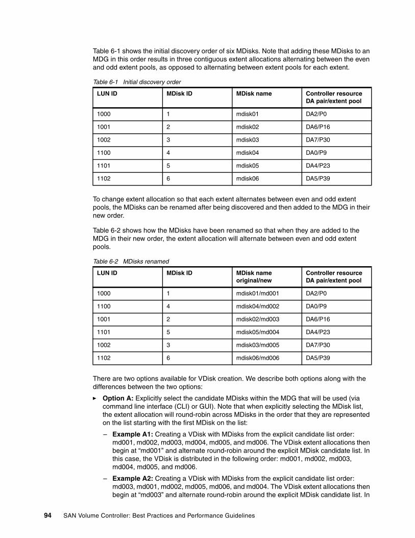
Table 6-1 shows the initial discovery order of six MDisks. Note that adding these MDisks to an MDG in this order results in three contiguous extent allocations alternating between the even and odd extent pools, as opposed to alternating between extent pools for each extent.
Table 6-1 Initial discovery order
To change extent allocation so that each extent alternates between even and odd extent pools, the MDisks can be renamed after being discovered and then added to the MDG in their new order.
Table 6-2 shows how the MDisks have been renamed so that when they are added to the MDG in their new order, the extent allocation will alternate between even and odd extent pools.
Table 6-2 MDisks renamed
There are two options available for VDisk creation. We describe both options along with the differences between the two options:
� Option A: Explicitly select the candidate MDisks within the MDG that will be used (via command line interface (CLI) or GUI). Note that when explicitly selecting the MDisk list, the extent allocation will round-robin across MDisks in the order that they are represented on the list starting with the first MDisk on the list:
– Example A1: Creating a VDisk with MDisks from the explicit candidate list order: md001, md002, md003, md004, md005, and md006. The VDisk extent allocations then begin at “md001” and alternate round-robin around the explicit MDisk candidate list. In this case, the VDisk is distributed in the following order: md001, md002, md003, md004, md005, and md006.
– Example A2: Creating a VDisk with MDisks from the explicit candidate list order: md003, md001, md002, md005, md006, and md004. The VDisk extent allocations then begin at “md003” and alternate round-robin around the explicit MDisk candidate list. In
LUN ID MDisk ID MDisk name Controller resourceDA pair/extent pool
1000 1 mdisk01 DA2/P0
1001 2 mdisk02 DA6/P16
1002 3 mdisk03 DA7/P30
1100 4 mdisk04 DA0/P9
1101 5 mdisk05 DA4/P23
1102 6 mdisk06 DA5/P39
LUN ID MDisk ID MDisk nameoriginal/new
Controller resourceDA pair/extent pool
1000 1 mdisk01/md001 DA2/P0
1100 4 mdisk04/md002 DA0/P9
1001 2 mdisk02/md003 DA6/P16
1101 5 mdisk05/md004 DA4/P23
1002 3 mdisk03/md005 DA7/P30
1102 6 mdisk06/md006 DA5/P39
94 SAN Volume Controller: Best Practices and Performance Guidelines

this case, the VDisk is distributed in the following order: md003, md001, md002, md005, md006, and md004.
� Option B: Do not explicitly select the candidate MDisks within an MDG that will be used (via command line interface (CLI) or GUI). Note that when the MDisk list is not explicitly defined, the extents will be allocated across MDisks in the order that they were added to the MDG, and the MDisk that will receive the first extent will be randomly selected:
– Example B1: Creating a VDisk with MDisks from the candidate list order (based on this definitive list from the order that the MDisks were added to the MDG: md001, md002, md003, md004, md005, and md006. The VDisk extent allocations then begin at a random MDisk starting point (let us assume “md003” is randomly selected) and alternate round-robin around the explicit MDisk candidate list based on the order that they were added to the MDG originally. In this case, the VDisk is allocated in the following order: md003, md004, md005, md006, md001, and md002.
Summary:
� Independent of the order a storage subsystem’s LUNs (volumes) are discovered by SVC, recognize that by renaming MDisks and changing the order that they are added to the MDG will influence how the VDisk’s extents are allocated.
� Renaming MDisks into a particular order and then adding them to the MDG in that order will allow the starting MDisk to be randomly selected for each VDisk created and, therefore, is the optimal method for balancing VDisk extent allocation across storage subsystem resources.
� When MDisks are added to an MDG based on the order the MDisks were discovered, the allocation order can be explicitly specified; however, the MDisk used for the first extent will always be the first MDisk specified on the list.
� When creating VDisks from the GUI:
– Recognize that you are not required to select the MDisks from the Managed Disk Candidates list and click the Add button, but rather you have the option to just input a capacity value into the “Type the size of the virtual disks” field and select whether you require formatting the VDisk. With this approach, Option B is the applied methodology for how the VDisk’s extents will be allocated within an MDG.
– When a set or subset of MDisks are selected and added (by using the Add button) to the Managed Disks Striped in this Order column, then Option A is the applied methodology for how the VDisk’s extents are explicitly distributed across the selected MDisks.
Figure 6-4 on page 96 shows the attributes panel for creating VDisks.
Chapter 6. MDisks 95

Figure 6-4 Select Attributes for a striped mode VDisk
96 SAN Volume Controller: Best Practices and Performance Guidelines

Chapter 7. Managed disk groups
This chapter contains:
� Availability considerations for planning Managed Disk Groups (MDGs)
� Selecting the number of logical unit names (LUNs) per array
� Selecting the number of arrays per MDG
� Striping compared to sequential mode
� Selecting storage controllers
7
© Copyright IBM Corp. 2008. All rights reserved. 97

7.1 Availability considerations for planning MDGs
While the SAN Volume Controller (SVC) provides many advantages through the consolidation of storage, it is important to understand the availability implications that storage subsystem failures can have on availability domains within the SVC cluster.
In this section, we point out that while the SVC offers significant performance benefits through its ability to stripe across storage arrays, it is also worthwhile considering the effects that various configurations will have on availability.
When selecting MDisks for inclusion in an MDG, performance is often the primary consideration. While performance is nearly always important, there are many instances where the availability of the configuration is traded for little or no performance gain. A performance-optimized configuration consists of putting a large number of MDisks from separate arrays (and controllers) within the same MDG. In order to accomplish this with large array sizes, this effort typically involves configuring arrays into multiple LUNs and assigning their associated MDisks to multiple MDGs. These types of configurations have an availability cost associated with them and might not yield the performance benefits that you intend.
Well designed MDGs balance the required performance and storage management objectives against availability; and therefore, all three objectives must be considered during the planning phase.
Figure 7-1 on page 99 illustrates the effect that spreading the available capacity over a greater number of MDGs has on availability. In this example, there are 40 arrays of 1 TB each for a total capacity of 40 TB. With all 40 arrays placed in the same MDG, we have put the entire 40 TB of capacity at risk in the event that one of the 40 arrays were to fail. As we spread the 40 TB out over a larger number of MDGs, we see that the failure domain for a single array failure decreases.
We see another effect when arrays are divided into multiple LUNs and the corresponding MDisks are placed in different MDGs. In this case, a single array failure impacts all MDGs in which it resides, and therefore, the failure domain expands to multiple MDGs.
Note: Configurations designed with performance in mind tend to also offer the most in terms of ease of use from a storage management perspective, because they both encourage greater numbers of resources within the same MDG.
Note: Increasing the performance “potential” of an MDG does not necessarily equate to a gain in application performance.
98 SAN Volume Controller: Best Practices and Performance Guidelines
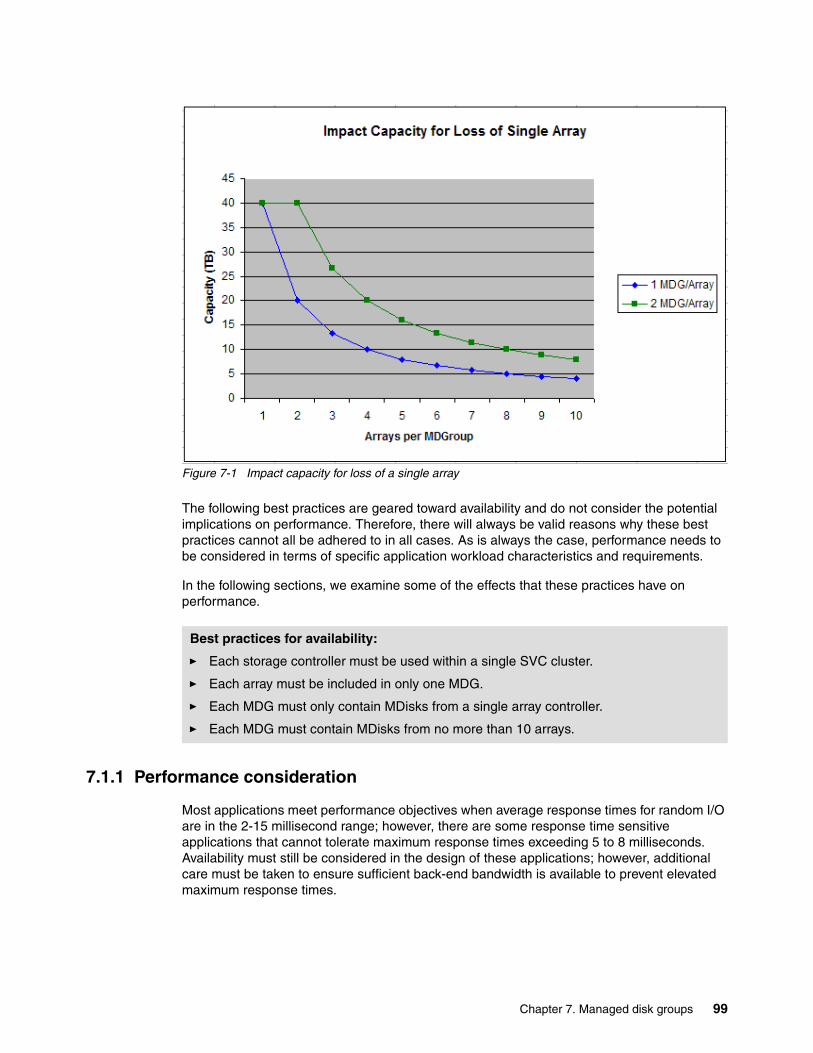
Figure 7-1 Impact capacity for loss of a single array
The following best practices are geared toward availability and do not consider the potential implications on performance. Therefore, there will always be valid reasons why these best practices cannot all be adhered to in all cases. As is always the case, performance needs to be considered in terms of specific application workload characteristics and requirements.
In the following sections, we examine some of the effects that these practices have on performance.
7.1.1 Performance consideration
Most applications meet performance objectives when average response times for random I/O are in the 2-15 millisecond range; however, there are some response time sensitive applications that cannot tolerate maximum response times exceeding 5 to 8 milliseconds. Availability must still be considered in the design of these applications; however, additional care must be taken to ensure sufficient back-end bandwidth is available to prevent elevated maximum response times.
Best practices for availability:
� Each storage controller must be used within a single SVC cluster.
� Each array must be included in only one MDG.
� Each MDG must only contain MDisks from a single array controller.
� Each MDG must contain MDisks from no more than 10 arrays.
Chapter 7. Managed disk groups 99

Considering application boundaries and dependenciesReducing hardware failure boundaries for back-end disks is only part of the things you must consider. When determining MDG layout, you also need to consider application boundaries and dependencies in order to identify any availability benefits that one configuration might have over another configuration.
Recognize that reducing hardware failure boundaries is not always advantageous from an application perspective. For instance, when an application uses multiple VDisks from an MDG, there is no advantage to splitting those VDisks between multiple MGDs, because the loss of either of the MDGs results in an application outage. However, if an SVC cluster is serving storage for multiple applications, there might be an advantage to having some applications continue uninterrupted while an application outage has occurred on other applications. It is the later scenario that places the most emphasis on availability when planning the MDG layout.
7.1.2 Selecting the MDisk Group
The SVC can be used to create tiers of storage in which each tier has different performance characteristics. You do this by only including MDisks that have the same performance characteristics within an MDG. So, if you have your storage infrastructure with, for example, three classes of storage pool, you create each VDisk in the class of storage that most closely matches its expected performance characteristics.
Because migrating between storage pools, or rather MDGs, is disruptive to the users if the actual performance is different than expected, it is an easy task to migrate the pool that has the desired performance characteristics.
We recommend putting production data on Serial Advanced Technology Attachment (SATA) disk drives only in extremely exceptional circumstances. Although SATA drives are relatively inexpensive for infrequently accessed storage, they have a high cost per I/O as shown in Figure 7-2 on page 101.
Note: We highly recommend that you use DiskMagic to size the performance demand for specific workloads. You can obtain a copy of DiskMagic, which can assist you with this effort, from:
http://www.intellimagic.net
100 SAN Volume Controller: Best Practices and Performance Guidelines

Figure 7-2 Relative costs of disk drives
Batch and OLTP workloadsClients often want to know whether to mix their batch and online transaction processing (OLTP) workloads in the same MDG. Batch and OLTP workloads might both require the same tier of storage, but in many SVC installations, there are multiple MDGs in the same storage tier so that the workloads can be separated.
We usually recommend mixing workloads so that the maximum resources are available to any workload when needed. However, batch workloads are a good example of the opposing point of view. There is a fundamental problem with letting batch and online work share resources: the amount of I/O resources that a batch job can consume is often limited only by the amount available.
To address this problem, it obviously can help to segregate the batch workload to its own MDG, but this does not necessarily prevent node or path resources from being overrun. Those resources might also need to be considered if you implement a policy of batch isolation.
For SVC, an interesting alternative is to cap the data rate at which batch volumes are allowed to run. This is done by limiting the maximum throughput of a VDisk; see 8.2.5, “Governing of VDisks” on page 122. This can potentially let online work benefit from periods when the batch load is light while limiting the damage when the batch load is heavy.
Note: It can be better to move users up the performance spectrum rather than down. People rarely complain if performance increases. So, if there is uncertainty about which pool is the correct one to use, use the pool with the lower performance and move the users up to the higher performing pool later if required.
Chapter 7. Managed disk groups 101

A lot depends on the timing of when the workloads will run. If it is mainly OLTP during the day shift and the batch workloads run at night, there is no problem with mixing the workloads in the same MDG. If the two workloads run concurrently and if the batch workload runs with no cap or throttling and requires high levels of I/O throughput, we recommend that wherever possible, the workloads are segregated onto different MDGs that are supported by different disks, raid arrays, and resources.
7.2 Selecting number of LUNs per array
We generally recommend that LUNs are configured to use the entire array. This is especially true for midrange storage controllers where multiple LUNs that are configured to an array have shown to result in a significant performance degradation. The performance degradation is attributed mainly to smaller cache sizes and the inefficient use of available cache, defeating the controller’s ability to perform “full stride writes” for RAID5 arrays. Additionally, I/O queues for multiple LUNs directed at the same array can have a tendency to overdrive the array.
Higher end storage controllers, such as the DS8000, make this much less of an issue through the use of large cache sizes. On these controllers, a slight performance advantage can be seen under certain workloads. However even on higher end storage controllers, most workloads show the difference between a single LUN per array compared to multiple LUNs per array to be negligible. One thing to remember when creating multiple LUNs per array is the manageability aspects of this type of a configuration. Care must be taken in regard to the placement of these LUNs so that you do not create conditions where overdriving an array can occur. Additionally, placing these LUNs in multiple MDGs expands failure domains considerably as we discussed in 7.1, “Availability considerations for planning MDGs” on page 98.
Table 7-1 provides our recommended guidelines for array provisioning.
Table 7-1 Array provisioning
7.2.1 Performance comparison of one compared to two LUNs per array
The following example shows a comparison between one LUN per array as opposed to two LUNs using DS8000 arrays. Because any performance benefit to be gained relies on having both LUNs within an array to be evenly loaded, this comparison was performed by placing both LUNs for each array within the same MDG. Testing was performed on two MDGs with eight MDisks per MDG. Table 7-2 on page 103 shows the MDG layout for Config1 with two LUNs per array and Table 7-3 on page 103 shows the MDG layout for Config2 with a single LUN per array.
Controller type LUNs per array
DS4000 1
DS6000 1
DS8000 1 - 2
ESS 1 - 2
102 SAN Volume Controller: Best Practices and Performance Guidelines

Table 7-2 Two LUNs per array
Table 7-3 One LUN per array
Testing was performed using a 4-node cluster with two I/O Groups and eight VDisks per MDG.
The following workloads were used in the testing:
� Ran-R/W-50/50-0%CH
� Seq-R/W-50/50-25%CH
� Seq-R/W-50/50-0%CH
� Ran-R/W-70/30-25%CH
� Ran-R/W-50/50-25%CH
� Ran-R/W-70/30-0%CH
� Seq-R/W-70/30-25%CH
� Seq-R/W-70/30-0%CH
The following performance metrics were collected for a single MDG using TotalStorage Productivity Center (TPC). Figure 7-3 on page 104 and Figure 7-4 on page 105 show the IOPS and response time comparisons between Config1 and Config2.
DS8000 array LUN1 LUN2
Array1 MDG1 MDG1
Array2 MDG1 MDG1
Array3 MDG1 MDG1
Array4 MDG1 MDG1
Array5 MDG2 MDG2
Array6 MDG2 MDG2
Array7 MDG2 MDG2
Array8 MDG2 MDG2
DS8000 array LUN1
Array1 MDG1
Array2 MDG1
Array3 MDG1
Array4 MDG1
Array5 MDG2
Array6 MDG2
Array7 MDG2
Array8 MDG2
Note: CH=Cache Hit, 25%CH means that 25% of all I/Os are read cache hits.
Chapter 7. Managed disk groups 103

Figure 7-3 IOPS comparison between two LUNs per array and one LUN per array
104 SAN Volume Controller: Best Practices and Performance Guidelines

Figure 7-4 Response time comparison between two LUNs per array and one LUN per array
The test shows a small response time advantage to the two LUNs per array configuration and a small IOPS advantage to the one LUN per array configuration for sequential workloads. Overall, the performance differences between these configurations are minimal.
7.3 Selecting the number of arrays per MDG
The capability to stripe across disk arrays is the single most important performance advantage of the SVC; however, the more arrays you stripe across is not necessarily better. The objective here is to only add as many arrays to a single MDG as required to meet the performance objectives. Because it is usually difficult to determine what is required in terms of performance, the tendency is to add far too many arrays to a single MDG, which again increases the failure domain as we discussed previously.
It is also worthwhile to consider the effect of aggregate load across multiple MDGs. It is clear that striping workload across multiple arrays has a positive effect on performance when you are talking about dedicated resources, but the performance gains diminish as the aggregate load increases across all available arrays. For example, if you have a total of eight arrays and are striping across all eight arrays, your performance is much better than if you were striping across only four arrays. However, if the eight arrays are divided into two LUNs each and are also included in another MDG, the performance advantage drops as the load of MDG2 approaches that of MDG1. This means that when workload is spread evenly across all MDGs, there will be no difference in performance.
More arrays in the MDG have more of an effect with lower performing storage controllers. So, for example, we require fewer arrays from a DS8000 than we do from a DS4000 to achieve the same performance objectives. Table 7-4 on page 106 shows the recommended number of
Chapter 7. Managed disk groups 105

arrays per MDG that is appropriate for general cases. Again, when it comes to performance, there can always be exceptions.
DA Pair considerations for selecting ESS and DS8000 arraysThe ESS and DS8000 storage architectures both access disks through pairs of device adapters (DA Pairs) with one adapter in each controller. The ESS contains four DA Pairs and the DS8000 scales from two to eight DA Pairs. When possible, consider adding arrays to MDGs based on multiples of the installed DA Pairs. For example, if the storage controller contains six DA Pairs, use either six or 12 arrays in the MDG with each array being on a different DA Pair.
Table 7-4 Recommended number of arrays per MDG
Performance comparison of reducing the number of arrays per MDGThe following test compares the performance between eight arrays per MDG and four arrays per MDG. The configuration with eight arrays per MDG represents a performance-optimized configuration, and the four arrays per MDG represents a configuration that has better availability characteristics.
Testing was performed on the following configuration:
� There are eight ranks from a DS8000.
� Each rank is configured as one RAID5 array.
� Each RAID5 array is divided into four LUNs.
� Four MDGs are configured.
� Each MDG uses one LUN (MDisk) from each of the eight arrays.
� The VDisks are created in sequential mode.
The array to MDisk mapping for this configuration is represented in Table 7-5.
Table 7-5 Configuration one: Each array is contained in four MDGs
You can see from this design that if a single array fails, all four MDGs are affected, and all VDisks that are using storage from this DS8000 fail.
Controller type Arrays per MDG
DS4000 4 - 24
ESS/DS8000 4 - 12
DS8000 array LUN1 LUN2 LUN3 LUN4
Array1 MDG1 MDG2 MDG3 MDG4
Array2 MDG1 MDG2 MDG3 MDG4
Array3 MDG1 MDG2 MDG3 MDG4
Array4 MDG1 MDG2 MDG3 MDG4
Array5 MDG1 MDG2 MDG3 MDG4
Array6 MDG1 MDG2 MDG3 MDG4
Array7 MDG1 MDG2 MDG3 MDG4
Array8 MDG1 MDG2 MDG3 MDG4
106 SAN Volume Controller: Best Practices and Performance Guidelines

An alternative to this configuration is shown in Table 7-6. Here, the arrays are divided into two LUNs each, and there are half the number of arrays for each MDG as there were in the first configuration. In this design, the failure boundary of an array failure is cut in half, because any single array failure only affects half of the MDGs.
Table 7-6 Configuration two: Each array is contained in two MDGs
We collected the following performance metrics using TPC to compare these configurations.
The first test was performed with all four MDGs evenly loaded. Figure 7-5 on page 108 and Figure 7-6 on page 109 show the IOPS and response time comparisons between Config1 and Config2 for varying workloads.
DS8000 array LUN1 LUN2
Array1 MDG1 MDG3
Array2 MDG1 MDG3
Array3 MDG1 MDG3
Array4 MDG1 MDG3
Array5 MDG2 MDG4
Array6 MDG2 MDG4
Array7 MDG2 MDG4
Array8 MDG2 MDG4
Chapter 7. Managed disk groups 107
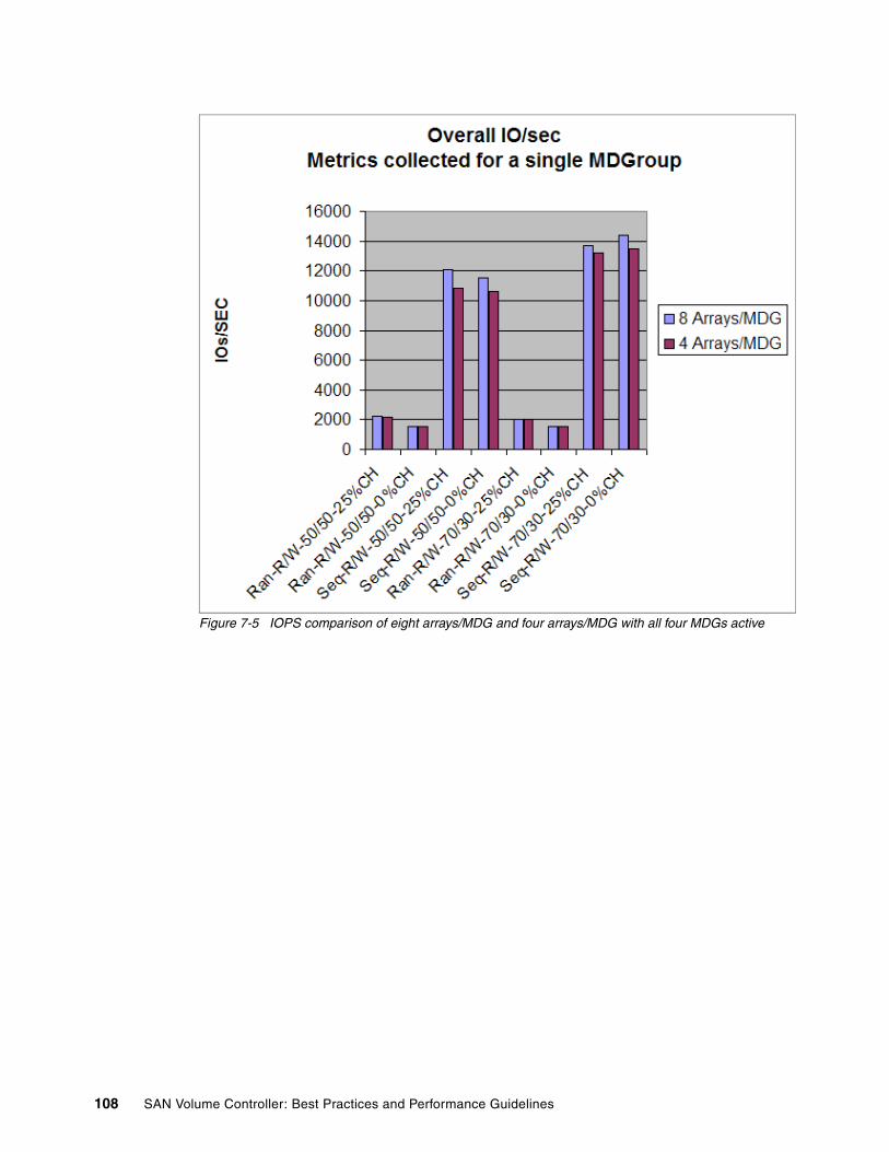
Figure 7-5 IOPS comparison of eight arrays/MDG and four arrays/MDG with all four MDGs active
108 SAN Volume Controller: Best Practices and Performance Guidelines
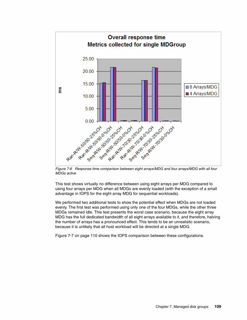
Figure 7-6 Response time comparison between eight arrays/MDG and four arrays/MDG with all four MDGs active
This test shows virtually no difference between using eight arrays per MDG compared to using four arrays per MDG when all MDGs are evenly loaded (with the exception of a small advantage in IOPS for the eight array MDG for sequential workloads).
We performed two additional tests to show the potential effect when MDGs are not loaded evenly. The first test was performed using only one of the four MDGs, while the other three MDGs remained idle. This test presents the worst case scenario, because the eight array MDG has the full dedicated bandwidth of all eight arrays available to it, and therefore, halving the number of arrays has a pronounced effect. This tends to be an unrealistic scenario, because it is unlikely that all host workload will be directed at a single MDG.
Figure 7-7 on page 110 shows the IOPS comparison between these configurations.
Chapter 7. Managed disk groups 109
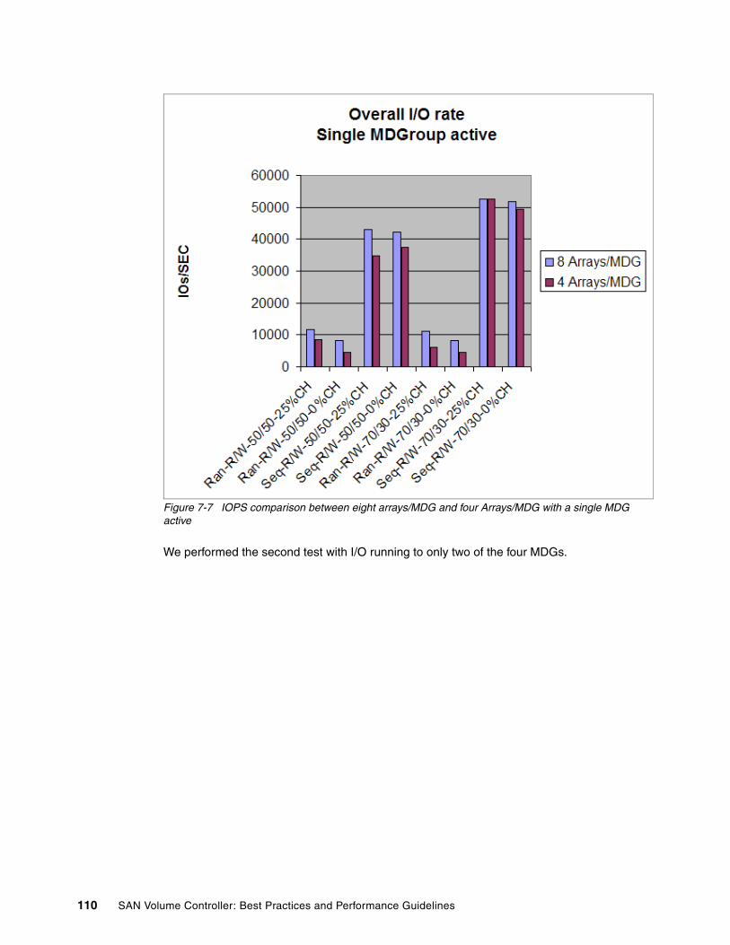
Figure 7-7 IOPS comparison between eight arrays/MDG and four Arrays/MDG with a single MDG active
We performed the second test with I/O running to only two of the four MDGs.
110 SAN Volume Controller: Best Practices and Performance Guidelines

Figure 7-8 IOPS comparison between eight arrays/MDG and four arrays/MDG with two MDGs active
Figure 7-8 shows the results from the test where only two of the four MDGs are loaded. This test shows no difference between the eight arrays per MDG configuration and the four arrays per MDG configuration for random workload. This test shows a small advantage to the eight arrays per MDG configuration for sequential workloads.
Our conclusions are:
� The performance advantage with striping across a larger number of arrays is not as pronounced as you might expect.
� You must consider the number of MDisks per array along with the number of arrays per MDG to understand aggregate MDG loading effects.
� Availability improvements can be achieved without compromising performance objectives.
7.4 Striping compared to sequential type
With very few exceptions, you must always configure VDisks using striping type.
However, one exception to this rule is an environment where you have 100% sequential workload where disk loading across all VDisks is guaranteed to be balanced by the nature of the application. For example, specialized video streaming applications are exceptions to this rule. Another exception is an environment where there is a high dependency on a large number of flash copies. In this case, FlashCopy loads the VDisks evenly and the sequential I/O, which is generated by the flash copies, has a higher throughput potential than what is
Chapter 7. Managed disk groups 111

possible with striping mode. This situation is a rare exception given the unlikely requirement to optimize for FlashCopy as opposed to online workload.
7.5 Selecting storage controllers
When selecting storage controller types, the decision generally comes down to the ability of the storage subsystem to meet the availability objectives of the applications. Because the SVC does not provide any data redundancy, the availability characteristics of the storage controllers have the most impact on the overall availability of the data virtualized by the SVC.
Performance becomes less of a determining factor due to the SVC’s ability to use various storage controllers regardless of whether they scale up or scale out. For example, the DS8000 is a scale-up architecture that delivers ‘best of breed’ performance per unit, and the DS4000 can be scaled out with enough units to deliver the same or better levels of performance. Because the SVC hides the scaling characteristics of the storage controllers, the inherent performance characteristics of the storage controllers tends not to be a direct determining factor.
A significant consideration when comparing native performance characteristics between subsystem types is the amount of scaling that is required to meet the performance objectives. While lower performing subsystems can typically be scaled to meet performance objectives, the additional hardware that is required lowers the availability characteristics of the SVC cluster. Remember that all storage controllers possess an inherent failure rate, and therefore, the failure rate of the MDG becomes the failure rate of the storage controller times the number of units.
Of course, there might be other factors that lead you to selecting one storage controller over another storage controller, such as utilizing available resources or a requirement for additional features and functions such as the System z attach capability.
Note: Electing to use sequential mode over striping requires a detailed understanding of the data layout and workload characteristics in order to avoid negatively impacting system performance.
112 SAN Volume Controller: Best Practices and Performance Guidelines
Chapter 8. VDisks
In this chapter, we discuss Virtual Disks (VDisks). We describe creating them, managing them, and migrating them across I/O Groups.
We then discuss VDisk performance and how you can use TotalStorage Productivity Center (TPC) to analyze performance and help guide you to possible solutions.
8
© Copyright IBM Corp. 2008. All rights reserved. 113

8.1 Creating VDisks
The creation of VDisks is fully described in the IBM Redbooks publication IBM System Storage SAN Volume Controller, SG24-6423-05. The best practices that we strongly recommend are:
� Decide on your naming convention before you begin. It is much easier to assign the correct names at the time of VDisk creation than to modify them afterwards. If you do need to change the VDisk name, use the svctask chvdisk command (see Example 8-1). This command changes the name of the VDisk TEST_TEST to TEST_NEWNAME.
Example 8-1 svctask chvdisk command
IBM_2145:ITSOCL1:admin>svctask chvdisk -name TEST_NEWNAME TEST_TEST
� Balance the VDisks across the I/O Groups in the cluster to balance the load across the cluster. At the time of VDisk creation, the workload to be put on the VDisk might not be known. In this case, if you are using the GUI, accept the system default of load balancing allocation. Using the CLI, you must manually specify the I/O Group. In configurations with large numbers of attached hosts where it is not possible to zone a host to multiple I/O Groups, it might not be possible to choose to which I/O Group to attach the VDisks. The VDisk has to be created in the I/O Group to which its host belongs. For moving a VDisk across I/O Groups, see 8.1.3, “Moving a VDisk to another I/O Group” on page 117.
� By default, the preferred node, which owns a VDisk within an I/O Group, is selected on a load balancing basis. At the time of VDisk creation, the workload to be put on the VDisk might not be known. But it is important to distribute the workload evenly on the SVC nodes within an I/O Group. The preferred node cannot easily be changed. If you need to change the preferred node, see 8.1.2, “Changing the preferred node within an I/O Group” on page 116.
� The maximum number of VDisks per I/O Group is 1024.
� The maximum number of VDisks per cluster is 4096 (eight node cluster).
� The smaller the extent size that you select, the finer the granularity of the VDisk of space occupied on the underlying storage controller. A VDisk occupies an integer number of extents, but its length does not need to be an integer multiple of the extent size. The length does need to be an integer multiple of the block size. Any space left over between the last logical block in the VDisk and the end of the last extent in the VDisk is unused. A small extent size is used in order to minimize this unused space. However, note that with the decline in disk prices, capacity is cheaper than other storage considerations, such as I/O. The counter view to this is that the smaller the extent size, the smaller the total storage volume that the SVC can virtualize (see Table 8-1 on page 115). The extent size does not affect performance. For most clients, extent sizes of 128 MB or 256 MB give a reasonable balance between VDisk granularity and cluster capacity. There is no longer a default value set. Extent size is set during the Managed Disk (MDisk) Group creation.
Note: Migrating VDisks across I/O Groups is a disruptive action. Therefore, it is best to get this correct at the time of VDisk creation.
Important: VDisks can only be migrated between Managed Disk Groups (MDGs) that have the same extent size.
114 SAN Volume Controller: Best Practices and Performance Guidelines
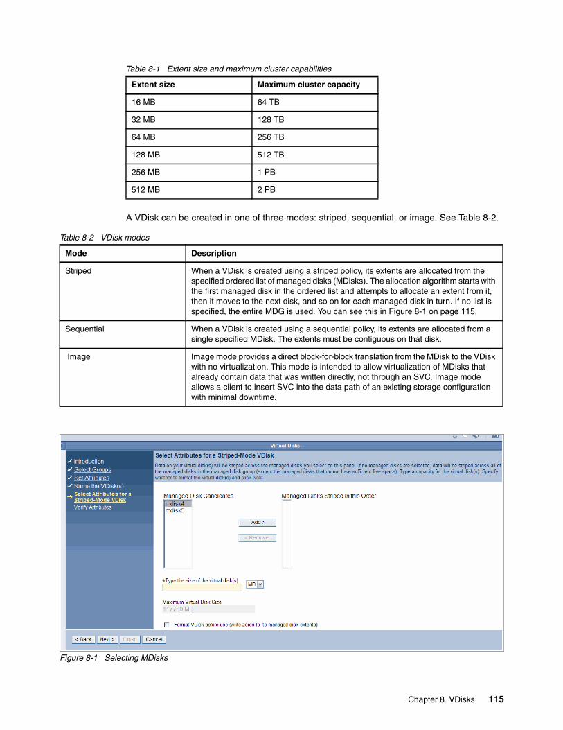
Table 8-1 Extent size and maximum cluster capabilities
A VDisk can be created in one of three modes: striped, sequential, or image. See Table 8-2.
Table 8-2 VDisk modes
Figure 8-1 Selecting MDisks
Extent size Maximum cluster capacity
16 MB 64 TB
32 MB 128 TB
64 MB 256 TB
128 MB 512 TB
256 MB 1 PB
512 MB 2 PB
Mode Description
Striped When a VDisk is created using a striped policy, its extents are allocated from the specified ordered list of managed disks (MDisks). The allocation algorithm starts with the first managed disk in the ordered list and attempts to allocate an extent from it, then it moves to the next disk, and so on for each managed disk in turn. If no list is specified, the entire MDG is used. You can see this in Figure 8-1 on page 115.
Sequential When a VDisk is created using a sequential policy, its extents are allocated from a single specified MDisk. The extents must be contiguous on that disk.
Image Image mode provides a direct block-for-block translation from the MDisk to the VDisk with no virtualization. This mode is intended to allow virtualization of MDisks that already contain data that was written directly, not through an SVC. Image mode allows a client to insert SVC into the data path of an existing storage configuration with minimal downtime.
Chapter 8. VDisks 115
With very few exceptions, you must always configure VDisks using striping mode.
8.1.1 Selecting the MDisk Group
As discussed in 7.1.2, “Selecting the MDisk Group” on page 100, you can use the SVC to create tiers (each with different performance characteristics) of storage.
8.1.2 Changing the preferred node within an I/O Group
The plan is to simplify changing the preferred node within an I/O Group in a future release of the SVC code so that a single SVC command can change the preferred node within an I/O Group. Currently, no nondisruptive or easy method exists to change the preferred node within an I/O Group.
There are three alternative techniques that you can use; they are all disruptive to the host to which the VDisk is mapped:
� Migrate the VDisk out of the SVC as an image mode-managed disk (MDisk) and then import it back as an image mode VDisk. Make sure that you select the correct preferred node. The required steps are:
a. Migrate the VDisk to an image mode VDisk.
b. Cease I/O operations to the VDisk.
c. Disconnect the VDisk from the host operating system. For example, in Windows, remove the drive letter.
d. On the SVC, unmap the VDisk from the host.
e. Delete the image mode VDisk, which removes the VDisk from the MDisk group.
f. Add the image mode MDisk back into the SVC as an image mode VDisk, selecting the preferred node that you want.
g. Resume I/O operations on the host.
h. You can now migrate the image mode VDisk to a regular VDisk.
� If remote copy services are enabled on the SVC, perform an intra-cluster Metro Mirror to a target VDisk with the preferred node that you want. At a suitable opportunity:
a. Cease I/O to the VDisk.b. Flush the host buffers. c. Stop copy services and end the copy services relationship.d. Unmap the original VDisk from the host.e. Map the target VDisk to the host.f. Resume I/O operations.
� FlashCopy the VDisk to a target VDisk in the same I/O Group with the preferred node that you want, using the auto-delete option. The steps to follow are:
a. Cease I/O to the VDisk.b. Start FlashCopy.c. When the FlashCopy completes, unmap the source VDisk from the host.d. Map the target VDisk to the host.e. Resume I/O operations.
Note: Electing to use sequential mode over striping requires a detailed understanding of the data layout and workload characteristics in order to avoid negatively impacting system performance.
116 SAN Volume Controller: Best Practices and Performance Guidelines

f. Delete the source VDisk.
There is a fourth, non-SVC method of changing the preferred node within an I/O Group if the host operating system or logical volume manager supports disk mirroring. To do this, you have to:
1. Create a VDisk, the same size as the existing one, on the desired preferred node.2. Mirror the data to this VDisk using host-based logical volume mirroring.3. Remove the original VDisk from the Logical Volume Manager (LVM).
8.1.3 Moving a VDisk to another I/O Group
This is a disruptive procedure, because access to the VDisk is lost while you perform this procedure. Migrating VDisks between I/O Groups can be a potential issue if the old definitions of the VDisks are not removed from the configuration prior to importing the VDisks back to the host.
Migrating VDisks between I/O Groups is not a dynamic configuration change. The best practice is to migrate VDisks between I/O Groups with the hosts shut down. Then, follow the procedure listed in section 10.2, “Host pathing” on page 176 for the reconfiguration of SVC VDisks to hosts. We recommend that you remove the stale configuration and reboot the host in order to reconfigure the VDisks that are mapped to a host.
Ensure that when you migrate a VDisk to a new I/O Group, you quiesce all I/O operations for the VDisk. Determine the hosts that use this VDisk. Stop or delete any FlashCopy mappings or Metro or Global Mirror relationships that use this VDisk. To check if the VDisk is part of a relationship or mapping, issue the following command where vdiskname/id is the name or ID of the VDisk:
svcinfo lsvdisk vdiskname/id (variables are italicized)
Example 8-2 lists the output of the svcinfo command.
Example 8-2 Output of svcinfo lsvdisk command
id name IO_group_id IO_group_name status mdisk_grp_id mdisk_grp_name capacity type FC_id FC_name RC_id RC_name vdisk_UID fc_map_count0 Barry-0001 0 io_grp0 online 0 mdg1 5.0GB striped 60050768018101BF280000000000001F 01 Barry-0003 0 io_grp0 online 0 mdg1 5.0GB striped 60050768018101BF2800000000000021 07 Barrz-test 0 io_grp0 online 0 mdg1 65.9GB striped 60050768018101BF2800000000000023 09 Barry-0004 0 io_grp0 online 0 mdg1 5.0GB striped 60050768018101BF2800000000000022 0
Look for the FC_id and RC_id fields. If these fields are not blank, the VDisk is part of a mapping or relationship.
Chapter 8. VDisks 117
The procedure is:
1. Cease I/O operations to the VDisk.
2. Disconnect the VDisk from the host operating system. For example, in Windows, remove the drive letter.
3. Stop any copy operations.
4. Issue the command to move the VDisk (see Example 8-3). This command does not work while there is data in the SVC cache that is to be written to the VDisk. After two minutes, the data automatically destages if no other condition forces an earlier destaging.
5. On the host, rediscover the VDisk. For example in Windows, run a rescan, then either mount the VDisk or add a drive letter. See Chapter 10, “Hosts” on page 169.
6. Resume copy operations as required.
7. Resume I/O operations on the host.
After any copy relationships stop, you can move the VDisk across I/O Groups with a single command in an SVC:
svctask chvdisk -iogrp newiogrpname/id vdiskname/id
In this command, newiogrpname/id is the name or ID of the I/O Group to which you move the VDisk and vdiskname/id is the name or ID of the VDisk.
Example 8-3 shows the command to move the VDisk named VDISK-Image from its existing I/O Group, io_grp1, to io_grp0.
Example 8-3 Moving a VDisk to another I/O Group
IBM_2145:ITSOCL1:admin>svctask chvdisk -iogrp io_grp0 VDISK-Image
Migrating VDisks between I/O Groups can be a potential issue if the old definitions of the VDisks are not removed from the configuration prior to importing the VDisks to the host. Migrating VDisks between I/O Groups is not a dynamic configuration change. It must be done with the hosts shut down. Then, follow the procedure listed in Chapter 10, “Hosts” on page 169 for the reconfiguration of SVC VDisks to hosts. We recommend that you remove the stale configuration and reboot the host to reconfigure the VDisks that are mapped to a host.
For details about how to dynamically reconfigure IBM Subsystem Device Driver (SDD) for the specific host operating system, refer to Multipath Subsystem Device Driver: User’s Guide, SC30-4131-01, where this procedure is also described in great depth.
This command will not work if there is any data in the SVC cache, which has to be flushed out first. There is a -force flag; however, this flag discards the data in the cache rather than flushing it to the VDisk. If the command fails due to outstanding I/Os, it is better to wait a couple of minutes after which the SVC will automatically flush the data to the VDisk.
Note: Do not move a VDisk to an offline I/O Group under any circumstances. You must ensure that the I/O Group is online before moving the VDisks to avoid any data loss.
Note: Using the -force flag can result in data integrity issues.
118 SAN Volume Controller: Best Practices and Performance Guidelines

8.2 VDisk migration
In this section, we discuss the best practices to follow when you perform VDisk migrations.
8.2.1 Migrating across MDGs
Migrating a VDisk from one MDG to another MDG is non-disruptive to the host application using the VDisk. Depending on the workload of the SVC, there might be a slight performance impact. For this reason, we recommend that you migrate a VDisk from one MDG to another MDG when there is a relatively low load on the SVC. The extent size of the two MDGs must be the same.
8.2.2 Image type to striped type migration
When migrating existing storage into the SVC, the existing storage is brought in as image type VDisks, which means that the VDisk is based on a single MDisk. In general, we recommend that the VDisk is migrated to a striped type VDisk, that it is striped across multiple MDisks and, therefore, multiple RAID arrays as soon as it is practical. You generally expect to see a performance improvement by migrating from image type to striped type. This process is fully described in IBM System Storage SAN Volume Controller, SG24-6423-05. The command is shown in Example 8-4.
Example 8-4 Image mode migration command
svctask migratevdisk -mdiskgrp MDG-1 -threads 3 -vdisk IOTEST
This command will migrate our VDisk, IOTEST, to MDG, MDG-1, and use three threads while doing so. Note that instead of using the VDisk name, you can use its ID number.
8.2.3 Migrating to image type VDisk
An image type VDisk is a direct “straight through” mapping to exactly one image mode MDisk. If a VDisk is migrated to another MDisk, it is represented as being in managed mode during the migration. It is only represented as an image type VDisk after it has reached the state where it is a straight through mapping.
Image type disks are used to migrate existing data into an SVC and to migrate data out of virtualization. Image type VDisks cannot be expanded.
The usual reason for migrating a VDisk to an image type VDisk is that you want to remove the data on the disk to a non-virtualized environment. This operation is also carried out to enable you to change the preferred node that is used by a VDisk. See 8.1.2, “Changing the preferred node within an I/O Group” on page 116. The procedure of migrating a VDisk to an image type VDisk is non-disruptive to host I/O.
In order to migrate a striped type VDisk to an image type VDisk, you must be able to migrate to an available unmanaged MDisk. The destination MDisk must be greater than or equal to the size of the VDisk. Regardless of the mode in which the VDisk starts, it is reported as managed mode during the migration. Both of the MDisks involved are reported as being image mode during the migration. If the migration is interrupted by a cluster recovery, the migration will resume after the recovery completes.
Chapter 8. VDisks 119
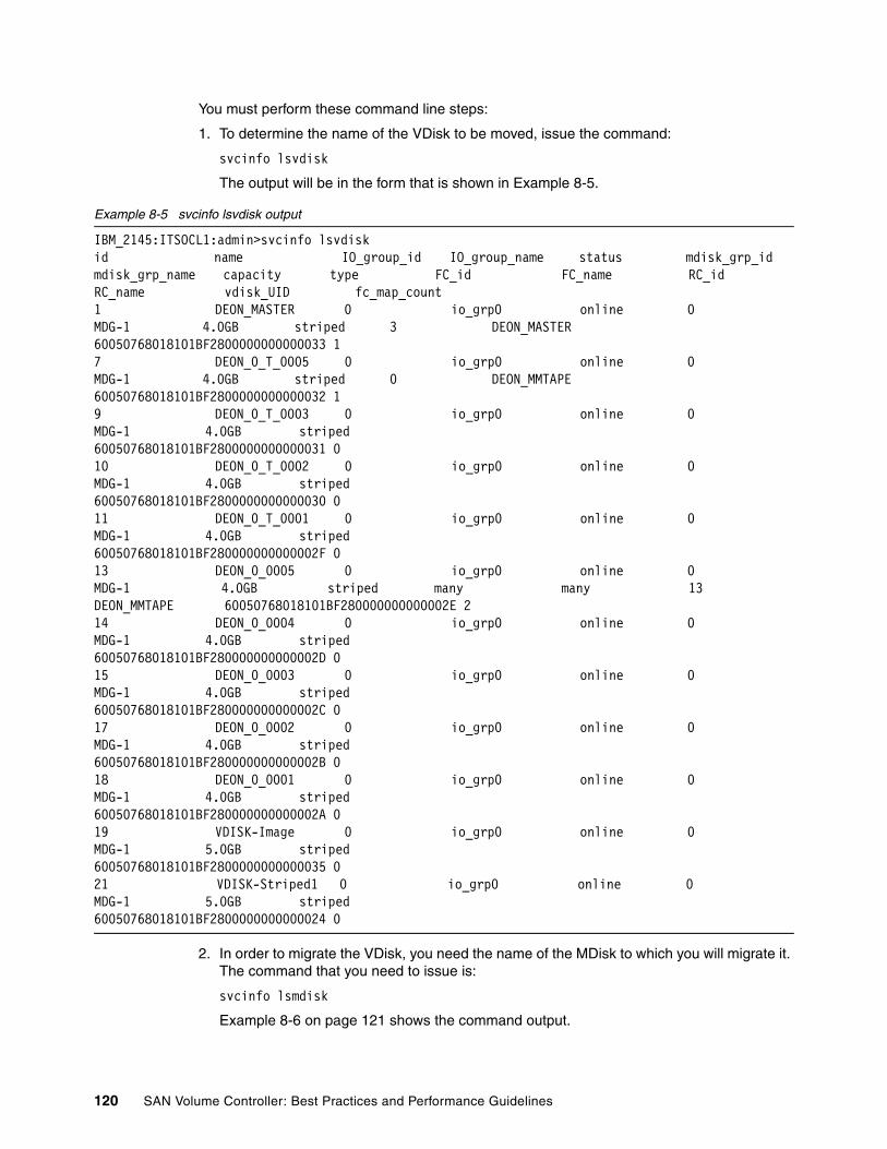
You must perform these command line steps:
1. To determine the name of the VDisk to be moved, issue the command:
svcinfo lsvdisk
The output will be in the form that is shown in Example 8-5.
Example 8-5 svcinfo lsvdisk output
IBM_2145:ITSOCL1:admin>svcinfo lsvdiskid name IO_group_id IO_group_name status mdisk_grp_id mdisk_grp_name capacity type FC_id FC_name RC_id RC_name vdisk_UID fc_map_count1 DEON_MASTER 0 io_grp0 online 0 MDG-1 4.0GB striped 3 DEON_MASTER 60050768018101BF2800000000000033 17 DEON_0_T_0005 0 io_grp0 online 0 MDG-1 4.0GB striped 0 DEON_MMTAPE 60050768018101BF2800000000000032 19 DEON_0_T_0003 0 io_grp0 online 0 MDG-1 4.0GB striped 60050768018101BF2800000000000031 010 DEON_0_T_0002 0 io_grp0 online 0 MDG-1 4.0GB striped 60050768018101BF2800000000000030 011 DEON_0_T_0001 0 io_grp0 online 0 MDG-1 4.0GB striped 60050768018101BF280000000000002F 013 DEON_0_0005 0 io_grp0 online 0 MDG-1 4.0GB striped many many 13 DEON_MMTAPE 60050768018101BF280000000000002E 214 DEON_0_0004 0 io_grp0 online 0 MDG-1 4.0GB striped 60050768018101BF280000000000002D 015 DEON_0_0003 0 io_grp0 online 0 MDG-1 4.0GB striped 60050768018101BF280000000000002C 017 DEON_0_0002 0 io_grp0 online 0 MDG-1 4.0GB striped 60050768018101BF280000000000002B 018 DEON_0_0001 0 io_grp0 online 0 MDG-1 4.0GB striped 60050768018101BF280000000000002A 019 VDISK-Image 0 io_grp0 online 0 MDG-1 5.0GB striped 60050768018101BF2800000000000035 021 VDISK-Striped1 0 io_grp0 online 0 MDG-1 5.0GB striped 60050768018101BF2800000000000024 0
2. In order to migrate the VDisk, you need the name of the MDisk to which you will migrate it. The command that you need to issue is:
svcinfo lsmdisk
Example 8-6 on page 121 shows the command output.
120 SAN Volume Controller: Best Practices and Performance Guidelines

Example 8-6 List MDisk command output
IBM_2145:ITSOCL1:admin>svcinfo lsmdiskid name status mode mdisk_grp_id mdisk_grp_name capacity ctrl_LUN_# controller_name UID0 mdisk0 online managed 0 MDG-1 600.0GB 0000000000000000 controller0 600a0b800017423300000059469cf845000000000000000000000000000000001 mdisk1 online unmanaged 5.0GB 0000000000000001 controller0 600a0b80001742330000005c46a62f2500000000000000000000000000000000
From this command, we can see that mdisk1 is a candidate for the image type migration, because it is an unmanaged MDisk.
3. We now have enough information to enter the command to migrate the VDisk to image type:
svctask migratetoimage -vdisk VDISKNAME -threads number -mdisk MDISKNAME -mdiskgrp MDISK Group Name
You can see this command in Example 8-7.
Example 8-7 migratetoimage command
IBM_2145:ITSOCL1:admin>svctask migratetoimage -vdisk VDISK-Image -threads 3 -mdisk mdisk1 -mdiskgrp MDG-1
4. If there is no unmanaged MDisk to which to migrate, you can remove an MDisk from an MDisk Group. However, you can only remove an MDisk from an MDisk Group if there are enough free extents on the remaining MDisks in the group to migrate any used extents on the MDisk that you are removing. Example 8-8 shows this command.
Example 8-8 rmdisk command
IBM_2145:ITSOCL1:admin>svctask rmmdisk -mdisk mdisk1 -force MDG-1
The -force flag is the option that automatically migrates used extents on mdisk1 to the free extents in the MDG.
8.2.4 Preferred paths to a VDisk
For I/O purposes, SAN Volume Controller nodes within the cluster are grouped into pairs, which are called I/O Groups. A single pair is responsible for serving I/O on a specific VDisk. One node within the I/O Group represents the preferred path for I/O to a specific VDisk. The other node represents the non-preferred path. This preference alternates between nodes as each VDisk is created within an I/O Group to balance the workload evenly between the two nodes.
The SVC implements the concept of each VDisk having a preferred owner node, which improves cache efficiency and cache usage. The cache component read/write algorithms are dependent on one node owning all the blocks for a specific track. The preferred node is set at the time of VDisk creation either manually by the user or automatically by the SVC. Because read miss performance is better when the host issues a read request to the owning node, you want the host to know which node owns a track. The SCSI command set provides a mechanism for determining a preferred path to a specific VDisk. Because a track is just part of a VDisk, the cache component distributes ownership by VDisk. The preferred paths are
Chapter 8. VDisks 121

then all the paths through the owning node. Therefore, a preferred path is any port on a preferred controller, assuming that SAN zoning is correct.
By default, the SVC assigns ownership of even-numbered VDisks to one node of a caching pair and the ownership of odd-numbered VDisks to the other node. It is possible for the ownership distribution in a caching pair to become unbalanced if VDisk sizes are significantly different between the nodes, or the VDisk numbers assigned to the caching pair are predominantly even or odd.
To provide some flexibility in making plans to avoid this problem, the ownership for a specific VDisk can be explicitly assigned to a specific node when the VDisk is created. A node that is explicitly assigned as an owner of a VDisk is known as the preferred node. Because it is expected that hosts will access VDisks through the preferred nodes, those nodes can become overloaded. When a node becomes overloaded, VDisks can be moved to other I/O Groups, because the ownership of a VDisk cannot be changed after the VDisk is created. We described this situation in 8.1.3, “Moving a VDisk to another I/O Group” on page 117.
SDD is aware of the preferred paths that SVC sets per VDisk. SDD uses a load balancing and optimizing algorithm when failing over paths; that is, it tries the next known preferred path. If this effort fails and all preferred paths have been tried, it load balances on the non-preferred paths until it finds an available path. If all paths are unavailable, the VDisk goes offline. It can take some time, therefore, to perform path failover when multiple paths go offline.
SDD also performs load balancing across the preferred paths where appropriate.
8.2.5 Governing of VDisks
I/O governing effectively throttles the amount of IOPS (or MBs per second) that can be achieved to and from a specific VDisk. You might want to use I/O governing if you have a VDisk that has an access pattern that adversely affects the performance of other VDisks on the same set of MDisks, for example, a VDisk that uses most of the available bandwidth.
Of course, if this application is highly important, then migrating the VDisk to another set of MDisks might be advisable. However, in some cases, it is an issue with the I/O profile of the application rather than a measure of its use or importance.
Base the choice between I/O and MB as the I/O governing throttle on the disk access profile of the application. Database applications generally issue large amounts of I/O but only transfer a relatively small amount of data. In this case, setting an I/O governing throttle based on MBs per second does not achieve much. It is better to use an IOPS throttle.
At the other extreme, a streaming video application generally issues a small amount of I/O, but transfers large amounts of data. In contrast to the database example, setting an I/O governing throttle based on IOPS does not achieve much. For a streaming video application, it is better to use an MB per second throttle.
Before running the chvdisk command, run the svcinfo lsvdisk command against the VDisk that you want to throttle in order to check its parameters as shown in Example 8-9.
Example 8-9 svcinfo lsvdisk command
login as: adminAuthenticating with public key "rsa-key-20070717"
Note: The preferred node by no means signifies absolute ownership. The data can still be accessed by the partner node in the I/O Group in the event of a failure.
122 SAN Volume Controller: Best Practices and Performance Guidelines
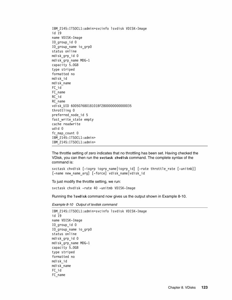
IBM_2145:ITSOCL1:admin>svcinfo lsvdisk VDISK-Imageid 19name VDISK-ImageIO_group_id 0IO_group_name io_grp0status onlinemdisk_grp_id 0mdisk_grp_name MDG-1capacity 5.0GBtype stripedformatted nomdisk_idmdisk_nameFC_idFC_nameRC_idRC_namevdisk_UID 60050768018101BF2800000000000035throttling 0preferred_node_id 5fast_write_state emptycache readwriteudid 0fc_map_count 0IBM_2145:ITSOCL1:admin>IBM_2145:ITSOCL1:admin>
The throttle setting of zero indicates that no throttling has been set. Having checked the VDisk, you can then run the svctask chvdisk command. The complete syntax of the command is:
svctask chvdisk [-iogrp iogrp_name|iogrp_id] [-rate throttle_rate [-unitmb]] [-name new_name_arg] [-force] vdisk_name|vdisk_id
To just modify the throttle setting, we run:
svctask chvdisk -rate 40 -unitmb VDISK-Image
Running the lsvdisk command now gives us the output shown in Example 8-10.
Example 8-10 Output of lsvdisk command
IBM_2145:ITSOCL1:admin>svcinfo lsvdisk VDISK-Imageid 19name VDISK-ImageIO_group_id 0IO_group_name io_grp0status onlinemdisk_grp_id 0mdisk_grp_name MDG-1capacity 5.0GBtype stripedformatted nomdisk_idmdisk_nameFC_idFC_name
Chapter 8. VDisks 123
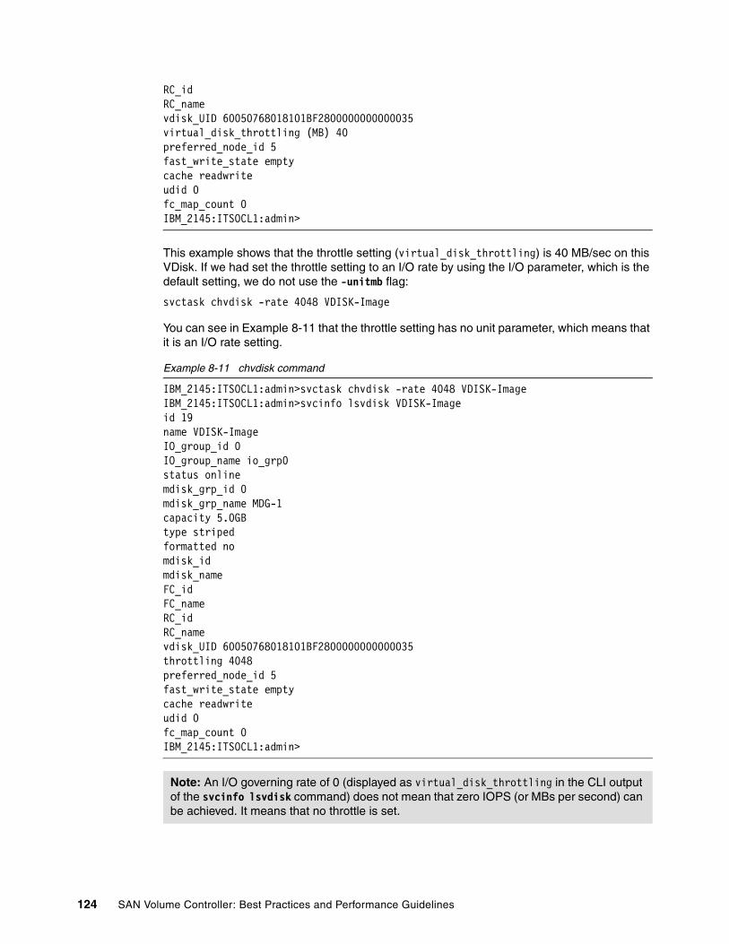
RC_idRC_namevdisk_UID 60050768018101BF2800000000000035virtual_disk_throttling (MB) 40preferred_node_id 5fast_write_state emptycache readwriteudid 0fc_map_count 0IBM_2145:ITSOCL1:admin>
This example shows that the throttle setting (virtual_disk_throttling) is 40 MB/sec on this VDisk. If we had set the throttle setting to an I/O rate by using the I/O parameter, which is the default setting, we do not use the -unitmb flag:
svctask chvdisk -rate 4048 VDISK-Image
You can see in Example 8-11 that the throttle setting has no unit parameter, which means that it is an I/O rate setting.
Example 8-11 chvdisk command
IBM_2145:ITSOCL1:admin>svctask chvdisk -rate 4048 VDISK-ImageIBM_2145:ITSOCL1:admin>svcinfo lsvdisk VDISK-Imageid 19name VDISK-ImageIO_group_id 0IO_group_name io_grp0status onlinemdisk_grp_id 0mdisk_grp_name MDG-1capacity 5.0GBtype stripedformatted nomdisk_idmdisk_nameFC_idFC_nameRC_idRC_namevdisk_UID 60050768018101BF2800000000000035throttling 4048preferred_node_id 5fast_write_state emptycache readwriteudid 0fc_map_count 0IBM_2145:ITSOCL1:admin>
Note: An I/O governing rate of 0 (displayed as virtual_disk_throttling in the CLI output of the svcinfo lsvdisk command) does not mean that zero IOPS (or MBs per second) can be achieved. It means that no throttle is set.
124 SAN Volume Controller: Best Practices and Performance Guidelines

8.3 Cache-disabled VDisks
Cache-disabled VDisks are primarily used when you are virtualizing an existing storage infrastructure and you want to retain the existing storage system copy services. You might want to use cache-disabled VDisks where there is a lot of intellectual capital in existing copy services automation scripts. We recommend that you keep the use of cache-disabled VDisks to minimum for normal workloads.
Cache-disabled VDisks can also be used to control the allocation of cache resources. By disabling the cache for some VDisks, more cache resources will be available to cache I/Os to other VDisks in the same I/O Group. This technique is particularly effective where an I/O Group is serving some VDisks that will benefit from cache and other VDisks where the benefits of caching are small or non-existent.
8.3.1 Using underlying controller remote copy with SVC cache-disabled VDisks
Where synchronous or asynchronous remote copy is used in the underlying storage controller, the controller LUNS at both the source and destination must be mapped through the SVC as image mode disks with the SVC cache disabled. Note that of course it is possible to access either the source or the target of the remote copy from a host directly, rather than through the SVC. The SVC copy services can be usefully employed with the image mode VDisk representing the primary site of the controller remote copy relationship. It does not make sense to use SVC copy services with the VDisk at the secondary site, because the SVC does not see the data flowing to this LUN through the controller.
Figure 8-2 on page 126 shows the relationships among the SVC, the VDisk, and the underlying storage controller for a cache-disabled VDisk.
Chapter 8. VDisks 125
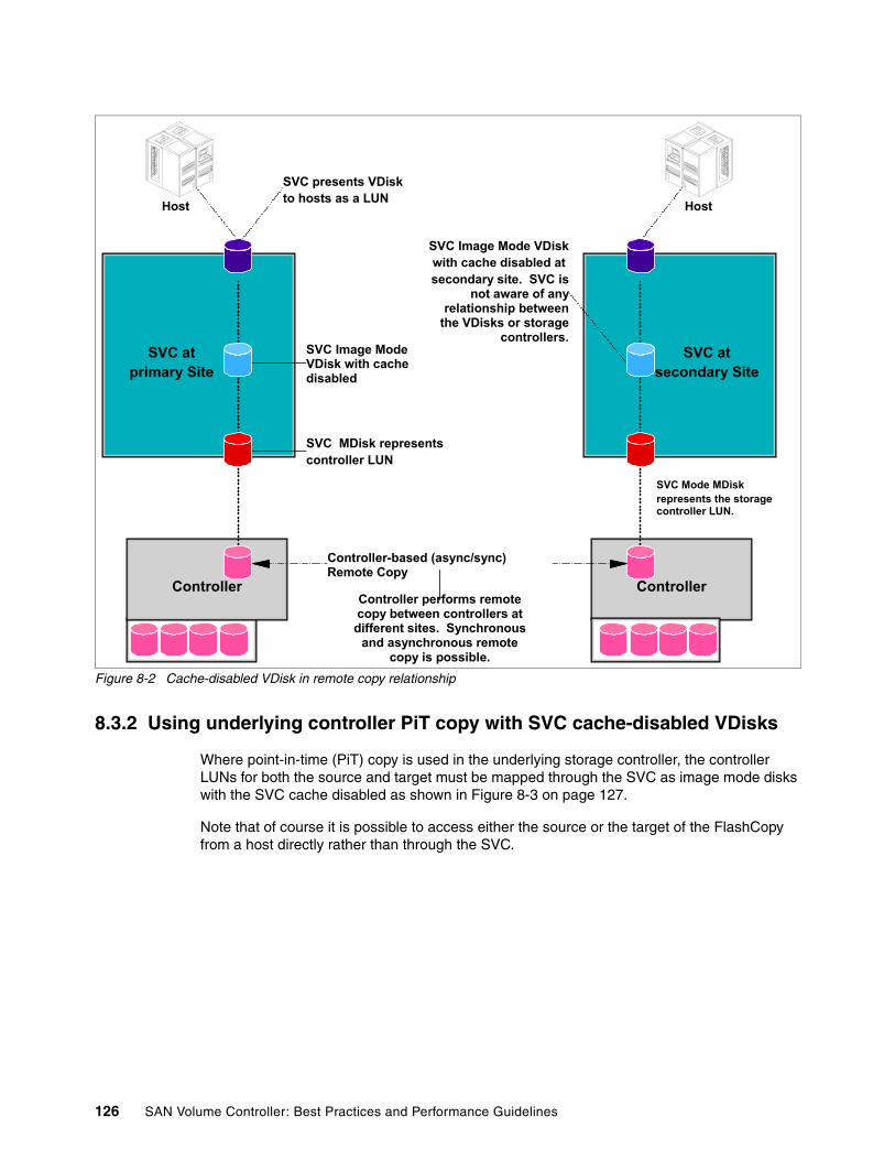
Figure 8-2 Cache-disabled VDisk in remote copy relationship
8.3.2 Using underlying controller PiT copy with SVC cache-disabled VDisks
Where point-in-time (PiT) copy is used in the underlying storage controller, the controller LUNs for both the source and target must be mapped through the SVC as image mode disks with the SVC cache disabled as shown in Figure 8-3 on page 127.
Note that of course it is possible to access either the source or the target of the FlashCopy from a host directly rather than through the SVC.
Host
Controller
SVC presents VDiskto hosts as a LUN
SVC atprimary Site
SVC Image Mode VDisk with cache disabled
SVC MDisk representscontroller LUN
Host
Controller
SVC atsecondary Site
SVC Image Mode VDiskwith cache disabled at secondary site. SVC is
not aware of any relationship between
the VDisks or storage controllers.
SVC Mode MDiskrepresents the storage controller LUN.
Controller-based (async/sync) Remote Copy
Controller performs remote copy between controllers at different sites. Synchronous
and asynchronous remote copy is possible.
126 SAN Volume Controller: Best Practices and Performance Guidelines
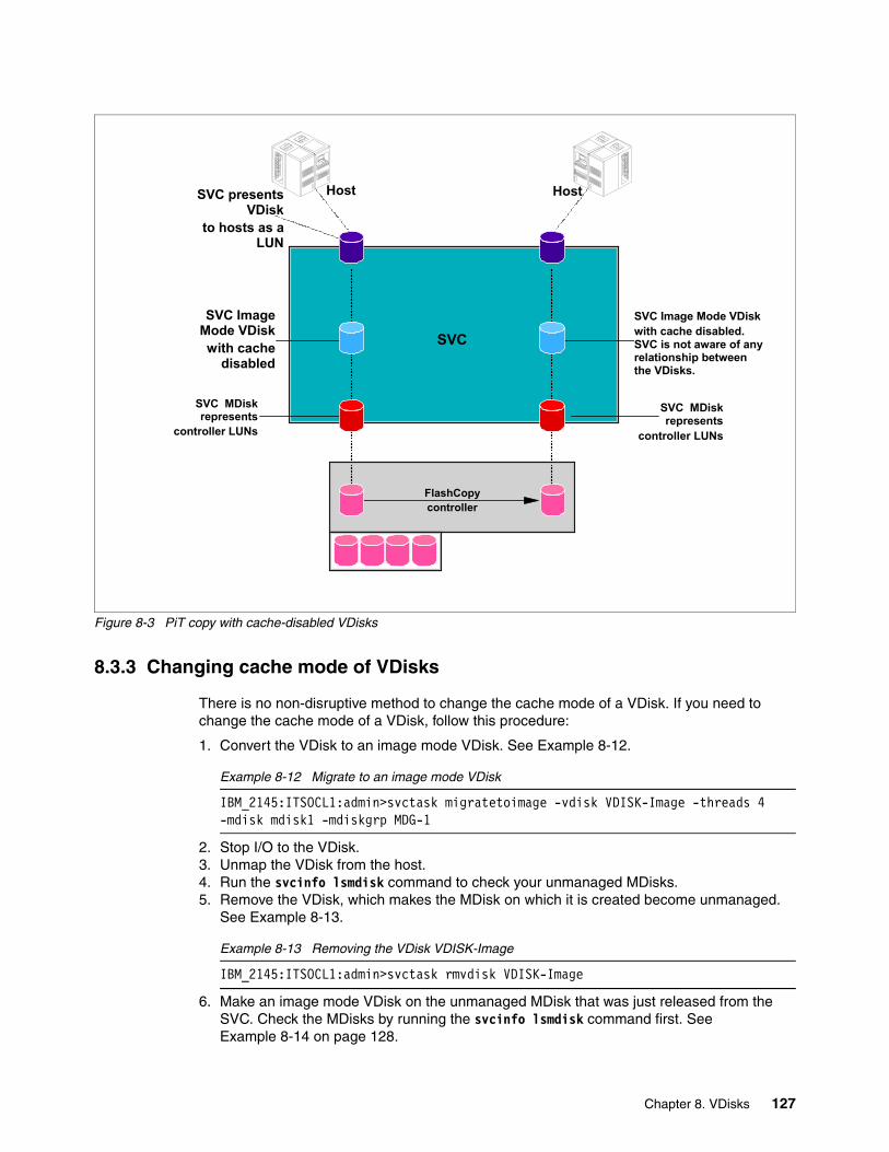
Figure 8-3 PiT copy with cache-disabled VDisks
8.3.3 Changing cache mode of VDisks
There is no non-disruptive method to change the cache mode of a VDisk. If you need to change the cache mode of a VDisk, follow this procedure:
1. Convert the VDisk to an image mode VDisk. See Example 8-12.
Example 8-12 Migrate to an image mode VDisk
IBM_2145:ITSOCL1:admin>svctask migratetoimage -vdisk VDISK-Image -threads 4 -mdisk mdisk1 -mdiskgrp MDG-1
2. Stop I/O to the VDisk.3. Unmap the VDisk from the host.4. Run the svcinfo lsmdisk command to check your unmanaged MDisks.5. Remove the VDisk, which makes the MDisk on which it is created become unmanaged.
See Example 8-13.
Example 8-13 Removing the VDisk VDISK-Image
IBM_2145:ITSOCL1:admin>svctask rmvdisk VDISK-Image
6. Make an image mode VDisk on the unmanaged MDisk that was just released from the SVC. Check the MDisks by running the svcinfo lsmdisk command first. See Example 8-14 on page 128.
Host
SVC
SVC presents VDisk
to hosts as a LUN
SVC Image Mode VDiskwith cache
disabled
SVC MDisk represents
controller LUNs
Host
FlashCopycontroller
SVC Image Mode VDiskwith cache disabled. SVC is not aware of any relationship between the VDisks.
SVC MDisk represents
controller LUNs
Chapter 8. VDisks 127

Example 8-14 Making a cache-disabled VDisk
IBM_2145:ITSOCL1:admin>svcinfo lsmdiskid name status mode mdisk_grp_id mdisk_grp_name capacity ctrl_LUN_# controller_name UID0 mdisk0 online managed 0 MDG-1 600.0GB 0000000000000000 controller0 600a0b800017423300000059469cf845000000000000000000000000000000001 mdisk1 online unmanaged 5.0GB 0000000000000001 controller0 600a0b80001742330000005c46a62f25000000000000000000000000000000002 mdisk2 online managed 0 MDG-1 70.9GB 0000000000000002 controller0 600a0b800017443100000096469cf0e800000000000000000000000000000000IBM_2145:ITSOCL1:admin>svctask mkvdisk -mdiskgrp MDG-1 -size 5 -unit gb -iogrp io_grp0 -name VDISK-Image -cache noneVirtual Disk, id [19], successfully createdIBM_2145:ITSOCL1:admin>svcinfo lsvdisk VDISK-Imageid 19name VDISK-ImageIO_group_id 0IO_group_name io_grp0status onlinemdisk_grp_id 0mdisk_grp_name MDG-1capacity 5.0GBtype stripedformatted nomdisk_idmdisk_nameFC_idFC_nameRC_idRC_namevdisk_UID 60050768018101BF2800000000000043throttling 0preferred_node_id 6fast_write_state emptycache noneudidfc_map_count 0IBM_2145:ITSOCL1:admin>
7. If you want to create the VDisk with read/write cache, you leave out the -cache parameter, because cache-enabled is the default setting. See Example 8-15.
Example 8-15 Removing VDisk and recreating with cache enabled
IBM_2145:ITSOCL1:admin>svctask rmvdisk VDISK-ImageIBM_2145:ITSOCL1:admin>svctask mkvdisk -mdiskgrp MDG-1 -size 5 -unit gb -iogrp io_grp0 -name VDISK-ImageVirtual Disk, id [19], successfully createdIBM_2145:ITSOCL1:admin>svcinfo lsvdisk VDISK-Imageid 19name VDISK-ImageIO_group_id 0
128 SAN Volume Controller: Best Practices and Performance Guidelines

IO_group_name io_grp0status onlinemdisk_grp_id 0mdisk_grp_name MDG-1capacity 5.0GBtype stripedformatted nomdisk_idmdisk_nameFC_idFC_nameRC_idRC_namevdisk_UID 60050768018101BF2800000000000044throttling 0preferred_node_id 6fast_write_state emptycache readwriteudidfc_map_count 0IBM_2145:ITSOCL1:admin>
8. You can then map the VDisk to the host and continue I/O operations after rescanning the host. See Example 8-16.
Example 8-16 Mapping VDISK-Image to host senegal
IBM_2145:ITSOCL1:admin>svctask mkvdiskhostmap -host senegal VDISK-ImageVirtual Disk to Host map, id [0], successfully createdIBM_2145:ITSOCL1:admin>
8.4 VDisk performance
The answer to many performance questions is “It depends”. This is not much use to you when trying to solve storage performance problems or rather perceived storage performance problems. But there are no absolutes with performance, so it is truly difficult to supply a simple answer for the question, “What is a good performance number for a VDisk?”.
Some people expect that the SVC will greatly add to the latency of I/O operations, because the SVC is in-band. But because the SVC is an in-band appliance, all writes are essentially write-hits, because completion is returned to the host at the point that the SVC cache has mirrored the write to its partner node. When the workload is heavy, the cache will destage write data, based on a least recently used (LRU) algorithm, thus, ensuring new host writes continue to be serviced as quickly as possible. The rate of destage is ramped up to free space more quickly when the cache reaches certain thresholds, which avoids any nasty cache full situations.
Reads are likely to be read-hits, and sequential workloads get the benefit of both controller prefetch and SVC prefetch algorithms, giving the latest SVC nodes the ability to show more than 10 GBps on large transfer sequential read miss workloads. Random reads are at the
Note: Before removing the VDisk host mapping, it is essential that you follow the procedures in Chapter 10, “Hosts” on page 169 so that you can remount the disk with its access to data preserved.
Chapter 8. VDisks 129

mercy of the storage again, and here we tie in with the “fast path” with tens of microseconds of additional latency on a read-miss. The chances are this will also be a read miss on the controller where a high-end system will respond in around 10 milliseconds. The order of magnitude of the additional latency introduced by SVC is therefore “lost in the noise”.
A VDisk, like any storage device, has three basic properties: capacity, I/O rate, and throughput as measured in megabytes per second. One of these properties will be the limiting factor in your environment. Having cache and striping across large numbers of disks can help increase these numbers. But eventually, the fundamental laws of physics apply. There will always be a limiting number. One of the major problems with designing a storage infrastructure is that while it is relatively easy to determine the required capacity, determining the required I/O rate and throughput is not so easy. All too often the exact requirement is only known after the storage infrastructure has been built, and the performance is inadequate. One of the advantages of the SVC is that it is possible to compensate for a lack of information at the design stage due to the SVC’s flexibility and the ability to non-disruptively migrate data to different types of back-end storage devices.
The throughput for VDisks can range from fairly small numbers (1 to 10 IOPS) to very large values (more than 1,000 IOPS). This throughput depends a lot on the nature of the application and across how many MDisks the VDisk is striped. When the I/O rates, or throughput, approach 1,000 IOPS per VDisk, it is either because the volume is getting very good performance, usually from very good cache behavior, or that the VDisk is striped across multiple MDisks and hence usually across multiple RAID arrays on the back-end storage system. Otherwise, it is not possible to perform so many IOPS to a VDisk that is based on a single RAID array and still have a good response time.
The MDisk I/O limit depends on many factors. The primary factor is the number of disks in the RAID array on which the MDisk is built and the speed or revolutions per minute (RPM) of the disks. But when the number of IOPS to an MDisk is near or above 1000, the MDisk is considered extremely busy. For 15K RPM disks, the limit is a bit higher. But these high I/O rates to the back-end storage systems are not consistent with good performance; they imply that the back-end RAID arrays are operating at very high utilizations, which is indicative of considerable queuing delays. Good planning demands a solution that reduces the load on such busy RAID arrays.
For more precision, we will consider the upper limit of performance for 10K and 15K RPM, enterprise class devices. Be aware that different people have different opinions about these limits, but all the numbers in Table 8-3 represent very busy disk drive modules (DDMs).
Table 8-3 DDM speeds
While disks might achieve these throughputs, these ranges imply a lot of queuing delay and high response times. These ranges probably represent acceptable performance only for batch-oriented applications, where throughput is the paramount performance metric. For online transaction processing (OLTP) applications, these throughputs might already have unacceptably high response times. Because 15K RPM DDMs are most commonly used in OLTP environments (where response time is at a premium), a simple rule is if the MDisk does more than 1000 operations per second, it is very busy, no matter what the drive’s RPM is.
DDM speed Maximum operations/second
6+P operations/second
7+P operations/second
10K 150 - 175 900 - 1050 1050 - 1225
15K 200 - 225 1200 - 1350 1400 - 1575
130 SAN Volume Controller: Best Practices and Performance Guidelines

In the absence of additional information, we often assume, and our performance models assume, that 10 milliseconds (msec) is pretty high. But for a particular application, 10 msec might be too low or too high. Many OLTP environments require response times closer to5 msec, while batch applications with large sequential transfers might run fine with 20 msec response time. The appropriate value can also change between shifts or on the weekend. A response time of 5 msec might be required from 8 am until 5 pm, while 50 msec is perfectly acceptable near midnight. It is all client and application dependent.
What really matters is the average front-end response time, which is what counts for the users. You can measure the average front-end response time by using TPC for Disk with its performance reporting capabilities. See Chapter 12, “Monitoring” on page 215 for more information.
Figure 8-4 shows the overall response time of a VDisk that is under test. Here, we have plotted the overall response time. Additionally, TPC allows us to plot read and write response times as distinct entities if one of these response times was causing problems to the user. This response time in the 1- 2 msec range gives an acceptable level of performance for OLTP applications.
Figure 8-4 VDisk overall response time
If we look at the I/O rate on this VDisk, we see the chart in Figure 8-5 on page 132, which shows us that the I/O rate to this VDisk was in the region of 2,000 IOPS. This normally is an unacceptably high response time for a LUN based on a single RAID array. However, in this case, the VDisk was striped across two MDisks, which gives us an I/O rate per MDisk in the order of 1,200 IOPS. This is high and normally gives a high user response time; however,
Chapter 8. VDisks 131

here, the SVC front-end cache mitigates the high latency at the back end, giving the user a good response time.
Although there is no immediate issue with this VDisk, if the workload characteristics change and the VDisk becomes less cache friendly, you need to consider adding another MDisk to the MDG, making sure that it comes from another RAID array, and striping the VDisk across all three MDisks.
Figure 8-5 VDisk I/O rate
8.4.1 VDisk performance
It is vital that you constantly monitor systems when they are performing well so that you can establish baseline levels of good performance. Then, if performance as experienced by the user degrades, you have the baseline numbers for a comparison. We strongly recommend that you use TPC to monitor and manage your storage environment.
OLTP workloadsProbably the most important parameter as far as VDisks are concerned is the I/O response time for OLTP workloads. After you have established what VDisk response time provides good user performance, you can set TPC alerting to notify you if this number is exceeded by about 25%. Then, you check the I/O rate of the MDisks on which this VDisk is built. If there are multiple MDisks per Raid array, you need to check the RAID array performance. All of this
132 SAN Volume Controller: Best Practices and Performance Guidelines

can be done using TPC. The “magic” number here is 1,000 IOPS, assuming that the RAID array is 6+P. See Table 8-3 on page 130.
If one of the back-end storage arrays is running at more than 1,000 IOPS and the user is experiencing poor performance because of degraded response time, this array is probably the root cause of the problem.
If users complain of response time problems, yet the VDisk response as measured by TPC has not changed significantly, this situation indicates that the problem is in the SAN network between the host and the SVC. You can diagnose where the problem is with TPC. The best way to determine the location of the problem is to use the Topology Viewer to look at the host using Datapath Explorer (DPE). This view enables you to see the paths from the host to the SVC, which we show in Figure 8-6.
Figure 8-6 DPE view of the host to the SVC
Figure 8-6 shows the paths from the disk as seen by the server through its host bus adapters (HBAs) to the SVC VDisk. By hovering the cursor over the switch port, the throughput of that port can be seen. You can also use TPC to produce reports showing the overall throughput of the ports, which we show in Figure 8-7 on page 134.
Chapter 8. VDisks 133

Figure 8-7 Throughput of the ports
TPC can present the throughput of the ports graphically over time as shown in Figure 8-8 on page 135.
134 SAN Volume Controller: Best Practices and Performance Guidelines
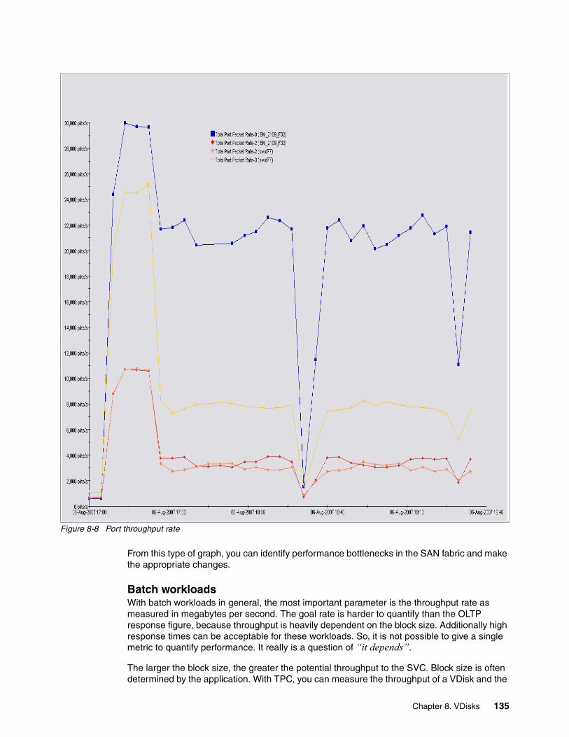
Figure 8-8 Port throughput rate
From this type of graph, you can identify performance bottlenecks in the SAN fabric and make the appropriate changes.
Batch workloadsWith batch workloads in general, the most important parameter is the throughput rate as measured in megabytes per second. The goal rate is harder to quantify than the OLTP response figure, because throughput is heavily dependent on the block size. Additionally high response times can be acceptable for these workloads. So, it is not possible to give a single metric to quantify performance. It really is a question of “it depends”.
The larger the block size, the greater the potential throughput to the SVC. Block size is often determined by the application. With TPC, you can measure the throughput of a VDisk and the
Chapter 8. VDisks 135

MDisks on which it is built. The important measure for the user is the time that the batch job takes to complete. If this time is too long, the following steps are a good starting point:
Determine the data rate that is needed for timely completion and compare it with the storage system’s capability as documented in performance white papers and Disk Magic. If the storage system is capable of greater performance:
1. Make sure that the application transfer size is as large as possible.
2. Consider increasing the number of concurrent application streams, threads, files, and partitions.
3. Make sure that the host is capable of supporting the required data rate. For example, use tests, such as DD, and use TPC to monitor the results.
4. Check whether the flow of data through the SAN is balanced by using the switch performance monitors within TPC (extremely useful).
5. Check whether all switch and host ports are operating at the maximum permitted data rate of 2 or 4 Gb per seconds.
6. Watch out for cases where the whole batch window stops on a single file or database getting read or written, which can be a practical exposure for obvious reasons. Unfortunately, sometimes there is nothing that can be done. However, it is worthwhile evaluating this situation to see whether, for example, the database can be divided into partitions, or the large file replaced by multiple smaller files. Or, the use of the SVC in combination with SDD might help with a combination of striping and added paths to multiple VDisks. These efforts can allow parallel batch streams to the VDisks and, thus, speed up bath runs.
The chart shown in Figure 8-9 on page 137 gives an indication of what can be achieved with tuning the VDisk and the application. Points A-B shows the normal steady state running of the application on the VDisk built on a single MDisk. We then migrated the VDisk so that it spanned two MDisks. Points B-C shows the drop in performance during the migration. When the migration was complete, points D-E shows that the performance had almost doubled. The application was one with 75% reads and 75% sequential access. The application was then modified so that it was 100% sequential. The resulting gain in performance is shown between points E and F.
136 SAN Volume Controller: Best Practices and Performance Guidelines
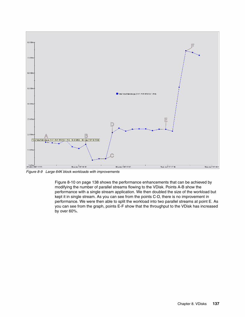
Figure 8-9 Large 64K block workloads with improvements
Figure 8-10 on page 138 shows the performance enhancements that can be achieved by modifying the number of parallel streams flowing to the VDisk. Points A-B show the performance with a single stream application. We then doubled the size of the workload but kept it in single stream. As you can see from the points C-D, there is no improvement in performance. We were then able to split the workload into two parallel streams at point E. As you can see from the graph, points E-F show that the throughput to the VDisk has increased by over 60%.
Chapter 8. VDisks 137
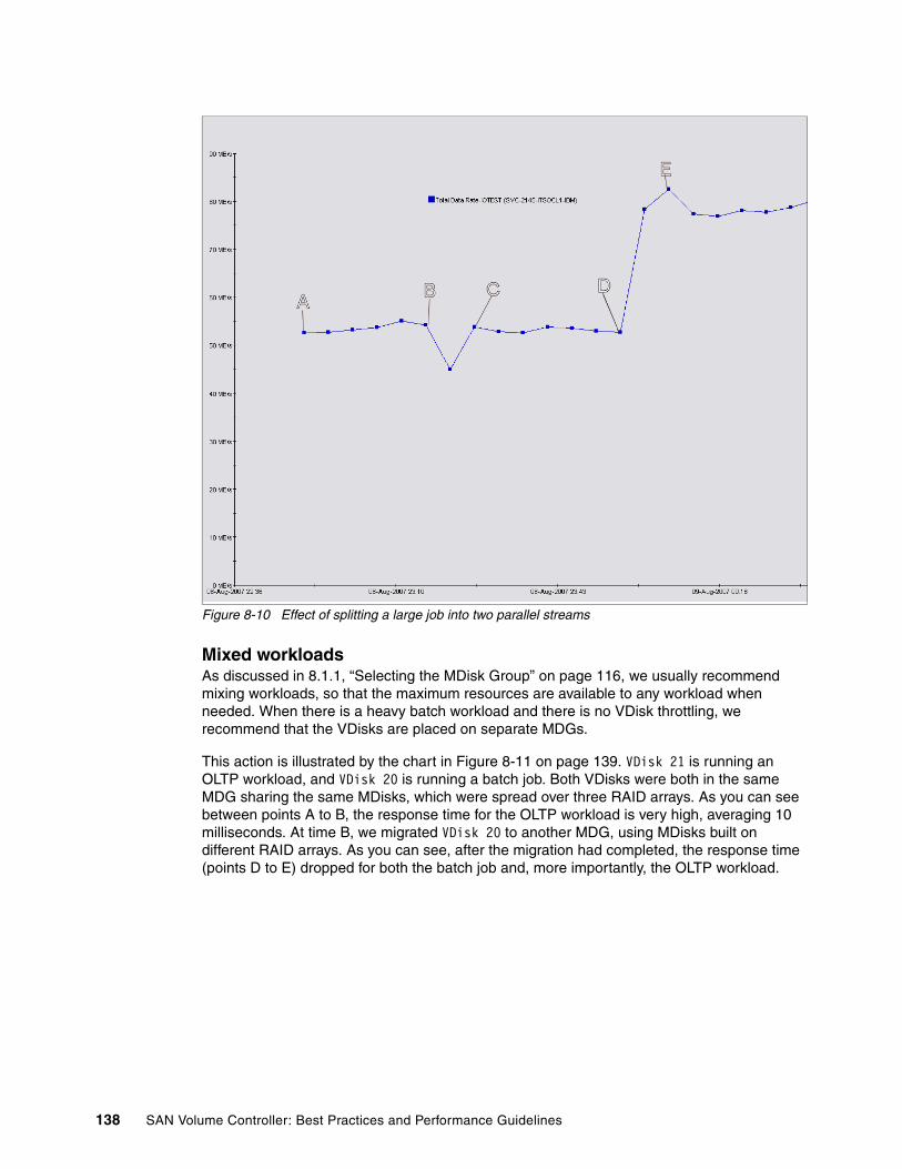
Figure 8-10 Effect of splitting a large job into two parallel streams
Mixed workloadsAs discussed in 8.1.1, “Selecting the MDisk Group” on page 116, we usually recommend mixing workloads, so that the maximum resources are available to any workload when needed. When there is a heavy batch workload and there is no VDisk throttling, we recommend that the VDisks are placed on separate MDGs.
This action is illustrated by the chart in Figure 8-11 on page 139. VDisk 21 is running an OLTP workload, and VDisk 20 is running a batch job. Both VDisks were both in the same MDG sharing the same MDisks, which were spread over three RAID arrays. As you can see between points A to B, the response time for the OLTP workload is very high, averaging 10 milliseconds. At time B, we migrated VDisk 20 to another MDG, using MDisks built on different RAID arrays. As you can see, after the migration had completed, the response time (points D to E) dropped for both the batch job and, more importantly, the OLTP workload.
138 SAN Volume Controller: Best Practices and Performance Guidelines
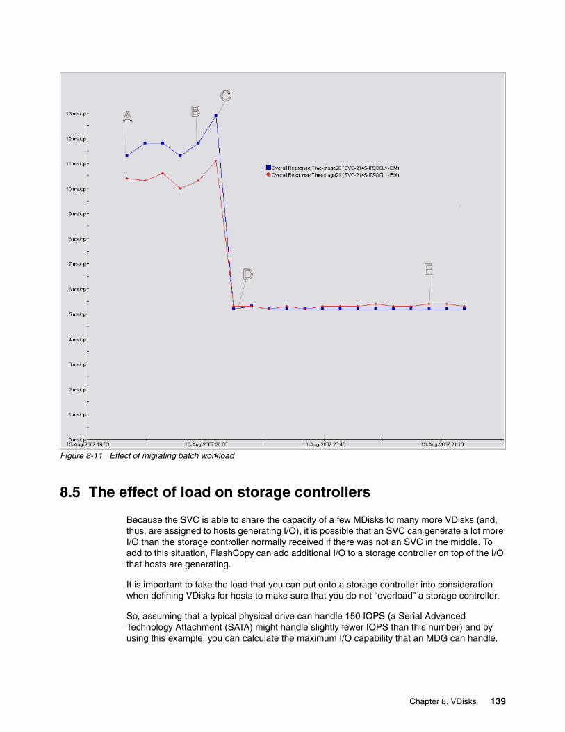
Figure 8-11 Effect of migrating batch workload
8.5 The effect of load on storage controllers
Because the SVC is able to share the capacity of a few MDisks to many more VDisks (and, thus, are assigned to hosts generating I/O), it is possible that an SVC can generate a lot more I/O than the storage controller normally received if there was not an SVC in the middle. To add to this situation, FlashCopy can add additional I/O to a storage controller on top of the I/O that hosts are generating.
It is important to take the load that you can put onto a storage controller into consideration when defining VDisks for hosts to make sure that you do not “overload” a storage controller.
So, assuming that a typical physical drive can handle 150 IOPS (a Serial Advanced Technology Attachment (SATA) might handle slightly fewer IOPS than this number) and by using this example, you can calculate the maximum I/O capability that an MDG can handle.
Chapter 8. VDisks 139

Then, as you define the VDisks and the FlashCopy mappings, calculate the maximum average I/O that the SVC will receive per VDisk before you start to overload your storage controller.
This example assumes:
� An MDisk is defined from an entire array (that is, the array only provides one LUN and that LUN is given to the SVC as an MDisk).
� Each MDisk assigned to an MDG is the same size and same RAID type and comes from a storage controller of the same type.
� MDisks from a storage controller are contained entirely in the same MDG.
The raw I/O capability of the MDG is the sum of the capabilities of its MDisks. For example, for five RAID 5 MDisks with eight component disks on a typical back-end device, the I/O capability is:
5 x ( 150 x 7 ) = 5250
This raw number might be constrained by the I/O processing capability of the back-end storage controller itself.
FlashCopy copying contributes to the I/O load of a storage controller, and thus, it must be taken into consideration. The effect of a FlashCopy is effectively adding a number of loaded VDisks to the group, and thus, a weighting factor can be calculated to make allowance for this load.
The affect of FlashCopy copies depends on the type of I/O taking place. For example, in a group with two FlashCopy copies and random writes to those VDisks, the weighting factor is 14 x 2 = 28. The total weighting factor for FlashCopy copies is given in Table 8-4.
Table 8-4 FlashCopy weighting
Thus, to calculate the average I/O per VDisk before overloading the MDG, use this formula:
I/O rate = (I/O Capability) / (No vdisks + Weighting Factor)
So, using the example MDG as defined previously, if we added 20 VDisks to the MDG, and that was able to sustain 5,250 IOPS, and there were two FlashCopy mappings that also have random Reads and Writes, the maximum I/O per VDisks is:
5250 / ( 20 + 28 ) = 110
Note that this is an average I/O rate, so if half of the VDisks sustain 200 I/Os and the other half of the VDisks sustain 10 I/Os, the average is still 110 IOPS.
Type of I/O to the VDisk Impact on I/O Weight factor for FlashCopy
None/very little Insignificant 0
Reads only Insignificant 0
Sequential reads and writes Up to 2x I/Os 2 x F
Random reads and writes Up to 15x I/O 14 x F
Random writes Up to 50x I/O 49 x F
140 SAN Volume Controller: Best Practices and Performance Guidelines
ConclusionAs you can see from the previous examples, TPC is a very useful and powerful tool for analyzing and solving performance problems. If you want a single parameter to monitor to gain an overview of your system’s performance, it is the read and write response times for both VDisks and MDisks. This parameter shows everything that you need in one view. It is the key day-to-day performance validation metric. It is relatively easy to notice that a system that usually had 2 ms writes and 6 ms reads suddenly has 10 ms writes and 12 ms reads and is getting overloaded. A general monthly check of CPU usage will show you how the system is growing over time and highlight when it is time to add a new I/O Group (or cluster).
In addition, there are useful rules for OLTP-type workloads, such as the maximum I/O rates for back-end storage arrays, but for batch workloads, it really is a case of “it depends”.
Chapter 8. VDisks 141

142 SAN Volume Controller: Best Practices and Performance Guidelines

Chapter 9. Copy services
In this chapter, we discuss:
� Measuring load:
– By node
– I/O Group loading
– Moving Virtual Disks (VDisks):
• When to move VDisks to another I/O Group• How to move them
– Node failure impact and degradation (avoid /)
� Measuring load between clusters
� Configuration considerations
9
© Copyright IBM Corp. 2008. All rights reserved. 143
9.1 SAN Volume Controller Advanced Copy Services functions
In this section, we describe SAN Volume Controller (SVC) Advanced Copy Services functions.
9.1.1 SVC copy service functions
SVC provides copy services to VDisks between a source VDisk and a target VDisk. All copy services can be performed to target VDisks in the same cluster as the source VDisk. The target VDisk must be in the same I/O Group as the source VDisk for Metro Mirror or Global Mirror, but can be in any I/O Group for FlashCopy.
Only Metro Mirror and Global Mirror are available to VDisks in a different cluster; however, there is a restriction that any one SVC cluster can only pair with one other SVC cluster.
With all copy service functions, you can leverage cache-enabled VDisks or cache-disabled VDisks, including VDisks of types Image, Sequential, or Striped.
9.1.2 Using both Metro Mirror and Global Mirror between two clusters
In an SVC cluster pair relationship, Metro and Global mirror functions can be performed in either direction using either service. For example, a source VDisk in cluster A can perform Metro Mirror to a target VDisk in Cluster B at the same time that a source VDisk in cluster B performs Global Mirror to a target VDisk in cluster A. The management of the copy service relationships is always performed in the cluster where the source VDisk exists.
However, you must consider the performance implications of this configuration, because write data from all mirroring relationships will be transported over the same inter-cluster links.
Metro Mirror and Global Mirror respond differently to a heavily loaded, poorly performing link.
Metro Mirror will usually maintain the relationships in a copying or synchronized state, meaning that primary host applications will start to see poor performance (as a result of the synchronous mirroring being used).
Global Mirror, however, offers a higher level of write performance to primary host applications. With a well-performing link, writes are completed asynchronously. If link performance becomes unacceptable, the link tolerance feature automatically stops Global Mirror relationships to ensure that performance for application hosts remains within reasonable limits.
Therefore, with active Metro Mirror and Global Mirror relationships between the same two clusters, Global Mirror writes might suffer degraded performance, if Metro Mirror relationships consume most of the inter-cluster link’s capability. If this degradation reaches a level where hosts writing to Global Mirror experience extended response times, the Global Mirror relationships can be stopped when the link tolerance threshold is exceeded. If this situation happens, refer to 9.4.5, “Diagnosing and fixing 1920 errors” on page 163.
9.1.3 Performing three-way copy service functions
If you have a requirement to perform three-way (or more) replication using copy service functions (synchronous or asynchronous mirroring), you can address this requirement by
144 SAN Volume Controller: Best Practices and Performance Guidelines

using a combination of SVC copy services with some image mode cache-disabled VDisks and storage controller copy services. See Figure 9-1.
Figure 9-1 Using three-way copy services
In Figure 9-1, the Primary Site uses SVC copy services (Global or Metro Mirror) to the secondary site. Thus, in the event of a disaster at the primary site, the storage administrator enables access to the target VDisk (from the secondary site), and the business application continues processing.
While the business continues processing at the secondary site, the storage controller copy services replicate to the tertiary site.
In Figure 9-1, the SVC copy services can control the replication between the primary site and the secondary site, or the secondary site and the tertiary site. Where storage controller copy services are used, the VDisks must be image mode Cache-Disabled VDisks.
Where the SVC owns the copy service functions and there are no storage controller copy service functions utilized (underneath) for the same VDisk, then the VDisks can be striped or sequential with cache enabled or disabled.
9.1.4 Using native controller Advanced Copy Services functions
Native copy services are not supported on all storage controllers. There is a summary of the known limitations at the following Web site:
http://www-1.ibm.com/support/docview.wss?&uid=ssg1S1002852
The storage controller is not aware of the SVCWhen you use the copy services function in a storage controller, remember that the storage controller has no knowledge that the SVC exists and that the storage controller uses those disks on behalf of the real hosts. Therefore, when allocating source and target volumes in a point-in-time copy relationship or a remote mirror relationship, make sure you choose them in the right order. If you accidently use a source logical unit number (LUN) with SVC data on it as a target LUN, you can accidentally destroy that data.
Chapter 9. Copy services 145
If that LUN was a Managed Disk (MDisk) in an MDisk group (MDG) with striped or sequential VDisks on it, the accident might cascade up and bring the MDG offline. This situation, in turn, makes all the VDisks that belong to that group offline.
When defining LUNs in point-in-time copy or a remote mirror relationship, double-check that the SVC does not have visibility to the LUN (mask it so that no SVC node can see it), or if the SVC must see the LUN, ensure that it is an unmanaged MDisk.
The storage controller might, as part of its Advanced Copy Services function, take a LUN offline or suspend reads or writes. The SVC does not understand why this happens; therefore, the SVC might log errors as these events occur.
If you mask target LUNs to the SVC and rename your MDisks as you discover them and if the Advanced Copy Services function prohibits access to the LUN as part of its processing, the MDisk might be discarded and rediscovered with an SVC-assigned MDisk name.
Only use cache-disabled image mode VDisksWhen the SVC uses a LUN from a storage controller that is a source or target of Advanced Copy Services functions, you can only use that LUN as a cache-disabled image mode VDisk.
If you use the LUN for any other type of SVC VDisk, you risk data loss. Not only of the data on that LUN, but you can potentially bring down all VDisks in the MDG to which you assigned that LUN (MDisk).
If you leave caching enabled on a VDisk, the underlying controller does not get any write I/Os as the host writes them; the SVC caches them and destages them at a later time. This can have additional ramifications if a target host is dependent on the write I/Os from the source host as they are written.
When to use storage controller Advanced Copy Services functionsThe SVC provides you with greater flexibility than using native copy service functions, namely:
� Standard storage device driver. Regardless of the storage controller behind the SVC, you can use the IBM Subsystem Device Driver (SDD) to access the storage. As your environment changes and your storage controllers change, using SDD negates the need to update device driver software as those changes occur.
� The SVC can provide copy service functions between any supported controller to any other supported controller, even if the controllers are from different vendors. This capability enables you to use a lower class or cost of storage as a target for point-in-time copies or remote mirror copies.
� The SVC enables you to move data around without host application interruption, which can be useful, especially when the storage infrastructure is retired when new technology becomes available.
However, certain storage controllers can provide additional copy service features and functions compared to the capability of the current version of SVC. If you have a requirement to use those features, you can still do so and leverage the features that the SVC provides by using cache-disabled image mode VDisks.
9.2 Copy service limits
Table 9-1 on page 147 shows the maximum copy service limits for an SVC cluster.
146 SAN Volume Controller: Best Practices and Performance Guidelines

Table 9-1 Copy service limits
FlashCopy uses an internal bitmap to keep track of changes that need to be applied to the target. The maximum size of the bitmap currently limits the SVC to supporting up to 40 TB of source VDisks in one I/O Group to be flash copied up to another 40 TB of target VDisks anywhere else in the cluster.
This means that a four I/O Group cluster can support up to 160 TB of FlashCopy sources up to 160 TB of FlashCopy targets anywhere else in the cluster.
There can be instances where the I/O Group FlashCopy bitmap table might limit the maximum capacity of flash copies to less than 40 TB. Internally, all maps assume a VDisk source size rounded up to an 8 GB boundary. Thus, a 24.1 GB VDisk will occupy the same mapping space as a 32 GB VDisk. In this configuration, 512 FlashCopy mappings use all available bitmap space for that I/O Group, which is less than 40 TB in total.
Metro Mirror and Global Mirror’s 40 TB limit includes both source and target VDisks per I/O Group. The 40 TB limit can be split into any ratio between source and target VDisks. Like FlashCopy, VDisks are rounded up to an 8 GB boundary, and therefore, there can be less than 40 TB before the limit is reached.
9.3 Setting up FlashCopy copy services
Regardless of whether you use FlashCopy to make one target disk, or multiple target disks, it is important that you consider the application and the operating system. Even though the SVC can make an exact image of a disk with FlashCopy at the point-in-time that you require, it is pointless if the operating system, or more importantly, the application, cannot use the copied disk.
Data stored to a disk from an application normally goes through these steps:
1. The application records the data using its defined application programming. Some applications might first store their data in application memory before sending it to disk at a later time. Normally, subsequent reads of the block just being written will get the block in memory if it is still there.
Description Limit
Remote copy relationships per cluster 1024
Remote copy consistency groups per cluster 256
Capacity of VDisk in a remote copy relationship per I/O Group
40 TB (This applies to the target VDisk, not the source)
FlashCopy targets with the same source VDisk (Multiple target FlashCopy)
16
FlashCopy mappings per cluster. (An SVC cluster can manage 4096 VDisks. This is calculated by 240 source VDisks with 16 mappings each, with one more with only 15 mappings, totalling 3855)
3855
FlashCopy consistency groups per cluster 128
Capacity of VDisks in a FlashCopy relationship 40 TB
FlashCopy mappings in a consistency group 512
Chapter 9. Copy services 147

2. The application sends the data to a file. The file system accepting the data might buffer it in memory for a period of time.
3. The file system will send the I/O to a disk controller after a defined period of time (or even based on an event).
4. The disk controller might cache its write in memory before sending the data onto the physical drive.
If the SVC is the disk controller, it will store the write in its internal cache before then sending the I/O onto the real disk controller.
5. The data is stored on the drive.
At any point in time, there might be any number of unwritten blocks of data in any of these steps, waiting to go to the next step.
It is also important to realize that sometimes the order of the data blocks created in step 1 might not be the same order that is used when sending the blocks to steps 2, 3, or 4. So it is possible, that at any point in time, data arriving in step 4 might be missing a vital component that has not yet been sent from step 1, 2, or 3.
FlashCopy copies are normally created with data that is visible from step 4. So, to maintain application integrity, when a FlashCopy is created, any I/O that is generated in step one, must make it to step 4 when the FlashCopy is started. In other words, there must not be any outstanding write I/Os in steps 1, 2 or 3.
If there were, the copy of the disk that is created at step 4 is likely to be missing those transactions, and if the FlashCopy is to be used, this missing I/Os may make it unusable.
9.3.1 Steps to making a FlashCopy VDisk with application data integrity
The steps that you must perform when creating FlashCopy copies are:
1. Your host is currently writing to a VDisk as part of its day-to-day usage. This VDisk becomes the source VDisk in our FlashCopy mapping.
2. Identify the size and type (image, sequential, or striped) of the source VDisk. If the source VDisk is an image mode VDisk, you need to know its size in bytes. If it is a sequential or striped mode VDisk, its size, as reported by the SVC master console or SVC command line interface (CLI), is sufficient.
Example 9-1 shows using the svcinfo lsvdisk command to identify the VDisks in an SVC cluster. Figure 9-2 on page 149 shows how to achieve the same information using the SVC GUI. If you want to put VDisk 21 into a FlashCopy mapping, you do not need to know the byte size of that VDisk, because it is a striped VDisk. Creating a target VDisk of 5 GB by using the SVC CLI or GUI is sufficient.
Example 9-1 Using the command line to see the type of VDisks
IBM_2145:ITSOCL1:admin>svcinfo lsvdiskid name IO_group_id IO_group_name status mdisk_grp_id mdisk_grp_name capacity type FC_id FC_name RC_id RC_name vdisk_UID fc_map_count19 VDISK-Image 0 io_grp0 online 0 MDG-1 5.0GB image 60050768018101BF2800000000000029 0
148 SAN Volume Controller: Best Practices and Performance Guidelines
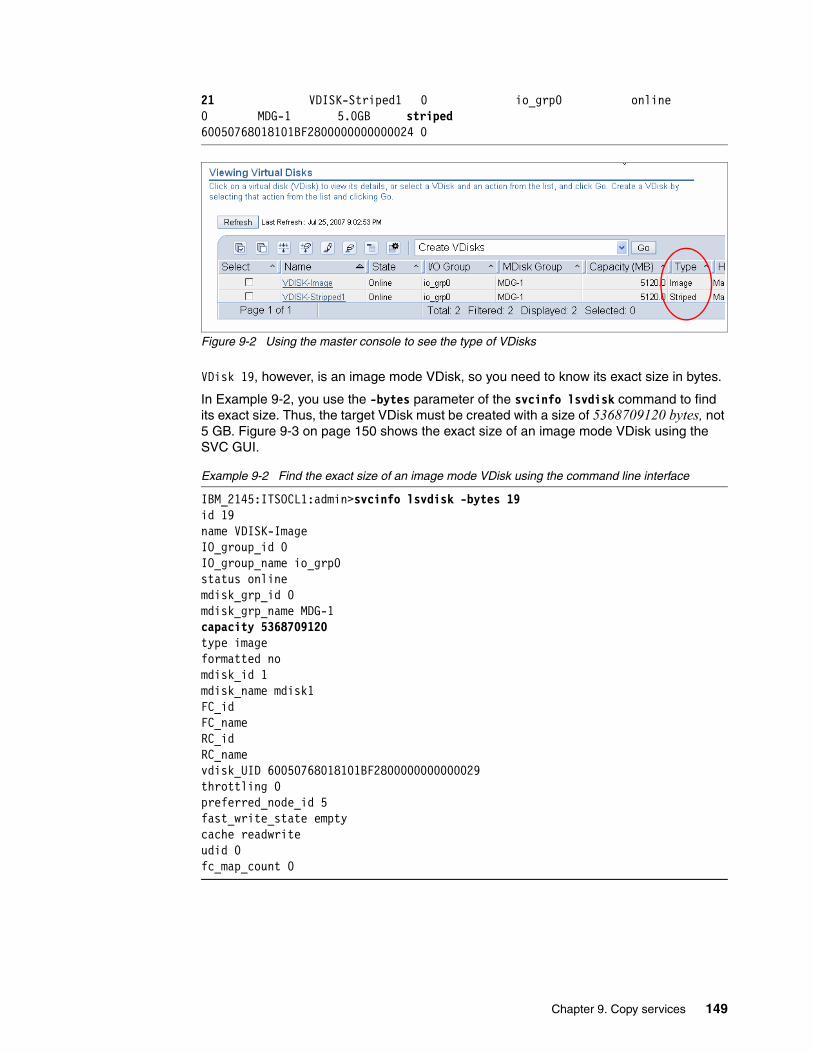
21 VDISK-Striped1 0 io_grp0 online 0 MDG-1 5.0GB striped 60050768018101BF2800000000000024 0
Figure 9-2 Using the master console to see the type of VDisks
VDisk 19, however, is an image mode VDisk, so you need to know its exact size in bytes.
In Example 9-2, you use the -bytes parameter of the svcinfo lsvdisk command to find its exact size. Thus, the target VDisk must be created with a size of 5368709120 bytes, not 5 GB. Figure 9-3 on page 150 shows the exact size of an image mode VDisk using the SVC GUI.
Example 9-2 Find the exact size of an image mode VDisk using the command line interface
IBM_2145:ITSOCL1:admin>svcinfo lsvdisk -bytes 19id 19name VDISK-ImageIO_group_id 0IO_group_name io_grp0status onlinemdisk_grp_id 0mdisk_grp_name MDG-1capacity 5368709120type imageformatted nomdisk_id 1mdisk_name mdisk1FC_idFC_nameRC_idRC_namevdisk_UID 60050768018101BF2800000000000029throttling 0preferred_node_id 5fast_write_state emptycache readwriteudid 0fc_map_count 0
Chapter 9. Copy services 149
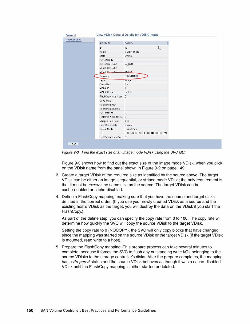
Figure 9-3 Find the exact size of an image mode VDisk using the SVC GUI
Figure 9-3 shows how to find out the exact size of the image mode VDisk, when you click on the VDisk name from the panel shown in Figure 9-2 on page 149.
3. Create a target VDisk of the required size as identified by the source above. The target VDisk can be either an image, sequential, or striped mode VDisk; the only requirement is that it must be exactly the same size as the source. The target VDisk can be cache-enabled or cache-disabled.
4. Define a FlashCopy mapping, making sure that you have the source and target disks defined in the correct order. (If you use your newly created VDisk as a source and the existing host’s VDisk as the target, you will destroy the data on the VDisk if you start the FlashCopy.)
As part of the define step, you can specify the copy rate from 0 to 100. The copy rate will determine how quickly the SVC will copy the source VDisk to the target VDisk.
Setting the copy rate to 0 (NOCOPY), the SVC will only copy blocks that have changed since the mapping was started on the source VDisk or the target VDisk (if the target VDisk is mounted, read write to a host).
5. Prepare the FlashCopy mapping. This prepare process can take several minutes to complete, because it forces the SVC to flush any outstanding write I/Os belonging to the source VDisks to the storage controller’s disks. After the prepare completes, the mapping has a Prepared status and the source VDisk behaves as though it was a cache-disabled VDisk until the FlashCopy mapping is either started or deleted.
150 SAN Volume Controller: Best Practices and Performance Guidelines

6. After the FlashCopy mapping is prepared, you can then quiesce the host by forcing the host and the application to stop I/Os and flush any outstanding write I/Os to disk. This process will be different for each application and for each operating system.
One guaranteed way to quiesce the host is to stop the application and unmount the VDisk from the host.
7. As soon as the host completes its flushing, you can the start the FlashCopy mapping. The FlashCopy starts very quickly (at most, a few seconds).
8. When the FlashCopy mapping has started, you can the unquiesce your application (or mount the volume and start the application), at which point the cache is re-enabled for the source VDisks. The FlashCopy continues to run in the background and ensures that the target VDisk is an exact copy of the source VDisk when the FlashCopy mapping was started.
Steps 1 on page 148 through 5 on page 150 can be performed while the host that owns the source VDisk performs its typical daily activities (that is, no downtime). While step 5 on page 150 is running, which can last several minutes, there might be a delay in I/O throughput, because the cache on the VDisk is temporarily disabled.
Step 6 must be performed when the application is down. However, these steps complete quickly and application downtime is minimal.
The target FlashCopy VDisk can now be assigned to another host and it can be used for read or write, even though the FlashCopy process has not completed.
9.3.2 Making multiple related FlashCopy VDisks with data integrity
Where a host has more than one VDisk, and those VDisks are used by one application, FlashCopy consistency might need to be performed across all disks at exactly the same moment in time to preserve data integrity.
Here are examples when this situation might apply:
� A Windows Exchange server has more than one drive, and each drive is used for an Exchange Information Store. For example, the exchange server has a D drive, an E drive, and an F drive. Each drive is an SVC VDisk that is used to store different information stores for the Exchange server.
Note: If you create a FlashCopy mapping, where the source VDisk is a target VDisk of an active Metro Mirror relationship, this adds additional latency to that existing Metro Mirror relationship (and possibly affects the host that is using the source VDisk of that Metro Mirror relationship as a result).
The reason for the additional latency is that the FlashCopy prepare disables the cache on the source VDisk (which is the target VDisk of the Metro Mirror relationship), and thus, all write I/Os from the Metro Mirror relationship need to commit to the storage controller before the complete is returned to the host.
Note: If you intend to use the target VDisk on the same host as the source VDisk at the same time that the source VDisk is visible to that host, you might need to perform additional preparation steps to enable the host to access VDisks that are identical.
Chapter 9. Copy services 151

Thus, when performing a “snap copy” of the exchange environment, all three disks need to be flashed at exactly the same time, so that if they were used during a recovery, no one information store has more recent data on it than another information store.
� A UNIX® relational database has several VDisks to hold different parts of the relational database. For example, two VDisks are used to hold two distinct tables, and a third VDisk holds the relational database transaction logs.
Again, when a snap copy of the relational database environment is taken, all three disks need to be in sync. That way, when they are used in a recovery, the relational database is not missing any transactions that might have occurred if each VDisk was flashcopied independently.
Here are the steps to ensure that data integrity is preserved when VDisks are related to each other:
1. Your host is currently writing to the VDisks as part of its daily activities. These VDisks will become the source VDisks in our FlashCopy mappings.
2. Identify the size and type (image, sequential, or striped) of each source VDisk. If any of the source VDisks is an image mode VDisk, you will need to know its size in bytes. If any are sequential or striped mode VDisks, their size as reported by the SVC master console or SVC command line will be sufficient.
3. Create a target VDisk of the required size for each source identified in the previous step. The target VDisk can be either an image, sequential, or striped mode VDisk; the only requirement is that they must be exactly the same size as their source. The target VDisk can be cache-enabled or cache-disabled.
4. Define a FlashCopy Consistency Group. This Consistency Group will be linked to each FlashCopy mapping that you have defined, so that data integrity is preserved between each VDisk.
5. Define a FlashCopy mapping for each source VDisk, making sure that you have the source and target disks defined in the correct order. (If you use any of your newly created VDisks as a source and the existing host’s VDisk as the target, you will destroy the data on the VDisk if you start the FlashCopy.)
When defining the mapping, make sure that you link this mapping to the FlashCopy Consistency Group that you defined in the previous step.
As part of the define step, you can specify the copy rate from 0 to 100. The copy rate will determine how quickly the SVC will copy the source VDisks to the target VDisks. Setting the copy rate to 0 (NOCOPY), the SVC will only copy blocks that have changed on any VDisk since the Consistency Group was started on the source VDisk or the target VDisk (if the target VDisk is mounted read/write to a host).
6. Prepare the FlashCopy Consistency Group. This prepare process can take several minutes to complete, because it forces the SVC to flush any outstanding write I/Os belonging to the VDisks in the Consistency Group to the storage controller’s disks. After the prepare completes, the Consistency Group has a Prepared status and all source VDisks behave as though they were cache-disabled VDisks until the Consistency Group is either started or deleted.
152 SAN Volume Controller: Best Practices and Performance Guidelines

7. After the Consistency Group is prepared, you can then quiesce the host by forcing the host and the application to stop I/Os and flush any outstanding write I/Os to disk. This process differs for each application and for each operating system.
One guaranteed way to quiesce the host is to stop the application and unmount the VDisks from the host.
8. As soon as the host completes its flushing, you can the start the Consistency Group. The FlashCopy start completes very quickly (at most, a few seconds).
9. When the Consistency Group has started, you can then unquiesce your application (or mount the VDisks and start the application), at which point the cache is re-enabled. The FlashCopy continues to run in the background and preserves the data that existed on the VDisks when the Consistency Group was started.
Steps 1 on page 152 through 6 on page 152 can be performed while the host that owns the source VDisks is performing its typical daily duties (that is, no downtime). While step 6 on page 152 is running, which can be several minutes, there might be a delay in I/O throughput, because the cache on the VDisks is temporarily disabled.
Step 7 must be performed when the application is down; however, these steps complete quickly so that application downtime is minimal.
The target FlashCopy VDisks can now be assigned to another host and used for read or write even though the FlashCopy processes have not completed.
9.3.3 Creating multiple identical copies of a VDisk
With SVC 4.2, a new feature was introduced that enables you to create multiple point-in-time copies of a source VDisk. These point-in-time copies can be made at different times (for example, hourly) so that an image of a VDisk can be captured before a previous image had completed.
If there is a requirement to have more than one VDisk copy created at exactly the same time, using FlashCopy consistency groups is the best method.
By placing the FlashCopy mappings into a consistency group (where each mapping uses the same source VDisks), when the FlashCopy consistency group is started, each target will be an identical image of all the other VDisk FlashCopy targets.
Note: If you create a FlashCopy mapping where the source VDisk is a target VDisk of an active Metro Mirror relationship, this adds additional latency to that existing Metro Mirror relationship (and possibly affects the host that is using the source VDisk of that Metro Mirror relationship as a result).
The reason for the additional latency is that the FlashCopy Consistency Group prepare disables the cache on all source VDisks (which might be target VDisks of a Metro Mirror relationship), and thus, all write I/Os from the Metro Mirror relationship need to commit to the storage controller before the complete is returned to the host.
Note: If you intend to use any of the target VDisks on the same host as their source VDisk at the same time that the source VDisk is visible to that host, you might need to perform additional preparation steps to enable the host to access VDisks that are identical.
Chapter 9. Copy services 153
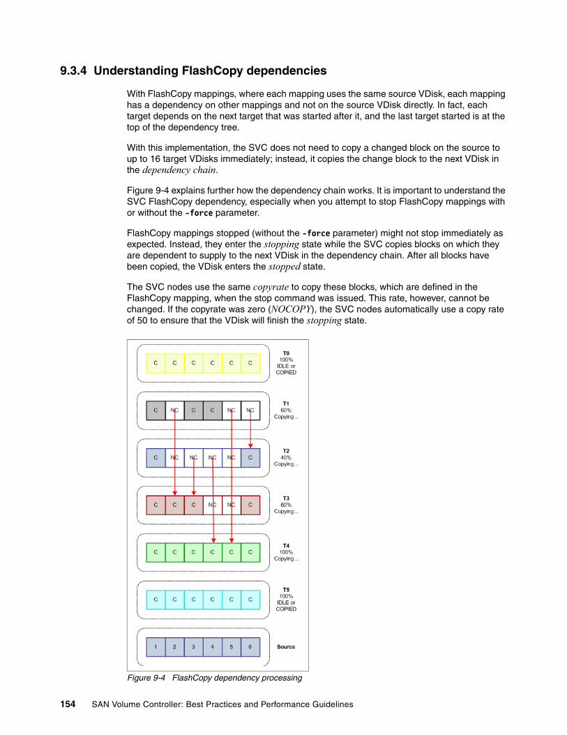
9.3.4 Understanding FlashCopy dependencies
With FlashCopy mappings, where each mapping uses the same source VDisk, each mapping has a dependency on other mappings and not on the source VDisk directly. In fact, each target depends on the next target that was started after it, and the last target started is at the top of the dependency tree.
With this implementation, the SVC does not need to copy a changed block on the source to up to 16 target VDisks immediately; instead, it copies the change block to the next VDisk in the dependency chain.
Figure 9-4 explains further how the dependency chain works. It is important to understand the SVC FlashCopy dependency, especially when you attempt to stop FlashCopy mappings with or without the -force parameter.
FlashCopy mappings stopped (without the -force parameter) might not stop immediately as expected. Instead, they enter the stopping state while the SVC copies blocks on which they are dependent to supply to the next VDisk in the dependency chain. After all blocks have been copied, the VDisk enters the stopped state.
The SVC nodes use the same copyrate to copy these blocks, which are defined in the FlashCopy mapping, when the stop command was issued. This rate, however, cannot be changed. If the copyrate was zero (NOCOPY), the SVC nodes automatically use a copy rate of 50 to ensure that the VDisk will finish the stopping state.
Figure 9-4 FlashCopy dependency processing
154 SAN Volume Controller: Best Practices and Performance Guidelines

In Figure 9-4 on page 154, six FlashCopy mappings have been created from the same VDisk source and started one after another. Thus, mapping T0 started first, followed by T1, then T2, and so on, and T5 was the last FlashCopy mapping started. The time between starting each FlashCopy mapping is not important in this example.
This source VDisk has been divided into six units, and a write to any unit (in either the source or the target VDisk) causes that not yet copied unit to be copied to the target before the write completes to the VDisk. NC (not copied) in the diagram indicates that the block has not yet been copied, while C (copied) indicates that the block has been copied from the source.
Assuming that not all targets have completed yet, T5 was the latest FlashCopy mapping started. It is at the top of the dependency tree. Any writes to a block on the source VDisk that have not yet been copied to another target are written to T5. T4 then gets this block from T5, T3 gets it from T4, and so on until T0 gets the block from T1.
If the next VDisk in the dependency chain does not have a block that is required, the SVC skips to the next VDisk in the chain to get the block or finally gets it from the source if no other VDisk has it. For example in Figure 9-4 on page 154, if a write went to target T1 block 5, the SVC in fact first copies this block from T4, because T2 and T3 do not have it yet.
Each FlashCopy mapping can have different copy rates, so it is possible that each mapping completes at different times. In Figure 9-4 on page 154, mappings T0, T4, and T5 have completed, because they have copied all the changed blocks since the FlashCopy mapping started.
T5 has completed, and because it was started last, it does not depend on any other target VDisk. Normally, T4 is dependent on T5, but it has completed also, so the FlashCopy mapping for T5 has finished. This mapping can be deleted (or is deleted automatically if that parameter was set when it was created).
T4 has also completed; however, mapping T3 has some non-copied blocks and it depends on getting them from T4. T4 will show 100% and a status of copying until T3 gets all its required blocks.
If mapping T4 was stopped, the SVC immediately copies blocks 4 and 5 to T3 to fulfill the dependency. Then, T4 becomes idle_or_copied. This mapping is automatically deleted if this parameter was used on the FlashCopy mapping.
If mapping T4 was stopped with the -force parameter, the relationship stops as normal (because it has reached 100%) and the target is still available. T3, however, does not get its blocks from T4 and enters the stopped state, and T3’s target VDisk goes offline.
Mapping T3 is both dependent on T4 and being depended on by T2. This mapping is in the usual state of copying. If T3 was stopped, blocks 2 and 3 from T3 are copied to T2. T2 has its dependency changed to now become dependent on T4 (to get its remaining blocks). T3 then becomes stopped as normal.
Mapping T1 depends on getting its changed blocks from T2. It is not dependent on T0 (because T0 has finished) so if this mapping is stopped, it stops immediately.
Mapping T0 has completed. Because it was the first mapping started, it has no VDisk dependent on it; therefore, it enters the idle_or_copied state as soon as it finishes.
In summary, when stopping FlashCopy mappings, where the source VDisk is being used in other FlashCopy mappings, remember that the stop request might in fact generate some additional I/O before the FlashCopy mapping finally stops.
Chapter 9. Copy services 155

9.3.5 Using FlashCopy with your backup application
If you are using FlashCopy together with your backup application and you do not intend to keep the target disk after the backup has completed, we recommend that you create the FlashCopy mappings using a NOCOPY rate.
With the NOCOPY rate, the SVC copies blocks that change on the source that are not already on the target to the target, because they have changed. If a read on the target occurs when a block has not yet occurred, the read is automatically fulfilled using the source VDisk.
Thus, using anything other than NOCOPY adds unnecessary additional I/O activity to your SVC cluster and storage subsystem.
If you intend to keep the target so that you can use it as part of a quick recovery process, you might choose one of the following options:
� Create the FlashCopy mapping with NOCOPY initially. If the target is used and migrated into production, you can change the copy rate at the appropriate time with the appropriate rate to have all the data copied to the target disk. When the copy completes, the FlashCopy mapping can be deleted and the source VDisk deleted, freeing the space.
� Create the FlashCopy mapping with a low copy rate. Using a low rate might enable the copy to complete without an impact to your storage controller, thus, leaving bandwidth available for production work. If the target is used and migrated into production, you can change the copy rate to a higher value at the appropriate time to ensure that all data is copied to the target disk. After the copy completes, the source can be deleted, freeing the space.
� Create the FlashCopy with a high copy rate. While this copy rate might add additional I/O burden to your storage controller, it ensures that you get a complete copy of the source disk as quickly as possible.
By using the target on a different MDG, which, in turn, uses a different array or controller, you reduce your window of risk if the storage providing the source disk becomes unavailable.
With SVC 4.2 providing multiple target FlashCopy, you can now use a combination of these methods. For example, you can use the NOCOPY rate for an hourly snapshot of a VDisk with a daily FlashCopy using a high copy rate.
9.3.6 Using FlashCopy to help with migration
SVC FlashCopy can help you with data migration, especially if you want to migrate from an unsupported controller (and your own testing reveals that the SVC can communicate with the device). Another reason is to keep a copy of your data behind on the old controller in order to help with a back-out plan in the event that you want to stop the migration and revert back to the original configuration.
In this example, you can use the following steps to help migrate to a new storage environment with minimum downtime, which enables you to leave a copy of the data in the old environment if you need to back up to the old configuration.
Note: Attaching unsupported controllers to the SVC can lead to data loss, and you might not be supported by IBM. So if you need to attach unsupported controllers, ensure that you have done tested extensively before using this unsupported controller on production data.
156 SAN Volume Controller: Best Practices and Performance Guidelines
To use FlashCopy to help with migration:
1. Your hosts are using the storage from either an unsupported controller or a supported controller that you plan on retiring.
2. Install the new storage into your SAN fabric and define your arrays and LUNs. Do not mask the LUNs to any host; you will mask them to the SVC later.
3. Install the SVC into your SAN fabric and create the required SAN zones for the SVC nodes and SVC to see the new storage.
4. Mask the LUNs from your new storage controller to the SVC, and use svctask detectmdisk on the SVC to discover the new LUNs as MDisks.
5. Place the MDisks into the appropriate MDG.
6. Zone the hosts to the SVC (while maintaining their current zone to their storage) so that you can discover and define the hosts to the SVC.
7. At an appropriate time, install the IBM SDD onto the hosts that will soon use the SVC for storage. If you have performed testing to ensure that the host can use both SDD and the original driver, this step can be done anytime before the next step.
8. Quiesce or shut down the hosts so that they no longer use the old storage.
9. Change the masking on the LUNs on the old storage controller so that the SVC now is the only user of the LUNs. You can change this masking one LUN at a time so that you can discover them (in the next step) one at a time and not mix any LUNs up.
10.Use svctask detectmdisk to discover the LUNs as MDisks. We recommend that you also use svctask chmdisk to rename the LUNs to something more meaningful.
11.Define a VDisk from each LUN and note its exact size (to the number of bytes) by using the svcinfo lsvdisk command.
12.Define a FlashCopy mapping and start the FlashCopy mapping for each VDisk by using the steps in “Steps to making a FlashCopy VDisk with application data integrity” on page 148.
13.Assign the target VDisks to the hosts and then restart your hosts. Your host sees the original data with the exception that the storage is now an IBM SVC LUN.
With these steps, you have made a copy of the existing storage, and the SVC has not been configured to write to the original storage. Thus, if you encounter any problems with these steps, you can reverse everything that you have done, assign the old storage back to the host, and continue without the SVC.
By using FlashCopy in this example, any incoming writes go to the new storage subsystem and any read requests that have not been copied to the new subsystem automatically come from the old subsystem (the FlashCopy source).
You can alter the FlashCopy copy rate, as appropriate, to ensure that all the data is copied to the new controller.
After the FlashCopy completes, you can delete the FlashCopy mappings and the source VDisks. After all the LUNs have been migrated across, you can remove the old storage controller from the SVC node zones and then, optionally, remove the old storage controller from the SAN fabric.
You can also use this process if you want to migrate to a new storage controller and not keep the SVC after the migration. At step 2, make sure that you create LUNs that are the same size as the original LUNs. Then, at step 11, use image mode VDisks. When the FlashCopy mappings complete, you can shut down the hosts and map the storage directly to them, remove the SVC, and continue on the new storage controller.
Chapter 9. Copy services 157
9.3.7 Summary of FlashCopy rules
To summarize the FlashCopy rules:
� FlashCopy services can only be provided inside an SVC cluster. If you want to FlashCopy to remote storage, the remote storage needs to be defined locally to the SVC cluster.
� To maintain data integrity, ensure that all application and host I/Os are flushed from any application and operating system buffers.
� You might need to stop your application in order for it to be “restarted” with a copy of the VDisk that you make. Check with your application vendor if you have any doubts.
� Be careful if you want to map the target flash copied VDisk to the same host that already has the source VDisk mapped to it. Check that your operating system supports this configuration.
� The target VDisk must be the same size as the source VDisk; however, the target VDisk can be a different type (image, striped, or sequential mode) or have different cache settings (cache-enabled or cache-disabled).
� If you stop a FlashCopy mapping or a consistency group before it has completed, you will lose access to the target VDisks. If the target VDisks are mapped to hosts, they will have I/O errors.
� A VDisk cannot be a source in one FlashCopy mapping and a target in another FlashCopy mapping.
� A VDisk can be the source for up to 16 targets.
� A FlashCopy target cannot be used in a Metro Mirror or Global Mirror relationship.
9.4 Metro Mirror and Global Mirror
In the following topics, we discuss Metro Mirror and Global Mirror guidelines and best practices.
9.4.1 Configuration requirements for long distance links
IBM has tested a number of Fibre Channel extender and SAN router technologies for use with the SVC.
The list of supported SAN routers and Fibre Channel extenders is available at this Web site:
http://www.ibm.com/storage/support/2145
If you use one of these extenders or routers, you need to test the link to ensure that the following requirements are met before you place SVC traffic onto the link:
� For SVC 4.1.0.x, the round-trip latency between sites must not exceed 68 ms (34 ms one- way) for Fibre Channel (FC) extenders or 20 ms (10 ms one-way) for SAN routers.
� For SVC 4.1.1.x and later, the round-trip latency between sites must not exceed 80 ms (40 ms one-way).
The latency of long distance links is dependent on the technology that is used. Typically, for each 100 km of distance, it is assumed that 1 ms is added to the latency. Thus, for Global Mirror, this means that the remote cluster can be up to 4000 km away.
� When testing your link for latency, it is important that you take into consideration both current and future expected workloads, including any times when the workload might be
158 SAN Volume Controller: Best Practices and Performance Guidelines

unusually high. The peak workload must be evaluated by considering the average write workload over a period of one minute or less plus the required synchronization copy bandwidth.
� SVC uses some of the bandwidth for its internal SVC inter-cluster heartbeat. The amount of traffic depends on how many nodes are in each of the two clusters. Table 9-2 shows the amount of traffic, in megabits per second, generated by different sizes of clusters.
These numbers represent the total traffic between the two clusters, when no I/O is taking place to mirrored VDisks. Half of the data is sent by one cluster, and half of the data is sent by the other cluster. The traffic will be divided evenly over all available inter-cluster links; therefore, if you have two redundant links, half of this traffic will be sent over each link during fault- free operation.
Table 9-2 SVC inter-cluster heartbeat traffic (Megabits per second)
� If the link between the sites is configured with redundancy so that it can tolerate single failures, the link must be sized so that the bandwidth and latency statements continue to be accurate even during single failure conditions.
9.4.2 Global mirror guidelines
When using SVC Global Mirror, all components in the SAN (switches, remote links, and storage controllers) must be capable of sustaining the workload generated by application hosts, as well as the Global Mirror background copy workload.
If this is not true, Global Mirror might automatically stop your relationships to protect your application hosts from increased response times.
The Global Mirror partnership’s background copy rate must be set to a value appropriate to the link and secondary back-end storage.
Global Mirror is not supported for cache-disabled VDisks participating in a Global Mirror relationship.
We recommend that you use a SAN performance monitoring tool, such as IBM TotalStorage Productivity Center (TPC), which allows you to continuously monitor the SAN components for error conditions and performance problems.
TPC can alert you as soon as there is a performance problem or if a Global (or Metro Mirror) link has been automatically suspended by the SVC. If a remote copy relationship remains stopped without intervention, this can severely impact your recovery point objective. Additionally, restarting a link that has been suspended for a long period of time can add additional burden to your links while the synchronization catches up.
Local/remote cluster
Two nodes Four nodes Six nodes Eight nodes
Two nodes 2.6 4.0 5.4 6.7
Four nodes 4.0 5.5 7.1 8.6
Six nodes 5.4 7.1 8.8 10.5
Eight nodes 6.7 8.6 10.5 12.4
Chapter 9. Copy services 159
gmlinktolerance parameterThe gmlinktolerance parameter of the remote copy partnership must be set to an appropriate value. The default value of 300 seconds (5 minutes) is appropriate for most clients.
If you plan to perform SAN maintenance that might impact SVC Global Mirror relationships, you must either:
� Pick a maintenance window where application I/O workload is reduced for the duration of the maintenance
� Disable the gmlinktolerance feature or increase the gmlinktolerance value (meaning that application hosts might see extended response times from Global Mirror VDisks)
� Stop the Global Mirror relationships
VDisk preferred nodeGlobal Mirror VDisks must have their preferred nodes evenly distributed between the nodes of the clusters.
The preferred node property of a VDisk helps to balance the I/O load between nodes in that I/O Group. This property is also used by Global Mirror to route I/O between clusters.
The SVC node that receives a write for a VDisk is normally that VDisk’s preferred node. For VDisks in a Global Mirror relationship, that node is also responsible for sending that write to the preferred node of the target VDisk. The primary preferred node is also responsible for sending any writes relating to background copy; again, these writes are sent to the preferred node of the target VDisk.
Each node of the remote cluster has a fixed pool of Global Mirror system resources for each node of the primary cluster. That is, each remote node has a separate queue for I/O from each of the primary nodes. This queue is a fixed size and is the same for every node.
If preferred nodes for the VDisks of the remote cluster are set so that every combination of primary node and secondary node is used, Global Mirror performance will be maximized.
Figure 9-5 on page 161 shows an example of Global Mirror resources that are not optimized. VDisks from the Local Cluster are replicated to the Remote Cluster, where all VDisks with a preferred node of Node 1 are replicated to the Remote Cluster, where the target VDisks also have a preferred node of Node 1.
With this configuration, the Remote Cluster Node 1 resources reserved for Local Cluster Node 2 are not used. Nor are the resources for Local Cluster Node 1 used for Remote Cluster Node 2.
Note: The preferred node for a VDisk cannot be changed after the VDisk is created.
160 SAN Volume Controller: Best Practices and Performance Guidelines
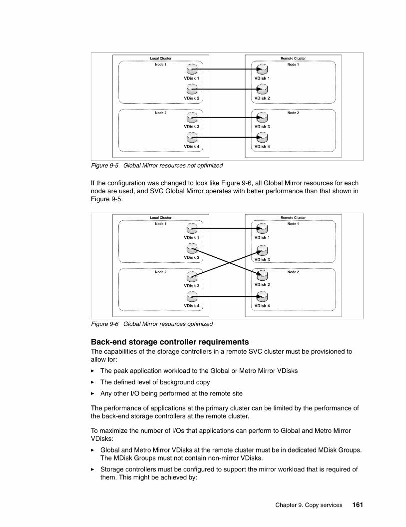
Figure 9-5 Global Mirror resources not optimized
If the configuration was changed to look like Figure 9-6, all Global Mirror resources for each node are used, and SVC Global Mirror operates with better performance than that shown in Figure 9-5.
Figure 9-6 Global Mirror resources optimized
Back-end storage controller requirementsThe capabilities of the storage controllers in a remote SVC cluster must be provisioned to allow for:
� The peak application workload to the Global or Metro Mirror VDisks
� The defined level of background copy
� Any other I/O being performed at the remote site
The performance of applications at the primary cluster can be limited by the performance of the back-end storage controllers at the remote cluster.
To maximize the number of I/Os that applications can perform to Global and Metro Mirror VDisks:
� Global and Metro Mirror VDisks at the remote cluster must be in dedicated MDisk Groups. The MDisk Groups must not contain non-mirror VDisks.
� Storage controllers must be configured to support the mirror workload that is required of them. This might be achieved by:
Chapter 9. Copy services 161

– Dedicating storage controllers to only Global and Metro Mirror VDisks
– Configuring the controller to guarantee sufficient quality of service for the disks used by Global and Metro Mirror
– Ensuring that physical disks are not shared between Global or Metro Mirror VDisks and other I/O.
– Verifying that MDisks within a mirror MDisk group must be similar in their characteristics (for example, RAID level, physical disk count, and disk speed)
9.4.3 Migrating a Metro Mirror relationship to Global Mirror
It is possible to change a Metro Mirror relationship to a Global Mirror relationship or a Global Mirror relationship to a Metro Mirror relationship. This procedure, however, requires an outage to the host and is only successful if you can guarantee that no I/Os are generated to either the source or target VDisks through these steps:
1. Your host is currently running with VDisks that are in a Metro Mirror or Global mirror relationship. This relationship is in the state Consistent-Synchronized.
2. Stop the application and the host.
3. Optionally, unmap the VDisks from the host to guarantee that no I/O can be performed on these VDisks. If there are currently outstanding write I/Os in the cache, you might need to wait at least two minutes before you can unmap the VDisks.
4. Stop the Metro Mirror or Global relationship, ensure that the relationship stops with Consistent Stopped.
5. Delete the current Metro Mirror or Global Mirror relationship.
6. Create the new Metro Mirror or Global Mirror relationship. Ensure that you create it as synchronized to stop the SVC from resynchronizing the VDisks. Use the -sync flag with the svctask mkrcrelationship command.
7. Start the new Metro Mirror or Global Mirror relationship.
8. Remap the source VDisks to the host, if you unmapped them in step 3.
9. Start the host and the application.
9.4.4 Recovering from suspended Metro Mirror or Global Mirror relationships
Its important to understand that when a Metro Mirror or Global Mirror relationship is started for the first time, or started after it has been stopped or suspended for any reason, that while the synchronization is “catching up”, the target disk is not in a consistent state until the synchronization completes.
If you attempt to use the target VDisk at any time that a synchronization has started and before it gets to the synchronized state (by stopping the mirror relationship and making the target writable), the VDisk will contain only parts of the source VDisk and must not be used.
Extremely important: If the relationship is not stopped in the consistent state, or if any host I/O takes place between stopping the old Metro Mirror or Global Mirror relationship and starting the new Metro Mirror or Global Mirror relationship, those changes will never be mirrored to the target VDisks. As a result, the data on the source and target VDisks is not exactly the same, and the SVC will be unaware of the inconsistency.
162 SAN Volume Controller: Best Practices and Performance Guidelines

This is particularly important if you have a Global/Metro Mirror relationship running (that is synchronized) and the link fails (thus, the mirror relationship suspends). When you restart the mirror relationship, the target disk will not be usable until the mirror catches up and becomes synchronized again.
Depending on the amount of changes that need to be applied to the target and your bandwidth, this situation will leave you exposed without a usable target VDisk at all until the synchronization completes.
To avoid this exposure, we recommend that you make a FlashCopy of the target VDisks before you restart the mirror relationship. At least this way, you will have a usable target VDisk even if it does contain old data.
9.4.5 Diagnosing and fixing 1920 errors
The SVC generates a 1920 error message whenever a Metro Mirror or Global Mirror relationship has stopped due to poor performance. A 1920 error does not occur during normal operation as long as you use a supported configuration and your SAN fabric links have been sized to suit your workload.
This can be temporary a temporary error, for example, as a result of maintenance, or a permanent error due to hardware failure or unexpectedly higher host I/O workload.
If several 1920 errors have occurred, you must diagnose the cause of the earliest error first.
In order to diagnose the cause of the first error, it is very important that TPC, or your chosen SAN performance analysis tool, is correctly configured and monitoring statistics when the problem occurs. If you use TPC, set TPC to collect available statistics using the lowest collection interval period, which is currently five minutes.
These are the likely reasons for a 1920 error:
� Maintenance caused a change, such as switch or storage controller changes, for example, updating firmware or adding additional capacity.
� The remote link is overloaded. Using TPC, you can check the following metrics to see if the remote link was a cause:
– Look at the total Global Mirror auxiliary VDisk write throughput before the Global Mirror relationships were stopped.
If this is approximately equal to your link bandwidth, it is very likely that your link is overloaded. This might be due to application host I/O or a combination of host I/O and background (synchronization) copy activity.
– Look at the total Global Mirror source VDisk write throughput before the Global Mirror relationships were stopped.
This represents only the I/O performed by the application hosts. If this number approaches the link bandwidth, you might need to either upgrade the link’s bandwidth, reduce the I/O that the application is attempting to perform, or choose to mirror fewer VDisks using Global Mirror.
If, however, the auxiliary disks show much more write I/O than the source VDisks, this suggests a high level of background copy. Try decreasing the Global Mirror partnership’s background copy rate parameter to bring the total application I/O bandwidth and background copy rate within the link’s capabilities.
– Look at the total Global Mirror source VDisk write throughput after the Global Mirror relationships were stopped.
Chapter 9. Copy services 163

If write throughput increases greatly (by 30% or more) when the relationships were stopped, this indicates that the application host was attempting to perform more I/O than the link can sustain. While the Global Mirror relationships are active, the overloaded link causes higher response times to the application host, which decreases the throughput that it can achieve.
After the relationships have stopped, the application host sees lower response times, and you can see the true I/O workload.
In this case, the link bandwidth must be increased, the application host I/O rate must be decreased, or fewer VDisks must be mirrored using Global Mirror.
� The storage controllers at the remote cluster are overloaded. If one or more of the MDisks on a storage controller provides poor service to the SVC cluster, this can cause a 1920 error if this prevents application I/O from proceeding at the rate required by the application host.
If you have followed the specified back-end storage controller requirements, it is most likely that the error has been caused by a decrease in controller performance due to maintenance actions or a hardware failure of the controller.
Use TPC to obtain the back-end write response time for each MDisk at the remote cluster. If the response time for any individual MDisk exhibits a sudden increase of 50 ms or more, or if the response time is higher than 100 ms, this indicates a problem:
– Check the storage controller for error conditions, such as media errors, a failed physical disk, or associated activity, such as RAID array rebuilding.
If there is an error, fix the problem and restart the Global Mirror relationships.
If there is no error, consider whether the secondary controller is capable of processing the required level of application host I/O. It might be possible to improve the performance of the controller by:
• Adding more physical disks to a RAID array
• Changing the RAID level of the array
• Changing the controller’s cache settings (and checking that the cache batteries are healthy, if applicable)
• Changing other controller-specific configuration parameters
� The storage controllers at the primary site are overloaded. Analyze the performance of the primary back-end storage using the same steps you use for the remote back-end storage.
The main effect of bad performance is to limit the amount of I/O that can be performed by application hosts. Therefore, back-end storage at the primary site must be monitored regardless of Global Mirror.
However, if bad performance continues for a prolonged period, it is possible that a 1920 error will occur and the Global Mirror relationships will stop.
� One of the SVC clusters is overloaded. Use TPC to obtain the port to local node send response time and port to local node send queue time.
If the total of these statistics for either cluster is higher than 1 millisecond, this suggests that the SVC might be experiencing a very high I/O load.
Also, check the SVC node CPU utilization; if this figure is in excess of 50%, this might also contribute to the problem.
In either case, contact your IBM service support representative for further assistance.
� FlashCopy mappings are in the prepared state. If the Global Mirror target VDisks are the sources of a FlashCopy mapping, and that mapping is in the prepared state for an extended time, performance to those VDisks can be impacted, because the cache is
164 SAN Volume Controller: Best Practices and Performance Guidelines

disabled. Starting the flash copy mapping will re-enable the cache, improving the VDisks’ performance for Global Mirror I/O.
9.4.6 Using Metro Mirror or Global Mirror with FlashCopy
SVC allows you to use a VDisk in a Metro Mirror or Global Mirror relationship as a source VDisk for a FlashCopy mapping. You cannot use a VDisk as a FlashCopy mapping target that is already in a Metro Mirror or Global Mirror relationship.
When you prepare a FlashCopy mapping, the SVC puts the source VDisks into a temporary cache-disabled state. This temporary state adds additional latency to the Metro Mirror relationship, because I/Os that are normally committed to SVC memory now need to be committed to the storage controller.
One method of avoiding this latency is to temporarily stop the Metro Mirror or Global Mirror relationship before preparing the FlashCopy mapping. When the Metro Mirror or Global Mirror relationship is stopped, the SVC records all changes that occur to the source VDisks and applies those changes to the target when the remote copy mirror is restarted.
9.4.7 Saving bandwidth creating Metro Mirror and Global Mirror relationships
If you have a situation where you have a large source VDisk (or a large number of source VDisks) that you want to replicate to a remote site and your planning shows that the SVC mirror initial sync time will take too long (or will be too costly, if you pay for the traffic that you use), here is a method of setting up the sync using another medium (that might be less expensive).
Another reason that you might want to use these steps is if you want to increase the size of the VDisks currently in a Metro Mirror or Global Mirror relationship. To do this, you must delete the current mirror relationships and redefine the mirror relationships after you have resized the VDisks.
In this example, we use tape media as the source for the initial sync for the Metro Mirror or Global Mirror relationship target before using SVC to maintain the Metro Mirror or Global Mirror. This does not require downtime for the hosts using the source VDisks.
Here are the steps:
1. The hosts are up and running and using their VDisks as normal. There is no Metro Mirror or Global Mirror relationship defined yet.
You have identified all the VDisks that will become the source VDisks in a Metro Mirror or Global Mirror relationship.
2. You have already established the SVC cluster relationship with the target SVC.
3. Define a Metro Mirror or Global Mirror relationship for each source VDisk. When defining the relationship, ensure that you use the -sync option, which stops the SVC from performing an initial sync.
4. Stop each mirror relationship by using the -access option, which enables write access to the target VDisks. We will need this access later.
Note: If you fail to use the -sync option, all of these steps are redundant, because the SVC performs a full initial sync anyway.
Chapter 9. Copy services 165

5. Make a copy of the source VDisk to the alternate media by using the dd command to copy the contents of the VDisk to tape. Another option might be using your backup tool (for example, IBM Tivoli Storage Manager) to make an image backup of the VDisk.
6. Ship your media to the remote site and apply the contents to the targets of the Metro/Global mirror relationship; you can mount the Metro Mirror and Global Mirror target VDisks to a UNIX server and use the dd command to copy the contents of the tape to the target VDisk. If you used your backup tool to make an image of the VDisk, follow the instructions for your tool to restore the image to the target VDisk. Do not forget to remove the mount, if this is a temporary host.
7. Unmount the target VDisks from your host. When you start the Metro Mirror and Global Mirror relationship later, the SVC will stop write access to the VDisk while the mirror relationship is running.
8. Start your Metro Mirror and Global Mirror relationships. While the mirror relationship catches up, the target VDisk is not usable at all. As soon as it reaches Consistent Copying, your remote VDisk is ready for use in a disaster.
9.4.8 Using TPC to monitor Global Mirror performance
It is important to use a SAN performance monitoring tool to ensure that all SAN components perform correctly. While this is useful in any SAN environment, it is particularly important when using an asynchronous mirroring solution, such as SVC Global Mirror. Performance statistics ned to be gathered at the highest possible frequency; for TPC, this is currently five minutes.
Note that if your VDisk or MDisk configuration is changed, you must restart your TPC performance report to ensure that performance is correctly monitored for the new configuration.
If using TPC, monitor:
� Global Mirror Secondary Write Lag
This is intended for monitoring mirror delays (tpcpool metric 942).
� Port to Remote Node Send Response
Time needs to be less than 80 ms (the maximum latency supported by SVC Global Mirror). A number in excess of 80 ms suggests that the long-distance link has excessive latency, which needs to be rectified. One possibility to investigate is that the link is operating at maximum bandwidth (tpcpool metrics 931 and 934).
� Sum of Port to Local Node Send Response Time and Port to Local Node Send Queue
Note: Even though the source is being modified while you are copying the image, the SVC is tracking those changes. Your image that you create might already have some of the changes and is likely to have missed some of the changes as well.
When the relationship is restarted, the SVC will apply all changes that occurred since the relationship was stopped in step 4. After all the changes are applied, you will have a consistent target image.
Note: It will not matter how long it takes to get your media to the remote site and perform this step. The quicker you can get it to the remote site and loaded, the quicker SVC is running and maintaining the Metro Mirror and Global Mirror.
166 SAN Volume Controller: Best Practices and Performance Guidelines

Time must be less than 1 ms for the primary cluster. A number in excess of this might indicate that an I/O Group is reaching its I/O throughput limit, which can limit performance.
� CPU Utilization Percentage
CPU Utilization must be below 50%.
� Sum of Backend Write Response Time and Write Queue Time for Global Mirror MDisks at the remote cluster.
Time needs to be less than 100 ms. A longer response time can indicate that the storage controller is overloaded. If the response time for a specific storage controller is outside of its specified operating range, this must be investigated for the same reason.
� Sum of Backend Write Response Time and Write Queue Time for Global Mirror MDisks at the primary cluster.
Time must also be less than 100 ms. If response time is greater than this, application hosts might see extended response times if the SVC’s cache becomes full.
� Write Data Rate for Global Mirror MDisk groups at the remote cluster.
This data rate indicates the amount of data being written by Global Mirror. If this number approaches either the inter-cluster link bandwidth or the storage controller throughput limit, be aware that further increases can cause overloading of the system and monitor this number appropriately.
9.4.9 Summary of Metro Mirror and Global Mirror rules
To summarize the Metro Mirror and Global Mirror rules:
� FlashCopy targets cannot be in a Metro Mirror or Global Mirror relationship, only FlashCopy sources can be in a Metro Mirror or Global Mirror relationship.
� Metro Mirror or Global Mirror source or target VDisks cannot be moved to different I/O Groups.
� Metro Mirror or Global Mirror VDisks cannot be resized.
� Intra-cluster Metro Mirror or Global Mirror can only mirror between VDisks in the same I/O Group.
� The target VDisks must be the same size as the source VDisks; however, the target VDisk can be a different type (image, striped, or sequential mode) or have different cache settings (cache-enabled or cache-disabled).
Chapter 9. Copy services 167

168 SAN Volume Controller: Best Practices and Performance Guidelines
Chapter 10. Hosts
This chapter describes best practices and monitoring for host systems attached to the San Volume Controller (SVC).
A host system is an Open Systems computer that is connected to the switch through a Fibre Channel (FC) interface.
The most important part of tuning, troubleshooting, and performance considerations for a host attached to an SVC will be in the host. There are three major areas of concern:
� Using multipathing and bandwidth (physical capability of SAN and back-end storage)
� Understanding how your host performs I/O and what types of I/O
� Utilizing measurement and test tools to determine host performance and for tuning
This topic supplements the IBM System Storage SAN Volume Controller Host Attachment User’s Guide Version 4.2.0, SC26-7905, at:
http://www-1.ibm.com/support/docview.wss?rs=591&context=STCWGAV&context=STC7HAC&context=STCWGBP&dc=DA400&q1=english&uid=ssg1S7001712&loc=en_US&cs=utf-8&lang=en
10
© Copyright IBM Corp. 2008. All rights reserved. 169

10.1 Configuration recommendations
There are some basic configuration recommendations when using the SVC to manage storage connected to any host. The considerations include how many paths through the fabric are allocated to the host, how many host ports to use, how to spread the hosts across I/O Groups, logical unit number (LUN) mapping, and the correct size of virtual disks (VDisks) to use.
10.1.1 The number of paths
From general experience, we have determined that it is best to limit the total number of paths from any host to the SVC. We recommend that you limit the total number of paths that the multipathing software on each host is managing to four, even though the maximum supported is eight paths. Following these rules solves many issues with high port fanouts, fabric state changes, and host memory management, and improves performance.
Refer to the following Web site for the latest maximum configuration requirements:
http://www-1.ibm.com/support/docview.wss?rs=591&uid=ssg1S1003093
The major reason to limit the number of paths available to a host from the SVC is for error recovery, failover, and failback purposes. The overall time for handling errors by a host is significantly reduced. Additionally, resources within the host are greatly reduced each time you remove a path from the multipathing management. Two path configurations have just one path to each node. This is a supported configuration but not recommended for most configurations. However, refer to the host attachment guide for specific host and OS requirements.
http://www-1.ibm.com/support/docview.wss?rs=591&context=STCWGAV&context=STC7HAC&context=STCWGBP&dc=DA400&q1=english&uid=ssg1S7001712&loc=en_US&cs=utf-8&lang=en
We have measured the effect of multipathing on performance as shown in the following tables. As the charts show, the differences in performance are generally minimal, but the differences can reduce performance by almost 10% for specific workloads. These numbers were produced with an AIX host running IBM Subsystem Device Driver (SDD) against the 4.2 SVC. The host was tuned specifically for performance by adjusting queue depths and buffers.
We tested a range of reads and writes, random and sequential, cache hits and misses, at 512 byte, 4 KB, and 64 KB transfer sizes.
Table 10-1 shows the effects of multipathing.
Table 10-1 Effect of multipathing on write performance
R/W test Four paths Eight paths Difference
Write Hit 512 b Sequential IOPS
81877 74909 -8.6%
Write Miss 512 b Random IOPS
60510.4 57567.1 -5.0%
70/30 R/W Miss 4K Rdm IOPS
130445.3 124547.9 -5.6%
70/30 R/W Miss 64K Rdm MBps
1810.8138 1834.2696 1.3%
170 SAN Volume Controller: Best Practices and Performance Guidelines

10.1.2 Host ports
The general recommendation for utilizing host ports connected to the SVC is to limit the number of physical ports to two ports on two different physical adapters. Each of these ports will be zoned to one target port in each SVC node, thus limiting the number of total paths to four, preferably on totally separate redundant SAN fabrics.
If four host ports are preferred for maximum redundant paths, the requirement is to zone each host adapter to one SVC target port on each node (for a maximum of eight paths). The benefits of path redundancy are outweighed by the host memory resource utilization required for more paths.
Use one host object to represent a cluster of hosts and use multiple worldwide port names (WWPNs) to represent the ports from all the hosts that will share the same set of VDisks.
10.1.3 Port masking
You can use a port mask to control the node target ports that a host can access. The port mask applies to logins from the host port that are associated with the host object. You can use this capability to simplify the switch zoning by limiting the SVC ports within the SVC configuration, rather than utilizing direct one-to-one zoning within the switch. This capability can simplify zone management.
The port mask is a four-bit field that applies to all nodes in the cluster for the particular host. For example, a port mask of 0001 allows a host to log in to a single port on every SVC node in the cluster, if the switch zone also includes both host and SVC node ports.
10.1.4 Host to I/O Group mapping
An I/O Grouping consists of two SVC nodes that share management of VDisks within a cluster. The recommendation is to utilize a single I/O Group (iogrp) for all VDisks allocated to a particular host. This recommendation has many benefits. One major benefit is the minimization of port fanouts within the SAN fabric. Another benefit is to maximize the potential host attachments to the SVC, because maxima are based on I/O Groups. A third benefit is within the host itself, having fewer target ports to manage.
The number of host ports and host objects allowed per I/O Group is dependent upon the switch fabric type. Refer to the maximum configurations document for these maxima:
http://www-1.ibm.com/support/docview.wss?rs=591&uid=ssg1S1003093
50/50 R/W Miss 4K Rdm IOPS
97822.6 98427.8 0.6%
50/50 R/W Miss 64K Rdm MBps
1674.5727 1678.1815 0.2%
R/W test Four paths Eight paths Difference
Best practice: Though it is supported in theory, we strongly recommend that you keep Fibre Channel tape and Fibre Channel disks on separate host bus adapters (HBAs). These devices have two very different data patterns when operating in their optimum mode, and the switching between them can cause undesired overhead and performance slowdown for the applications.
Chapter 10. Hosts 171
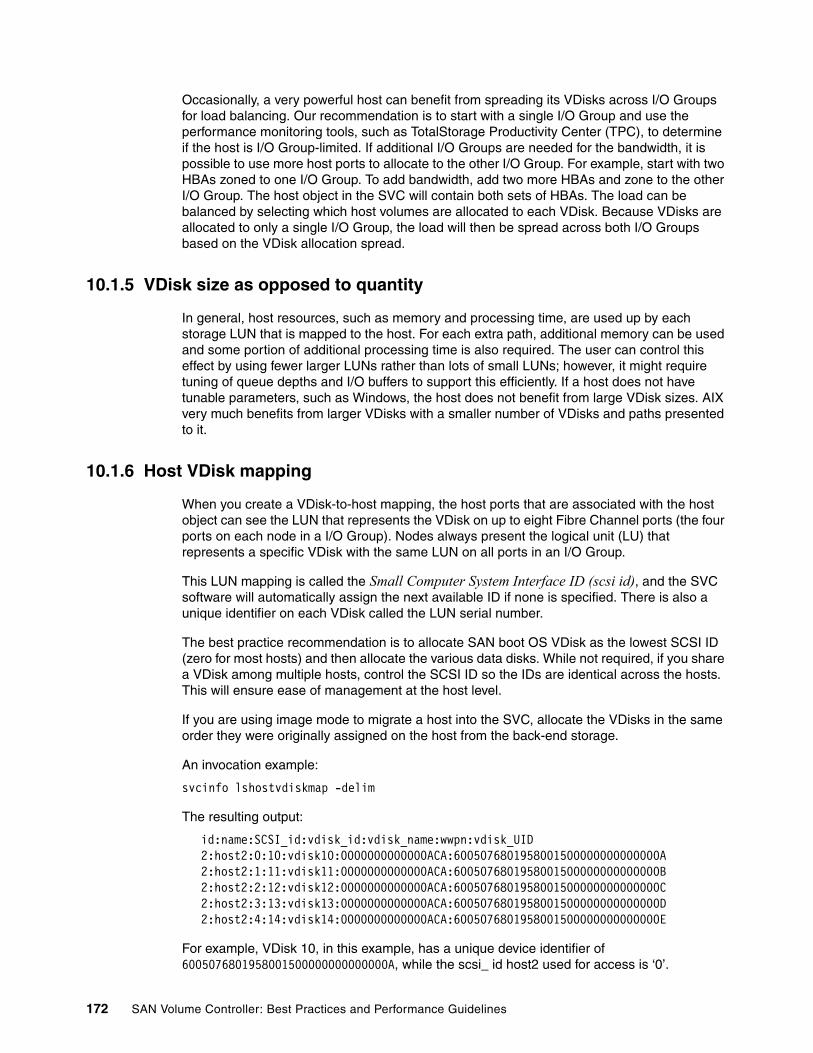
Occasionally, a very powerful host can benefit from spreading its VDisks across I/O Groups for load balancing. Our recommendation is to start with a single I/O Group and use the performance monitoring tools, such as TotalStorage Productivity Center (TPC), to determine if the host is I/O Group-limited. If additional I/O Groups are needed for the bandwidth, it is possible to use more host ports to allocate to the other I/O Group. For example, start with two HBAs zoned to one I/O Group. To add bandwidth, add two more HBAs and zone to the other I/O Group. The host object in the SVC will contain both sets of HBAs. The load can be balanced by selecting which host volumes are allocated to each VDisk. Because VDisks are allocated to only a single I/O Group, the load will then be spread across both I/O Groups based on the VDisk allocation spread.
10.1.5 VDisk size as opposed to quantity
In general, host resources, such as memory and processing time, are used up by each storage LUN that is mapped to the host. For each extra path, additional memory can be used and some portion of additional processing time is also required. The user can control this effect by using fewer larger LUNs rather than lots of small LUNs; however, it might require tuning of queue depths and I/O buffers to support this efficiently. If a host does not have tunable parameters, such as Windows, the host does not benefit from large VDisk sizes. AIX very much benefits from larger VDisks with a smaller number of VDisks and paths presented to it.
10.1.6 Host VDisk mapping
When you create a VDisk-to-host mapping, the host ports that are associated with the host object can see the LUN that represents the VDisk on up to eight Fibre Channel ports (the four ports on each node in a I/O Group). Nodes always present the logical unit (LU) that represents a specific VDisk with the same LUN on all ports in an I/O Group.
This LUN mapping is called the Small Computer System Interface ID (scsi id), and the SVC software will automatically assign the next available ID if none is specified. There is also a unique identifier on each VDisk called the LUN serial number.
The best practice recommendation is to allocate SAN boot OS VDisk as the lowest SCSI ID (zero for most hosts) and then allocate the various data disks. While not required, if you share a VDisk among multiple hosts, control the SCSI ID so the IDs are identical across the hosts. This will ensure ease of management at the host level.
If you are using image mode to migrate a host into the SVC, allocate the VDisks in the same order they were originally assigned on the host from the back-end storage.
An invocation example:
svcinfo lshostvdiskmap -delim
The resulting output:
id:name:SCSI_id:vdisk_id:vdisk_name:wwpn:vdisk_UID 2:host2:0:10:vdisk10:0000000000000ACA:6005076801958001500000000000000A 2:host2:1:11:vdisk11:0000000000000ACA:6005076801958001500000000000000B 2:host2:2:12:vdisk12:0000000000000ACA:6005076801958001500000000000000C 2:host2:3:13:vdisk13:0000000000000ACA:6005076801958001500000000000000D 2:host2:4:14:vdisk14:0000000000000ACA:6005076801958001500000000000000E
For example, VDisk 10, in this example, has a unique device identifier of 6005076801958001500000000000000A, while the scsi_ id host2 used for access is ‘0’.
172 SAN Volume Controller: Best Practices and Performance Guidelines

svcinfo lsvdiskhostmap -delim : EEXCLS_HBin01 id:name:SCSI_id:host_id:host_name:wwpn:vdisk_UID 950:EEXCLS_HBin01:14:109:HDMCENTEX1N1:10000000C938CFDF:600507680191011D4800000000000466 950:EEXCLS_HBin01:14:109:HDMCENTEX1N1:10000000C938D01F:600507680191011D4800000000000466 950:EEXCLS_HBin01:13:110:HDMCENTEX1N2:10000000C938D65B:600507680191011D4800000000000466 950:EEXCLS_HBin01:13:110:HDMCENTEX1N2:10000000C938D3D3:600507680191011D4800000000000466 950:EEXCLS_HBin01:14:111:HDMCENTEX1N3:10000000C938D615:600507680191011D4800000000000466 950:EEXCLS_HBin01:14:111:HDMCENTEX1N3:10000000C938D612:600507680191011D4800000000000466 950:EEXCLS_HBin01:14:112:HDMCENTEX1N4:10000000C938CFBD:600507680191011D4800000000000466 950:EEXCLS_HBin01:14:112:HDMCENTEX1N4:10000000C938CE29:600507680191011D4800000000000466 950:EEXCLS_HBin01:14:113:HDMCENTEX1N5:10000000C92EE1D8:600507680191011D4800000000000466 950:EEXCLS_HBin01:14:113:HDMCENTEX1N5:10000000C92EDFFE:600507680191011D4800000000000466
If using IBM multipathing software (IBM Subsystem Device Driver (SDD) or SDDDSM), the command datapath query device shows the vdisk_UID (unique identifier) and so enables easier management of VDisks. The SDDPCM equivalent command is pcmpath query device.
Host-VDisk mapping from more than one I/O GroupThe SCSI ID field in the host-VDiskmap might not be unique for a VDisk for a host. This is because it does not completely define the uniqueness of the LUN. The target port is also used as part of the identification. If there are two I/O Groups of VDisks assigned to a host port, one set will start with SCSI ID 0 and then be incremented (given the default), and the SCSI ID for the second I/O Group will also start at zero and then increment by default. Refer to Example 10-1 for a sample host map like this. VDisk s-0-6-4 and VDisk s-1-8-2 both have a SCSI ID of ONE, yet they have different LUN serial numbers.
Example 10-1 Host-VDisk mapping for one host from two I/O Groups
IBM_2145:ITSOCL1:admin>svcinfo lshostvdiskmap senegalid name SCSI_id vdisk_id vdisk_name wwpn vdisk_UID0 senegal 1 60 s-0-6-4 210000E08B89CCC2 60050768018101BF28000000000000A80 senegal 2 58 s-0-6-5 210000E08B89CCC2 60050768018101BF28000000000000A90 senegal 3 57 s-0-5-1 210000E08B89CCC2 60050768018101BF28000000000000AA0 senegal 4 56 s-0-5-2 210000E08B89CCC2 60050768018101BF28000000000000AB0 senegal 5 61 s-0-6-3 210000E08B89CCC2 60050768018101BF28000000000000A70 senegal 6 36 big-0-1 210000E08B89CCC2 60050768018101BF28000000000000B90 senegal 7 34 big-0-2 210000E08B89CCC2 60050768018101BF28000000000000BA
Chapter 10. Hosts 173

0 senegal 1 40 s-1-8-2 210000E08B89CCC2 60050768018101BF28000000000000B50 senegal 2 50 s-1-4-3 210000E08B89CCC2 60050768018101BF28000000000000B10 senegal 3 49 s-1-4-4 210000E08B89CCC2 60050768018101BF28000000000000B20 senegal 4 42 s-1-4-5 210000E08B89CCC2 60050768018101BF28000000000000B30 senegal 5 41 s-1-8-1 210000E08B89CCC2 60050768018101BF28000000000000B4
Example 10-2 shows the datapath query device output of this Windows host. Note that the order of the two I/O Groups’ VDisks is reversed from the host-vdisk map. VDisk s-1-8-2 is first, followed by the rest of the LUNs from the second I/O Group, then VDisk s-0-6-4, and the rest of the LUNs from the first I/O Group. Most likely, Windows discovered the second set of LUNS first. However, the relative order within an I/O Group is maintained.
Example 10-2 datapath query device for the host VDisk map
C:\Program Files\IBM\Subsystem Device Driver>datapath query device
Total Devices : 12
DEV#: 0 DEVICE NAME: Disk1 Part0 TYPE: 2145 POLICY: OPTIMIZEDSERIAL: 60050768018101BF28000000000000B5============================================================================Path# Adapter/Hard Disk State Mode Select Errors 0 Scsi Port2 Bus0/Disk1 Part0 OPEN NORMAL 0 0 1 Scsi Port2 Bus0/Disk1 Part0 OPEN NORMAL 1342 0 2 Scsi Port3 Bus0/Disk1 Part0 OPEN NORMAL 0 0 3 Scsi Port3 Bus0/Disk1 Part0 OPEN NORMAL 1444 0
DEV#: 1 DEVICE NAME: Disk2 Part0 TYPE: 2145 POLICY: OPTIMIZEDSERIAL: 60050768018101BF28000000000000B1============================================================================Path# Adapter/Hard Disk State Mode Select Errors 0 Scsi Port2 Bus0/Disk2 Part0 OPEN NORMAL 1405 0 1 Scsi Port2 Bus0/Disk2 Part0 OPEN NORMAL 0 0 2 Scsi Port3 Bus0/Disk2 Part0 OPEN NORMAL 1387 0 3 Scsi Port3 Bus0/Disk2 Part0 OPEN NORMAL 0 0
DEV#: 2 DEVICE NAME: Disk3 Part0 TYPE: 2145 POLICY: OPTIMIZEDSERIAL: 60050768018101BF28000000000000B2============================================================================Path# Adapter/Hard Disk State Mode Select Errors 0 Scsi Port2 Bus0/Disk3 Part0 OPEN NORMAL 1398 0 1 Scsi Port2 Bus0/Disk3 Part0 OPEN NORMAL 0 0 2 Scsi Port3 Bus0/Disk3 Part0 OPEN NORMAL 1407 0 3 Scsi Port3 Bus0/Disk3 Part0 OPEN NORMAL 0 0
DEV#: 3 DEVICE NAME: Disk4 Part0 TYPE: 2145 POLICY: OPTIMIZEDSERIAL: 60050768018101BF28000000000000B3============================================================================Path# Adapter/Hard Disk State Mode Select Errors
174 SAN Volume Controller: Best Practices and Performance Guidelines

0 Scsi Port2 Bus0/Disk4 Part0 OPEN NORMAL 1504 0 1 Scsi Port2 Bus0/Disk4 Part0 OPEN NORMAL 0 0 2 Scsi Port3 Bus0/Disk4 Part0 OPEN NORMAL 1281 0 3 Scsi Port3 Bus0/Disk4 Part0 OPEN NORMAL 0 0
DEV#: 4 DEVICE NAME: Disk5 Part0 TYPE: 2145 POLICY: OPTIMIZEDSERIAL: 60050768018101BF28000000000000B4============================================================================Path# Adapter/Hard Disk State Mode Select Errors 0 Scsi Port2 Bus0/Disk5 Part0 OPEN NORMAL 0 0 1 Scsi Port2 Bus0/Disk5 Part0 OPEN NORMAL 1399 0 2 Scsi Port3 Bus0/Disk5 Part0 OPEN NORMAL 0 0 3 Scsi Port3 Bus0/Disk5 Part0 OPEN NORMAL 1391 0
DEV#: 5 DEVICE NAME: Disk6 Part0 TYPE: 2145 POLICY: OPTIMIZEDSERIAL: 60050768018101BF28000000000000A8============================================================================Path# Adapter/Hard Disk State Mode Select Errors 0 Scsi Port2 Bus0/Disk6 Part0 OPEN NORMAL 1400 0 1 Scsi Port2 Bus0/Disk6 Part0 OPEN NORMAL 0 0 2 Scsi Port3 Bus0/Disk6 Part0 OPEN NORMAL 1390 0 3 Scsi Port3 Bus0/Disk6 Part0 OPEN NORMAL 0 0
DEV#: 6 DEVICE NAME: Disk7 Part0 TYPE: 2145 POLICY: OPTIMIZEDSERIAL: 60050768018101BF28000000000000A9============================================================================Path# Adapter/Hard Disk State Mode Select Errors 0 Scsi Port2 Bus0/Disk7 Part0 OPEN NORMAL 1379 0 1 Scsi Port2 Bus0/Disk7 Part0 OPEN NORMAL 0 0 2 Scsi Port3 Bus0/Disk7 Part0 OPEN NORMAL 1412 0 3 Scsi Port3 Bus0/Disk7 Part0 OPEN NORMAL 0 0
DEV#: 7 DEVICE NAME: Disk8 Part0 TYPE: 2145 POLICY: OPTIMIZEDSERIAL: 60050768018101BF28000000000000AA============================================================================Path# Adapter/Hard Disk State Mode Select Errors 0 Scsi Port2 Bus0/Disk8 Part0 OPEN NORMAL 0 0 1 Scsi Port2 Bus0/Disk8 Part0 OPEN NORMAL 1417 0 2 Scsi Port3 Bus0/Disk8 Part0 OPEN NORMAL 0 0 3 Scsi Port3 Bus0/Disk8 Part0 OPEN NORMAL 1381 0
DEV#: 8 DEVICE NAME: Disk9 Part0 TYPE: 2145 POLICY: OPTIMIZEDSERIAL: 60050768018101BF28000000000000AB============================================================================Path# Adapter/Hard Disk State Mode Select Errors 0 Scsi Port2 Bus0/Disk9 Part0 OPEN NORMAL 0 0 1 Scsi Port2 Bus0/Disk9 Part0 OPEN NORMAL 1388 0 2 Scsi Port3 Bus0/Disk9 Part0 OPEN NORMAL 0 0 3 Scsi Port3 Bus0/Disk9 Part0 OPEN NORMAL 1413 0
DEV#: 9 DEVICE NAME: Disk10 Part0 TYPE: 2145 POLICY: OPTIMIZEDSERIAL: 60050768018101BF28000000000000A7=============================================================================Path# Adapter/Hard Disk State Mode Select Errors 0 Scsi Port2 Bus0/Disk10 Part0 OPEN NORMAL 1293 0
Chapter 10. Hosts 175

1 Scsi Port2 Bus0/Disk10 Part0 OPEN NORMAL 0 0 2 Scsi Port3 Bus0/Disk10 Part0 OPEN NORMAL 1477 0 3 Scsi Port3 Bus0/Disk10 Part0 OPEN NORMAL 0 0
DEV#: 10 DEVICE NAME: Disk11 Part0 TYPE: 2145 POLICY: OPTIMIZEDSERIAL: 60050768018101BF28000000000000B9=============================================================================Path# Adapter/Hard Disk State Mode Select Errors 0 Scsi Port2 Bus0/Disk11 Part0 OPEN NORMAL 0 0 1 Scsi Port2 Bus0/Disk11 Part0 OPEN NORMAL 59981 0 2 Scsi Port3 Bus0/Disk11 Part0 OPEN NORMAL 0 0 3 Scsi Port3 Bus0/Disk11 Part0 OPEN NORMAL 60179 0
DEV#: 11 DEVICE NAME: Disk12 Part0 TYPE: 2145 POLICY: OPTIMIZEDSERIAL: 60050768018101BF28000000000000BA=============================================================================Path# Adapter/Hard Disk State Mode Select Errors 0 Scsi Port2 Bus0/Disk12 Part0 OPEN NORMAL 28324 0 1 Scsi Port2 Bus0/Disk12 Part0 OPEN NORMAL 0 0 2 Scsi Port3 Bus0/Disk12 Part0 OPEN NORMAL 27111 0 3 Scsi Port3 Bus0/Disk12 Part0 OPEN NORMAL 0 0
Sometimes, a host might discover everything correctly at initial configuration, but it does not keep up with the dynamic changes in the configuration. The scsi id is therefore very important. 10.2.4, “Dynamic reconfiguration” on page 179 will discuss this topic further.
10.1.7 Server adapter layout
If your host system has multiple internal I/O busses, place the two adapters used for SVC cluster access on two different I/O busses to maximize availability and performance.
10.1.8 Availability as opposed to error isolation
It is important to balance availability via the multiple paths through a SAN to the two SVC nodes as opposed to error isolation. Normally, people add more paths to a SAN to increase availability. This leads to the conclusion that you want all four ports in each node zoned to each port in the host. However, our experience has shown that it is better to limit the number of paths so that the software error recovery software within a switch or a host is able to manage loss of paths quickly and efficiently. Therefore, it is beneficial to keep the span out from the host port through the SAN to an SVC port to one-to-one as much as possible. Limit each host port to a different set of SVC ports on each node. This will keep the errors within a host isolated to a single adapter if the errors are coming from a single SVC port or from one fabric, making isolation to a failing port or switch easier.
10.2 Host pathing
Each host mapping associates a VDisk with a host object and allows all HBA ports in thehost object to access the VDisk. You can map a VDisk to multiple host objects. When a mapping is created, multiple paths might exist across the SAN fabric from the hosts to the SVC nodes that are presenting the VDisk. Most operating systems present each path to a VDisk as a separate storage device. The SVC, therefore, requires that multipathing software
176 SAN Volume Controller: Best Practices and Performance Guidelines

is running on the host. The multipathing software manages the many paths that are available to the VDisk and presents a single storage device to the operating system.
10.2.1 Preferred path algorithm
I/O traffic for a particular VDisk is, at any one time, managed exclusively by the nodes in a single I/O Group. The distributed cache in the SAN Volume Controller is two-way. When a VDisk is created, a preferred node is chosen. This is controllable at the time of creation. The owner node for a VDisk is the preferred node when both nodes are available.
When I/O is performed to a VDisk, the node that processes the I/O duplicates the data onto the partner node that is in the I/O Group. A write from the SVC node to the back-end managed disk (MDisk) is only destaged via the owner node (normally, the preferred node). Therefore, when a new write or read comes in on the non-owner node, it has to send some extra messages to the owner-node to check if it has the data in cache, or if it is in the middle of destaging that data. Therefore, performance will be enhanced by accessing the VDisk through the preferred node.
IBM multipathing software (SDD, SDDPCM, or SDDDSM) will check the preferred path setting during initial configuration for each VDisk and manage the path usage:
� Non-preferred paths: Failover only� Preferred path: Chosen multipath algorithm (default: load balance)
10.2.2 Path selection
There are many algorithms used by multipathing software to select the paths used for an individual I/O for each VDisk. For enhanced performance with most host types, the recommendation is to load balance the I/O between only preferred node paths under normal conditions. The load across the host adapters and the SAN paths will be balanced by alternating the preferred node choice for each VDisk. Care must be taken when allocating VDisks with the SVC console GUI to ensure adequate dispersion of the preferred node among the VDisks. If the preferred node is offline, all I/O will go through the non-preferred node in write-through mode.
Some multipathing software does not utilize the preferred node information, so it might balance the I/O load for a host differently. Veritas DMP is one example.
Table 10-2 shows the effect with 16 devices and read misses of preferred node contrasted with non-preferred node on performance. The following table shows the effect on throughput. The effect is significant.
Table 10-2 16 device random 4 Kb read miss response time (4.2 nodes, usecs)
Table 10-3 shows the change in throughput for the case of 16 devices and random 4 Kb read miss using the preferred node as opposed to non-preferred nodes shown in Table 10-2.
Table 10-3 16 device random 4 Kb read miss throughput (IOPS)
Preferred node (owner) Non-preferred node Delta
18,227 21,256 3,029
Preferred node (owner) Non-preferred node Delta
105,274.3 90,292.3 14,982
Chapter 10. Hosts 177
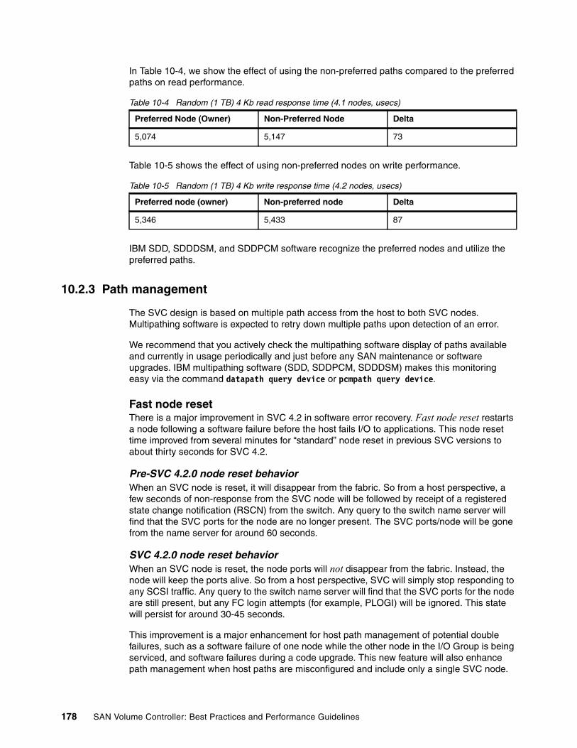
In Table 10-4, we show the effect of using the non-preferred paths compared to the preferred paths on read performance.
Table 10-4 Random (1 TB) 4 Kb read response time (4.1 nodes, usecs)
Table 10-5 shows the effect of using non-preferred nodes on write performance.
Table 10-5 Random (1 TB) 4 Kb write response time (4.2 nodes, usecs)
IBM SDD, SDDDSM, and SDDPCM software recognize the preferred nodes and utilize the preferred paths.
10.2.3 Path management
The SVC design is based on multiple path access from the host to both SVC nodes. Multipathing software is expected to retry down multiple paths upon detection of an error.
We recommend that you actively check the multipathing software display of paths available and currently in usage periodically and just before any SAN maintenance or software upgrades. IBM multipathing software (SDD, SDDPCM, SDDDSM) makes this monitoring easy via the command datapath query device or pcmpath query device.
Fast node resetThere is a major improvement in SVC 4.2 in software error recovery. Fast node reset restarts a node following a software failure before the host fails I/O to applications. This node reset time improved from several minutes for “standard” node reset in previous SVC versions to about thirty seconds for SVC 4.2.
Pre-SVC 4.2.0 node reset behaviorWhen an SVC node is reset, it will disappear from the fabric. So from a host perspective, a few seconds of non-response from the SVC node will be followed by receipt of a registered state change notification (RSCN) from the switch. Any query to the switch name server will find that the SVC ports for the node are no longer present. The SVC ports/node will be gone from the name server for around 60 seconds.
SVC 4.2.0 node reset behaviorWhen an SVC node is reset, the node ports will not disappear from the fabric. Instead, the node will keep the ports alive. So from a host perspective, SVC will simply stop responding to any SCSI traffic. Any query to the switch name server will find that the SVC ports for the node are still present, but any FC login attempts (for example, PLOGI) will be ignored. This state will persist for around 30-45 seconds.
This improvement is a major enhancement for host path management of potential double failures, such as a software failure of one node while the other node in the I/O Group is being serviced, and software failures during a code upgrade. This new feature will also enhance path management when host paths are misconfigured and include only a single SVC node.
Preferred Node (Owner) Non-Preferred Node Delta
5,074 5,147 73
Preferred node (owner) Non-preferred node Delta
5,346 5,433 87
178 SAN Volume Controller: Best Practices and Performance Guidelines

10.2.4 Dynamic reconfiguration
Many users want to dynamically reconfigure the storage connected to their hosts. The SVC gives you this capability by virtualizing the storage behind the SVC so that a host will see only the SVC VDisks presented to it. The host can then add or remove storage dynamically and reallocate using VDisk-MDisk changes.
After you decide to virtualize your storage behind an SVC, an image mode migration is used to move the existing back-end storage behind the SVC. This process is simple, seamless, and requires the host to be gracefully shut down. Then the SAN must be rezoned for SVC to be the host, the back-end storage LUNs must be moved to the SVC as a host, and the SAN rezoned for the SVC as a back-end device for the host. The host will be brought back up with the appropriate multipathing software, and the LUNs are now managed as SVC image mode VDisks. These VDisks can then be migrated to new storage or moved to striped storage anytime in the future with no host impact whatsoever.
There are times, however, when users want to change the SVC VDisk presentation to the host. The process to do this dynamically is error prone and not recommended. However, it is possible to do this by remembering several key issues.
Hosts do not dynamically reprobe storage unless prompted by some external change or by the users manually causing rediscovery. Most operating systems do not notice a change in a disk allocation automatically. There is some saved information about the device database information, such as the Windows registry or the AIX Object Data Manager (ODM) database that is utilized.
Add new VDisks or pathsNormally, adding new storage to a host and running the discovery methods (such as cfgmgr) are safe, because there is no old, leftover information that is required to be removed. Simply scan for new disks or run cfgmgr several times if necessary to see the new disks.
Removing VDisks and then later allocating new VDisks to the hostThe problem surfaces when a user removes a vdiskhostmap on the SVC during the process of removing a VDisk. After a VDisk is unmapped from the host, the device becomes unavailable and the SVC reports there is no such disk on this port. Usage of datapath query device after the removal will show a closed, offline, invalid, or dead state as shown here:
Windows host:
DEV#: 0 DEVICE NAME: Disk1 Part0 TYPE: 2145 POLICY: OPTIMIZEDSERIAL: 60050768018201BEE000000000000041============================================================================Path# Adapter/Hard Disk State Mode Select Errors 0 Scsi Port2 Bus0/Disk1 Part0 CLOSE OFFLINE 0 0 1 Scsi Port3 Bus0/Disk1 Part0 CLOSE OFFLINE 263 0
AIX host:
DEV#: 189 DEVICE NAME: vpath189 TYPE: 2145 POLICY: Optimized SERIAL: 600507680000009E68000000000007E6============================================================================Path# Adapter/Hard Disk State Mode Select Errors 0 fscsi0/hdisk1654 DEAD OFFLINE 0 0 1 fscsi0/hdisk1655 DEAD OFFLINE 2 0 2 fscsi1/hdisk1658 INVALID NORMAL 0 0 3 fscsi1/hdisk1659 INVALID NORMAL 1 0
Chapter 10. Hosts 179

The next time that a new VDisk is allocated and mapped to that host, the SCSI ID will be reused if it is allowed to set to the default value, and the host can possibly confuse the new device with the old device definition that is still left over in the device database or system memory. It is possible to get two devices that use the same identical device definitions in the device database, such as this example.
Note that both vpath189 and vpath190 have the same HDisk definitions while they actually contain different device serial numbers. The path fscsi0/hdisk1654 exists in both vpaths.
DEV#: 189 DEVICE NAME: vpath189 TYPE: 2145 POLICY: Optimized
SERIAL: 600507680000009E68000000000007E6
============================================================================
Path# Adapter/Hard Disk State Mode Select Errors
0 fscsi0/hdisk1654 CLOSE NORMAL 0 0
1 fscsi0/hdisk1655 CLOSE NORMAL 2 0
2 fscsi1/hdisk1658 CLOSE NORMAL 0 0
3 fscsi1/hdisk1659 CLOSE NORMAL 1 0
DEV#: 190 DEVICE NAME: vpath190 TYPE: 2145 POLICY: Optimized SERIAL: 600507680000009E68000000000007F4============================================================================Path# Adapter/Hard Disk State Mode Select Errors 0 fscsi0/hdisk1654 OPEN NORMAL 0 0 1 fscsi0/hdisk1655 OPEN NORMAL 6336260 0 2 fscsi1/hdisk1658 OPEN NORMAL 0 0 3 fscsi1/hdisk1659 OPEN NORMAL 6326954 0
The multipathing software (SDD) recognizes that there is a new device, because at configuration time, it issues an inquiry command and reads the mode pages. However, if the user did not remove the stale configuration data, the ODM for the old HDisks and vpaths still remains and confuses the host, because the SCSI ID as opposed to the device serial number mapping has changed. You can avoid this if you remove the HDisk and vpath information from the device configuration database (rmdev -dl vpath189, rmdev -dl hdisk1654, and so forth) prior to mapping new devices to the host and running discovery.
Removing the stale configuration and rebooting the host is the recommended procedure for reconfiguring the VDisks mapped to a host.
Another process that might cause host confusion is expanding a VDisk. The SVC will tell a host via the scsi check condition “mode parameters changed”, but not all hosts are able to automatically discover the change and might confuse LUNs or continue to use the old size.
Review the IBM System Storage SAN Volume Controller V4.2.0 - Software Installation and Configuration Guide, SC23-6628, for more details and supported hosts:
http://www-1.ibm.com/support/docview.wss?rs=591&context=STCWGAV&context=STC7HAC&context=STCWGBP&dc=DA400&q1=english&uid=ssg1S7001711&loc=en_US&cs=utf-8&lang=en
10.2.5 VDisk migration between I/O Groups
Migrating VDisks between I/O Groups is another potential issue if the old definitions of the VDisks are not removed from the configuration. Migrating VDisks between I/O Groups is not a dynamic configuration change, because each node has its own WWNN; therefore the host will see the new nodes as a different SCSI target. This process causes major configuration
180 SAN Volume Controller: Best Practices and Performance Guidelines

changes. If the stale configuration data is still known by the host, the host might continue to attempt I/O to the old I/O node targets during multipathing selection.
Example 10-3 shows the Windows SDD host display prior to I/O Group migration.
Example 10-3 Windows SDD host display prior to I/O Group migration
C:\Program Files\IBM\Subsystem Device Driver>datapath query deviceDEV#: 0 DEVICE NAME: Disk1 Part0 TYPE: 2145 POLICY: OPTIMIZEDSERIAL: 60050768018101BF28000000000000A0============================================================================Path# Adapter/Hard Disk State Mode Select Errors 0 Scsi Port2 Bus0/Disk1 Part0 OPEN NORMAL 0 0 1 Scsi Port2 Bus0/Disk1 Part0 OPEN NORMAL 1873173 0 2 Scsi Port3 Bus0/Disk1 Part0 OPEN NORMAL 0 0 3 Scsi Port3 Bus0/Disk1 Part0 OPEN NORMAL 1884768 0
DEV#: 1 DEVICE NAME: Disk2 Part0 TYPE: 2145 POLICY: OPTIMIZEDSERIAL: 60050768018101BF280000000000009F============================================================================Path# Adapter/Hard Disk State Mode Select Errors 0 Scsi Port2 Bus0/Disk2 Part0 OPEN NORMAL 0 0 1 Scsi Port2 Bus0/Disk2 Part0 OPEN NORMAL 1863138 0 2 Scsi Port3 Bus0/Disk2 Part0 OPEN NORMAL 0 0 3 Scsi Port3 Bus0/Disk2 Part0 OPEN NORMAL 1839632 0
If you just quiesce the host I/O and then migrate the VDisks to the new I/O Group, you will get closed offline paths for the old I/O Group and open normal paths to the new I/O Group. However, these devices do not work correctly, and there is no way to remove the stale paths without rebooting. Note the change in the pathing in Example 10-4 for device 0 SERIAL:S60050768018101BF28000000000000A0.
Example 10-4 Windows VDISK moved to new I/O Group dynamically showing the closed offline paths
C:\Program Files\IBM\Subsystem Device Driver>datapath query device
Total Devices : 12
DEV#: 0 DEVICE NAME: Disk1 Part0 TYPE: 2145 POLICY: OPTIMIZEDSERIAL: 60050768018101BF28000000000000A0============================================================================Path# Adapter/Hard Disk State Mode Select Errors 0 Scsi Port2 Bus0/Disk1 Part0 CLOSED OFFLINE 0 0 1 Scsi Port2 Bus0/Disk1 Part0 CLOSED OFFLINE 1873173 0 2 Scsi Port3 Bus0/Disk1 Part0 CLOSED OFFLINE 0 0 3 Scsi Port3 Bus0/Disk1 Part0 CLOSED OFFLINE 1884768 0 4 Scsi Port2 Bus0/Disk1 Part0 OPEN NORMAL 0 0 5 Scsi Port2 Bus0/Disk1 Part0 OPEN NORMAL 45 0 6 Scsi Port3 Bus0/Disk1 Part0 OPEN NORMAL 0 0 7 Scsi Port3 Bus0/Disk1 Part0 OPEN NORMAL 54 0
DEV#: 1 DEVICE NAME: Disk2 Part0 TYPE: 2145 POLICY: OPTIMIZEDSERIAL: 60050768018101BF280000000000009F============================================================================Path# Adapter/Hard Disk State Mode Select Errors 0 Scsi Port2 Bus0/Disk2 Part0 OPEN NORMAL 0 0
Chapter 10. Hosts 181
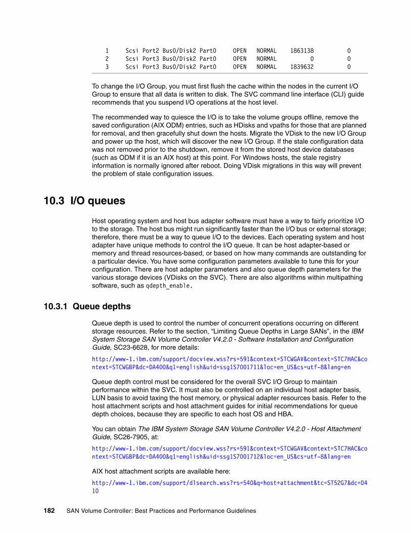
1 Scsi Port2 Bus0/Disk2 Part0 OPEN NORMAL 1863138 0 2 Scsi Port3 Bus0/Disk2 Part0 OPEN NORMAL 0 0 3 Scsi Port3 Bus0/Disk2 Part0 OPEN NORMAL 1839632 0
To change the I/O Group, you must first flush the cache within the nodes in the current I/O Group to ensure that all data is written to disk. The SVC command line interface (CLI) guide recommends that you suspend I/O operations at the host level.
The recommended way to quiesce the I/O is to take the volume groups offline, remove the saved configuration (AIX ODM) entries, such as HDisks and vpaths for those that are planned for removal, and then gracefully shut down the hosts. Migrate the VDisk to the new I/O Group and power up the host, which will discover the new I/O Group. If the stale configuration data was not removed prior to the shutdown, remove it from the stored host device databases (such as ODM if it is an AIX host) at this point. For Windows hosts, the stale registry information is normally ignored after reboot. Doing VDisk migrations in this way will prevent the problem of stale configuration issues.
10.3 I/O queues
Host operating system and host bus adapter software must have a way to fairly prioritize I/O to the storage. The host bus might run significantly faster than the I/O bus or external storage; therefore, there must be a way to queue I/O to the devices. Each operating system and host adapter have unique methods to control the I/O queue. It can be host adapter-based or memory and thread resources-based, or based on how many commands are outstanding for a particular device. You have some configuration parameters available to tune this for your configuration. There are host adapter parameters and also queue depth parameters for the various storage devices (VDisks on the SVC). There are also algorithms within multipathing software, such as qdepth_enable.
10.3.1 Queue depths
Queue depth is used to control the number of concurrent operations occurring on different storage resources. Refer to the section, “Limiting Queue Depths in Large SANs”, in the IBM System Storage SAN Volume Controller V4.2.0 - Software Installation and Configuration Guide, SC23-6628, for more details:
http://www-1.ibm.com/support/docview.wss?rs=591&context=STCWGAV&context=STC7HAC&context=STCWGBP&dc=DA400&q1=english&uid=ssg1S7001711&loc=en_US&cs=utf-8&lang=en
Queue depth control must be considered for the overall SVC I/O Group to maintain performance within the SVC. It must also be controlled on an individual host adapter basis, LUN basis to avoid taxing the host memory, or physical adapter resources basis. Refer to the host attachment scripts and host attachment guides for initial recommendations for queue depth choices, because they are specific to each host OS and HBA.
You can obtain The IBM System Storage SAN Volume Controller V4.2.0 - Host Attachment Guide, SC26-7905, at:
http://www-1.ibm.com/support/docview.wss?rs=591&context=STCWGAV&context=STC7HAC&context=STCWGBP&dc=DA400&q1=english&uid=ssg1S7001712&loc=en_US&cs=utf-8&lang=en
AIX host attachment scripts are available here:
http://www-1.ibm.com/support/dlsearch.wss?rs=540&q=host+attachment&tc=ST52G7&dc=D410
182 SAN Volume Controller: Best Practices and Performance Guidelines

Queue depth control within the host is accomplished via limits placed by the adapter resources for handling I/Os and by setting a queue depth maximum per LUN. Multipathing software also controls queue depth using different algorithms. SDD recently made an algorithm change in this area to limit queue depth individually by LUN as opposed to an overall system queue depth limitation.
The host I/O will be converted to MDisk I/O as needed. The SVC submits I/O to the back-end (MDisk) storage as any host normally does. The host allows user control of the queue depth that is maintained on a disk. SVC does this internally for MDisk I/O without any user intervention. After SVC has submitted I/Os and has “Q” I/Os per second (IOPS) outstanding for a single MDisk (that is, it is waiting for Q I/Os to complete), it will not submit any more I/O until some I/O completes. That is, any new I/O requests for that MDisk will be queued inside SVC.
The following graphs in Figure 10-1 indicate the effect on host VDisk queue depth for a simple configuration of 16 VDisks and one host.
Figure 10-1 IOPS compared to queue depth for 16 disk tests using a single host
Figure 10-2 on page 184 shows another example of queue depth sensitivity for 16 disks on a single host.
Chapter 10. Hosts 183

Figure 10-2 MB/s compared to queue depth for 16 disk tests on a single host
10.4 Multipath software
The SVC requires the use of multipathing software on hosts that are connected. The latest recommended levels for each host operating system and multipath software package are documented in the SVC Web site:
http://www-1.ibm.com/support/docview.wss?rs=591&uid=ssg1S1003090#_Multi_Host
Note that the prior levels of host software packages that were recommended are also tested for SVC 4.2 and allow for flexibility in maintaining the host software levels with respect to the SVC software version. In other words, it is possible to upgrade the SVC before upgrading the host software levels or after upgrading the software levels, depending on your maintenance schedule.
10.5 Host clustering and reserves
To prevent hosts from sharing storage inadvertently, it is prudent to establish a storage reservation mechanism. The mechanisms for restricting access to SVC VDisks utilize the Small Computer Systems Interface-3 (SCSI-3) persistent reserve commands or the SCSI-2 legacy reserve and release commands.
There are several methods that the host software uses for implementing host clusters. They require sharing the VDisks on the SVC between hosts. In order to share storage between hosts, some type of control is maintained over accessing the VDisks. Some clustering software uses software locking methods. Other methods of control can be chosen by the clustering software or by the device drivers to utilize the SCSI architecture reserve/release mechanisms. The multipathing software can change the type of reserve used from a legacy reserve to persistent reserve, or remove the reserve.
184 SAN Volume Controller: Best Practices and Performance Guidelines

Persistent reserve refers to a set of Small Computer Systems Interface-3 (SCSI-3) standard commands and command options that provide SCSI initiators with the ability to establish, preempt, query, and reset a reservation policy with a specified target device. The functionality provided by the persistent reserve commands is a superset of the legacy reserve/release commands. The persistent reserve commands are incompatible with the legacy reserve/release mechanism, and target devices can only support reservations from either the legacy mechanism or the new mechanism. Attempting to mix persistent reserve commands with legacy reserve/release commands will result in the target device returning a reservation conflict error.
Legacy reserve and release mechanisms (SCSI-2) reserved the entire LUN (VDisk) for exclusive use down a single path, which prevents access from any other host or even access from the same host utilizing a different host adapter.
The persistent reserve design establishes a method and interface through a reserve policy attribute for SCSI disks, which specifies the type of reservation (if any) that the OS device driver will establish before accessing data on the disk.
Four possible values are supported for the reserve policy:
� No_reserve: No reservations are used on the disk.
� Single_path: Legacy reserve/release commands are used on the disk.
� PR_exclusive: Persistent reservation is used to establish exclusive host access to the disk.
� PR_shared: Persistent reservation is used to establish shared host access to the disk.
When a device is opened (for example, when the AIX varyonvg command opens the underlying HDisks), the device driver will check the ODM for a reserve_policy and a PR_key_value and open the device appropriately. For persistent reserve, it is necessary that each host attached to the shared disk use a unique registration key value.
Clearing reservesIt is possible to accidently leave a reserve on the SVC VDisk or even the SVC MDisk during migration into the SVC or when reusing disks for another purpose. There are several tools available from the hosts to clear these reserves. The easiest tools to use are the commands lquerypr (AIX SDD host) and pcmquerypr (AIX SDDPCM host). There is also a Windows SDD/SDDDSM tool, which is menu driven.
The Windows Persistent Reserve Tool is called PRTool.exe and is installed automatically when SDD or SDDDSM is installed.
C:\Program Files\IBM\Subsystem Device Driver>PRTool.exe
It is possible to clear SVC VDisk reserves by removing all the host-VDisk mappings when SVC code is at 4.1.0 or higher.
Here is an example of how to determine if there is a reserve on a device using the AIX SDD lquerypr command on a reserved HDisk:
[root@ktazp5033]/reserve-checker-> lquerypr -vVh /dev/hdisk5
connection type: fscsi0
open dev: /dev/hdisk5
Attempt to read reservation key...
Attempt to read registration keys...
Chapter 10. Hosts 185
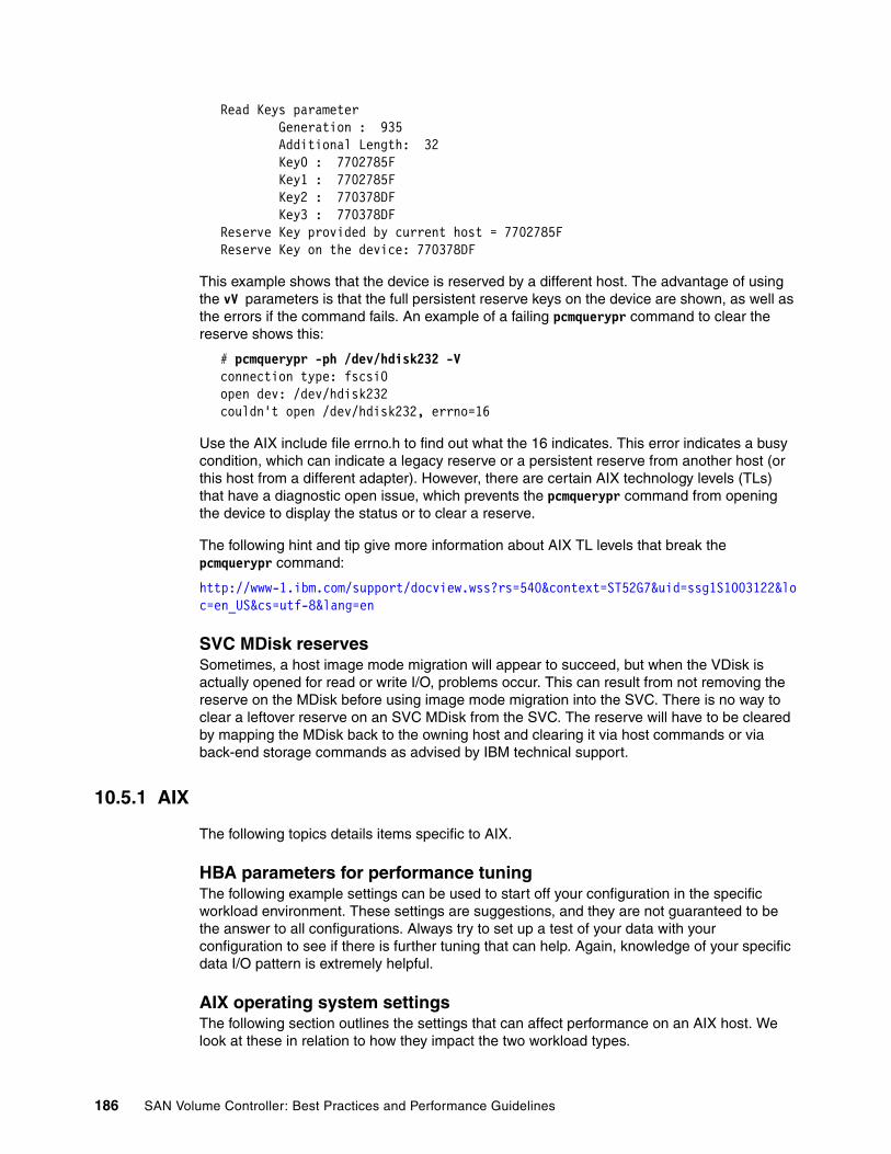
Read Keys parameter Generation : 935 Additional Length: 32 Key0 : 7702785F Key1 : 7702785F Key2 : 770378DF Key3 : 770378DF Reserve Key provided by current host = 7702785F Reserve Key on the device: 770378DF
This example shows that the device is reserved by a different host. The advantage of using the vV parameters is that the full persistent reserve keys on the device are shown, as well as the errors if the command fails. An example of a failing pcmquerypr command to clear the reserve shows this:
# pcmquerypr -ph /dev/hdisk232 -V connection type: fscsi0 open dev: /dev/hdisk232 couldn't open /dev/hdisk232, errno=16
Use the AIX include file errno.h to find out what the 16 indicates. This error indicates a busy condition, which can indicate a legacy reserve or a persistent reserve from another host (or this host from a different adapter). However, there are certain AIX technology levels (TLs) that have a diagnostic open issue, which prevents the pcmquerypr command from opening the device to display the status or to clear a reserve.
The following hint and tip give more information about AIX TL levels that break the pcmquerypr command:
http://www-1.ibm.com/support/docview.wss?rs=540&context=ST52G7&uid=ssg1S1003122&loc=en_US&cs=utf-8&lang=en
SVC MDisk reservesSometimes, a host image mode migration will appear to succeed, but when the VDisk is actually opened for read or write I/O, problems occur. This can result from not removing the reserve on the MDisk before using image mode migration into the SVC. There is no way to clear a leftover reserve on an SVC MDisk from the SVC. The reserve will have to be cleared by mapping the MDisk back to the owning host and clearing it via host commands or via back-end storage commands as advised by IBM technical support.
10.5.1 AIX
The following topics details items specific to AIX.
HBA parameters for performance tuningThe following example settings can be used to start off your configuration in the specific workload environment. These settings are suggestions, and they are not guaranteed to be the answer to all configurations. Always try to set up a test of your data with your configuration to see if there is further tuning that can help. Again, knowledge of your specific data I/O pattern is extremely helpful.
AIX operating system settingsThe following section outlines the settings that can affect performance on an AIX host. We look at these in relation to how they impact the two workload types.
186 SAN Volume Controller: Best Practices and Performance Guidelines

Transaction-based settingsThe following host attachment script will set the default values of attributes for the SVC HDisks:
devices.fcp.disk.IBM.rte or devices.fcp.disk.IBM.mpio.rte
These values can be modified but are a very good place to start. There are additionally some HBA parameters that are useful to set for higher performance or large numbers of HDisk configurations.
All attribute values that are changeable can be changed using the chdev command for AIX.
AIX settings, which can directly affect transaction performance, are the queue_depth HDisk attribute, and num_cmd_elem in the HBA attributes.
queue_depthFor the logical drive known as the HDisk in AIX, the setting is the attribute queue_depth:
# chdev -l hdiskX -a queue_depth=Y -P
In this example, “X” is the HDisk number, and “Y” is the value to which you are setting X for queue_depth.
For a high transaction workload of small random transfers, try queue_depth of 25 or more, but for large sequential workloads, performance is better with shallow queue depths, such as 4.
num_cmd_elemFor the HBA settings, the attribute num_cmd_elem for the fcs device represents the number of commands that can be queued to the adapter.
chdev -l fcsX -a num_cmd_elem=1024 -P
The default value is 200, and the maximum value is:LP9000 adapters: 2048 LP10000 adapters: 2048LP11000 adapters: 2048LP7000 adapters: 1024
AIX settings which can directly affect throughput performance with large I/O block size are the lg_term_dma and max_xfer_size parameters for the fcs device.
lg_term_dmaThis AIX Fibre Channel adapter attribute controls the direct memory access (DMA) memory resource that an adapter driver can use. The default value of lg_term_dma is 0x200000, and the maximum value is 0x8000000. A recommended change is to increase the value of lg_term_dma to 0x400000. If you still experience poor I/O performance after changing the value to 0x400000, you can increase the value of this attribute again. If you have a dual-port Fibre Channel adapter, the maximum value of the lg_term_dma attribute is divided between the two adapter ports. Therefore, never increase lg_term_dma to the maximum value for a
Best practice: For high transactions on AIX or large numbers of HDisks on the fcs adapter, we recommend that you increase num_cmd_elem to 1024 for the fcs devices being used.
Chapter 10. Hosts 187

dual-port Fibre Channel adapter, because this will cause the configuration of the second adapter port to fail.
max_xfer_sizeThis AIX Fibre Channel adapter attribute controls the maximum transfer size of the Fibre Channel adapter. Its default value is 100000, and the maximum value is 1000000. You can increase this attribute to improve performance. You can change this attribute only with AIX 5.2.0 or later.
Note that setting the max_xfer_size affects the size of a memory area used for data transfer by the adapter. With the default value of max_xfer_size=0x100000, the area is 16 MB in size, and for other allowable values of max_xfer_size, the memory area is 128 MB in size.
Throughput-based settingsIn the throughput-based environment, you might want to decrease the queue depth setting to a smaller value than the default from the host attach. In a mixed application environment, you do not want to lower the “num_cmd_elem” setting, because other logical drives might need this higher value to perform. In a pure high throughput workload, this value will have no effect.
We recommend that you test your host with the default settings first and then make these possible tuning changes to the host parameters to verify if these suggested changes actually enhance performance for your specific host configuration and workload.
Configuring for fast fail and dynamic tracking For host systems that run an AIX 5.2 or later operating system, you can achieve the best results by using the fast fail and dynamic tracking attributes. Before configuring your host system to use these attributes, ensure that the host is running the AIX operating system Version 5.2 or later. Perform the following steps to configure your host system to use the fast fail and dynamic tracking attributes:
1. Issue the following command to set the Fibre Channel SCSI I/O Controller Protocol Device event error recovery policy to fast_fail for each Fibre Channel adapter:
chdev -l fscsi0 -a fc_err_recov=fast_fail
The previous example command was for adapter fscsi0.
2. Issue the following command to enable dynamic tracking for each Fibre Channel device:
chdev -l fscsi0 -a dyntrk=yes
The previous example command was for adapter fscsi0.
MultipathingWhen the AIX operating system was first developed, multipathing was not embedded within the device drivers. Therefore, each path to an SVC VDisk was represented by an AIX HDisk. The SVC host attachment script devices.fcp.disk.ibm.rte sets up the predefined attributes within the AIX database for SVC disks, and these attributes have changed with each iteration of host attachment and AIX technology levels. Both SDD and Veritas DMP utilize the HDisks for multipathing control. The host attachment is also used for other IBM storage devices. The Host Attachment allows AIX device driver configuration methods to properly identify and configure SVC (2145), DS6000 (1750), and DS8000 (2107) LUNs:
Best practice: The recommended start values for high throughput sequential I/O environments are lg_term_dma = 0x400000 or 0x800000 (depending on the adapter type) and max_xfr_size = 0x200000.
188 SAN Volume Controller: Best Practices and Performance Guidelines

http://www-1.ibm.com/support/docview.wss?rs=540&context=ST52G7&dc=D410&q1=host+attachment&uid=ssg1S4000106&loc=en_US&cs=utf-8&lang=en
SDDIBM Subsystem Device Driver (SDD) multipathing software has been designed and updated consistently over the last decade and is a very mature multipathing technology. The SDD software also supports many other IBM storage types directly connected to AIX, such as the 2107. SDD algorithms for handling multipathing have also evolved. There are throttling mechanisms within SDD that controlled overall I/O bandwidth in SDD releases 1.6.1.0 and earlier. This throttling mechanism has evolved to be single vpath specific and is called qdepth_enable in later releases.
SDD utilizes persistent reserve functions, placing a persistent reserve on the device in place of the legacy reserve when the volume group is varyon. However, if HACMP is installed, HACMP controls the persistent reserve usage depending on the type of varyon used. Also, the enhanced concurrent volume groups (VGs) have no reserves: varyonvg -c for enhanced concurrent and varyonvg for regular VGs that utilize the persistent reserve.
Datapath commands are a very powerful method for managing the SVC storage and pathing. The output shows the LUN serial number of the SVC VDisk and which vpath and HDisk represent that SVC LUN. Datapath commands can also change the multipath selection algorithm. The default is load balance, but this is programmable. The recommended best practice when using SDD is also load balance using four paths. The datapath query device output will show a somewhat balanced number of selects on each preferred path to the SVC:
DEV#: 12 DEVICE NAME: vpath12 TYPE: 2145 POLICY: Optimized SERIAL: 60050768018B810A88000000000000E0====================================================================Path# Adapter/Hard Disk State Mode Select Errors 0 fscsi0/hdisk55 OPEN NORMAL 1390209 0 1 fscsi0/hdisk65 OPEN NORMAL 0 0 2 fscsi0/hdisk75 OPEN NORMAL 1391852 0 3 fscsi0/hdisk85 OPEN NORMAL 0 0
We recommend that you verify the selects during normal operation are occurring on the preferred paths (use datapath query device -l). Also, verify that you have the correct connectivity.
SDDPCMAs Fibre Channel technologies matured, AIX was enhanced by adding native multipathing support called Multipath I/O (MPIO). This structure allows a manufacturer of storage to create software plug-ins for their specific storage. The IBM SVC version of this plug-in is called SDDPCM. This requires a different host attachment script called devices.fcp.disk.ibm.mpio.rte:
http://www-1.ibm.com/support/docview.wss?rs=540&context=ST52G7&dc=D410&q1=host+attachment&uid=ssg1S4000203&loc=en_US&cs=utf-8&lang=en
SDDPCM and AIX MPIO have been continually improved since their release. We recommend that you are at the latest release levels of this software.
The preferred path indicator for SDDPCM will not display until after the device has been opened for the first time. This is different than SDD, which will display the preferred path immediately after being configured.
SDDPCM features four types of reserve policies:
Chapter 10. Hosts 189

� No_reserve policy� Exclusive host access single path policy� Persistent reserve exclusive host policy� Persistent reserve shared host access policy
The usage of the persistent reserve now depends on the HDisk attribute: reserve_policy. Change this policy to match your storage security requirements.
There are three path selection algorithms:
� Failover� Round robin� Load balancing
The latest SDDPCM code of 2.1.3.0 and later has improvements in failed path reclamation by health checker, a failback error recovery algorithm, Fibre Channel dynamic device tracking, and support for SAN boot device on MPIO-supported storage devices.
10.5.2 SDD compared to SDDPCM
There are several reasons for choosing SDDPCM over SDD. SAN boot is much improved with native mpio-sddpcm software. Multiple VIOSs are supported. Certain applications, such as Oracle® ASM, will not work with SDD.
Another thing that might be worthwhile noting is that with SDD, all paths can go to dead, which will improve HACMP and Logical Volume Manager (LVM) mirroring failovers. With SDDPCM, one path will always remain open even if the LUN is dead. This design causes longer failovers.
With SDDPCM utilizing HACMP, enhanced concurrent volume groups require the no reserve policy for both concurrent and non-concurrent resource groups. Therefore, HACMP uses a software locking mechanism instead of implementing persistent reserves. HACMP used with SDD does utilize persistent reserves based on what type of varyonvg was executed.
SDDPCM pathingSDDPCM pcmpath commands are the best way to understand configuration information about the SVC storage allocation. The following example shows how much can be determined from this command about the connections to the SVC from this host.
pcmpath query device
DEV#: 0 DEVICE NAME: hdisk0 TYPE: 2145 ALGORITHM: Load Balance SERIAL: 6005076801808101400000000000037B ======================================================================Path# Adapter/Path Name State Mode Select Errors 0 fscsi0/path0 OPEN NORMAL 155009 0 1 fscsi1/path1 OPEN NORMAL 155156 0
In this example, both paths are being used for the SVC connections. This is not the normal select counts for a properly mapped SVC, nor is this an adequate number of paths. Use the “-l” option on pcmpath query device to check whether these are both preferred paths. If they are, one SVC node must be missing from the host view.
Using the -l option shows an asterisk on both paths, indicating a single node is visible to the host (and is the non-preferred node for this VDisk).
0* fscsi0/path0 OPEN NORMAL 9795 0 1* fscsi1/path1 OPEN NORMAL 9558 0
190 SAN Volume Controller: Best Practices and Performance Guidelines

This indicates a problem that needs to be corrected. If zoning in the switch is correct, perhaps this host was rebooted while one SVC node was missing from the fabric.
VeritasVeritas DMP multipathing is also supported for the SVC. This requires certain AIX APARS, and the Veritas Array Support Library. It also requires a certain version of the host attachment script devices.fcp.disk.ibm.rte to recognize the 2,145 devices as HDisks rather than MPIO HDisks. In addition to the normal ODM databases that contain HDisk attributes, there are several Veritas filesets that contain configuration data:
� /dev/vx/dmp
� /dev/vx/rdmp
� /etc/vxX.info
Storage reconfiguration of VDisks presented to an AIX host will require cleanup of the AIX HDisks and these Veritas filesets.
10.5.3 Virtual I/O server
Virtual SCSI is based on a client and server relationship. The Virtual I/O Server (VIOS) owns the physical resources and acts as server, or target, device. Physical adapters with attached disks (VDisks on the SVC, in our case) on the Virtual I/O Server partition can be shared by one or more partitions. These partitions contain a virtual SCSI client adapter that sees these virtual devices as standard SCSI compliant devices and LUNs.
There are two types of VDisks that you can create on a VIOS: physical volume (PV) VSCSI HDisks and logical volume (LV) VSCSI HDisks.
PV VSCSI HDisks are entire LUNs from the VIOS point of view, and if you are concerned about failure of a VIOS and have configured redundant VIOSs for that reason, you must use PV VSCSI HDisks. So, PV VSCSI HDisks are entire LUNs that are VDisks from the virtual I/O client (VIOC) point of view. An LV VCSI HDisk cannot be served up from multiple VIOSs. LV VSCSI HDisks reside in LVM VGs on the VIOS and cannot span PVs in that VG, nor be striped LVs. Due to these restrictions, we recommend using PV VSCSI HDisks.
Multipath support for SVC attachment to Virtual I/O Server is provided by either SDD or MPIO with SDDPCM. Where Virtual I/O Server SAN Boot or dual Virtual I/O Server configurations are required, only MPIO with SDDPCM is supported. We recommend using MPIO with SDDPCM due to this restriction with the latest SVC-supported levels as shown by:
http://www-1.ibm.com/support/docview.wss?rs=591&uid=ssg1S1003090#_Virtual_IO_Server
Details of the Virtual I/O Server-supported environments are at:
http://www14.software.ibm.com/webapp/set2/sas/f/vios/home.html
There are many questions answered on the following Web site for usage of the VIOS:
http://www14.software.ibm.com/webapp/set2/sas/f/vios/documentation/faq.html
One common question is how to migrate data into a VIO environment or how to reconfigure storage on a VIOS. This question is addressed in the previous link.
Many clients ask, “Can SCSI LUNs be moved between the physical and virtual environment “as is”? That is, given a physical SCSI device (LUN) with user data on it that resides in a SAN environment, can this device be allocated to a VIOS and then provisioned to a client partition and used by the client “as is”?”
Chapter 10. Hosts 191

The answer is no, this function is not supported at this time. The device cannot be used “as is”. Virtual SCSI devices are new devices when created, and the data must be put onto them after creation. This typically requires some type of backup of the data in the physical SAN environment with a restoration of the data onto the VDisk.
Why do we have this limitationThe VIOS uses several methods to uniquely identify a disk for use as a virtual SCSI disk; they are:
� Unique device identifier (UDID) � IEEE volume identifier � Physical volume identifier (PVID)
Each of these methods can result in different data formats on the disk. The preferred disk identification method for VDisks is the use of UDIDs.
MPIO uses the UDID methodMost non-MPIO disk storage multi-pathing software products use the PVID method instead of the UDID method. Because of the different data format associated with the PVID method, clients with non-MPIO environments need to be aware that certain future actions performed in the VIOS logical partition (LPAR) can require data migration, that is, some type of backup and restore of the attached disks. These actions can include, but are not limited to:
� Conversion from a non-MPIO environment to MPIO
� Conversion from the PVID to the UDID method of disk identification
� Removal and rediscovery of the Disk Storage ODM entries
� Updating non-MPIO multipathing software under certain circumstances
� Possible future enhancements to VIO
Due in part to the differences in disk format that we just described, VIO is currently supported for new disk installations only.
AIX, VIO, and SDD development are working on changes to make this easier in the future. One enhancement is to use the UDID or IEEE method of disk identification. If you use the UDID method, it might be possible to contact IBM technical support to get a method of migrating that might not require restoration.
A quick and simple method to determine if a backup and restore is necessary is to run the command lquerypv -h /dev/hdisk## 80 10 to read the PVID off the disk. If the output is different on both the VIOS and VIOC, you must use backup and restore.
How to back up the VIO configurationThis details how to back up the VIO configuration:
1. Save off the volume group information from the VIOC (PVIDs and VG names).
2. Save off the disk mapping, PVID, and LUN ID information from ALL VIOSs. This is mapping VIOS HDisk (typically a HDisk) to the VIOC HDisk and needs to have at least the PVIDs information saved.
3. Save off the physical LUN to host LUN ID information on the storage subsystem for when we reconfigure the HDisk (typically).
After all the pertinent mapping data has been collected and saved, it is possible to back up and reconfigure your storage and then restore using the AIX commands:
� Back up the VG data on the VIOC.
192 SAN Volume Controller: Best Practices and Performance Guidelines

� For rootvg, the supported method is a mksysb and an install, or savevg and restvg for non-rootvg.
10.5.4 Windows
There are two options of multipathing drivers released for Windows 2003 Server hosts. Windows 2003 Server device driver development has concentrated on the storport.sys driver. This driver has significant interoperability differences from the older scsiport driver set. Additionally, Windows has released a native multipathing I/O option with a storage specific plug-in. SDDDSM was designed to support these newer methods of interfacing with Windows 2003 Server. In order to release new enhancements more quickly, the newer hardware architectures (64-bit EMT and so forth) are only tested on the SDDDSM code stream; therefore, only SDDDSM packages are available.
The older version of SDD multipathing driver works with the scsiport drivers. This version is required for Windows Server® 2000 servers, because storport.sys is not available. The SDD software is also available for Windows 2003 Server servers when the scsiport hba drivers are used.
Clustering and reservesWindows SDD or SDDDSM utilizes the persistent reserve functions to implement Windows Clustering. A stand-alone Windows host will not utilize reserves.
Review this Microsoft® article about clustering to understand how a cluster works:
http://support.microsoft.com/kb/309186/
When SDD or SDDDSM is installed, the reserve and release functions described in this article are translated into proper persistent reserve and release equivalents to allow load balancing and multipathing from each host.
SDD compared to SDDDSMThe main requirement for choosing SDD over SDDSM is to ensure the matching host bus adapter driver type is also loaded on the system. Choose the storport driver for sdddsm and the scsiport versions for SDD. From an error isolation perspective, the tracing available and collected by sddgetdata is easier to follow with the SDD software and is a more mature release. Future enhancements will concentrate on SDDDSM within the windows MPIO framework.
Tunable parametersWith Windows operating systems, the queue depth settings are the responsibility of the host adapters and configured through the BIOS setting. This varies from vendor to vendor. Refer to your manufacturer’s instructions about how to configure your specific cards and the IBM System Storage SAN Volume Controller Host Attachment User’s Guide Version 4.2.0, SC26-7905:
http://www-1.ibm.com/support/docview.wss?rs=591&context=STCWGAV&context=STC7HAC&context=STCWGBP&dc=DA400&q1=english&uid=ssg1S7001712&loc=en_US&cs=utf-8&lang=en
Queue depth is also controlled by the Windows application program. The application program has control of how many I/O commands it will allow to be outstanding before waiting for completion.
Chapter 10. Hosts 193

For IBM FAStT FC2-133 (and QLogic-based HBAs), the queue depth is known as execution throttle, which can be set with either the QLogic SANSurfer tool or in the BIOS of the QLogic-based HBA by pressing CTL+Q during the startup process.
10.5.5 Linux
IBM has decided to transition SVC multipathing support from IBM SDD to Linux native DM-MPIO multipathing. Refer to the V4.2.0 - Recommended Software Levels for SAN Volume Controller for which versions of each Linux kernel require SDD or DM-MPIO support:
http://www-1.ibm.com/support/docview.wss?rs=591&uid=ssg1S1003090#_Supported_Host_operating_system_Lev
If your kernel is not listed for support, contact your IBM marketing representative to request a Request for Price Quotation (RPQ) for your specific configuration.
Linux Clustering is not supported, and Linux OS does not use the legacy reserve function. Therefore, there are no persistent reserves used in Linux. Contact IBM marketing for RPQ support if you need Linux Clustering in your specific environment.
SDD compared to DM-MPIOFor reference on the multipathing choices for Linux operating systems, SDD development has provided the white paper, Considerations and Comparisons between IBM SDD for Linux and DM-MPIO, which is available at:
http://www-1.ibm.com/support/docview.wss?rs=540&context=ST52G7&q1=linux&uid=ssg1S7001664&loc=en_US&cs=utf-8&lang=en
Tunable parametersLinux performance is influenced by HBA parameter settings and queue depth. Queue depth for Linux servers can be determined by using the formula specified in the IBM System Storage SAN Volume Controller: Software Installation and Configuration Guide, SC23-6628:
http://www-1.ibm.com/support/docview.wss?uid=ssg1S7001711
Refer to the settings for each specific HBA type and general Linux OS tunable parameters in the IBM System Storage SAN Volume Controller V4.2.0 - Host Attachment Guide, SC26-7905:
http://www-1.ibm.com/support/docview.wss?rs=591&context=STCWGAV&context=STC7HAC&context=STCWGBP&dc=DA400&q1=english&uid=ssg1S7001712&loc=en_US&cs=utf-8&lang=en
In addition to the I/O and OS parameters, Linux also has tunable file system parameters.
The command tune2fs can be used to increase file system performance based on your specific configuration. The journal mode and size can be changed. Also, the directories can be indexed. Refer to the following open source document for details:
http://swik.net/how-to-increase-ext3-and-reiserfs-filesystems-performance
10.5.6 Solaris
There are several options for multipathing support on Solaris™ hosts. You can choose between IBM SDD, Symantec/VERITAS Volume Manager, or you can use Solaris MPxIO depending on the OS levels in the latest SVC software level matrix.
194 SAN Volume Controller: Best Practices and Performance Guidelines

SAN startup support and clustering support are available for Symantec/VERITAS Volume Manager, and SAN boot support is also available for MPxIO.
Solaris MPxIOReleases of SVC code prior to 4.2 did not support load balancing of the MPxIO software.
Configure your SVC host object with the type attribute set to tpgs if you want to run MPxIO on your Sun™ SPARC host. For example:
svctask mkhost -name new_name_arg -hbawwpn wwpn_list -type tpgs
Where -type specifies the type of host. Valid entries are hpux, tpgs, or generic. The tpgs option enables extra target port unit attentions. The default is generic.
Symantec/VERITAS Volume ManagerWhen managing IBM SVC storage in Symantec’s volume manager products, you must install an array support library (ASL) on the host so that the volume manager is aware of the storage subsystem properties (active/active, active/passive). If the appropriate ASL is not installed, the volume manager has not claimed the LUNs. Usage of the ASL is required to enable the special failover/failback multipathing that SVC requires for error recovery.
Use the following commands to determine the basic configuration of a Symantec/Veritas server:
pkginfo –l (lists all installed packages)showrev -p |grep vxvm (to obtain version of volume manager)vxddladm listsupport (to see what ASLs are configured)vxdisk list vxdmpadm listctrl all (shows all attached subsystems, and provides a type where possible)vxdmpadm getsubpaths ctlr=cX (lists paths by controller)vxdmpadm getsubpaths dmpnodename=cxtxdxs2’ (lists paths by lun)
The following commands will determine if the SVC is properly connected and show at a glance which ASL library is used (native DMP ASL or SDD ASL).
Here is an example of what you see when Symantec volume manager is correctly seeing our SVC, using the SDD passthrough mode ASL:
# vxdmpadm list enclosure allENCLR_NAME ENCLR_TYPE ENCLR_SNO STATUS============================================================OTHER_DISKS OTHER_DISKS OTHER_DISKS CONNECTEDVPATH_SANVC0 VPATH_SANVC 0200628002faXX00 CONNECTED
Here is an example of what we see when SVC is configured using native DMP ASL:
# vxdmpadm listenclosure allENCLR_NAME ENCLR_TYPE ENCLR_SNO STATUS============================================================OTHER_DISKS OTHER_DSKSI OTHER_DISKS CONNECTEDSAN_VC0 SAN_VC 0200628002faXX00 CONNECTED
ASL specifics for SVCFor SVC, ASLs have been developed using both DMP multipathing or SDD passthrough multipathing.
Chapter 10. Hosts 195
For SDD passthrough:
http://support.veritas.com/docs/281321
# pkginfo -l VRTSsanvcPKG=VRTSsanvcBASEDIR=/etc/vxNAME=Array Support Library for IBM SAN.VC with SDD.PRODNAME=VERITAS ASL for IBM SAN.VC with SDD.
For native DMP:
http://support.veritas.com/docs/276913pkginfo -l VRTSsanvcPKGINST: VRTSsanvc NAME: Array Support Librarry for IBM SAN.VC in NATIVE DMP mode
To check the installed Symantec/VERITAS version:
showrev -p |grep vxvm
To check what IBM ASLs are configured into the volume manager:
vxddladm listsupport |grep -i ibm
Following install of a new ASL using pkgadd, you need to either reboot or issue vxdctl enable. To list what ASLs are active, run vxddladm listsupport.
How to troubleshoot configuration issuesHere is an example of what things look like if the appropriate ASL is not installed or the system has not enabled the ASL. The key is the enclosure type OTHER_DISKS.
vxdmpadm listctlr allCTLR-NAME ENCLR-TYPE STATE ENCLR-NAME=====================================================c0 OTHER_DISKS ENABLED OTHER_DISKSc2 OTHER_DISKS ENABLED OTHER_DISKSc3 OTHER_DISKS ENABLED OTHER_DISKS
vxdmpadm listenclosure allENCLR_NAME ENCLR_TYPE ENCLR_SNO STATUS============================================================OTHER_DISKS OTHER_DISKS OTHER_DISKS CONNECTEDDisk Disk DISKS DISCONNECTED
10.5.7 VMWare
Review the V4.2.0 - Recommended Software Levels for SAN Volume Controller Web site for the various ESX levels that are supported:
http://www-1.ibm.com/support/docview.wss?rs=591&uid=ssg1S1003090#_VMWare
Support for specific configurations for VMWare 3.01 is provided by special engineering request only. Contact your IBM marketing representative for details and the submission of an RPQ. The necessary patches and procedure to apply them will be supplied once the specific configuration is reviewed and approved.
196 SAN Volume Controller: Best Practices and Performance Guidelines
10.6 Mirroring considerations
As you plan how to fully utilize the various options to back up your data via mirroring functions, consider how to keep a consistent set of data for your application. This implies some level of control by the application or host scripts to start and stop mirroring with both host-based mirroring and back-end storage mirroring features. It also implies a group of disks that must be kept consistent with respect to each other.
Host applications have a certain granularity to their storage writes. The data has a consistent view to the host application only at certain times. This level of granularity is at the file system level as opposed to the SCSI read/write level. The SVC guarantees consistency at the SCSI read/write level when its features of mirroring are in use. However, a host file system write might require multiple SCSI writes to accomplish this. Therefore, without some method of controlling when the mirror stops, the resulting mirror can be missing a portion of a write and look corrupted. Normally, a database application has methods to recover the mirrored data and to back up to a consistent view. This is applicable in case of a disaster that breaks the mirror. However, we recommend that you have a normal procedure of stopping at a consistent view for each mirror to be able to easily start up the backup copy for non-disaster scenarios.
10.6.1 Host-based mirroring
Host-based mirroring is a fully redundant method of mirroring using two mirrored copies of the data. Mirroring is done by the host software. If this method of mirroring is used, we recommend that each copy is placed on a separate SVC cluster.
10.7 Monitoring
A consistent set of monitoring tools is available when IBM SDD, SDDDSM, and SDDPCM are used for the multipathing software on the various OS environments. Examples earlier in this chapter showed how the datapath query device and datapath query adapter commands can be used for path monitoring.
Path performance can also be monitored via datapath commands:
datapath query devstats. (or pcmpath query devstats)
This command shows performance information for a single device, all devices, or a range of devices. Example 10-5 shows the output of datapath query devstats for two devices.
Example 10-5 datapath query devstats output
C:\Program Files\IBM\Subsystem Device Driver>datapath query devstats
Total Devices : 2
Device #: 0============= Total Read Total Write Active Read Active Write MaximumI/O: 1755189 1749581 0 0 3SECTOR: 14168026 153842715 0 0 256
Transfer Size: <= 512 <= 4k <= 16K <= 64K > 64K 271 2337858 104 1166537 0
Chapter 10. Hosts 197

Device #: 1============= Total Read Total Write Active Read Active Write MaximumI/O: 20353800 9883944 0 1 4SECTOR: 162956588 451987840 0 128 256
Transfer Size: <= 512 <= 4k <= 16K <= 64K > 64K 296 27128331 215 3108902 0
Also, an adapter level statistics command is available: datapath query adapstats (also mapped to pcmpath query adaptstats). Refer to Example 10-6 for a two adapter example.
Example 10-6 datapath query adaptstats output
C:\Program Files\IBM\Subsystem Device Driver>datapath query adaptstats
Adapter #: 0============= Total Read Total Write Active Read Active Write MaximumI/O: 11060574 5936795 0 0 2SECTOR: 88611927 317987806 0 0 256
Adapter #: 1============= Total Read Total Write Active Read Active Write MaximumI/O: 11048415 5930291 0 1 2SECTOR: 88512687 317726325 0 128 256
It is possible to clear these counters so you can script the usage to cover a precise amount of time. The commands also allow you to choose devices to return as a range, single device, or all devices. The command to clear the counts is datapath clear device count.
10.7.1 Automated path monitoring
There are many situations in which a host can lose one or more paths to storage. If the problem is just isolated to that one host, it might go unnoticed until a SAN issue occurs that causes the remaining paths to go offline, such as a switch failure, or even a routine code upgrade. This can cause a loss-of-access event, which seriously affects to your business. To prevent this from happening, many clients have found it useful to implement automated path monitoring using SDD commands and common system utilities. For instance, a simple command string in a UNIX system can count the number of paths:
datapath query device | grep open | lc
This command can be combined with a scheduler, such as cron, and a notification system, such as an e-mail, to notify SAN and system administrators if the number of paths to the system changes.
10.7.2 Load measurement and stress tools
Generally, load measurement tools are specific to each host operating system tool support. For example, the AIX OS has the tool iostat. Windows OS has perfmon.msc /s.
198 SAN Volume Controller: Best Practices and Performance Guidelines

There are industry standard performance benchmarking tools available. These are available by joining the Storage Performance Council. The information about how to join is available here:
http://www.storageperformance.org/home
These tools are available to both create stress and measure the stress that was created with a standardized tool and are highly recommended for generating stress for your test environments to compare against the industry measurements.
Another recommended stress tool available is iometer for Windows and Linux hosts:
http://www.iometer.org
AIX System p™ has Wikis on performance tools and has made a set available for their users:
http://www-941.ibm.com/collaboration/wiki/display/WikiPtype/Performance+Monitoring+Toolshttp://www-941.ibm.com/collaboration/wiki/display/WikiPtype/nstress
Xdd is a tool for measuring and analyzing disk performance characteristics on single systems or clusters of systems. It was designed by Thomas M. Ruwart from I/O Performance, Inc. to provide consistent and reproducible performance of a sustained transfer rate of an I/O subsystem. It is a command line-based tool that grew out of the UNIX world and has been ported to run in Windows environments as well.
Xdd is a free software program distributed under a GNU General Public License. Xdd is available for download at:
http://www.ioperformance.com/products.htm
The Xdd distribution comes with all the source code necessary to install Xdd and the companion programs for the timeserver and the gettime utility programs.
DS4000 Best Practices and Performance Tuning Guide, SG24-6363-02, has detailed descriptions of how to use these measurement and test tools:
http://www.redbooks.ibm.com/abstracts/sg246363.html?Open
Chapter 10. Hosts 199

200 SAN Volume Controller: Best Practices and Performance Guidelines
Chapter 11. Applications
This chapter provides information about laying out storage for the best performance for general applications, virtual I/O (VIO) servers, and DB2 databases specifically. While this information is directed to AIX hosts, it is also relevant to other host types.
11
© Copyright IBM Corp. 2008. All rights reserved. 201

11.1 Application workloads
In general, there are two types of data workload (processing):
� Transaction-based � Throughput-based
These workloads are very different in their nature and must be planned for in quite different ways. Knowing and understanding how your host servers and applications handle their workload is an important part of being successful with your storage configuration efforts and the resulting performance.
To best understand what is meant by transaction-based and throughput-based workloads, we must first define a workload. The workload is the total amount of work that is performed at the storage server and is measured through the following formula:
Workload = [transactions (number of host IOPS)] x [throughput (amount of data sent in one IO)]
Knowing that a storage server can sustain a given maximum workload, we can see with this formula that if the number of host transactions increases, the throughput must decrease. Conversely, if the host is sending large volumes of data with each I/O, the number of transactions must decrease.
A workload characterized by a high number of transactions per second (IOPS) is called a transaction-based workload. A workload characterized by large I/Os is called a throughput-based workload.
These two workload types are conflicting in nature and consequently will require very different configuration settings across all the pieces of the storage solution. Generally, I/O (and therefore application) performance will be best when the I/O activity is evenly spread across the entire I/O subsystem.
But first, let us describe each type in greater detail and explain what you can expect to encounter in each case.
11.1.1 Transaction-based processes (IOPS)
High performance in transaction-based environments cannot be created with a low cost model (with a small number of physical drives) of a storage server. Indeed, transaction process rates, which are measured in I/Os per second (IOPS), are heavily dependent on the number of back-end drives that are available for the controller to use for parallel processing of the host’s I/Os. This frequently results in making a decision, “How many drives do I need?”
Generally, transaction intense applications also use a small random data block pattern to transfer data. With this type of data pattern, having more back-end drives enables more host I/Os to be processed simultaneously, because read cache is far less effective, and the misses need to be retrieved from disk.
In many cases, slow transaction performance problems can be traced directly to “hot” files that cause a bottleneck on some critical component (such as a single physical disk). This situation can occur even when the overall storage server is seeing a fairly light workload. When bottlenecks occur, they can present a very difficult and frustrating task to resolve. Because workload content can be continually changing throughout the course of the day, these bottlenecks can be very mysterious in nature and appear and disappear or move over time from one location to another.
202 SAN Volume Controller: Best Practices and Performance Guidelines
Generally, I/O (and therefore application) performance will be best when the I/O activity is evenly spread across the entire I/O subsystem.
11.1.2 Throughput-based processes (MBps)
Throughput-based workloads are seen with applications or processes that require massive amounts of data sent and generally use large sequential blocks to reduce disk latency. Generally, only a small number of drives (20–28) are needed to reach maximum throughput rates with the DS4000 Storage Servers. In this environment, read operations make use of the cache to stage greater chunks of data at a time, to improve the overall performance. Throughput rates are heavily dependent on the storage server’s internal bandwidth. Newer storage servers with broader bandwidths are able to reach higher numbers and bring higher rates to bear.
11.1.3 Host considerations
When discussing performance, we need to consider far more than just the performance of the I/O workload itself. Many settings within the host frequently affect the overall performance of the system and its applications. All areas must be checked to ensure that we are not focusing on a result rather than the cause. However, in this book we are focusing on the I/O subsystem part of the performance puzzle; so we will discuss items that affect its operation.
Several of the settings and parameters that we discussed in Chapter 10, “Hosts” on page 169 must match both for the host operating system and for the host bus adapters (HBAs) being used as well. Many operating systems have built-in definitions that can be changed to enable the HBAs to be set to the new values.
11.2 Application considerationsWhen gathering data for planning from the application side, it is important to first consider the workload type for the application.
If multiple applications or workload types will be sharing the system, you need to know the type of workloads each application has, and if mixed (transaction-based and throughput-based), which workload will be the most critical. Many environments have a mix of transaction-based and throughput-based workloads; generally, the transaction performance is considered the most critical.
However, in dedicated environments (for example, a Tivoli Storage Manager backup server with a dedicated DS4000 Storage Server attached), the streaming high throughput workload of the backup itself is the critical part of the operation. The backup database, although a transaction-centered workload, is a less critical workload.
11.2.1 Transaction environments
Applications that use high transaction workloads are Online Transaction Processing (OLTP), mostly databases, mail servers, Web servers, and file servers.
If you have a database, you tune the server type parameters, as well as the database’s logical drives, to meet the needs of the database application. If the host server has a secondary role of performing nightly backups for the business, you need another set of logical drives that are tuned for high throughput for the best backup performance you can get within the limitations of the mixed storage server’s parameters.
Chapter 11. Applications 203
So, what are the traits of a transaction-based application? In the following sections, we explain these traits in more detail.
As mentioned earlier, you can expect to see a high number of transactions and a fairly small block size. Different databases use different I/O sizes for their logs (see the following examples), these logs vary from vendor to vendor. In all cases, the logs are generally high “write” workloads. For table spaces, most databases use between a 4 KB and 16 KB blocksize. In some applications, larger chunks (for example, 64 KB) will be moved to host application cache memory for processing. Understanding how your application is going to handle its I/O is critical to laying out the data properly on the storage server.
In many cases, the table space is generally a large file made up of small blocks of data records. The records are normally accessed using small I/Os of a random nature, which can result in about a 50% cache miss ratio. For this reason and to not waste space with unused data, plan for the SAN Volume Controller (SVC) to read and write data into cache in small chunks (use striped VDisks with smaller extent sizes).
Another point to consider is whether the typical I/O is “read” or “write”. In most Online Transaction Processing (OLTP) environments, there is generally a mix of about 70% reads and 30% writes. However, the transaction logs of a database application have a much higher write ratio and, therefore, perform better in a different managed disk (MDisk) group (MDG). Also, you need to place the logs on a separate virtual disk (VDisk), which for best performance must be located on a different MDG that is defined to better support the heavy write need. Mail servers also frequently have a higher write ratio than read.
11.2.2 Throughput environments
With throughput workloads, you have fewer transactions, but much larger I/Os. I/O sizes of 128K or greater are normal, and these I/Os are generally of a sequential nature. Applications that typify this type of workload are imaging, video servers, seismic processing, high performance computing (HPC), and backup servers.
With large size I/O, it is better to use large cache blocks to be able to write larger chunks into cache with each operation. Generally, you want the sequential I/Os to take as few back-end I/Os as possible and to get maximum throughput from them. So, carefully decide how the logical drive will be defined and how the VDisks are dispersed on the back-end storage MDisks.
Many environments have a mix of transaction-oriented workloads and throughput-oriented workloads. Unless you have measured your workloads, assume that the host workload is mixed and use SVC striped VDisks over several MDisks in an MDG in order to have best performance and eliminate “hot spots”.
11.3 Data layout overview
In this section, we document data layout from an AIX administrator’s point of view. Our objective is to help ensure that AIX and storage administrators, specifically those responsible for allocating storage, know enough to lay out the storage data, consider the virtualization
Best practice: Database table spaces, journals, and logs must never be collocated on the same MDisk or MDG in order to avoid placing them on the same back-end storage logical unit number (LUN) or Redundant Array of Independent Disks (RAID) array.
204 SAN Volume Controller: Best Practices and Performance Guidelines

layers, and avoid the performance problems and hot spots that come with poor data layout. Your goal is to balance I/Os evenly across the physical disks in the back-end storage devices.
You can treat sequential I/O applications the same as random I/O applications unless the sequential rate is high enough to matter.
We will specifically show you how to lay out storage for DB2® applications as a good example of how an application might balance its I/Os within the application.
There are also different implications for the host data layout based on whether you utilize image mode or striped mode VDisks.
11.3.1 Layers of volume abstraction
Back-end storage is laid out into RAID arrays by RAID type, the number of disks in the array, and the allocation to the SVC or host. The RAID array is some number of disks (usually containing from two to 32 disks and most often, around 10 disks) in a RAID configuration (RAID 0, 1, 5, or 10, typically); al though, certain vendors call their entire disk subsystem an “array”.
Use of an SVC adds another layer of virtualization to understand, because there are VDisks, which are LUNs served from the SVC to a host, and MDisks, which are LUNs served from back-end storage to the SVC.
The SVC VDisks are presented to the host as LUNs. These LUNs are then mapped as physical volumes on the host, which might build logical volumes out of the physical volumes.
11.3.2 Storage administrator and AIX LVM administrator roles
Storage administrators control the RAID arrays (RAID type and number of disks in the array, although there are restrictions on the number of disks in the array and other restrictions depending upon the disk subsystem), the LUNs and their size (or VDisks depending upon what you want to call them), and which LUNs are assigned to which hosts. And, in our context, “array” means a RAID array with a number of disks (usually containing from 2 to 32 disks and often more, around 10 disks) in a RAID configuration (RAID 0, 1, 5, or 10, typically), although, several other vendors call their entire disk subsystem an “array”. Normally, the storage administrator also specifies the vdisk, MDisk, and MDG layout when an SVC is placed between the host and the back-end storage arrays. There are VDisks, which are LUNs served from the SVC to a host, and MDisks, which are LUNs served from back-end storage to the SVC.
The Logical Volume Manager (LVM) administrators control into which volume group (VG) the LUNs are placed and the creation of logical volumes (LVs) and file systems within the VGs. These administrators have no control where multiple files or directories reside in an LV unless there is only one file or directory in the LV.
There is also an application administrator for those applications, such as DB2, which balance their I/Os by striping across the AIX HDisks.
Together, the storage, LVM, and application administrators control on what physical disks LVs reside.
Chapter 11. Applications 205
11.3.3 General data layout recommendations
Our primary recommendation for laying out data on SVC back-end storage for general applications is to use striped VDisks across MDGs consisting of similar-type MDisks with each MDisk built on a full RAID array. This general purpose rule is applicable to most SVC storage configurations. This approach also removes a significant data layout burden for the storage administrators.
Consider where the “failure boundaries” are in the back-end storage and take this into consideration when locating application data. A failure boundary is defined as what will be affected if we lose a RAID array (SVC MDisk). All the VDisks and servers striped on that MDisk will be affected. Consider also that spreading out the I/Os evenly across the storage has a performance and a management benefit. We recommend that an entire set of back-end storage is managed together considering the failure boundary. If a company has several lines of business (LOBs), it might decide to manage the storage along each LOB so that each LOB has a unique set of back-end storage. So, for each set of storage (a group of MDGs or perhaps better, just one MDG), we create only striped VDisks across all the back-end arrays. This is beneficial, because the failure boundary is limited to a LOB, and performance and storage management is handled as a unit for the LOB independently.
What we do not recommend is to create striped VDisks that are striped across different sets of back-end storage, because this makes the failure boundaries difficult to determine, unbalances the I/O, and might limit the performance of those striped VDisks to the slowest back-end device.
For non-SVC configurations that utilize an application, such as DB2, we recommend that the storage configuration for the database consists of one LUN per array or an equal number of LUNs per array, so that the DBA can guarantee that the I/O workload is distributed evenly across the underlying physical disks of the arrays. Refer to Figure 11-1 on page 207. This strategy also works when using the SVC with image mode VDisks.
Use striped mode VDisks for applications that do not already stripe their data across physical disks. Striped VDisks are the all-purpose VDisks for most applications. Use striped mode VDisks if you need to manage a diversity of growing applications and balance the I/O performance based on probability.
If you understand your application storage requirements, you might take an approach that explicitly balances the I/O rather than a probabilistic approach to balancing the I/O. However, explicitly balancing the I/O requires either testing or a good understanding of the application and the storage mapping and striping to know which approach works better.
Examples of applications that stripe their data across the underlying disks are DB2, GPFS™, and Oracle ASM. These types of applications might require additional data layout considerations as described in 11.4, “When the application does its own balancing of I/Os” on page 209.
SVC image mode VDisksWhen using image mode VDisks, use the same strategy that you use without the SVC.
206 SAN Volume Controller: Best Practices and Performance Guidelines
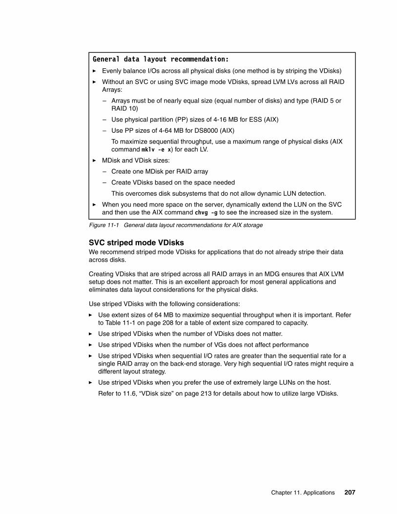
Figure 11-1 General data layout recommendations for AIX storage
SVC striped mode VDisksWe recommend striped mode VDisks for applications that do not already stripe their data across disks.
Creating VDisks that are striped across all RAID arrays in an MDG ensures that AIX LVM setup does not matter. This is an excellent approach for most general applications and eliminates data layout considerations for the physical disks.
Use striped VDisks with the following considerations:
� Use extent sizes of 64 MB to maximize sequential throughput when it is important. Refer to Table 11-1 on page 208 for a table of extent size compared to capacity.
� Use striped VDisks when the number of VDisks does not matter.
� Use striped VDisks when the number of VGs does not affect performance
� Use striped VDisks when sequential I/O rates are greater than the sequential rate for a single RAID array on the back-end storage. Very high sequential I/O rates might require a different layout strategy.
� Use striped VDisks when you prefer the use of extremely large LUNs on the host.
Refer to 11.6, “VDisk size” on page 213 for details about how to utilize large VDisks.
General data layout recommendation:� Evenly balance I/Os across all physical disks (one method is by striping the VDisks)
� Without an SVC or using SVC image mode VDisks, spread LVM LVs across all RAID Arrays:
– Arrays must be of nearly equal size (equal number of disks) and type (RAID 5 or RAID 10)
– Use physical partition (PP) sizes of 4-16 MB for ESS (AIX)
– Use PP sizes of 4-64 MB for DS8000 (AIX)
To maximize sequential throughput, use a maximum range of physical disks (AIX command mklv -e x) for each LV.
� MDisk and VDisk sizes:
– Create one MDisk per RAID array
– Create VDisks based on the space needed
This overcomes disk subsystems that do not allow dynamic LUN detection.
� When you need more space on the server, dynamically extend the LUN on the SVC and then use the AIX command chvg -g to see the increased size in the system.
Chapter 11. Applications 207

Table 11-1 Extent size as opposed to maximum storage capacity
11.3.4 Database strip size considerations (throughput workload)
It is also worthwhile thinking about the relative strip sizes (a strip is the amount of data written to one “volume” or “container” before going to the next volume or container). Database strip sizes are typically small. Let us assume they are 32 KB. The SVC strip size (called extent) is about 64 MB. The back-end RAID arrays have strip sizes in the neighborhood of 64-512 KB. Then, there is the number of threads performing I/O (assume they are sequential, because if they are random, it does not matter). The number of sequential I/O threads is very important and is often overlooked, but it is a key part of the design to get performance from applications that do their own striping. Comparing striping schemes for a single sequential I/O thread might be appropriate for certain applications, such as backups, extract, transform, and load (ETL) applications, and several scientific/engineering applications, but typically is not appropriate for DB2 or Tivoli Storage Manager.
If we have one thread per “volume or container” doing sequential I/O, using image mode VDisks ensures that the I/O is done sequentially with full strip writes (assuming RAID 5). We think this is how DB2 explicitly stripes its data for performance. With striped VDisks, we might run into situations where two threads are doing I/O to the same back-end RAID array or run into convoy effects that temporarily reduce performance (convoy effects result in longer periods of lower throughput).
Tivoli Storage Manager uses a similar scheme to spread out its I/O, but it also depends on ensuring that the number of client backup sessions is equal to the number of Tivoli Storage Manager storage volumes or containers. Tivoli Storage Manager performance issues can be improved by using LVM to spread out the I/Os (called PP striping), because it is difficult to control the number of client backup sessions. For this situation, a good approach is to use striped VDisks rather than image mode VDisks. The perfect situation for Tivoli Storage Manager is n client backup sessions going to n containers (each on a separate RAID array).
To summarize, if you are well aware of the application’s I/O characteristics and the storage mapping (from the application all the way to the physical disks), we recommend explicit balancing of the I/Os using image mode VDisks to maximize the application’s striping performance. Normally, using striped VDisks makes sense, balances the I/O well for most situations, and is significantly easier to manage.
11.3.5 LVM volume groups and logical volumes
Without an SVC managing the back-end storage, the administrator must ensure the host operating system aligns its device data partitions or slices with those of the logical drive. Misalignment can result in numerous boundary crossings that are responsible for unnecessary multiple drive I/Os. Certain operating systems do this automatically, and you
Extent size Maximum storage capacity of cluster
16 MB 64 TB
32 MB 128 TB
64 MB 256 TB
128 MB 512 TB
256 MB 1 PB
512 MB 2 PB
208 SAN Volume Controller: Best Practices and Performance Guidelines
just need to know the alignment boundary that they use. Other operating systems, however, might require manual intervention to set their start point to a value that aligns them.
With an SVC managing the storage for the host as striped VDisks, aligning the partitions is easier, because the extents of the VDisk are spread across the MDisks in the MDG. The storage administrator must ensure an adequate distribution.
Understanding how your host-based volume manager (if used) defines and makes use of the logical drives when they are presented is also an important part of the data layout. Volume managers are generally set up to place logical drives into usage groups for their use. The volume manager then creates volumes by carving up the logical drives into partitions (sometimes referred to as slices) and then building a volume from them by either striping or concatenating them to form the desired volume size.
How the partitions are selected for use and laid out can vary from system to system. In all cases, you need to ensure that spreading the partitions is done in a manner to achieve maximum I/Os available to the logical drives in the group. Generally, large volumes are built across a number of different logical drives to bring more resources to bear. You must be careful when selecting logical drives when you do this in order to not use logical drives that will compete for resources and degrade performance.
11.4 When the application does its own balancing of I/Os
In this section, we discuss how to lay out data when the SVC is involved and when there is no SVC.
11.4.1 DB2 I/O characteristics and data structures
DB2 tables are put into DB2 tablespaces. DB2 tablespaces are made up of containers that are identified storage locations, such as a raw device (logical volume) or a file system. DB2 spreads data and I/Os evenly across containers in a tablespace by placing one DB2 extent of data in each container in a round robin fashion. This causes the data and the I/O activity to be spread evenly across all containers in the tablespace. Each container will have the same I/O activity. Thus, you do not use LVM to spread out I/Os across physical disks. Rather, you create a tablespace with one container on each array, which causes DB2 to explicitly balance I/Os, because data is being accessed equally off each array.
As we will see, a single DB2 container resides on a single logical volume; thus, each container of a tablespace (the logical volume, or a file or directory on it) must reside on a single LUN on an array. This storage design achieves the goal of balanced I/Os spread evenly across physical disks. There are also db2logs that do not share the round robin extent design. The db2logs reside on one LV, which is generally spread across all disks evenly.
Note that this storage design is different from that recommended for other applications in general. For example, assuming that we are using a disk subsystem, such as the DS8000, the general best practice is to create RAID arrays of the same type and size (or nearly the same size), then to take one LUN from each array and create a VG, and then to create LVs that are spread across every LUN in the VG. In other words, this is a spread everything (all LVs) across everything (all physical disks) approach. It is better to not use this approach for DB2, because this approach uses probability to balance I/Os across physical disks, while DB2 explicitly assures that I/Os are balanced.
Chapter 11. Applications 209

DB2 also evenly balances I/Os across DB2 database partitions, also known as DPARs, (these DPARs can exist on different AIX logical partitions (LPARs) or systems). The same I/O principles are applied to each DPAR separately.
DB2 also has different options for containers, including:
� Storage Managed Space (SMS) file system directories � Database Managed Space (DMS) file system files � DMS raw � Automatic Storage for DB2 8.2.2
DMS and SMS are DB2 acronyms for Database Managed Space and Storage Managed Space. Think of DMS containers as preallocated storage and SMS containers as dynamic storage.
Note that if we use SMS file system directories, it is important to have one file system (and underlying LV) per container. That is, do not have two SMS file system directory containers in the same file system. Also, for DMS file system files, it is important to have just one file per file system (and underlying LV) per container. In other words, we have only one container per LV. The reason for these restrictions is that we do not have control of where each container resides in the LV; thus, we cannot assure that the LVs are balanced across physical disks.
The simplest way to think of DB2 data layout is to assume that we are using many disks, and we create one container per disk. In general, each container has the same sustained IOPS bandwidth and resides on a set of physically independent physical disks, because each container will be accessed equally by DB2 agents.
DB2 also has different types of tablespaces and storage uses. For example, tablespaces can be created separately for table data, indexes, and DB2 temporary work areas. The principles of storage design for even I/O balance among tablespace containers applies to each of these tablespace types. Furthermore, containers for different tablespace types can be shared on the same array, thus, allowing all database objects to have equal opportunity at using all I/O performance of the underlying storage subsystem and disks. Also note that different options can be used for each container type, for example, DMS file containers might be used for data tablespaces, and SMS file system directories might be used for DB2 temporary tablespace containers.
DB2 connects physical storage to DB2 tables and database structures through the use of DB2 tablespaces. Collaboration between a DB2 DBA and the AIX Administrator (or storage administrator) to create the DB2 tablespace definitions can ensure that the guidance provided for the database storage design is implemented for optimal I/O performance of the storage subsystem by the DB2 database.
Use of Automatic Storage bypasses LVM entirely, and here, DB2 uses disks for containers. So in this case, each disk must have similar IOPS characteristics. We will not describe this option here.
210 SAN Volume Controller: Best Practices and Performance Guidelines

11.4.2 DB2 data layout example
Assume we have one DPAR, a regular tablespace for data, and a temporary tablespace for DB2 temporary work. Further assume that we are using DMS file containers for the regular tablespace and SMS file directories for the DB2 temporary tablespace. This situation provides us two options for LUN and LVM configuration:
� Create one LUN per array for SMS containers and one LUN per array for DMS containers.
� Create one LUN per array. Then, on each LUN, create one LV (and associated file system) for SMS containers and one LV (and associated file system) for DMS containers.
In either case, the number of VGs is irrelevant from a data layout point of view, but one VG is usually easier to administer and has an advantage for the db2log LV. For the file system logs, JFS2 in-line logs balance the I/Os across the physical disks as well. The second approach is more flexible for growth, at least on disk subsystems that do not allow dynamic LUN expansion, because as the database grows, we can increase the LVs as needed. There also does not need to be any initial planning for the size difference between DB2 tables and DB2 temporary space. This is why DB2 practitioners will frequently recommend creating only one LUN on an array, because this storage design provides simplicity while maintaining the highest levels of I/O performance.
For the db2log LV, we have similar options and we can create one LUN per array and then create the LV across all the LUNs.
A second approach to growth is to add another array, the LUNs, and the LVs and allow DB2 to rebalance the data across the containers. This approach also increases the IOPS bandwidth available to DB2. A third approach to growth is to add one or two disks to each RAID array (for disk subsystems that support dynamic RAID array expansion). This approach increases IOPS bandwidth.
So for DB2 and SVC, it makes sense to use image or sequential mode VDisks and use DB2 striping. But for other general applications, we generally recommend using striped VDisks to balance the I/Os, which also has the advantage of eliminating LVM data layout as an issue. We also recommend using SDDPCM instead of IBM Subsystem Device Driver (SDD). Growth can be handled for general applications by dynamically increasing the size of the VDisk and then using chvg -g for LVM to see the increased size. For DB2, growth can be handled by adding another container (a sequential or image mode VDisk) and allowing DB2 to restripe the data across the VDisks.
11.4.3 Striped VDisk recommendation
While we have recommended that applications that can handle their own striping are set up not to use the striping provided by SVC, it usually does little harm to do both kinds of striping. The striping provided by the application can be ineffective.
One danger of multiple striping upon striping is the “beat” effect, similar to the harmonics of music. One striping method reverses (undoes) the benefits of the other striping method. However, the beat effect is easy to avoid by ensuring a wide difference in stripe granularities.
You can design a careful test of an application configuration to ensure that application striping is optimal when using image mode disks, therefore, supplying maximum performance. However, in a production environment, the usual scenario is a hodgepodge of different databases, built at different times for different purposes, housed in a large and growing number of tablespaces. Under these conditions, it is very difficult to ensure that application striping continues to work well in terms of distributing the total load across the whole set of physical disks.
Chapter 11. Applications 211

Therefore, we recommend SVC striping even when the application does its own unless you have carefully planned and tested the application and the entire environment. This approach adds a great deal more robustness to the situation. It now becomes easy to accommodate completely new databases and tablespaces with no special planning and without disrupting the balance of work. Also, the extra level of striping ensures that the load will be balanced even if the application striping fails. Perhaps most important, this recommendation lifts a significant burden from the database administrator, because good performance can be achieved with much less care and planning.
11.5 Data layout with the AIX virtual I/O (VIO) server
The purpose of this section is to describe strategies to get the best I/O performance by evenly balancing I/Os across physical disks when using the VIO Server.
11.5.1 Overview
In setting up storage at a VIO server (VIOS), a broad range of possibilities exist for creating VDisks and serving them up to VIO clients (VIOCs). The obvious consideration is to create sufficient storage for each VIOC. Less obvious but equally important is getting the best use of the storage. Performance and availability are of paramount importance. There are typically internal Small Computer System Interface (SCSI) disks (typically used for the VIOS operating system) and SAN disks. Availability for disk is usually handled via RAID on the SAN or via SCSI RAID adapters on the VIOS. We will assume here that any internal SCSI disks are used for the VIOS operating system and possibly for the VIOC’s operating systems. Furthermore, we will assume that the applications are configured so that the limited I/O will occur to the internal SCSI disks on the VIOS and to the VIOC’s rootvgs. If you expect your rootvg will have a significant IOPS rate, you can configure it in the same fashion as we recommend for other application VGs later.
VIOS restrictions There are two types of VDisks that you can create on a VIOS: physical volume (PV) VSCSI HDisks and logical volume (LV) VSCSI HDisks.
PV VSCSI HDisks are entire LUNs from the VIOS point of view, and if you are concerned about failure of a VIOS and have configured redundant VIOS for that reason, you must use PV VSCSI HDisks. So, PV VSCSI HDisks are entire LUNs that are VDisks from the VIOC point of view.
An LV VSCSI HDisk cannot be served up from multiple VIOSs. LV VSCSI HDisks reside in LVM VGs on the VIOS and cannot span PVs in that VG, nor be striped LVs.
VIOS queue depthFrom a performance point of view, the queue_depth of VSCSI HDisks is limited to 3 at the VIOC. This limits the IOPS bandwidth to approximately 300 IOPS (assuming an average I/O service time of 10 ms). Thus, you need to configure a sufficient number of VSCSI HDisks to get the IOPS bandwidth needed. The queue depth limit changed in Version 1.3 of the VIOS (August 2006) to 256; although, you still need to worry about the IOPS bandwidth of the back-end disks. When possible, set the queue depth of the VIOC HDisks to match that of the VIOS HDisk to which it maps.
If you are at software levels lower than AIX 5.3 ML5 and VIOS 1.3, the queue_depth of VSCSI HDisks is limited to 3 at the VIOC. This limits the IOPS bandwidth to approximately
212 SAN Volume Controller: Best Practices and Performance Guidelines
300 IOPS (assuming an average I/O service time of 10 ms). Thus, you need to configure a sufficient number of VSCSI HDisks to get the IOPS bandwidth needed. But, at the subject levels, queue_depth for the VIOC HDisks is configurable up to 256. When possible, set the queue depth of the VIOC HDisks to match that of the VIOS HDisk to which it maps.
11.5.2 Data layout strategies
You can use the SVC or AIX LVM (with appropriate configuration of vscsi disks at the VIOS) to balance the I/Os across the back-end physical disks. So, here are the options to balance the I/Os evenly across all arrays on the back-end disk subsystems:
When using an SVC:
� You create just one LUN per array on the back-end disk in each MDG (the normal practice is to have RAID arrays of the same type and size, or nearly the same size, and same performance characteristics in an MDG).
� You create striped VDisks on the SVC that are striped across all back-end LUNs.
� When you do this, the LVM setup does not matter, and you can use PV vscsi HDisks and redundant VIOSs or LV vscsi HDisks (if you are not worried about VIOS failure).
When using redundant VIOSs and no SVC (consequently, using PV vscsi HDisks):
� Create one LUN on each array for each VIOC (VIO Client LPAR).
� Put all the LUNs in one VG on the VIOC.
� Spread LVM LVs across all PVs in the VG.
When using a single VIOS and no SVC (assuming that you will use LVM on the VIOS to create LV vscsi HDisks):
� Create a LUN on each array (assuming the arrays are of the same type and size, or nearly the same size, and have the same I/O performance characteristics) and assign to the VIOS.
� For each VIOC LPAR, create a LVM LV on each LUN of the same size and assign these LV vscsi HDisks to the VIOC LPAR. Assuming the VIOCs require different storage capacities, then the LV sizes will be different for each VIOC.
� At the VIOC, put all the LV vscsi HDisks into one VG.
� Spread each LV at each VIOC across all the PVs in the VG.
These strategies assume only that I/Os to an LV are random across the LV.
11.6 VDisk size
Larger VDisks might need more disk buffers and larger queue_depths depending on the I/O rates; however, there is a large benefit of less AIX memory and fewer path management resources used. It is worthwhile to tune the queue depths and adapter resources for this purpose. It is preferable to use fewer large LUNs, because it is easy to increase the queue_depth (this does require application downtime) and disk buffers, because handling more LUNs requires a considerable amount of OS resources. Not all operating systems have this tuning capability (namely Windows, so for operating systems without that capability, more smaller LUNs offer a performance benefit).
Chapter 11. Applications 213
11.7 Failure boundaries
There is one more thing to consider, and that is failure boundaries. If all of the LUNs are spread across all physical disks (and all RAID arrays, in other words, you are using striped VDisks), and if you lose a single RAID array, you lose all your data.
So there are situations in which you probably want to limit the spread for certain applications or groups of applications. You might have a group of applications where if one application fails, none of the applications can do any productive work. This is a good group of applications to share the same set of back-end disks due to the failure boundary. Alternatively, if you have two applications, and one application is down, you can still run the business (although, obviously some function will be gone due to the failed application). But if both applications are down, it will cost the business a lot, and then you probably want to have separate failure boundaries for them. This trades off productive use of the resources with the availability impact to the business and is an important consideration in setting up the storage.
214 SAN Volume Controller: Best Practices and Performance Guidelines
Chapter 12. Monitoring
The examples in this chapter were taken from TotalStorage Productivity Center (TPC) V3.3, which was released in July 2007.
This chapter will not discuss how to use TPC to monitor your storage controllers, switches, and host data. In 12.1, “Configuring TPC to analyze the SVC” on page 216, we show you how to set up TPC to monitor your SVC environment. We assume that you already have TPC monitoring your other SAN equipment.
If you have an earlier version of TPC installed, you might still be able to reproduce the reports described here.
12
© Copyright IBM Corp. 2008. All rights reserved. 215
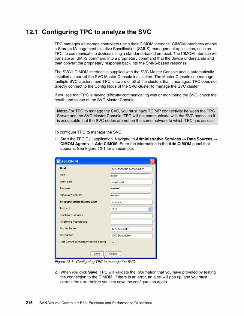
12.1 Configuring TPC to analyze the SVC
TPC manages all storage controllers using their CIMOM interface. CIMOM interfaces enable a Storage Management Initiative Specification (SMI-S) management application, such as TPC, to communicate to devices using a standards-based protocol. The CIMOM interface will translate an SMI-S command into a proprietary command that the device understands and then convert the proprietary response back into the SMI-S-based response.
The SVC’s CIMOM interface is supplied with the SVC Master Console and is automatically installed as part of the SVC Master Console installation. The Master Console can manage multiple SVC clusters, and TPC is aware of all of the clusters that it manages. TPC does not directly connect to the Config Node of the SVC cluster to manage the SVC cluster.
If you see that TPC is having difficulty communicating with or monitoring the SVC, check the health and status of the SVC Master Console.
To configure TPC to manage the SVC:
1. Start the TPC GUI application. Navigate to Administrative Services → Data Sources → CIMOM Agents → Add CIMOM. Enter the information in the Add CIMOM panel that appears. See Figure 12-1 for an example.
Figure 12-1 Configuring TPC to manage the SVC
2. When you click Save, TPC will validate the information that you have provided by testing the connection to the CIMOM. If there is an error, an alert will pop up, and you must correct the error before you can save the configuration again.
Note: For TPC to manage the SVC, you must have TCP/IP connectivity between the TPC Server and the SVC Master Console. TPC will not communicate with the SVC nodes, so it is acceptable that the SVC nodes are not on the same network to which TPC has access.
216 SAN Volume Controller: Best Practices and Performance Guidelines

3. After the connection has been successfully configured, TPC must run a CIMOM Discovery (under Administrative Services → Discovery → CIMOM) before you can set up performance monitoring or before the SVC cluster will appear in the Topology Viewer.
12.2 Using the TPC to verify fabric configuration
After TPC has probed the SAN environment, it takes the information from all the SAN components (switches, storage controllers, and hosts) and automatically builds a graphical display of the SAN environment. This graphical display is available via the Topology Viewer option on the TPC navigation tree.
The information on the Topology Viewer panel is current as of the successful resolution of the last problem. By default, TPC will probe the environment daily; however, you can execute an unplanned or immediate probe at any time.
Normally, the probe takes less than five minutes to complete. If you are analyzing the environment for problem determination, we recommend that you execute an ad hoc probe to ensure that you have the latest up-to-date information on the SAN environment. Make sure that the probe completes successfully.
12.2.1 Verifying SVC node ports
It is important that each SVC node port is connected to switches in your SAN fabric. If any SVC node port is not connected, each node in the cluster will display an error on the LCD display (probably, error 1060). TPC will also show the health of the cluster as a warning in the Topology Viewer.
It is equally important to ensure that:
� You have at least one port from each node in each fabric.
� You have an equal number of ports in each fabric from each node; that is, do not have three ports in fabric 1 and only one port in fabric two for an SVC node.
Figure 12-2 on page 218 shows using TPC (under IBM TotalStorage Productivity Center → Topology → Storage) to verify that we have an even number of ports in each fabric. The example configuration shows that:
� Our SVC is connected to two fabrics (we have named our fabrics FABRIC-2GBS and FABRIC-4GBS).
� We have four SVC nodes in this cluster. TPC has organized our switch ports so that each column represents a node, which you can see, because worldwide port name (WWPN) has similar numbers.
� We have an even number of ports in each switch. Figure 12-2 on page 218 shows the links to each switch at the same time. It might be easier to validate this setup by clicking on one switch at a time (see Figure 12-5 on page 221).
Note: The SVC Config Node (that owns the IP address for the cluster) has a 10 session SSH limit. TPC will use one of these sessions while interacting with the SVC. You can read more information about the session limit in “Connection limitations” on page 35.
Chapter 12. Monitoring 217

Figure 12-2 Checking the SVC ports to ensure they are connected to the SAN fabric
TPC can also show us where our host and storage are in our fabric and which switches the I/Os will go through when I/Os are generated from the host to the SVC or from the SVC to the storage controller.
For redundancy, all storage controllers must be connected to at least two fabrics, and those same fabrics need to be the ones to which the SVC is connected.
Figure 12-3 on page 219 shows our DS4500 is also connected to fabrics FABRIC-2GBS and FABRIC-4GBS as we planned.
Information: When we cabled our SVC, we intended to connect ports 1 and 3 to one switch (IBM_2109_F32) and ports 2 and 4 to the other switch (swd77). We thought that we were really careful about labeling our cables and configuring our ports.
TPC showed us that we did not configure the ports this way, and additionally, we made two mistakes. Figure 12-2 shows that we:
� Correctly configured all four nodes with port 1 to switch IBM_2109_F32
� Correctly configured all four nodes with port 2 to switch swd77
� Incorrectly configured two nodes with port 3 to switch swd77
� Incorrectly configured two nodes with port 4 to switch IBM_2109_F32
Information: Our DS4500 was shared with other users, so we were only able to use two of the available four ports. The other two ports were used by a different SAN infrastructure.
218 SAN Volume Controller: Best Practices and Performance Guidelines

Figure 12-3 Checking that your storage is in each fabric
12.2.2 Ensure that all SVC ports are online
Information in the Topology Viewer can also confirm the health and status of the SVC and the switch ports. When you look at the Topology Viewer, TPC will show a Fibre port with a box next to the WWPN. If this box has a black line in it, the port is connected to another device. Table 12-1 shows an example of the ports with their connected status.
Table 12-1 TPC port connection status
Figure 12-2 on page 218 shows an example where all the TPC ports are connected and the switch ports are healthy.
Figure 12-4 on page 220 shows an example where the SVC ports are not healthy. In this example, the two ports that have a black line drawn between the switch and the SVC node port are in fact down.
Because TPC knew to where these two ports were connected on a previous probe (and, thus, they were previously shown with a green line), the probe discovered that these ports were no longer connected, which resulted in the green line becoming a black line.
TPC port view Status
This is a port that is connected.
This is a port that is not connected.
Chapter 12. Monitoring 219
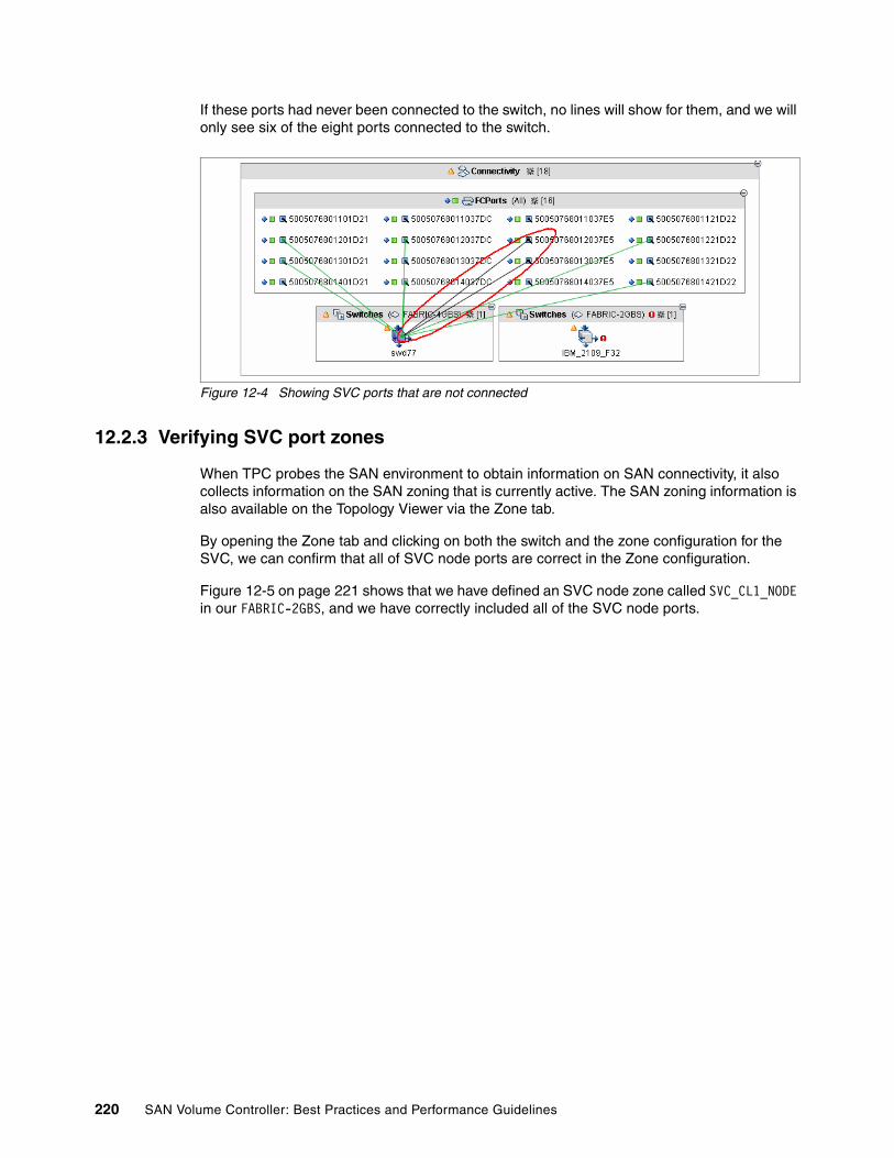
If these ports had never been connected to the switch, no lines will show for them, and we will only see six of the eight ports connected to the switch.
Figure 12-4 Showing SVC ports that are not connected
12.2.3 Verifying SVC port zones
When TPC probes the SAN environment to obtain information on SAN connectivity, it also collects information on the SAN zoning that is currently active. The SAN zoning information is also available on the Topology Viewer via the Zone tab.
By opening the Zone tab and clicking on both the switch and the zone configuration for the SVC, we can confirm that all of SVC node ports are correct in the Zone configuration.
Figure 12-5 on page 221 shows that we have defined an SVC node zone called SVC_CL1_NODE in our FABRIC-2GBS, and we have correctly included all of the SVC node ports.
220 SAN Volume Controller: Best Practices and Performance Guidelines
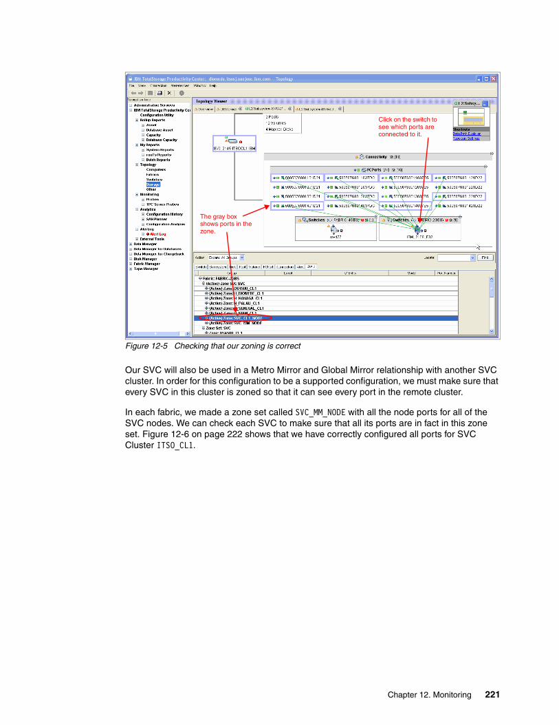
Figure 12-5 Checking that our zoning is correct
Our SVC will also be used in a Metro Mirror and Global Mirror relationship with another SVC cluster. In order for this configuration to be a supported configuration, we must make sure that every SVC in this cluster is zoned so that it can see every port in the remote cluster.
In each fabric, we made a zone set called SVC_MM_NODE with all the node ports for all of the SVC nodes. We can check each SVC to make sure that all its ports are in fact in this zone set. Figure 12-6 on page 222 shows that we have correctly configured all ports for SVC Cluster ITSO_CL1.
The gray box shows ports in the zone.
Click on the switch to see which ports are connected to it.
Chapter 12. Monitoring 221

Figure 12-6 Verifying Metro Mirror and Global Mirror zones
12.2.4 Verifying paths to storage
TPC 3.3 introduced a new feature called the Data Path View. This view can be used to see the path between two objects and it shows the objects and the switch fabric in one view.
Using the Data Path View, we can see that mdisk1 in SVC ITSOCL1 is available through all the SVC ports and trace that connectivity to its logical unit number (LUN) ST-7S10-5. This is shown in Figure 12-7 on page 223.
What is not shown in Figure 12-7 on page 223 is that you can hover the MDisk, LUN, and switch ports and get both health and performance information about these components. This enables you to verify the status of each component to see how well it is performing.
Shift click on each zone, to see all the ports.
222 SAN Volume Controller: Best Practices and Performance Guidelines
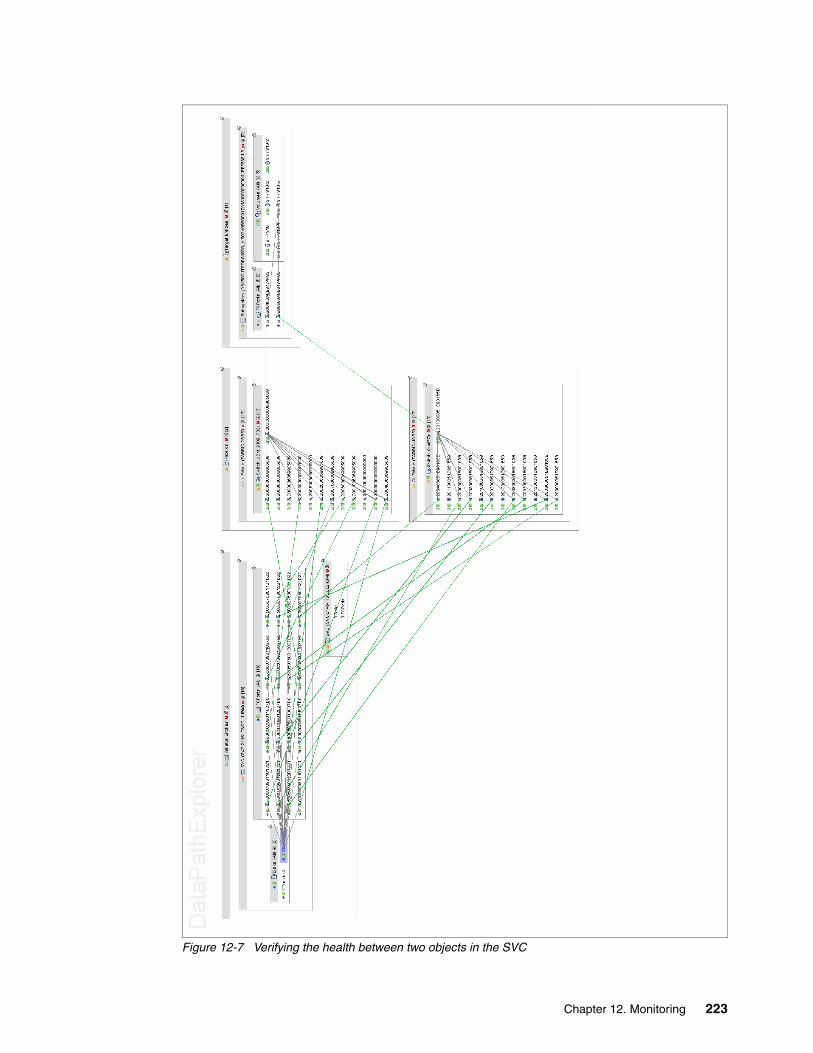
Figure 12-7 Verifying the health between two objects in the SVC
Chapter 12. Monitoring 223
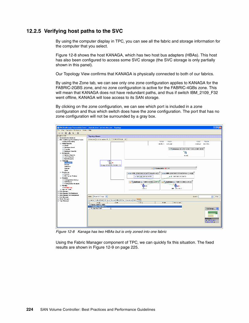
12.2.5 Verifying host paths to the SVC
By using the computer display in TPC, you can see all the fabric and storage information for the computer that you select.
Figure 12-8 shows the host KANAGA, which has two host bus adapters (HBAs). This host has also been configured to access some SVC storage (the SVC storage is only partially shown in this panel).
Our Topology View confirms that KANAGA is physically connected to both of our fabrics.
By using the Zone tab, we can see only one zone configuration applies to KANAGA for the FABRIC-2GBS zone, and no zone configuration is active for the FABRIC-4GBs zone. This will mean that KANAGA does not have redundant paths, and thus if switch IBM_2109_F32 went offline, KANAGA will lose access to its SAN storage.
By clicking on the zone configuration, we can see which port is included in a zone configuration and thus which switch does have the zone configuration. The port that has no zone configuration will not be surrounded by a gray box.
Figure 12-8 Kanaga has two HBAs but is only zoned into one fabric
Using the Fabric Manager component of TPC, we can quickly fix this situation. The fixed results are shown in Figure 12-9 on page 225.
224 SAN Volume Controller: Best Practices and Performance Guidelines

Figure 12-9 Kanaga with the zoning fixed
The Data Path Viewer in TPC can also be used to check to confirm path connectivity between a disk that an operating system sees and the VDisk that the SVC provides.
Figure 12-10 on page 226 shows two diagrams for the path information relating to host KANAGA:
� The top (left) diagram shows the path information before we fixed our zoning configuration. It confirms that KANAGA only has one path to the SVC VDisk vdisk4. Figure 12-8 on page 224 confirmed that KANAGA has two HBAs and that they are connected to our SAN fabrics. From this panel, we can deduce our problem is likely to be a zoning configuration problem.
� The lower (right) diagram is the result that shows the zoning fixed.
Figure 12-10 on page 226 does not show us that you can hover over each component to also get health and performance information, which might also be useful when you perform problem determination and analysis.
Chapter 12. Monitoring 225

Figure 12-10 Viewing host paths to the SVC
226 SAN Volume Controller: Best Practices and Performance Guidelines
12.3 Methods for collecting data
TPC can collect performance information for all of the components that make up your SAN. With the performance information about the switches and storage, it is possible to view the end-to-end performance for a specific host in our SAN environment.
There are three methods of using the performance data that TPC collects:
� Using the TPC GUI to manage fabric and disk performance
By default, the TPC GUI is installed on the TPC server. You can also optionally install the TPC GUI on any supported Windows or UNIX workstation by running the setup on disk1 of the TPC media and choosing a custom installation.
By using the TPC GUI, you can monitor the performance of the:
– Switches by navigating to Fabric Manager → Reporting → Switch Performance
– Storage controllers by navigating to Disk Manager → Reporting → Storage Subsystem Performance
Both options are in the TPC navigation tree on the left side of GUI.
The reports under these menu options provide the most detailed information about the performance of the devices.
� Using the TPC GUI with the Data Path Viewer
With TPC 3.3, there is a new Data Path Viewer display, which enables you to see the end-to-end performance between:
– A host and its disks (VDisks if they are SVC or LUNs if there is a storage controller)
– The SVC and the storage controllers that provide LUNs
– A storage controller and all the hosts to which it provides storage (including the SVC)
With the Data Path Viewer, all the information and the connectivity between a source (Initiator Entity) and a target (Target Entity) are shown in one display.
Turning on the Topology Viewer Health, Performance, and Alert overlays, you can hover over each component to get a full understanding of how they are performing and their health.
To use the Data Path Viewer, navigate to the Topology Viewer (under IBM TotalStorage Productivity Center → Topology), right-click a computer or storage controller and select Open DataPath View.
� Using the TPC command line interface (CLI) TPCTOOL
The TPCTOOL command line interface enables you to script extracting data out of TPC so that you can do more advanced performance analysis. This is particularly useful if you want to include multiple performance metrics about one or more devices on one report.
For example, if you have an application that spans multiple hosts with multiple disks coming from multiple controllers, you can use TPCTOOL to collect all the performance information from each component and group all of it together onto one report.
Using TPCTOOL assumes you have an advanced understanding of TPC and requires scripting to take full advantage of it. We recommend that you use at least TPC V3.1.2 if you plan on using the CLI interface.
Chapter 12. Monitoring 227

12.3.1 Setting up TPC to collect performance information
TPC performance collection is either turned on or turned off. You do not need to specify the performance information that you want to collect. TPC will collect all performance counters that the SVC (or storage controller) provides and insert them into the TPC database. Once the counters are there, you can report on the results using any of the three methods described in the previous section.
To enable the performance collection, navigate to Disk Manager → Monitoring and right-click Storage Performance Monitors.
We recommend that you create a separate performance monitor for each CIMOM from which you want to collect performance data. Each CIMOM provides different sampling intervals, and if you combine all of your different storage controllers into one performance collection, the sample interval might not be as granular as you want.
Additionally, by having separate performance monitor collections, you can start and stop individual monitors as required.
12.3.2 Viewing TPC-collected information
TPC collects and reports on many statistics as recorded by the SVC nodes. With these statistics, you can get general cluster performance information or more detailed specific VDisk or MDisk performance information.
An explanation of the metrics and how they are calculated is available in Appendix A of the TotalStorage Productivity Center User Guide located at this Web site:
http://publib.boulder.ibm.com/infocenter/tivihelp/v4r1/topic/com.ibm.itpc.doc/tpcugd31389.htm
The TPC GUI interface provides you with an easy intuitive method of querying the TPC database to obtain information about many of the counters that it stores. One limitation of the TPC GUI is that you can only report on “like” counters at one time, for example, I/O rates, response times, or data rates.
You also cannot include dissimilar counters in the same report, nor can you include information from related devices on the same report. For example, you cannot combine port utilization from a switch with the host data rate as seen on the SVC. This information can only be provided in separate reports with the TPC GUI.
If you use the TPC command line interface, you will be able to collect all of the individual metrics on which you want to report and massage that data into one report.
Note: Make sure that your TPC server, SVC Master Console, and SVC cluster are set with the correct times for their time zones.
If your SVC is configured for Coordinated Universal Time (UTC), ensure that it is in fact on UTC time and not local time. TPC will adjust the time on the performance data that it receives before inserting the data in the TPC database.
If the time does not match the time zone, it is difficult to compare performance among objects, for example, the switch performance or the storage controller performance.
228 SAN Volume Controller: Best Practices and Performance Guidelines

When starting to analyze the performance of the SVC environment to identify a performance problem, we recommend that you identify all of the components between the two systems and verify the performance of the smaller components.
Thus, traffic between a host, the SVC nodes, and a storage controller goes through these paths:
1. The host generates the I/O and transmits it on the fabric.
2. The I/O is received on the SVC node ports.
3. If the I/O is a write I/O:
a. The SVC node writes the I/O to the SVC node cache.
b. The SVC node sends a copy to its partner node to write to the partner node’s cache.
c. If the I/O is part of a Metro Mirror and Global Mirror, a copy needs to go to the target VDisk of the relationship.
d. If the I/O is part of a FlashCopy and the FlashCopy block has not been copied to the target VDisk, this action needs to be scheduled.
4. If the I/O is a read I/O:
a. The SVC needs to check the cache to see if the Read I/O is already there.
b. If the I/O is not in the cache, the SVC needs to read the data from the physical LUNs.
5. At some point, write I/Os will be sent to the storage controller.
6. The SVC might also do some read ahead I/Os to load the cache in case the next read I/O from the host is the next block.
TPC can help you report on most of these steps so that it is easier to identify where a bottleneck might exist.
Cluster, I/O Group, and nodesThe TPC cluster performance information is useful to get an overall idea of how the cluster is performing and to get an understanding of the workload passing through your cluster.
The I/O Group and nodes reports enable you to drill-down into the health of the cluster and obtain a more granular understanding of the performance.
The available reports fit into the following categories.
SVC node resource performanceThese reports enable you to understand the workload on the cluster resources, particularly the load on CPU and cache memory. There is also a report that shows the traffic between nodes.
Figure 12-11 on page 230 shows an example of several of the available I/O Group resource performance metrics. In this example, we generated excessive I/O to our storage controller (of which the SVC was unaware) together with some excess load on two hosts that each had 11 VDisks from our SVC cluster. The result of this exercise was to show where a storage controller is under stress and how this is reflected in the TPC results.
Chapter 12. Monitoring 229

Figure 12-11 Multiple I/O Group resource performance metrics
An important metric in this report is the CPU utilization (in dark blue). The CPU Utilization reports give you an indication of how busy the cluster CPUs are. A continual high CPU Utilization rate indicates a busy cluster. If the CPU utilization remains constantly high, it might be time to increase the cluster by adding more resources.
You can add cluster resources by adding another I/O Group to the cluster (two nodes) up to the maximum of four I/O Groups per cluster.
After there are four I/O Groups in a cluster and high CPU utilization is still indicated in the reports, it is time to build a new cluster and consider either migrating some storage to the new cluster or servicing new storage requests from it.
We recommend that you plan additional resources for the cluster if your CPU utilization indicates workload continually above 70%.
The cache memory resource reports provide an understanding of the utilization of the SVC cache. These reports provide you with an indication of whether the cache is able to service and buffer the current workload.
In Figure 12-11, you will notice that there is an increase in the Write-cache Delay Percentage and Write-cache Flush Through Percentage and a drop in the Write-cache Hits Percentage, Read Cache Hits, and Read-ahead percentage of cache hits. This change is noted about halfway through the graph.
This change in these performance metrics together with an increase in back-end response time shows that the storage controller is heavily burdened with I/O, and at this time interval, the SVC cache is probably full of outstanding write I/Os. (We expected this result with our test run.) Host I/O activity will now be impacted with the backlog of data in the SVC cache and with any other SVC workload that is going on to the same MDisks (FlashCopy and Global/Metro Mirror).
230 SAN Volume Controller: Best Practices and Performance Guidelines

If cache utilization is a problem, you can add additional cache to the cluster by adding an I/O Group and moving VDisks to the new I/O Group.
SVC fabric performanceThe SVC fabric performance reports help you understand the SVC’s impact on the fabric and give you an indication of the traffic between:
� SVC and hosts that receive storage� SVC and back-end storage� Nodes in the SVC cluster
These reports can help you understand if the fabric might be a performance bottleneck and if upgrading the fabric can lead to performance improvement.
Figure 12-12 Port receive and send data rate for each I/O Group
Figure 12-12 and Figure 12-13 on page 232 show two versions of port rate reports. Figure 12-12 shows the overall SVC node port rates for send and receive traffic. With a 2 Gb per second fabric, these rates are well below the throughput capability of this fabric, and thus the fabric is not a bottleneck here.
Figure 12-13 on page 232 shows the port traffic broken down into host, node, and disk traffic. During our busy time as reported in Figure 12-11 on page 230, we can see that host port traffic drops while disk port traffic continues. This indicates that the SVC is communicating with the storage controller, possibly flushing outstanding I/O write data in the cache and performing other non-host functions, such as FlashCopy and Metro Mirror and Global Mirror copy synchronization.
Chapter 12. Monitoring 231

Figure 12-13 Total port to disk, host, and local node report
Figure 12-14 on page 233 shows an example TPC report looking at port rates between SVC nodes, hosts and disk storage controllers. This report shows low queue and response times, indicating that the nodes do not have a problem communicating with each other.
If this report showed usually high queue and response times, our write activity (because each node communicates to each other node over the fabric) is affected.
Unusually high numbers in this report indicate:
� SVC node or port problem (unlikely)� Fabric switch congestion (more likely)� Faulty fabric ports or cables (most likely)
232 SAN Volume Controller: Best Practices and Performance Guidelines
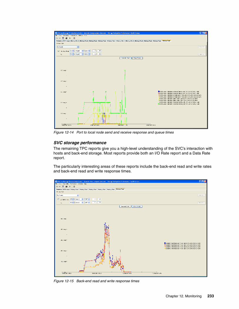
Figure 12-14 Port to local node send and receive response and queue times
SVC storage performanceThe remaining TPC reports give you a high-level understanding of the SVC’s interaction with hosts and back-end storage. Most reports provide both an I/O Rate report and a Data Rate report.
The particularly interesting areas of these reports include the back-end read and write rates and back-end read and write response times.
Figure 12-15 Back-end read and write response times
Chapter 12. Monitoring 233

In Figure 12-15 on page 233, we see an unusual spike in back-end response time for both read and write operations, and this spike is consistent for both our I/O Groups. This report confirms that we are receiving poor response from our storage controller and explains our lower than expected host performance.
Our cache resource reports (in Figure 12-11 on page 230) also show an unusual pattern in cache usage during the same time interval. Thus, we can attribute the cache performance to be a result of the poor back-end response time that the SVC is receiving from the storage controller.
Here is a summary of the available cluster reports in TPC 3.3:
� Overall Data Rates and I/O Rates
� Backend I/O Rates and Data Rates
� Response Time and Backend Response Time
� Transfer Size and Backend Transfer Size
� Disk to Cache Transfer Rate
� Queue Time
� Overall Cache Hit Rates and Write Cache Delay
� Readahead and Dirty Write cache
� Write cache overflow, flush-through, and write-through
� Port Data Rates and I/O Rates
� CPU Utilization
� Data Rates, I/O Rates, Response Time, and Queue Time for:
– Port to Host – Port to Disk– Port to Local Node – Port to Remote Node
� Global Mirror Rates
� Peak Read and Write Rates
Managed Disk Group, Managed Disk, and Volumes reportThe Managed Disk Group, Managed Disk, and Volumes report enables you to report on the performance of storage both from back end and front end.
By including a VDisk on a report, together with the LUNs from the storage controllers (which in turn are the MDisks over which the VDisks can be striped), you can see the performance that a host is receiving (via the VDisks) together with the impact on the storage controller (via the LUNs).
Figure 12-16 on page 235 shows a VDisk named IOTEST and the associated LUNs from our DS4000 storage controller. We can see which of the LUNs are being used while IOTEST is being used.
234 SAN Volume Controller: Best Practices and Performance Guidelines

Figure 12-16 Viewing VDisk and LUN performance
12.3.3 Using TPC to alert on performance constraints
Along with reporting on SVC performance, TPC can also generate alerts when performance has not met or has exceeded a defined threshold.
Like most TPC tasks, the alerting can report to:
� Simple Network Management Protocol (SNMP), which can enable you to send a trap to an upstream systems management application. The SNMP trap can then be used with other events occurring within the environment to help determine the root cause of an SNMP trap generated by the SVC.
For example, if the SVC reported to TPC that a Fibre Channel port went offline, it might result from a switch failure. This “port failed” trap, together with the “switch offline” trap, can be analyzed by a systems management tool, which discovers that this is a switch problem and not an SVC problem, and calls the switch technician.
� TEC Event. Select to send a Tivoli Enterprise Console® (TEC) event.
� Login Notification. Select to send the alert to a TotalStorage Productivity Center user. The user receives the alert upon logging in to TotalStorage Productivity Center. In the Login ID field, type the user ID.
� UNIX or Windows NT® Server system event logger.
� Script. The script option enables you to run a defined set of commands that might help address this event. For example, simply open a trouble ticket in your helpdesk ticket system.
� Notification by e-mail. TPC will send an email to each person listed.
Chapter 12. Monitoring 235

Several useful alert events that you should set include:
� CPU utilization threshold
The CPU utilization report alerts you when your SVC nodes become too busy. If this alert is generated too often, it might be time to upgrade your cluster with additional resources.
� Overall port response time threshold
The port response time alert can let you know when the SAN fabric is becoming a bottleneck. If the response times are consistently poor, perform additional analysis of your SAN fabric.
� Overall back-end response time threshold
An increase in back-end response time might indicate that you are overloading your back-end storage.
236 SAN Volume Controller: Best Practices and Performance Guidelines
Chapter 13. Maintenance
As with any piece of enterprise storage equipment, the IBM SAN Volume Controller (SVC) is not a completely “hands-off” device. It requires configuration changes to meet growing needs, updates to software for enhanced performance, features, and reliability, and the tracking of all the data that you used to configure your SVC.
13
© Copyright IBM Corp. 2008. All rights reserved. 237
13.1 Configuration and change tracking
The IBM San Volume Controller provides great flexibility to your storage configuration that you do not otherwise have. However, with the flexibility comes an added layer of configuration that is not present in a “normal” SAN. However, your total administrative burden often decreases, because very few changes are necessary on your disk arrays when the SVC manages them.
There are many tools and techniques that you can use to prevent your SVC installation from spiralling out of control. What is most important is what information you track, not how you track it. For smaller installations, everything can be tracked on simple spreadsheets. In environments with several clusters, hundreds of hosts, and a whole team of administrators, more automated solutions, such as TotalStorage Productivity Manager or custom databases might be required.
This section will not go over so much how to track your changes, because there are far too many tools and methods available to cover here. Rather, we discuss what sort of information is extremely useful to track. You can decide for yourself what is the best method of doing so.
In theory, your documentation is sufficient for any engineer, who is skilled with the products that you own, can take a copy of all of your configuration information and use it to create a functionally equivalent copy of the environment from scratch. If your documentation does not allow you to achieve this goal, you are not tracking enough information.
It is best to create this documentation as you install your solution. Putting this information together after deployment is likely to be a tedious, boring, and error-prone task.
The following sections provide what we believe to be the minimum documentation needed for an SVC solution. Do not view it as an exhaustive list; you might have additional business requirements that require other data to be tracked.
13.1.1 SAN
Tracking how your SAN is configured is going to be pretty important.
SAN diagramThe most basic piece of SAN documentation is the SAN diagram. If you ever call support asking for help with your SAN, you can be sure that the SAN diagram is likely to be one of the first things that you are asked to produce.
Maintaining a proper SAN diagram is not as difficult as it sounds. It is not necessary for the diagram to show every last host and the location of every last port; this information is more properly collected (and easier to read) in other places. To understand how difficult an overly detailed diagram is to read, refer to Figure 13-1 on page 239.
Note: Do not store all change tracking and SAN, SVC, and storage inventory information on the SAN itself.
238 SAN Volume Controller: Best Practices and Performance Guidelines

Figure 13-1 An overly detailed SAN diagram
Instead, a SAN diagram needs to only include every switch, every storage device, all inter-switch links (ISLs), along with how many there are, and some representation of which switches have hosts connected to them. An example is shown in Figure 13-2 on page 240. In larger SANs with many storage devices, the diagram can still be too large to print without a large-format printer, but it can still be viewed on a panel using the zoom feature. We suggest a tool, such as Microsoft Visio®, to create your diagrams. Do not worry about finding fancy stencils or official shapes, because your diagram does not need to show exactly into which port everything is plugged. You can use your port inventory for that. Your diagram can be appropriately simple. You will notice that our sample diagram just uses simple geometric shapes and “standard” stencils to represent a SAN.
Note: These SAN diagrams are just sample diagrams. They do not necessarily depict a SAN that you actually want to deploy.
Chapter 13. Maintenance 239

Figure 13-2 A more useful diagram of approximately the same SAN
Notice that in our simplified diagram, individual hosts do not appear; instead, we merely note which switches have connections to hosts. Also, because typically SANs are symmetrical in most installations, one diagram will suffice for both. The numbers inside the switch boxes denote the Domain IDs.
Port inventoryAlong with the SAN diagram, an inventory of “what is supposed to be plugged in where” is also quite important. Again, you can create this inventory manually or generate it with automated tools. Before using automated tools, remember that it is important that your inventory contains not just what is currently plugged into the SAN, but also what is supposed to be attached to the SAN. If a server has lost its SAN connection, merely looking at the current status of the SAN will not tell you where it was supposed to be attached.
This inventory must exist in a format that can be exported and sent to someone else and retained in an archive for long-term tracking.
Switch 1, 2 Switch 5, 6Switch 3, 4
SVC 1 (8 nodes)
Switch 21, 22
Switch 19, 20
Switch 17, 18
Switch 13, 14
Switch 11, 12
Switch 9, 10
Switch 7, 8
2/node 2/node
2 2 22
2
2
2
2
2
2
2
Switch 15, 16
2
44
4
DS8k 12345 DS4300 8K4698 DS8k 45678DS8k 93782
240 SAN Volume Controller: Best Practices and Performance Guidelines

The list, spreadsheet, database, or automated tool needs to contain the following information for each port in the SAN:
� The name of the attached device and whether it is a storage device, host, or another switch
� The port on the device to which the switch port is attached, for example, Host Slot 6 for a host connection or Switch Port 126 for an ISL
� The speed of the port
� If the port is not an ISL, list the attached worldwide port name (WWPN)
� For host ports or SVC ports, the destination aliases to which the host is zoned
Automated tools, obviously, can do a decent job of keeping this inventory up-to-date, but even with a fairly large SAN, a simple database, combined with standard operating procedures, can be equally effective. For smaller SANs, spreadsheets are a time-honored and simple method of record keeping.
ZoningWhile you need snapshots of your zoning configuration, you do not really need a separate spreadsheet or database just to keep track of your zones. If you lose your zoning configuration, you can rebuild the SVC parts from your zoning snapshot, and the host zones can be rebuilt from your port inventory.
13.1.2 SVC
For the SVC, there are several important components that you need to document.
Managed disks (MDisks) and Managed Disk Groups (MDGs)Records for each MDG need to contain the following information:
� Name� The total capacity of the MDG� Approximate remaining capacity� Type (image or managed)� For each MDisk in the group:
– The physical location of each LUN (that is, rank, loop pair, or controller blade)– RAID level– Capacity– Number of disks– Disk types (for example, 15k or 4 Gb)
Virtual disks (VDisks)The VDisk list needs to contain the following information for every VDisk in the SAN:
� Name� Owning host� Capacity� MDG� Type of I/O (sequential, random, or mixed)� Striped or sequential� Type (image or managed)
Chapter 13. Maintenance 241

13.1.3 Storage
Actually, for the LUNs themselves, you do not need to track anything outside of what is already in your configuration documentation for the MDisks, unless the disk array is also used for direct-attached hosts.
13.1.4 General inventory
Generally separate from your spreadsheets or databases that describe the configurations of the components, you also need a general inventory of your equipment. This inventory can include information, such as:
� The physical serial number of the hardware� Support phone numbers� Support contract numbers� Warranty end dates� Current running code level� Date that the code was last checked for updates
13.1.5 Change tickets and tracking
If you have ever called support (for any vendor) for assistance on a complicated problem, we are sure that usually one of the first questions you are asked is, “Did you change anything recently?”. Being able to produce an accurate answer to that question is the key that leads to the swift resolution to a large number of problems. While you might not have done anything wrong, knowing what was changed can help the support person find the action that eventually caused the problem.
As mentioned at the beginning of this section, in theory, the record of your changes must have sufficient detail that you can take all the change documentation and create a functionally equivalent copy of the environment from scratch.
The most common way changes are actually performed in the field is that the changes are made and then any documentation is written afterward. As in the field of computer programming, this often leads to incomplete or useless documentation; a self-documenting SAN is just as much of a fallacy as self-documenting code. Instead, write the documentation first and make it detailed enough that you have a “self-configuring” environment. This means that if your documentation is detailed enough, the actual act of sitting down at the configuration consoles to execute changes becomes an almost trivial process that does not involve any actual decision-making. This is actually not as difficult as it sounds when you combine it with the checklists that we explain and demonstrate in 13.2, “Standard operating procedures” on page 243.
13.1.6 Configuration archiving
There must be at least occasional historical snapshots of your SAN and SVC configuration, so if there are issues, these devices can be rolled back to their previous configuration. Historical snapshots can also be useful in measuring the performance impact of changes. In any case, because modern storage is relatively inexpensive, just a couple of GBs can hold a couple of years of complete configuration snapshots, even if you pull them before and after every single SAN change.
242 SAN Volume Controller: Best Practices and Performance Guidelines

These snapshots can include:
� supportShow output from Brocade switches� show tech details from Cisco switches� Data Collections from EFCM-equipped McData switches. EFCM will also be the future
admin tool for Brocade switches.� SVC Config Dumps� DS4x00 Subsystem Profiles� DS8x00 LUN Inventory commands:
– lsfbvol– lshostconnect– lsarray– lsrank– lsioports– lsvolgrp
Obviously, you do not need to pull DS4x00 profiles if the only thing you are modifying is SAN zoning.
13.2 Standard operating procedures
The phrase “standard operating procedure” (SOP) often brings to mind thick binders filled with useless, mind-numbing processes that nobody reads or uses in their daily job. It does not have to be this way, even for a relatively complicated environment.
For all of the common changes that you make to your environment, there must be some procedures written that ensure that changes are made in a consistent fashion and also ensure that the changes are documented properly. If the same task is done in different ways, it can make things confusing quite quickly, especially if you have multiple staff responsible for storage administration. These procedures might be created for tasks, such as adding a new host to the SAN/SVC, allocating new storage, performing disk migrations, configuring new Copy Services relationships, and so forth.
One way to implement useful procedures is to integrate them with checklists that can then serve as change tracking records. Below is one example of a combination checklist and SOP document for adding a new server to the SAN and allocating storage to it on an SVC.
In Example 13-1, our procedures have all of the variables set off in __Double Underscores__. The example guidance to what decisions to make is in italics.
Example 13-1 Host addition standard operating procedure, checklist, and change record
Abstract: Request__ABC456__ : Add new server __XYZ123__ to the SAN and allocate __200GB__ from SVC Cluster __1__Date of Implementation: __04/01/2007__Implementing Storage Administrator: Peter Mescher (x1234)Server Administrator: Jon Tate (x5678)Impact: None. This is a non-disruptive change.Risk: Low.Time estimate: __30 minutes__
Note: Do not actually use this procedure exactly as described. It is almost certainly missing information vital to the proper operation of your environment. Use it instead as a general guide as to what a SOP can look like.
Chapter 13. Maintenance 243

Backout Plan: Reverse changes
Implementation Checklist:1. ___ Verify (via phone or e-mail) that the server administrator has installed all code levels listed on the intranet site http://w3.itsoelectronics.com/storage_server_code.html
2. ___ Verify that the cabling change request, __CAB927__ has been completed.
3. ___ For each HBA in the server, update the switch configuration spreadsheet with the new server using the information below.
To decide on which SVC Cluster to use: All new servers must be allocated to SVC cluster 2, unless otherwise indicated by the Storage Architect.To decide which I/O Group to Use: These must roughly be evenly distributed. Note: If this is a high-bandwidth host, the Storage Architect may give a specific I/O Group assignment, which should be noted in the abstract.To select which Node Ports to Use: If the last digit of the first WWPN is odd (in hexidecimal, B, D, and F are also odd) use ports 1 and 3; if even, 2 and 4.
HBA A:Switch: __McD_1__Port: __47__WWPN: __00:11:22:33:44:55:66:77__Port Name:__XYZ123_A__ Host Slot/Port: __5__Targets: __SVC 1, IOGroup 2, Node Ports 1__
HBA B:Switch: __McD_2__Port: __47__WWPN: __00:11:22:33:44:55:66:88__Port Name:__XYZ123_B__ Host Slot/Port: __6__Targets: __SVC 1, IOGroup 2, Node Ports 4__
4. ___ Log in to EFCM and modify the Nicknames for the new ports (using the information above).
5. ___ Collect Data Collections from both switches and attach them to this ticket with the filenames of ticket_number>_<switch name_old.zip
6. ___ Add new zones to the zoning configuration using the standard naming convention and the information above.
7. ___ Collect Data Collections from both switches again and attach them with the filenames of <ticket_number>_<switch name>_new.zip
8. Log on to the SVC Console for Cluster __2__ and:___ Obtain a config dump and attach it to this ticket under the filename <ticket_number>_<cluster_name>_old.zip___ Add the new host definition to the SVC using the information above and setting the host type to __Generic__ Do not type in the WWPN. If it does not appear in
244 SAN Volume Controller: Best Practices and Performance Guidelines

the drop-down list, cancel the operation and retry. If it still does not appear, check zoning and perform other troubleshooting as necessary.___ Create new VDisk(s) with the following parameters:
To decide on the MDiskGroup: For current requests (as of 1/1/07) use ESS4_Group_5, assuming that it has sufficient free space. If it does not have sufficient free space, inform the storage architect prior to submitting this change ticket and request an update to these procedures.
Use Striped (instead of Sequential) VDisks for all requests, unless otherwise noted in the abstract.Name: __XYZ123_1__Size: __200GB__IO Group: __2__MDisk Group: __ESS 4_Group_5__Mode: __Striped__
9. ___ Map the new VDisk to the Host
10.___ Obtain a config dump and attach it to this ticket under <ticket_number>_<cluster_name>_new.zip
11.___ Update the SVC Configuration spreadsheet using the above information, and the following supplemental data:Request: __ABC456__Project: __Foo__
12.Also update the entry for the remaining free space in the MDiskGroup with the information pulled from the SVC console.
13.___ Call the Server Administrator in the ticket header and request storage discovery. Ask them to obtain a pathcount to the new disk(s). If it is not 4, perform necessary troubleshooting as to why there are an incorrect number of paths.
14.___ Request that the storage admin confirm R/W connectivity to the paths.
15.Make notes on anything unusual in the implementation here: ____
Note that the example checklist does not contain pages upon pages of screen captures or “click Option A, select Option 7....” Instead, it assumes that the user of the checklist understands the basic operational steps for the environment.
After the change is over, the entire checklist, along with the configuration snapshots needs to be stored in a safe place, not the SVC or any other SAN-attached location.
Even non-routine changes, such as migration projects, need to use detailed checklists to help the implementation go smoothly and provide an easy-to-read record of what was done. Writing a one-use checklist might seem horribly inefficient, but if you have to review the process for a complex project a few weeks after implementation, you might discover that your memory of exactly what was done is not as good as you thought. Also, complex, one-off projects are actually more likely to have steps skipped, because they are not routine.
Chapter 13. Maintenance 245
13.3 TotalStorage Productivity Manager
IBM makes a software product that can automate many of these record-keeping and administrative tasks. This product is called IBM TotalStorage Productivity Manager (TPC). It has several modules, some of which manage the SVC and disk arrays, another of which can handle your fabric zoning, and other parts that can perform performance monitoring, manage replication, monitor filesystem usage, and so on.
The full range of features of this application are outside the intended scope of this book. For more details on TPC, contact your IBM marketing representative or IBM Business Partner.
13.4 Code upgrades
Code upgrades in a networked environment, such as a SAN, are complex enough. Because the SVC introduces an additional layer of code, upgrades can become a bit tricky.
13.4.1 Which code levels
The SVC requires an additional layer of testing on top of the normal product testing performed by the rest of IBM storage product development. For this reason, SVC testing of newly available SAN code often runs several months behind other IBM products. This makes determining the correct code level quite easy; simply refer to the “Recommended Software Levels” and “Supported Hardware List” on the SVC support Web site under “Plan/Upgrade”.
Do not run software levels higher than what is on those lists if possible. We do recognize that there can be situations where you need a particular code fix that is only available in a level of code later than what appears on the support matrix. If that is the case, contact your IBM marketing representative and ask for a Request for Price Quotation (RPQ); however, this particular type of modification usually does not cost you anything. These requests are relayed to IBM SVC Development and Test and are routinely granted. The purpose behind this process is to ensure that SVC Test has not run into an interoperability issue in the level of code that you want to run.
13.4.2 How often
Most clients perform major code upgrades every 12-18 months. The upgrades usually include updates across the entire infrastructure, so that all of the code levels are “in sync.”
It is common to wait three months or so after major version upgrades to gauge the stability of the code level. Other clients use an “n-1” policy. This means that a code upgrade does not get deployed until its replacement is released. For instance, they do not deploy 4.2 until either 4.3 or 5.0 ships.
13.4.3 What order
Unless you have some other compelling reason (such as a fix that the SVC readme file says you must install first), upgrade the Master Console and the SVC first. Backward compatibility usually works much better than forward compatibility. Do so even if the code levels on everything else were not tested on the latest SVC release.
246 SAN Volume Controller: Best Practices and Performance Guidelines

The exception to this rule is if you discovered that some part of your SAN is accidentally running ancient code, such as a server running a three year old copy of IBM Subsystem Device Driver (SDD).
13.4.4 Preparing for upgrades
Before performing any SAN switch or SVC upgrade, make sure that your environment has no outstanding problems. Prior to the upgrade, you need to:
� Check all hosts for the proper number of paths. If a host was for some reason not communicating with one of the nodes in an I/O Group, it will experience an outage during an SVC upgrade, because nodes individually reset to complete the upgrade. There are some techniques that you can use to make this process less tedious; refer to 10.7.1, “Automated path monitoring” on page 198.
� Check the SVC error log for unfixed errors. Remedy all outstanding errors. (Some clients have been known to just automatically click “this error has been fixed” just to clear out the log. That is a very bad idea; you must make sure you understand the error before stating it has been remedied).
� Check your switch logs for issues. Pay special attention to your SVC and storage ports. Things to look for are signal errors, such as Link Resets and CRC errors, unexplained logouts, or ports in an error state. Also, make sure that your fabric is stable with no ISLs going up and down often.
� Examine the readme files or release notes for the code that you are preparing to upgrade. There can be important notes about required pre-upgrade dependencies, unfixed issues, necessary APARs, and so on. This requirement applies to all SAN-attached devices, such as your HBAs and switches, not just the SVC.
You must also expect a write performance hit during an SVC upgrade. Because node resets are part of the upgrade, the write cache will be disabled on the I/O Group currently being upgraded.
13.4.5 Host code upgrades
Making sure that hosts run correctly and with current HBA drivers, multipath drivers, and HBA firmware is a chronic problem for a lot of storage administrators. In most IT environments, server administration is separate from storage administration; this makes enforcement of proper code levels very difficult.
One thing often not realized by server administrators is that proper SAN code levels are just as important to the proper operation of the server as the latest security patches or OS updates. There is no reason not to install updates to storage-related code on the same schedule as the rest of the OS.
The ideal solution to this problem is software inventory tools that are accessible to both administration staffs. These tools can be “homegrown” or are available from many vendors, including IBM.
If automatic inventory tools are not available, an alternative is to have an intranet site, which is maintained by the storage staff, that details the code levels that server administrators need to be running. This effort will likely be more successful if it is integrated into a larger site detailing required code levels and patches for everything else.
Chapter 13. Maintenance 247

13.5 SAN hardware changes
Part of SAN/SVC maintenance sometimes involves upgrading or replacing equipment, which sometimes requires extensive preparation before performing the change.
13.5.1 Cross-referencing the SDD adapter number with the WWPN
It is very common in SAN maintenance operations to gracefully take affected adapters or paths offline before performing actions that will take them down in an abrupt manner. This allows the multipathing software to complete any outstanding commands down that path before it disappears. If you choose to do this, it is very important that you verify which adapter you will be working on before running any commands to take the adapter offline.
One common misconception is that the adapter IDs in SDD have anything to do with the slot number, FCS/FSCSI number, or any other ID they might be assigned somewhere else. Instead, you need to run several commands to properly associate the WWPN of the adapter, which can be obtained from your SAN records and the switch on which you are performing maintenance.
For example, let us suppose that we need to perform SAN maintenance with an AIX system on the adapter with a WWPN ending in F5:B0.
1. Run datapath query WWPN. This will return output similar to:
[root@abc]> datapath query wwpn Adapter Name PortWWN fscsi0 10000000C925F5B0 fscsi1 10000000C9266FD1
As you can see, the adapter that we want is fscsi0.
2. Next, cross-reference fscsi0 with the output of datapath query adapter.
Active Adapters :4 Adpt# Name State Mode Select Errors Paths Active 0 scsi3 NORMAL ACTIVE 129062051 0 64 0 1 scsi2 NORMAL ACTIVE 88765386 303 64 0 2 fscsi2 NORMAL ACTIVE 407075697 5427 1024 0 3 fscsi0 NORMAL ACTIVE 341204788 63835 256 0
From here, we can see that fscsi0 has the adapter ID of 3 in SDD. We will use this ID when taking the adapter offline prior to maintenance. Note how the SDD ID was 3 even though the adapter had been assigned the device name fscsi0 by the OS.
13.5.2 Changes that result in the modification of the destination FCID
There are many changes to your SAN that will result in the modification of the destination Fibre Channel ID (FCID). This is also known as the N_Port ID. The following operating systems have some suggested procedures that must be performed before the change takes place. If you do not perform these steps, you might have difficulty bringing the paths back online.
The changes that trigger this issue will be noted in this chapter. Note that changes in the FCID of the host itself will not trigger this issue.
248 SAN Volume Controller: Best Practices and Performance Guidelines
AIXIn AIX without the SDDPCM, if you do not properly deal with a destination FCID change, running cfgmgr will create brand-new hdisk devices, all of your old paths will go into a defined state, and you will have some difficulty removing them from your ODM database.
There are two ways of preventing this issue in AIX.
Dynamic TrackingThis is an AIX feature present in AIX 5.2 Technology Level (TL) 1 and later. It causes AIX to bind HDisks to the WWPN instead of the destination FCID. However, this feature is not enabled by default, has extensive prerequisite requirements, and is disruptive to enable. For these reasons, we do not recommend that you rely on this feature to aid in scheduled changes. The alternate procedure is not particularly difficult, but if you are still interested in Dynamic Tracking, refer to the IBM System Storage Multipath Subsystem Device Driver User’s Guide, SC30-4096, for full details.
If you do choose to use Dynamic Tracking, we strongly recommend that you be at the latest available TL. If Dynamic Tracking is enabled, no special procedures are necessary to change the FCID.
Manual device swaps with SDDFor manual device swaps with SDD:
1. Using the procedure in 13.5.1, “Cross-referencing the SDD adapter number with the WWPN” on page 248, obtain the SDD adapter ID.
2. Run the command datapath set adapter X offline where X is the SDD adapter ID.
3. Run the command datapath remove adapter X. Again, X is the SDD adapter ID.
4. Run rmdev -Rdl fcsY where Y is the FCS/FSCSI number. If you receive an error message about the devices being in use, you probably took the wrong adapter offline.
5. Perform your maintenance
6. Run cfgmgr to detect your “new” HDisk devices.
7. Run addpaths to get the “new” HDisks back into your SDD vpaths.
Device swaps with SDDPCMWith or without dynamic tracking, this is not a problem if you are using AIX Multipath I/O (MPIO) with the SDDPCM.
Other operating systemsUnfortunately, whether or not the HBA binds to FCID is HBA driver dependent. Consult your HBA vendor for further details. (We were able to provide details for AIX, because there is only one supported adapter driver.) The most common Intel® HBAs made by QLogic are not affected by this issue.
13.5.3 Switch replacement with a like switch
If you are replacing a switch with another switch of the same model, your preparation is fairly straightforward:
1. If the current switch is still up, take a snapshot of its configuration.
2. Check all affected hosts to make sure that the path on which you will be relying during the replacement is operational.
Chapter 13. Maintenance 249

3. If there are hosts attached to the switch, gracefully take the paths offline. In SDD, the appropriate command is datapath set adapter X offline where X is the adapter number. While technically this is not necessary, it is nevertheless a good idea. Follow the procedure in 13.5.1, “Cross-referencing the SDD adapter number with the WWPN” on page 248 for details.
4. Power off the old switch. Note that the SVC will log all sorts of error messages when you power off the old switch. Perform at least a spot-check of your hosts to make sure that your access to disk still works.
5. Remove the old switch, put in the new switch, and power it up; do not attach any of the Fibre Channel ports yet.
6. If appropriate, match the code level on the new switch with the other switches in your fabric.
7. Give the new switch the same Domain ID as the old switch. You might also want to upload the configuration of the old switch into the new switch as well. In the case of a Cisco switch, it is important to upload the configuration of the old switch into the new switch if you have AIX hosts using SDD. Uploading the configuration of the old switch into the new switch ensures that the FCID of the destination devices remains constant, which often is important to AIX hosts with SDD.
8. Plug the ISLs into the new switch and make sure it merges into the fabric successfully.
9. Attach the storage ports, making sure to use the same physical ports as the old switch.
10.Attach the SVC ports and perform appropriate maintenance procedures to bring the disk paths back online.
11.Attach the host ports and bring their paths back online.
13.5.4 Switch replacement or upgrade with a different kind of switch
The only difference from the procedure in the previous section is that you are obviously not going to upload the configuration of the old switch into the new switch. You must still give it the same Domain ID. Remember that the FCIDs will almost certainly change when installing this new switch so be sure to follow the appropriate procedures for your operating system here.
13.5.5 HBA replacement
Replacing a HBA is a fairly trivial operation if done correctly with the appropriate preparation:
1. Ensure that your SAN is currently zoned by WWPN instead of worldwide node name (WWNN). If you are using WWNN, fix your zoning first.
2. If you do not have hot-swappable HBAs, power off your system, replace the HBA, power the system back on, and skip to step 5.
3. Using the procedure in 13.5.1, “Cross-referencing the SDD adapter number with the WWPN” on page 248, gracefully take the appropriate path offline.
4. Follow the appropriate steps for your hardware and software platform to replace the HBA and bring it online.
5. Ensure that the new HBA is successfully logging in to the name server on the switch. If it is not, fix this issue before the next step. (The WWPN for which you are looking is usually on a sticker on the back of the HBA or somewhere on the HBA’s packing box.)
6. In the zoning interface for your switch, replace the WWPN of the old adapter with the WWPN of the new adapter.
250 SAN Volume Controller: Best Practices and Performance Guidelines

7. Swap out the WWPNs in the SVC host definition interface.
8. Perform the device detection procedures appropriate for your OS to bring the paths back up and verify this with your multipathing software. (Use the command datapath query adapter in SDD.)
13.6 Naming convention
Without a proper naming convention, your SAN and SVC configuration can quickly become extremely difficult to maintain. The naming convention needs to be planned ahead of time and documented for your administrative staff. It is more important that your names are useful and informative rather than extremely short.
13.6.1 Hosts, zones, and SVC ports
If you examine section 1.5.6, “Sample standard SVC zoning configuration” on page 16, you see a sample naming convention that you might want to use in your own environment.
13.6.2 Controllers
It is common to refer to disk controllers by part of their serial number, which helps facilitate troubleshooting by making the cross-referencing of logs easier. If you have a unique name, by all means, use it, but it is helpful to append the serial number to the end.
13.6.3 MDisks
The MDisks must most certainly be changed from the default of mDisk X. The name must include the serial number of the controller, the array number/name, and the volume number/name. Unfortunately, you are limited to fifteen characters. This design builds a name similar to:
23K45_A7V10 - Serial 23K45, Array 7, Volume 10.
13.6.4 VDisks
The VDisk name must indicate for what host the VDisk is intended, along with any other identifying information that might distinguish this VDisk from other VDisks.
13.6.5 MDGs
MDG names must indicate from which controller the group comes, the RAID level, and the disk size and type. For example, 23K45_R1015k300 is an MDG on 23K45, RAID 10, 15k, 300 GB drives. (As with the other names on the SVC, you are limited to 15 characters.)
Chapter 13. Maintenance 251

252 SAN Volume Controller: Best Practices and Performance Guidelines

Chapter 14. Other useful information
This chapter contains valuable miscellaneous advice.
14
© Copyright IBM Corp. 2008. All rights reserved. 253

14.1 Cabling
None of what we are going to tell you in the following section is SVC-specific. However, because some cabling problems can produce SVC issues that will be troublesome and tedious to diagnose, we thought that reminders of how to structure cabling might be useful.
14.1.1 General cabling advice
All cabling used in a SAN environment must be high-quality cables certified for the speeds at which you will be using the cable. For most installations, this is multi-mode cable with a core diameter of 50 microns. The cables that you use need to be certified to meet the 400-M5-SN-I cabling specification. This refers to 400 MBps, 50 micron multi-mode, shortwave no-Open Fiber Control (OFC) laser, intermediate distance.
Of note here is that recycling old 62.5 micron cabling meant for ESCON® installations is likely to cause all sorts of issues that you will have difficulty fixing. Yes, there are specifications for using 62.5 micron cabling, but you are greatly limited as far as your maximum cable length, and many cables will not meet the stringent standards required by Fibre Channel.
We recommend that you use factory-terminated cables from a reputable vendor. Field-terminated cables must only be used when absolutely necessary, because they are substantially less reliable than factory-terminated cables.
If you have a large data center, remember that at 400 MBps, you are limited to a maximum cable length of 150 m. You must set up your SAN so that all switches are within 150 m of their end devices.
14.1.2 Long distance optical links
Some installations will use long-distance “straight” fiber links to connect two switches at some distance. If you just have a large data center, or a small complex of buildings, these links can be “stock” single-mode fiber and transceivers. If you are connecting buildings several kilometers apart, there are restrictions on your data speeds and also on your transceivers. Consult your switch vendor for any planned links longer than a km or so.
14.1.3 Labeling
All cables must be labeled at both ends with their source and destination locations. Even in the smallest SVC installations, a lack of cable labels quickly becomes an unusable mess if you are trying to trace problems. A small SVC installation consisting of a two-port storage array, 10 hosts, and a single I/O Group requires 30 fiber-optic cables to set up.
14.1.4 Cable management
With SAN switches rapidly increasing in port density, it is now theoretically possible to stuff over 1,500 ports into a single rack cabinet (this number is based on the Cisco data sheet for their 9513 switch).
We do not recommend that you do that.
Most SAN installations are far too dynamic for this idea to ever work. If you ever have to swap out a faulty line card, or even worse, a switch chassis, you will be presented with an
254 SAN Volume Controller: Best Practices and Performance Guidelines

inaccessible nightmare as you try to merely reach, much less unplug, all of the appropriate cables. Things become even more difficult when you try to plug all those cables back into the proper port from which they came.
If you can possibly spare the rack space, your cable management trays and guides need to take up about as much space as your switches themselves take.
14.1.5 Cable routing and support
Most guides to cabling specify a minimum bend radius of around 2.5 cm (or approximately 1 inch). Note that is a radius; the minimum bend diameter needs to be twice that length.
This is a lofty goal to which you need to design your cabling plan to meet. However, we have never actually seen a production data center that did not have at least a few cables that did not meet that standard. While this is not a disaster, proper bend radius will become even more important as speeds increase. You can expect well over twice the number of physical layer issues at 400 MBps as you might have seen in a 200 MBps SAN. And, 800MBps will have even more stringent requirements.
There are two major causes of insufficient bend radius:
1. Incorrect use of server cable management arms. These hinged arms are very popular in racked server designs, including the IBM design. However, care must be taken to ensure that when these arms are slid in and out, the cables in the arm do not become kinked.
2. Insufficient cable support. You simply cannot rely on the strain-relief boots built into the ends of the cable to provide support. Over time, your cables will inevitably sag if you do this. Use loosely looped cable ties or cable straps to support the weight of your cables. A common scene in many data centers is a “waterfall” of cables where the switch is at the top of the rack, and the cables just dangle down the rack into their appropriate hosts. That is a bad idea.
14.1.6 Cable length
Cables must be as close as possible to exactly the right length, with little slack. If you rely solely on the selection of cables available from IBM as switch feature codes to cable up your SAN, you are almost certainly going to have great piles of cable stuck under your raised floor. This produces a tangled mess impossible to ever touch. Instead, purchase a variety of cable lengths and use the cables that will leave you the least amount of slack.
If you do have slack in your cable, neatly spool up the excess into loops around 20 cm across and bundle them together. Try to avoid putting these bundled loops in a great heap on the floor, or you might never be able to remove any cables until your entire data center is destined for the scrap yard.
14.1.7 Cable installation
Before plugging in any cables, it is a very good idea to clean the end of the cables with a disposable, lint-free alcohol swab. This is especially true for used cables. Also, gently use some canned air to blow any dust out of the transceivers.
Chapter 14. Other useful information 255

14.2 Power
The SVC itself has no particularly exotic power requirements. Nevertheless, it is a source of some field issues.
14.2.1 Bundled uninterruptible power supply units
The most notable power features of the SVC are, of course, the required uninterruptible power supply units.
The biggest thing to be careful about with the uninterruptible power supply units is to make sure that they are not cross-connected. Make sure that the serial cable and the power cable from a specific uninterruptible power supply unit connect to the same node.
Also, remember that the function of these uninterruptible power supply units is solely to provide the SVC nodes power long enough to copy the write cache from memory onto the internal disk of the nodes. The shutdown process will begin immediately when power is lost, and the shutdown cannot be stopped. (The nodes immediately restart when power is restored.) Therefore, if you want continuous availability, you will need to provide other sources of backup power that ensure the power feed to your SVC rack is never interrupted.
14.2.2 Rack power feeds
There must be as much separation as possible between the feeds that power each node in an SVC I/O Group. The nodes must be plugged into completely different circuits within the data center; you do not want a single breaker tripping to cause an entire I/O Group to shut down.
14.3 Cooling
The SVC has no extraordinary cooling requirements. From the perspective of a data center designer, it is merely a pile of 1U servers. In case you need a refresher, here are a few pointers:
� The SVC, and most SAN equipment (with the exception of Cisco switches), cools front-to-back. However, “front” and “back” can be something of a confusing concept, especially with some smaller switches. When installing equipment, make sure that the side of the switch with the air intake is in the front.
� Fill empty spaces in your rack with filler panels, which helps to prevent recirculating hot exhaust air back into the rack intake. The most common filler panels do not even require screws to mount.
� Data centers with rows of racks must be set up with “hot” and “cold” aisles. You do not ever want the hot air from one rack dumping into the intake of another rack.
� In a raised-floor installation, the vent tiles must only be in the cold aisles. Vent tiles in the hot aisle can cause air recirculation problems.
� If you discover yourself deploying fans on the floor to fix “hot spots”, you really need to reevaluate your data center cooling configuration. Fans on the floor are a poor solution that will almost certainly lead to reduced equipment life. Instead, engage IBM, or any one of a number of professional data center contractors, to come in and evaluate your cooling configuration. It might be possible to fix your cooling by reconfiguring existing airflow without having to purchase any additional chiller units.
256 SAN Volume Controller: Best Practices and Performance Guidelines
14.4 SVC scripting
While the SVC GUI is a very user-friendly tool, it is not well suited to perform large amounts of very specific operations. For complex, often-repeated operations, the SVC command line can be scripted just like any text-based program.
Engineers in IBM SVC Test have developed a scripting toolkit designed to help automate SVC operations. It is available at:
http://www.alphaworks.ibm.com/tech/svctools
A sample script is included with the tool that will balance data in an MDG across all of the disks in the group.
14.5 IBM Support Notifications Service
Unless you enjoy browsing the SVC Web site on a regular basis, it is an excellent idea to sign up for the new IBM Support Notifications Service, which will send you e-mails on a periodic basis, informing you when information on the SVC Support Web site changes. This can include notices of new code releases, product alerts (flashes), new publications, and so on.
To sign up for this incredibly useful service (for the SVC and other IBM products), visit:
http://www-304.ibm.com/jct01004c/systems/support/storage/subscribe/moreinfo.html
The “subscribe” link off to the right of that page will log you in to the actual subscription service.
14.6 SVC Support Web site
The first place to go for all things SVC-related is:
http://www-304.ibm.com/jct01004c/systems/support/supportsite.wss/storageselectproduct?brandind=5000033&familyind=5329743&oldfamily=0&continue.x=7&continue.y=18
If you are reading this book as a hardcopy book and really do not want to type all of that Web site, go here:
http://www.ibm.com/support/us/en/
And select Support by Product → System Storage → Product Family: Storage Software → Product: SAN Volume Controller (2145).
14.7 SVC-related publications and classes
There are several IBM publications and classes that can be very useful in implementing the SVC.
Note: The scripting toolkit is made available to users through IBM’s AlphaWorks Web site. As with all software available on AlphaWorks, it is not extensively tested and is provided on an as-is basis. It is not supported in any formal way by IBM Product Support. Use it at your own risk.
Chapter 14. Other useful information 257

14.7.1 IBM Redbooks publications
These are useful publications:
� IBM System Storage SAN Volume Controller, SG24-6423-05, at the time of this writing, a 4.2 version of this IBM Redbook was in draft, which was classified on the IBM Redbooks Web site as a “Redpiece”. This book is mostly an SVC configuration “cookbook” in a format easier to read than the official product reference.
� Implementing the SVC in an OEM Environment, SG24-7275. This book describes how to integrate the SVC with several non-DS8x00 storage systems and also discusses storage migration scenarios.
� IBM TotalStorage Productivity Center V3.1: The Next Generation, SG24-7194. While this book was written for Version 3.1, it can be applied to later TotalStorage Productivity Center (TPC) 3.x versions. It is a “cookbook” about TPC implementation.
� TPC Version 3.3 Update Guide, SG24-7490. This book (a draft at the time of this writing) describes new features in TPC Version 3.3.
There are many other IBM Redbooks publications available that describe TPC, IBM System Storage Products, and many other topics. To browse all the IBM ITSO publications on Storage, go here:
http://www.redbooks.ibm.com/portals/Storage
14.7.2 Courses
IBM offers several classes to help you learn how to implement the SVC:
� SAN Volume Controller (SVC) - Planning and Implementation (SN821) or SAN Volume Controller (SVC) Planning and Implementation Workshop (SN830) - These courses provide a basic introduction to SVC implementation. The “workshop” version of the class also includes a hands-on lab; otherwise, the course content is identical.
� IBM TotalStorage Productivity Center Implementation and Configuration (SN856) - This class is great if you plan on using TPC to manage your SVC environment.
� TotalStorage Productivity Center for Replication Workshop (SN880) - This class covers managing replication with TPC. The replication part of TPC is virtually a separate product from the rest of TPC, so it is not covered in the basic course.
258 SAN Volume Controller: Best Practices and Performance Guidelines
Chapter 15. Troubleshooting and diagnostics
The SAN Volume Controller (SVC) is a very robust and reliable virtualization engine with a five “9s” (99.999%) availability. Nevertheless from time to time, problems occur. In this chapter, we provide an overview about common problems that can occur in your environment. We discuss and explain problems within the SVC and SAN environments, subsystem storage arrays, hosts, and multipathing drivers. Furthermore, we explain how to collect the necessary data and how to overcome these problems.
15
© Copyright IBM Corp. 2008. All rights reserved. 259

15.1 Common problems
Today’s SANs, storage subsystem arrays, and host systems are complicated, often consisting of hundreds or thousands of disks, multiple redundant controllers, virtualization engines, and different SAN switches. All of these features have to be configured, monitored, and managed, and in the case of an error, the administrator needs to know where to look.
The SVC is a great tool to isolate problems in the client environment. With the SVC features, the administrator can more easily find the problem areas and take the necessary steps to fix these problems. In many cases, the SVC and its service and maintenance features will guide the administrator directly, provide help, and suggest remedial action. Furthermore, the SVC will probe whether the problem still persists.
15.1.1 Host problems
From the host point of view, you can see a variety of possible problems. These problems can start from performance degradation up to inaccessible disks. There are a few things that you can check from the host itself before drilling down to the SAN, SVC, and storage subsystem arrays.
Areas to check on the host:
� Software you are using� Operating system level and necessary fixes� Multipathing driver level� Host bus adapter (HBA) and driver level� Fibre Channel connectivity
Based on this list, the host administrator needs to check these areas and correct any problems.
You can obtain more information about managing the host on the SVC in Chapter 10, “Hosts” on page 169.
15.1.2 SVC problems
The SVC has good error logging mechanisms. It not only keeps track of its internal problems, but it also tells the user about problems in the SAN or subsystem storage arrays. It also helps to isolate problems with the attached host systems. Every SVC node maintains a database of the other devices that are visible on the fabric. This is updated as devices appear and disappear.
Other than hardware failures and, less likely, SVC software problems, the most common problems are failures in the configuration. The SVC software problems are covered by a fast node reset introduced in SVC 4.2. Configuration problems are often related to SAN zoning and also subsystem configuration.
Fast node resetThe fast node reset feature is a major improvement introduced with the SVC 4.2. The intention of a fast node reset is to avoid I/O errors and path changes from the host point of view. SVC software problems can be recovered without the host experiencing an I/O error or without requiring the multipathing driver to fail over to an alternative path. The fast node reset is done automatically by the SVC node. This node will inform the other members of the cluster that it is resetting.
260 SAN Volume Controller: Best Practices and Performance Guidelines

The following list contains an overview from the SVC perspective of the areas you must check:
� The attached hosts
See 15.1.1, “Host problems” on page 260
� The SAN
See 15.1.3, “SAN problems” on page 262
� The attached storage subsystem
See 15.1.4, “Storage subsystem problems” on page 262
There are a few commands with which you can check the current status of the SVC and the attached storage subsystems. Before starting the complete data collection or starting the problem isolation on the SAN or subsystem level, we recommend that you use the following commands first and check the status from the SVC perspective.
Several useful command line interface (CLI) commands to check the current environment from the SVC perspective are:
� svcinfo lscontroller controllerid
Check that multiple worldwide path names (WWPNs) matching the back-end controller ports are available.
Check that the path_counts are evenly distributed across each controller or that they are distributed correctly based on the preferred controller. Use the path_count calculation. The total of all path_counts must add up to the number of managed disks (MDisks) multiplied by the number of SVC nodes.
Then, the path_counts need to be evenly distributed across the WWPNs of the controller ports so that all nodes utilize the same WWPN for a single MDisk (and the preferred controller algorithm in the back end is honored). See “Fixing subsystem problems in an SVC-attached environment” on page 278.
� svcinfo lsmdisk
Check that all MDisks are online (not degraded nor offline).
� svcinfo lsmdisk mdiskid
Check some of the MDisks from each controller. Are they online? And, do they all have path_count = number of nodes?
� svcinfo lsvdisk
Check that all virtual disks (VDisks) are online (not degraded nor offline). If the VDisks are degraded, are there stopped FlashCopy jobs? Restart these or delete the mappings.
� svcinfo lshostvdiskmap
Check that all VDisks are mapped to the correct host or are mapped at all. If the VDisk is not mapped, create the necessary VDisk to host mapping.
� svcinfo lsfabric
Use of the various options, such as -controller, can allow you to check different parts of the SVC configuration to see that multiple paths are available from each SVC node port to an attached host or controller. Confirm that all node port WWPNs are connected to the back-end storage consistently.
Chapter 15. Troubleshooting and diagnostics 261
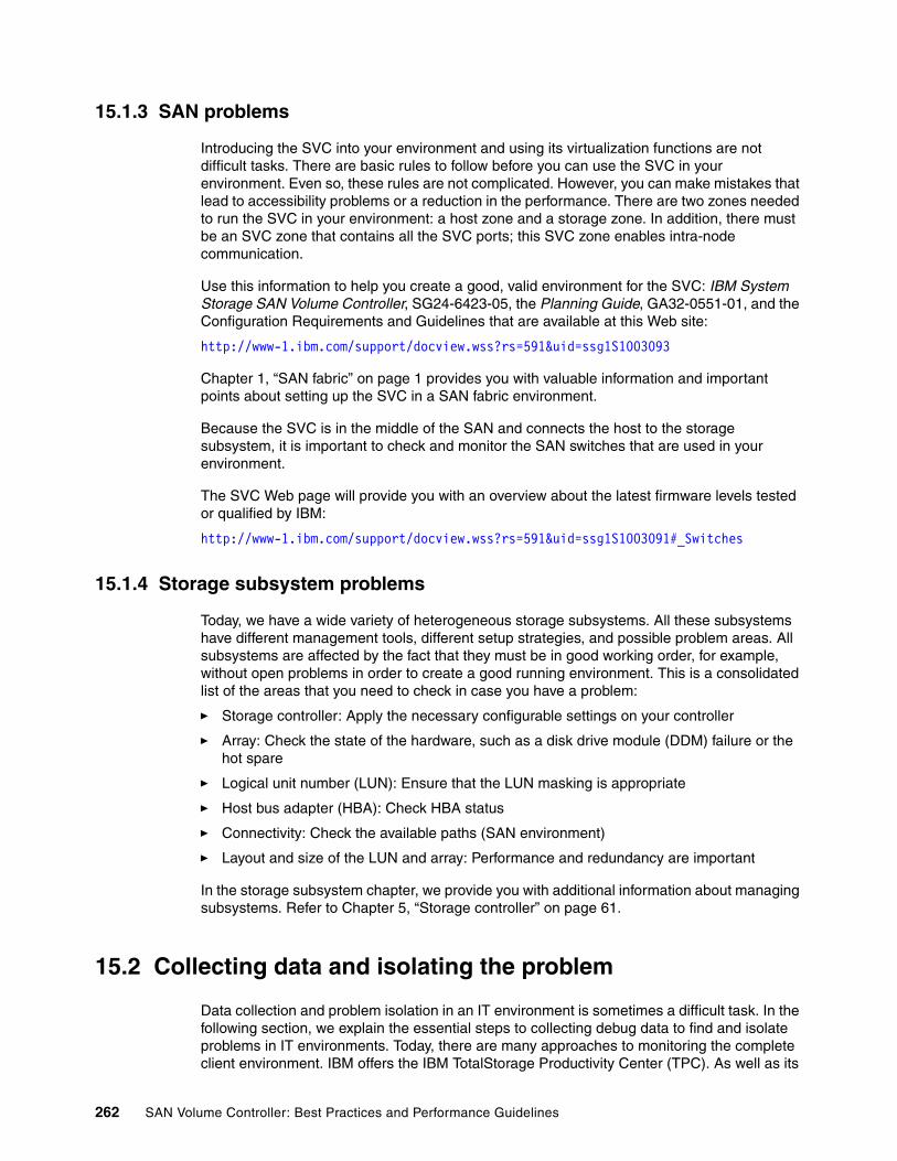
15.1.3 SAN problems
Introducing the SVC into your environment and using its virtualization functions are not difficult tasks. There are basic rules to follow before you can use the SVC in your environment. Even so, these rules are not complicated. However, you can make mistakes that lead to accessibility problems or a reduction in the performance. There are two zones needed to run the SVC in your environment: a host zone and a storage zone. In addition, there must be an SVC zone that contains all the SVC ports; this SVC zone enables intra-node communication.
Use this information to help you create a good, valid environment for the SVC: IBM System Storage SAN Volume Controller, SG24-6423-05, the Planning Guide, GA32-0551-01, and the Configuration Requirements and Guidelines that are available at this Web site:
http://www-1.ibm.com/support/docview.wss?rs=591&uid=ssg1S1003093
Chapter 1, “SAN fabric” on page 1 provides you with valuable information and important points about setting up the SVC in a SAN fabric environment.
Because the SVC is in the middle of the SAN and connects the host to the storage subsystem, it is important to check and monitor the SAN switches that are used in your environment.
The SVC Web page will provide you with an overview about the latest firmware levels tested or qualified by IBM:
http://www-1.ibm.com/support/docview.wss?rs=591&uid=ssg1S1003091#_Switches
15.1.4 Storage subsystem problems
Today, we have a wide variety of heterogeneous storage subsystems. All these subsystems have different management tools, different setup strategies, and possible problem areas. All subsystems are affected by the fact that they must be in good working order, for example, without open problems in order to create a good running environment. This is a consolidated list of the areas that you need to check in case you have a problem:
� Storage controller: Apply the necessary configurable settings on your controller
� Array: Check the state of the hardware, such as a disk drive module (DDM) failure or the hot spare
� Logical unit number (LUN): Ensure that the LUN masking is appropriate
� Host bus adapter (HBA): Check HBA status
� Connectivity: Check the available paths (SAN environment)
� Layout and size of the LUN and array: Performance and redundancy are important
In the storage subsystem chapter, we provide you with additional information about managing subsystems. Refer to Chapter 5, “Storage controller” on page 61.
15.2 Collecting data and isolating the problem
Data collection and problem isolation in an IT environment is sometimes a difficult task. In the following section, we explain the essential steps to collecting debug data to find and isolate problems in IT environments. Today, there are many approaches to monitoring the complete client environment. IBM offers the IBM TotalStorage Productivity Center (TPC). As well as its
262 SAN Volume Controller: Best Practices and Performance Guidelines
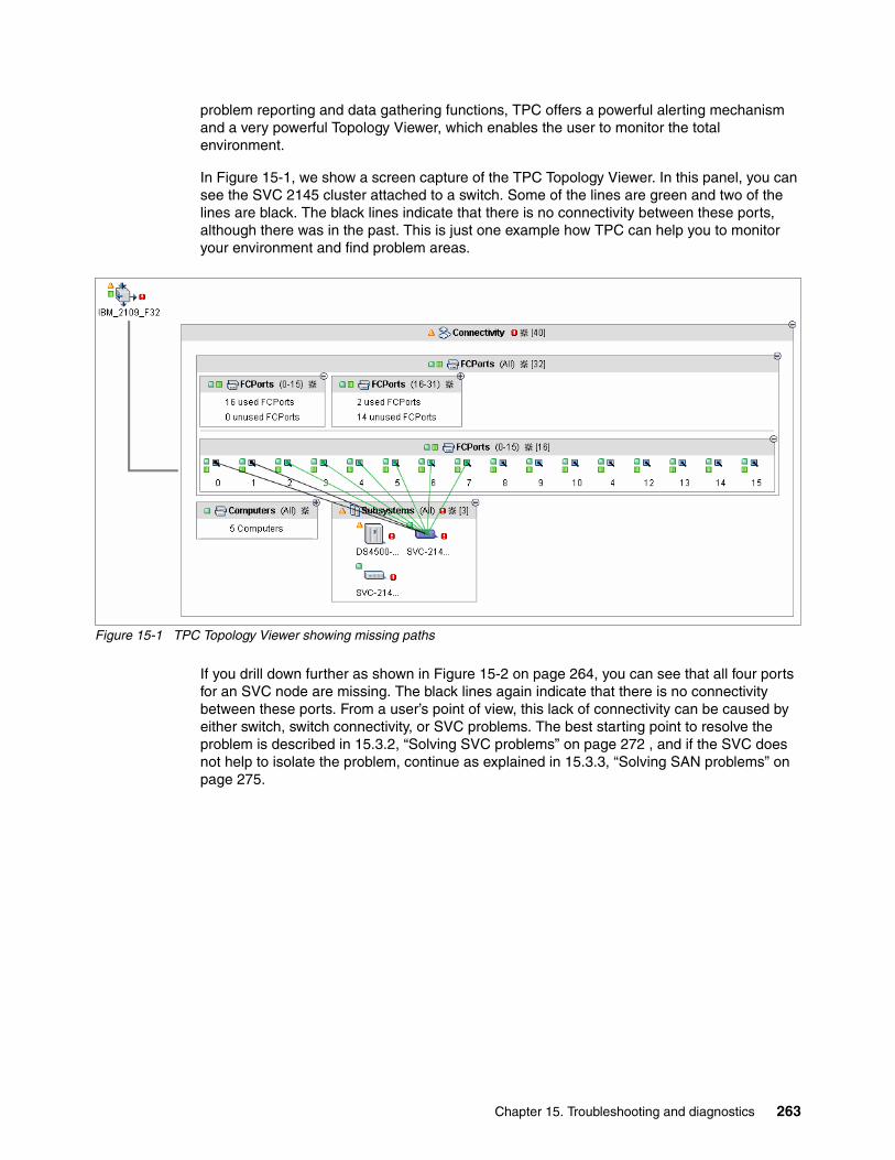
problem reporting and data gathering functions, TPC offers a powerful alerting mechanism and a very powerful Topology Viewer, which enables the user to monitor the total environment.
In Figure 15-1, we show a screen capture of the TPC Topology Viewer. In this panel, you can see the SVC 2145 cluster attached to a switch. Some of the lines are green and two of the lines are black. The black lines indicate that there is no connectivity between these ports, although there was in the past. This is just one example how TPC can help you to monitor your environment and find problem areas.
Figure 15-1 TPC Topology Viewer showing missing paths
If you drill down further as shown in Figure 15-2 on page 264, you can see that all four ports for an SVC node are missing. The black lines again indicate that there is no connectivity between these ports. From a user’s point of view, this lack of connectivity can be caused by either switch, switch connectivity, or SVC problems. The best starting point to resolve the problem is described in 15.3.2, “Solving SVC problems” on page 272 , and if the SVC does not help to isolate the problem, continue as explained in 15.3.3, “Solving SAN problems” on page 275.
Chapter 15. Troubleshooting and diagnostics 263
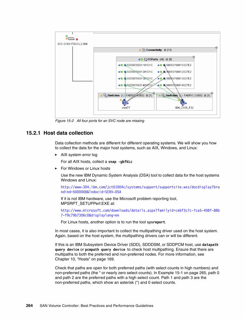
Figure 15-2 All four ports for an SVC node are missing
15.2.1 Host data collection
Data collection methods are different for different operating systems. We will show you how to collect the data for the major host systems, such as AIX, Windows, and Linux:
� AIX system error log
For all AIX hosts, collect a snap -gbfkLc
� For Windows or Linux hosts
Use the new IBM Dynamic System Analysis (DSA) tool to collect data for the host systems Windows and Linux:
http://www-304.ibm.com/jct01004c/systems/support/supportsite.wss/docdisplay?brandind=5000008&lndocid=SERV-DSA
If it is not IBM hardware, use the Microsoft problem reporting tool, MPSRPT_SETUPPerf.EXE at:
http://www.microsoft.com/downloads/details.aspx?familyid=cebf3c7c-7ca5-408f-88b7-f9c79b7306c0&displaylang=en
For Linux hosts, another option is to run the tool sysreport.
In most cases, it is also important to collect the multipathing driver used on the host system. Again, based on the host system, the multipathing drivers can or will be different.
If this is an IBM Subsystem Device Driver (SDD), SDDDSM, or SDDPCM host, use datapath query device or pcmpath query device to check host multipathing. Ensure that there are multipaths to both the preferred and non-preferred nodes. For more information, see Chapter 10, “Hosts” on page 169.
Check that paths are open for both preferred paths (with select counts in high numbers) and non-preferred paths (the * or nearly zero select counts). In Example 15-1 on page 265, path 0 and path 2 are the preferred paths with a high select count. Path 1 and path 3 are the non-preferred paths, which show an asterisk (*) and 0 select counts.
264 SAN Volume Controller: Best Practices and Performance Guidelines

Example 15-1 Checking paths
C:\Program Files\IBM\Subsystem Device Driver>datapath query device -l
Total Devices : 1
DEV#: 0 DEVICE NAME: Disk1 Part0 TYPE: 2145 POLICY: OPTIMIZEDSERIAL: 60050768018101BF2800000000000037LUN IDENTIFIER: 60050768018101BF2800000000000037============================================================================Path# Adapter/Hard Disk State Mode Select Errors 0 Scsi Port2 Bus0/Disk1 Part0 OPEN NORMAL 1752399 0 1 * Scsi Port3 Bus0/Disk1 Part0 OPEN NORMAL 0 0 2 Scsi Port3 Bus0/Disk1 Part0 OPEN NORMAL 1752371 0 3 * Scsi Port2 Bus0/Disk1 Part0 OPEN NORMAL 0 0
Collect the following information from the host:
� Operating system: Version and level� HBA: Driver firmware level� Multipathing driver level
15.2.2 Multipathing driver: SDD data
IBM Subsystem Device Driver (SDD) has been enhanced to collect SDD trace data periodically and write the trace data to the system’s local hard drive. SDD maintains four files for its trace data:
� sdd.log� sdd_bak.log� sddsrv.log� sddsrv_bak.log
The necessary data for debugging problems is collected by running sddgetdata. If this command is not found, collect the following files.
These files can be found in the following directories:
� AIX - /var/adm/ras
� Hewlett-Packard UNIX - /var/adm
� Linux - /var/log
� Solaris - /var/adm
� Windows 2000 Server and Windows NT Server - \WINNT\system32
� Windows Server 2003 - \Windows\system32
SDDPCMSDDPCM has been enhanced to collect SDDPCM trace data periodically and write the trace data to the system’s local hard drive. SDDPCM maintains four files for its trace data:
� pcm.log� pcm_bak.log� pcmsrv.log� pcmsrv_bak.log
Chapter 15. Troubleshooting and diagnostics 265

Starting with SDDPCM 2.1.0.8, the relevant data for debugging problems is collected by running sddpcmgetdata. If this command is not found, collect the following files.
These files can be found in the /var/adm/ras directory.
� pcm.log
� pcm_bak.log
� pcmsrv.log
� pcmsrv_bak.log
� The output of the pcmpath query adapter command
� The output of the pcmpath query device command
SDDPCM provides the sddpcmgetdata script to collect information used for problem determination. The sddpcmgetdata script creates a tar file at the current directory with the current date and time as a part of the file name. For example: sddpcmdata_hostname_yyyymmdd_hhmmss.tar
The variable yyyymmdd_hhmmss is the time stamp of the file creation. When you report an SDDPCM problem, it is essential to run this script and send this tar file for problem determination. See Example 15-2.
Example 15-2 Use of the sddpcmgetdata script
/tmp/sddpcmgetdata>sddpcmgetdata/tmp/sddpcmgetdata>ls ./../ sddpcmdata_test1_20070806_122521.tar
SDDDSMSDDDSM also provides the sddgetdata script to collect information to use for problem determination. SDDGETDATA.BAT is the batch file that generates the following files:
� sddgetdata_%host%_%date%_%time%.cab
� SDD\SDDSrv logs
� Datapath output
� Event logs
� Cluster log
� SDD specific registry entry
� HBA information
Data collection scriptIn Example 15-3 on page 267, we provide a script that collects all the necessary data for an AIX host at one time. You can execute the script in Example 15-3 on page 267 by using these steps:
1. vi /tmp/datacollect.sh
2. Cut and paste the script into the /tmp/datacollect.sh file and save the file.
3. chmod 755 /tmp/datacollect.sh
4. /tmp/datacollect.sh
266 SAN Volume Controller: Best Practices and Performance Guidelines
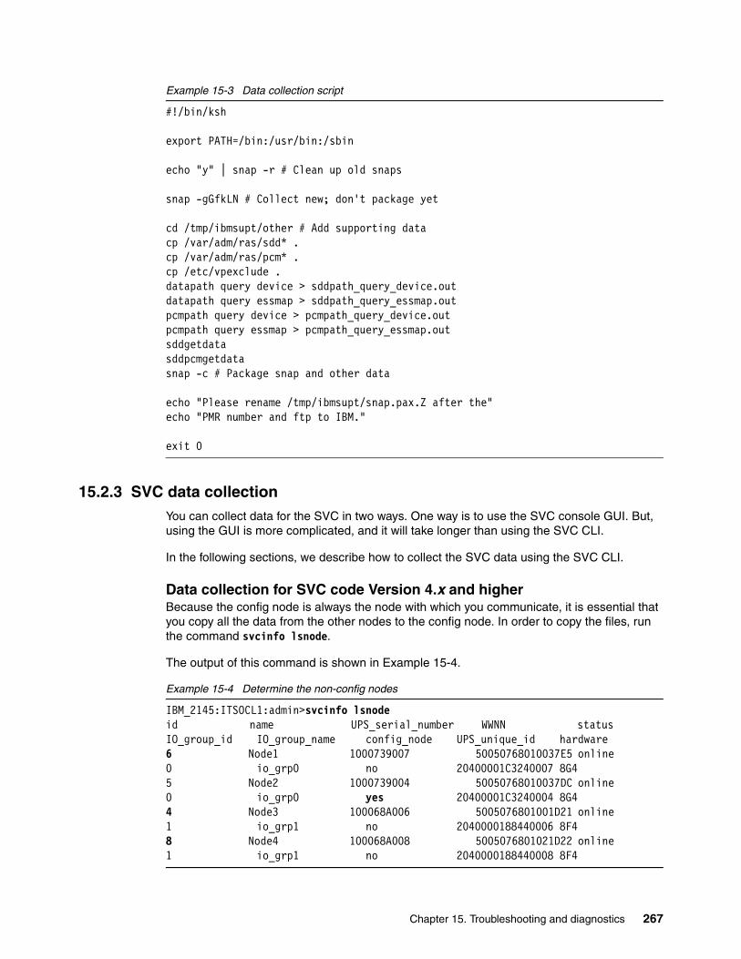
Example 15-3 Data collection script
#!/bin/ksh
export PATH=/bin:/usr/bin:/sbin
echo "y" | snap -r # Clean up old snaps
snap -gGfkLN # Collect new; don't package yet
cd /tmp/ibmsupt/other # Add supporting datacp /var/adm/ras/sdd* .cp /var/adm/ras/pcm* .cp /etc/vpexclude .datapath query device > sddpath_query_device.outdatapath query essmap > sddpath_query_essmap.outpcmpath query device > pcmpath_query_device.outpcmpath query essmap > pcmpath_query_essmap.outsddgetdatasddpcmgetdatasnap -c # Package snap and other data
echo "Please rename /tmp/ibmsupt/snap.pax.Z after the"echo "PMR number and ftp to IBM."
exit 0
15.2.3 SVC data collectionYou can collect data for the SVC in two ways. One way is to use the SVC console GUI. But, using the GUI is more complicated, and it will take longer than using the SVC CLI.
In the following sections, we describe how to collect the SVC data using the SVC CLI.
Data collection for SVC code Version 4.x and higherBecause the config node is always the node with which you communicate, it is essential that you copy all the data from the other nodes to the config node. In order to copy the files, run the command svcinfo lsnode.
The output of this command is shown in Example 15-4.
Example 15-4 Determine the non-config nodes
IBM_2145:ITSOCL1:admin>svcinfo lsnodeid name UPS_serial_number WWNN status IO_group_id IO_group_name config_node UPS_unique_id hardware6 Node1 1000739007 50050768010037E5 online 0 io_grp0 no 20400001C3240007 8G45 Node2 1000739004 50050768010037DC online 0 io_grp0 yes 20400001C3240004 8G44 Node3 100068A006 5005076801001D21 online 1 io_grp1 no 2040000188440006 8F48 Node4 100068A008 5005076801021D22 online 1 io_grp1 no 2040000188440008 8F4
Chapter 15. Troubleshooting and diagnostics 267
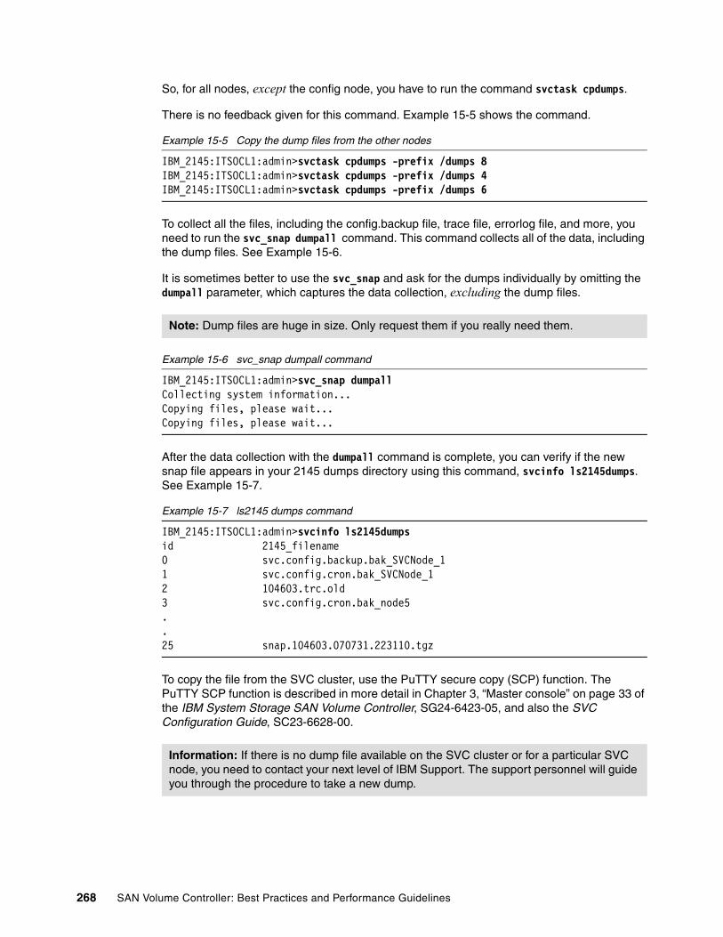
So, for all nodes, except the config node, you have to run the command svctask cpdumps.
There is no feedback given for this command. Example 15-5 shows the command.
Example 15-5 Copy the dump files from the other nodes
IBM_2145:ITSOCL1:admin>svctask cpdumps -prefix /dumps 8IBM_2145:ITSOCL1:admin>svctask cpdumps -prefix /dumps 4IBM_2145:ITSOCL1:admin>svctask cpdumps -prefix /dumps 6
To collect all the files, including the config.backup file, trace file, errorlog file, and more, you need to run the svc_snap dumpall command. This command collects all of the data, including the dump files. See Example 15-6.
It is sometimes better to use the svc_snap and ask for the dumps individually by omitting the dumpall parameter, which captures the data collection, excluding the dump files.
Example 15-6 svc_snap dumpall command
IBM_2145:ITSOCL1:admin>svc_snap dumpallCollecting system information...Copying files, please wait...Copying files, please wait...
After the data collection with the dumpall command is complete, you can verify if the new snap file appears in your 2145 dumps directory using this command, svcinfo ls2145dumps. See Example 15-7.
Example 15-7 ls2145 dumps command
IBM_2145:ITSOCL1:admin>svcinfo ls2145dumpsid 2145_filename0 svc.config.backup.bak_SVCNode_11 svc.config.cron.bak_SVCNode_12 104603.trc.old3 svc.config.cron.bak_node5..25 snap.104603.070731.223110.tgz
To copy the file from the SVC cluster, use the PuTTY secure copy (SCP) function. The PuTTY SCP function is described in more detail in Chapter 3, “Master console” on page 33 of the IBM System Storage SAN Volume Controller, SG24-6423-05, and also the SVC Configuration Guide, SC23-6628-00.
Note: Dump files are huge in size. Only request them if you really need them.
Information: If there is no dump file available on the SVC cluster or for a particular SVC node, you need to contact your next level of IBM Support. The support personnel will guide you through the procedure to take a new dump.
268 SAN Volume Controller: Best Practices and Performance Guidelines

15.2.4 SAN data collection
In this section, we discuss capturing and collecting the switch support data. If there are problems that cannot be fixed by a simple maintenance task, such as exchanging hardware, IBM technical support will ask you for the data collection.
We list how to collect the switch support data for Brocade, McDATA, and Cisco.
Brocade switchesFor most of the current Brocade switches, you need to issue the supportSave command to collect the support data.
McDATAUsing the Enterprise Fabric Connectivity Manager (EFCM) is the preferred way of collecting data for McDATA switches.
For EFCM 8.7 and higher levels (without the group manager license), select the switch for which you want to collect data, right-click on it, and launch the Element Manager. See Figure 15-3.
On the Element Manager panel, choose Maintenance → Data collection → Extended, and save the zip file on the local disk.
Figure 15-3 Data collection for McDATA
CiscoTelnet to the switch and collect the output from the following commands: terminal length 0, show tech-support detail, and terminal length 24.
15.2.5 Storage subsystem data collection
How you collect the data depends on the subsystem storage. We only show how to collect the support data for IBM System Storage.
Chapter 15. Troubleshooting and diagnostics 269

DS4000With Storage Manager levels higher than 9.1, there is a feature called Collect All Support Data. To collect the information, open the Storage Manager and select Advanced → Troubleshooting → Collect All Support Data.
DS8000 and DS6000By issuing the following series of commands, you get an overview about the current configuration information of the DS8000 or DS6000:
1. lsfbvol
2. lshostconnect
3. lsarray
4. lsrank
5. lsioports
6. lsvolgrp
The complete data collection instead will normally be done by the IBM service support representative (IBM SSR) or the IBM Support center. The IBM product engineering (PE) package includes all current configuration data as well as diagnostic data.
15.3 Recovering from problems
In this section, we provide guidance about how to recover from several of the more common problems that you might encounter. We also show several example problems and how to fix them. In all cases, it is essential to read and understand the current limitations, to verify the configuration, and to determine if you need to install the latest flashes.
The following page links to an overview about all IBM products:
http://www-304.ibm.com/jct01004c/systems/support/supportsite.wss/allproducts?brandind=5345868
To review the SVC Web page for the latest flashes relating to the concurrent code upgrades, code levels, and matrixes:
http://www-304.ibm.com/jct01004c/systems/support/supportsite.wss/supportresources?brandind=5000033&familyind=5329743&taskind=1
15.3.1 Solving host problems
Apart from hardware-related problems, there can be problems in areas such as the operating system or the software used on the host. These problems are normally handled by the host administrator or the service provider of the host system.
However, the multipathing driver installed on the host and its features can help to determine possible problems. In Example 15-8 on page 271, we show a missing path reported by the SDD output on the host by using the datapath query device -l command. This missing path can be caused by hardware or software problems.
Hardware problems, such as:
� Faulty small form-factor pluggable transceiver (SFP) in host or switch� Faulty fiber optic cable
270 SAN Volume Controller: Best Practices and Performance Guidelines
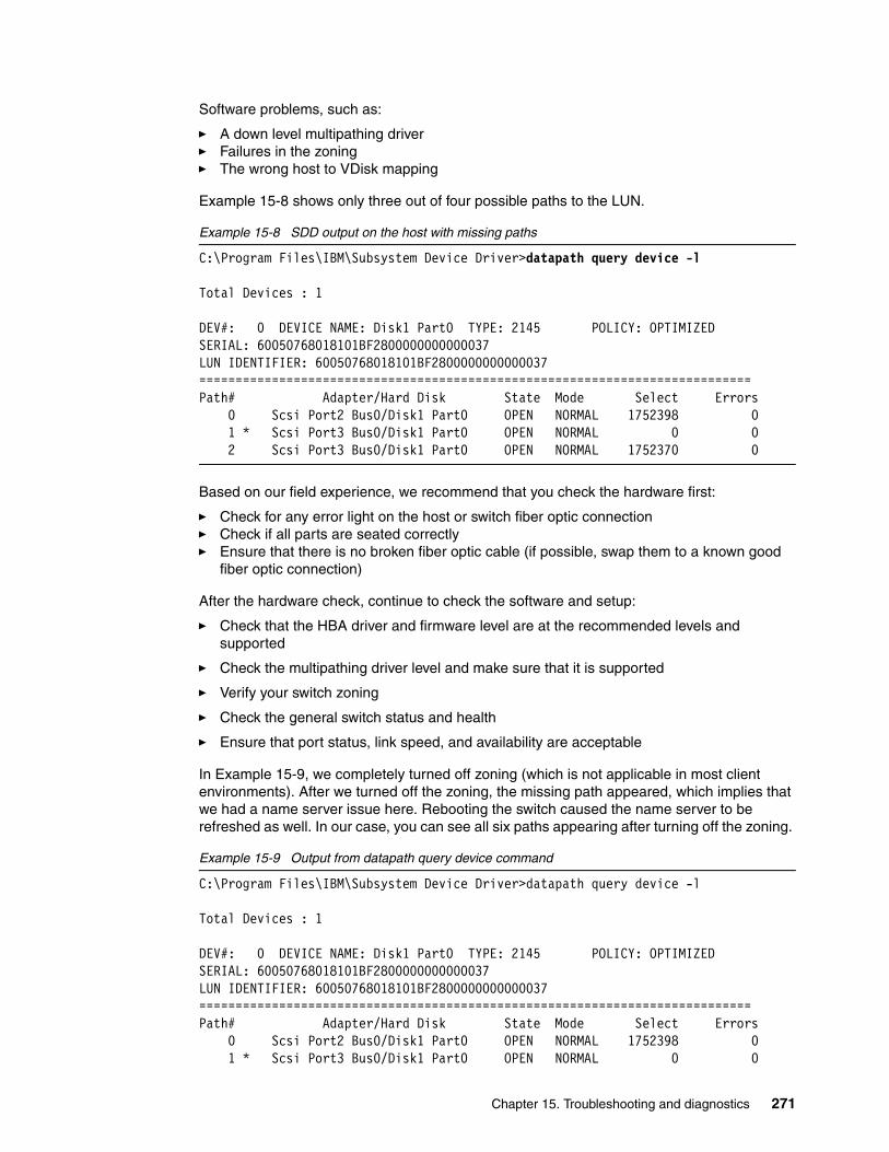
Software problems, such as:
� A down level multipathing driver� Failures in the zoning� The wrong host to VDisk mapping
Example 15-8 shows only three out of four possible paths to the LUN.
Example 15-8 SDD output on the host with missing paths
C:\Program Files\IBM\Subsystem Device Driver>datapath query device -l
Total Devices : 1
DEV#: 0 DEVICE NAME: Disk1 Part0 TYPE: 2145 POLICY: OPTIMIZEDSERIAL: 60050768018101BF2800000000000037LUN IDENTIFIER: 60050768018101BF2800000000000037============================================================================Path# Adapter/Hard Disk State Mode Select Errors 0 Scsi Port2 Bus0/Disk1 Part0 OPEN NORMAL 1752398 0 1 * Scsi Port3 Bus0/Disk1 Part0 OPEN NORMAL 0 0 2 Scsi Port3 Bus0/Disk1 Part0 OPEN NORMAL 1752370 0
Based on our field experience, we recommend that you check the hardware first:
� Check for any error light on the host or switch fiber optic connection� Check if all parts are seated correctly� Ensure that there is no broken fiber optic cable (if possible, swap them to a known good
fiber optic connection)
After the hardware check, continue to check the software and setup:
� Check that the HBA driver and firmware level are at the recommended levels and supported
� Check the multipathing driver level and make sure that it is supported
� Verify your switch zoning
� Check the general switch status and health
� Ensure that port status, link speed, and availability are acceptable
In Example 15-9, we completely turned off zoning (which is not applicable in most client environments). After we turned off the zoning, the missing path appeared, which implies that we had a name server issue here. Rebooting the switch caused the name server to be refreshed as well. In our case, you can see all six paths appearing after turning off the zoning.
Example 15-9 Output from datapath query device command
C:\Program Files\IBM\Subsystem Device Driver>datapath query device -l
Total Devices : 1
DEV#: 0 DEVICE NAME: Disk1 Part0 TYPE: 2145 POLICY: OPTIMIZEDSERIAL: 60050768018101BF2800000000000037LUN IDENTIFIER: 60050768018101BF2800000000000037============================================================================Path# Adapter/Hard Disk State Mode Select Errors 0 Scsi Port2 Bus0/Disk1 Part0 OPEN NORMAL 1752398 0 1 * Scsi Port3 Bus0/Disk1 Part0 OPEN NORMAL 0 0
Chapter 15. Troubleshooting and diagnostics 271

2 Scsi Port3 Bus0/Disk1 Part0 OPEN NORMAL 1752370 0 3 * Scsi Port2 Bus0/Disk1 Part0 OPEN NORMAL 0 0 4 * Scsi Port2 Bus0/Disk1 Part0 OPEN NORMAL 0 0 5 Scsi Port2 Bus0/Disk1 Part0 OPEN NORMAL 0 0
C:\Program Files\IBM\Subsystem Device Driver>datapath query device -l
Total Devices : 1
DEV#: 0 DEVICE NAME: Disk1 Part0 TYPE: 2145 POLICY: OPTIMIZEDSERIAL: 60050768018101BF2800000000000037LUN IDENTIFIER: 60050768018101BF2800000000000037============================================================================Path# Adapter/Hard Disk State Mode Select Errors 0 Scsi Port2 Bus0/Disk1 Part0 OPEN NORMAL 1752399 0 1 * Scsi Port3 Bus0/Disk1 Part0 OPEN NORMAL 0 0 2 Scsi Port3 Bus0/Disk1 Part0 OPEN NORMAL 1752371 0 3 * Scsi Port2 Bus0/Disk1 Part0 OPEN NORMAL 0 0 4 * Scsi Port2 Bus0/Disk1 Part0 CLOSE OFFLINE 0 0 5 Scsi Port2 Bus0/Disk1 Part0 CLOSE OFFLINE 0 0
C:\Program Files\IBM\Subsystem Device Driver>datapath query device -l
Total Devices : 1
After re-enabling the zoning, we got our four paths, and the two remaining paths are CLOSE OFFLINE.
15.3.2 Solving SVC problems
For any problem in an environment running the SVC, we advise you to use the Run Maintenance Procedure as shown in Figure 15-4 first before trying to fix the problem anywhere else.
The maintenance procedure checks the error condition again, and if it was a temporary failure, it marks this problem as fixed; otherwise, the problem persists. In this case, the SVC will guide you through several verification steps to help you find the problem area.
Figure 15-4 Run Maintenance Procedures on the SVC
The SVC error log provides you with information, such as all of the events on the SVC, all of the error messages, and SVC warning information. Although you can mark the error as fixed in the error log, we recommend that you always use the Run Maintenance Procedure as shown in Figure 15-4.
Starting with SVC code Version 4.2, the error log has a new feature called Sense Expert as shown in Figure 15-5 on page 273. This tool translates the sense data to something more meaningful.
272 SAN Volume Controller: Best Practices and Performance Guidelines

Figure 15-5 Sense Expert
Another common practice is to use the SVC CLI to find problems. The following is a list of commands providing you with a set of information to get a status of your current environment:
� svctask detectmdisk (discover the changes in the back end)
� svcinfo lscluster clustername (check the cluster status)
� svcinfo lsnode nodeid (check the node and port status)
� svcinfo lscontroller controllerid (check the controller status)
� svcinfo lsmdisk (these commands will give you overall status of all the controllers and MDisks)
� svcinfo lsmdiskgrp (these commands will give you the overall status of all Managed Disk Groups (MDGs))
� svcinfo lsvdisk (are they all online now?)
If the problem is caused by the SVC and you are unable to fix it either with the Run Maintenance Procedure or with the error log, you need to collect the SVC debug data as explained in 15.2.3, “SVC data collection” on page 267.
If the problem is related to anything outside of the SVC, refer to the appropriate section in this guide to find and fix the problem.
Cluster upgrade checksThere are a number of prerequisite checks to perform to confirm readiness prior to performing SVC concurrent code load:
Important: Although the SVC raises error messages, most problems are not caused by the SVC. Most problems are introduced by the storage subsystems or the SAN.
Chapter 15. Troubleshooting and diagnostics 273
� Check the back-end storage configurations for SCSI ID to LUN ID mappings. Normally, a 1625 error is detected if there is a problem, but it is also worthwhile to manually check these.
Specifically, we need to make sure that the SCSI ID to LUN ID is the same for each node. Each WWPN of the SVC has the identical LUN mapping for every node. For example, LUN 1 is the same as ESS/2107/etc serial number for every WWPN of the SVC cluster.
You can use these commands on the ESS to pull the data out to check ESS mapping:
esscli list port -d "ess=<ESS name>" esscli list hostconnection -d "ess=<ESS name>" esscli list volumeaccess -d "ess=<ESS name>"
And, verify that the mapping is identical.
Use the following commands for a DS8000 to check the SCSI ID to LUN ID mappings:
lsioport -dev <DS8K name> -l -fullid lshostconnect -dev <DS8K name> -l showvolgrp -lunmap <DS8K name> lsfbvol -dev <DS8K name> -l -vol <SVC Vol Groups>
LUN mapping problems are not likely on a DS8000 based on the way that the volume groups are allocated; however, it is still worthwhile verifying the configuration just prior to upgrades.
For the DS4000, we also recommend that you verify that each WWPN of the SVC has the identical LUN mapping for every node.
Open Storage Management for DS4000 and use the Mappings View to verify the mapping. You can also run the data collection for the DS4000 and use the subsystem profile to check the mapping.
� For storage subsystems from other vendors, use the corresponding steps to verify the correct mapping.
Use the host multipathing commands, such as the datapath query device and svcinfo lsvdisk, mdisk, and lscontroller commands to verify:
– Host path redundancy
– Controller redundancy
– Controller misconfigurations
– Use the “Run Maintenance Procedure” or “Analyze Error Log” function in the SVC console GUI to investigate any unfixed or investigated SVC errors.
– Download and execute the SAN Volume Controller Software Upgrade Test Utility:
http://www-1.ibm.com/support/docview.wss?uid=ssg1S4000585
– Review the latest flashes, hints, and tips prior to the cluster upgrade. There will be a list of flashes, hints, and tips on the SVC code download page that are directly applicable. Also, review the latest updates shown here:
http://www-1.ibm.com/support/docview.wss?rs=591&uid=ssg1S1002860
Note: In most cases, the SVC is not the cause of the problem, but it can certainly help to isolate the root cause of the problem.
274 SAN Volume Controller: Best Practices and Performance Guidelines
15.3.3 Solving SAN problems
Problems in the SAN on the SAN switches can be caused by a huge variety of things. Those problems can be related to either a hardware fault or to a software problem on the switch. Hardware defects are normally easier to find. Here is a short list about the possible hardware failures:
� Switch power, fan, or cooling� Application-specific integrated circuit (ASIC) � Installed SFP� Fiber optic cables
Software failures are more difficult to analyze, and in most cases, you need the data collection and you need to involve IBM technical support. But before taking any other step, we recommend that you check the installed code level for any known problems. We also recommend that you check if there is a new code level available that resolves the problem that you are experiencing. Use the following Web link for more information:
http://www-304.ibm.com/jct01004c/systems/support/supportsite.wss/allproducts?brandind=5345868
If you are unable to fix the problem with these actions, use 15.2.4, “SAN data collection” on page 269, collect the SAN switch debugging data, and then call IBM technical support.
15.3.4 Typical SVC storage problems
SVC is a great tool to find and analyze back-end storage subsystem problems, because the SVC has a monitoring and logging mechanism.
However, the SVC is not as helpful in finding problems from a host perspective. The reason is that the SVC is a SCSI target for the host, and the SCSI protocol defines that errors are reported via the host.
Typical problems for subsystem controllers are incorrect configuration, which results in a 1625 error code. Other problems related to the storage subsystem are failures pointing to the managed disk I/O error 1310, disk media error 1320, and error recovery procedure 1370.
Other failure codes are more related to the SAN environment, such as error 1060 Fibre Channel ports are not operational and error 1220 A remote port is excluded.
However, all messages do not have just one explicit reason for being issued. Therefore, you have to check multiple areas and not just the SAN and subsystem storage.
Although the latest SVC code level is supported to run on older HBAs, storage subsystem drivers, and code levels, we recommend that you use the latest tested levels. Use the following link for further information:
http://www-304.ibm.com/jct01004c/systems/support/supportsite.wss/supportresources?taskind=3&brandind=5000033&familyind=5329743
You can refer to Chapter 13, “Maintenance” on page 237 for additional information.
Next, we discuss two examples of a misconfigured SVC environment:
� Configuration problems in the SAN, such as choosing the wrong port. For example, four SVC nodes need to be zoned to one HBA. But, this example shows that there are two ports zoned belonging to the same node. The result is that the host and its multipathing driver will not see all of the necessary paths. Incorrect zoning is shown in Example 15-10.
Chapter 15. Troubleshooting and diagnostics 275

Example 15-10 Wrong WWPN zoning
zone: H_SENEGAL_CL1 21:00:00:e0:8b:89:b9:c0 50:05:07:68:01:40:1d:21 50:05:07:68:01:30:1d:21 50:05:07:68:01:40:37:e5 50:05:07:68:01:30:37:dc
The correct zoning needs to look like the zoning shown in Example 15-11.
Example 15-11 Correct WWPN zoning
zone: H_SENEGAL_CL1 21:00:00:e0:8b:89:b9:c0 50:05:07:68:01:40:1d:21 50:05:07:68:01:32:1d:22 50:05:07:68:01:40:37:e5 50:05:07:68:01:30:37:dc
� Example 15-12 shows an unequal LUN distribution on the back-end storage controller. Note that one WWPN has zero path count, while the other WWPN carries all the paths of both LUNs. This situation has two possible causes:
– If the back end is a controller with a preferred controller, perhaps the LUNs are both allocated to the same controller. This is likely with the DS4000 and can be fixed by redistributing the LUNs evenly on the DS4000 and then rediscovering the LUNs on the SVC.
– Another possible cause is that the WWPN with zero count is not visible to all the SVC nodes via the SAN zoning. Use svcinfo lsfabric 0 to confirm.
Example 15-12 Unequal LUN distribution on the back-end controller
IBM_2145:ITSOCL1:admin>svcinfo lscontroller 0id 0controller_name controller0WWNN 200400A0B8174431mdisk_link_count 2max_mdisk_link_count 4degraded novendor_id IBMproduct_id_low 1742-900product_id_highproduct_revision 0520ctrl_s/nWWPN 200400A0B8174433path_count 0max_path_count 4WWPN 200500A0B8174433path_count 8max_path_count 8
IBM_2145:ITSOCL1:admin>svctask detectmdisk
IBM_2145:ITSOCL1:admin>svcinfo lscontroller 0id 0controller_name controller0
276 SAN Volume Controller: Best Practices and Performance Guidelines

WWNN 200400A0B8174431mdisk_link_count 2max_mdisk_link_count 4degraded novendor_id IBMproduct_id_low 1742-900product_id_highproduct_revision 0520ctrl_s/nWWPN 200400A0B8174433path_count 4max_path_count 4WWPN 200500A0B8174433path_count 4max_path_count 8
UpgradabilityCheck the following Web site to see from which level to which level the SVC code can be upgraded. Furthermore, check which level of SVC console GUI is required to run the latest SVC code:
http://www-304.ibm.com/jct01004c/systems/support/supportsite.wss/supportresources?taskind=2&brandind=5000033&familyind=5329743
Upgrade orderThe following list shows a desirable upgrade order:
1. SVC Master Console GUI2. SVC cluster code3. SAN switches4. Host system (HBA, OS and service packs, and multipathing driver)
Upgrade the SVC cluster in a Metro or Global Mirror cluster relationshipWhen upgrading the SVC cluster software where the cluster participates in an intercluster relationship, make sure to only upgrade one cluster at a time. Do not attempt to upgrade both SVC clusters concurrently. This is not policed by the software upgrade process. Allow the software upgrade to complete on one cluster before you start the upgrade on the other cluster.
If both clusters are upgraded concurrently, it might lead to a loss of synchronization. In stress situations, it might lead to a loss of availability.
15.3.5 Solving storage subsystem problems
These are some of the common storage subsystem problems.
Determining the correct amount of pathsUsing svcinfo commands, it is possible to find out the total amount of paths that you can see. To determine the actual value of the available paths, you need to use the following formula:
Number of MDisks x Number of SVC nodes per Cluster = Number of pathsmdisk_link_count x Number of SVC nodes per Cluster = Sum of path_count
Chapter 15. Troubleshooting and diagnostics 277

In this example:
2 x 4 = 8
Example 15-13 shows how to obtain this information using the commands svcinfo lscontroller id and svcinfo lsnode.
Example 15-13 svcinfo lscontroller 0 command
IBM_2145:ITSOCL1:admin>svcinfo lscontroller 0id 0controller_name controller0WWNN 200400A0B8174431mdisk_link_count 2max_mdisk_link_count 4degraded novendor_id IBMproduct_id_low 1742-900product_id_highproduct_revision 0520ctrl_s/nWWPN 200400A0B8174433path_count 4max_path_count 12WWPN 200500A0B8174433path_count 4max_path_count 8
IBM_2145:ITSOCL1:admin>svcinfo lsnodeid name UPS_serial_number WWNN status IO_group_id IO_group_name config_node UPS_unique_id hardware6 Node1 1000739007 50050768010037E5 online 0 io_grp0 no 20400001C3240007 8G45 Node2 1000739004 50050768010037DC online 0 io_grp0 yes 20400001C3240004 8G44 Node3 100068A006 5005076801001D21 online 1 io_grp1 no 2040000188440006 8F48 Node4 100068A008 5005076801021D22 online 1 io_grp1 no 2040000188440008 8F4
Fixing subsystem problems in an SVC-attached environmentNext, we explain how to determine the root cause of the problem and in what order to start checking:
1. Run the maintenance procedures under SVC.
2. Check the attached storage subsystem for misconfigurations or failures.
3. Check the SAN for switch problems or zoning failures.
4. Collect all support data and involve IBM support.
Now, we look at these steps sequentially:
1. Run the maintenance procedures under SVC.
278 SAN Volume Controller: Best Practices and Performance Guidelines

To run the SVC Maintenance Procedures, open the SVC console GUI. Select Service and Maintenance → Run Maintenance Procedures. On the panel that appears on the left side, click Start Analysis.
Figure 15-6 Start Analysis from the SVC console GUI
For more information about how to use the SVC Maintenance Procedures, refer to IBM System Storage SAN Volume Controller, SG24-6423-05, or the SVC Service Guide, GC26-7901-01.
2. Check the attached storage subsystem for misconfigurations or failures:
a. Independent of the type of storage subsystem, the first thing to check is if there are any open problems on the system. Use the service or maintenance features provided with the storage subsystem to fix these problems. If needed, call support.
b. Then, check if the LUN masking is correct. When attached to the SVC, you have to make sure that the LUN masking maps to the active zone set on the switch. Create a LUN mask for each HBA port that is zoned to the SVC. If you fail to do so, the SVC will raise error messages. For more information, read the SVC configuration requirements and guidelines:
http://www-304.ibm.com/jct01004c/systems/support/supportsite.wss/supportresources?taskind=3&brandind=5000033&familyind=5329743
c. Check if you have established a good LUN allocation on your storage subsystem and that the LUNs are equally distributed on all zoned subsystem controllers.
Next, we show an example of a misconfigured storage subsystem, and how this misconfigured storage system will appear in the SVC. Furthermore, we explain how to fix that problem.
By running the svcinfo lscontroller ID command, you will get the output shown in Example 15-14. As highlighted in the example, the MDisks, and therefore, the LUNs, are not equally allocated. In our example, the LUNs provided by the storage subsystem are only visible by one path (WWPN).
Example 15-14 MDisks unevenly distributed
IBM_2145:ITSOCL1:admin>svcinfo lscontroller 0id 0controller_name controller0WWNN 200400A0B8174431mdisk_link_count 2max_mdisk_link_count 4degraded novendor_id IBMproduct_id_low 1742-900product_id_highproduct_revision 0520ctrl_s/nWWPN 200400A0B8174433path_count 8max_path_count 12
Chapter 15. Troubleshooting and diagnostics 279

WWPN 200500A0B8174433path_count 0max_path_count 8
d. To determine the root cause of this problem, follow the actions described in “Fixing subsystem problems in an SVC-attached environment” on page 278. If running the Maintenance procedure under SVC does not fix the problem, continue with the second step checking the storage subsystem for failures or misconfigurations.
If you are unsure about which of the attached MDisks has which corresponding LUN ID, use this command svcinfo lsmdisk (see Example 15-15).
Example 15-15 Determine the UID for the MDisk
IBM_2145:ITSOCL1:admin>svcinfo lsmdiskid name status mode mdisk_grp_id mdisk_grp_name capacity ctrl_LUN_# controller_name UID0 mdisk0 online managed 0 MDG-1 600.0GB 0000000000000000 controller0 600a0b800017423300000059469cf845000000000000000000000000000000002 mdisk2 online managed 0 MDG-1 70.9GB 0000000000000002 controller0 600a0b800017443100000096469cf0e800000000000000000000000000000000
e. With the MDisk and the UID, you can determine which LUN is attached to the SVC. Then, check if the LUNs are equally distributed on the available storage controllers. If not, redistribute them equally over all available storage controllers.
f. Run the svcinfo lscontroller ID again to check if this action resolved the problem.
Example 15-16 Equally distributed MDisk on all available paths
IBM_2145:ITSOCL1:admin>svcinfo lscontroller 0id 0controller_name controller0WWNN 200400A0B8174431mdisk_link_count 2max_mdisk_link_count 4degraded novendor_id IBMproduct_id_low 1742-900product_id_highproduct_revision 0520ctrl_s/nWWPN 200400A0B8174433path_count 4max_path_count 12WWPN 200500A0B8174433path_count 4max_path_count 8
g. In our example, the problem was solved by changing the LUN allocation. If step 2 did not solve the problem, you need to continue with step 3.
3. Check the SAN for switch problems or zoning failures.
Problems in the SAN can be caused by a great variety of things. See 15.2.4, “SAN data collection” on page 269 for more information.
280 SAN Volume Controller: Best Practices and Performance Guidelines

4. Collect all support data and involve IBM support.
Collect the support data for the involved SAN, SVC, or storage systems as described in 15.2, “Collecting data and isolating the problem” on page 262.
15.3.6 Common error recovery steps
In this section, we describe how to use the PuTTY CLI to carry out common error recovery steps of back-end SAN or storage problems.
These steps are done by the maintenance procedures, but it is sometimes quicker to run these commands directly via the CLI. Run these commands anytime that you have:
� Logically distributed the paths on the DS4000
� A known back-end storage issue (for example, error 1370 or error 1630)
� Performed maintenance
It is especially important to run these commands when there is a back-end storage configuration or zoning change to ensure the SVC follows the changes.
The PuTTY commands for common error recovery are:
� svctask detectmdisk (discover the changes in the back end)
� svcinfo lscontroller and svcinfo lsmdisk (these commands will give you overall status of all the controllers and MDisks)
� svcinfo lscontroller controllerid (check the controller that was causing the problems and verify all the WWPNs are listed as you expect)
� svctask includemdisk mdiskid (for each degraded or offline MDisk)
� svcinfo lsmdisk (are they all online now?)
� svcinfo lscontroller controllerid (check that the path_counts are distributed somewhat evenly across the WWPNs)
Finally, run the maintenance procedures on the SVC to fix every error.
15.4 Livedump
SVC livedump is a procedure that IBM Support might ask clients to run by IBM Support. Only invoke livedump under the direction of IBM Support.
Sometimes, investigations require a livedump from the configuration node in the cluster. A livedump is a lightweight dump from a node, which can be taken without impacting host I/O. The only impact is a slight reduction in system performance (due to reduced memory being available for the I/O cache) until the dump is finished. The instructions for a livedump are:
1. Prepare the node for taking a livedump: svctask preplivedump <node id/name>
This will reserve the necessary system resources to take a livedump. The operation can take some time, because the node might have to flush some data from the cache. System performance might be slightly affected after running this command, because some memory, which normally is available to the cache, is not available while the node is prepared for a livedump.
Chapter 15. Troubleshooting and diagnostics 281

After the command has completed, then the livedump is ready to be triggered. This can be seen looking at the output from svcinfo lslivedump <node id/name>.
The status must be reported as “prepared”.
2. Trigger the livedump: svctask triggerlivedump <node id/name>
This command will complete as soon as the data capture is complete, but before the dump file has been written to disk.
3. Query the status and copy the dump off when complete:
svcinfo lslivedump <nodeid/name>
The status will show “dumping” while the file is being written to disk and “inactive” after it is completed. After the status returns to the inactive state, the livedump file can be found in /dumps on that node with a filename of the format:
livedump.<panel_id>.<date>.<time>
This can be copied off the node like a normal dump using the GUI or SCP.
The dump must then be uploaded to IBM for analysis.
282 SAN Volume Controller: Best Practices and Performance Guidelines
Chapter 16. SVC 4.2 performance highlights
In this chapter, we discuss the performance improvements that have been made with the 4.2 release of the SAN Volume Controller (SVC) code and the new 8G4 nodes. We also discuss how to optimize your system to gain the maximum benefit from the improvements that are not covered elsewhere in this book. We look in detail at:
� Improvements between SVC 4.1 and SVC 4.2
� Benefits of the new 8G4 nodes
� Caching and striping capabilities
� Sequential scaling of additional nodes
16
© Copyright IBM Corp. 2008. All rights reserved. 283
16.1 SVC and continual performance enhancements
Since the introduction of the SVC in May 2003, IBM has continually increased its performance capabilities to meet increasing client demands. The SVC architecture brought together, for the first time, the full range of capabilities needed by storage administrators to regain control of SAN complexity, while also meeting aggressive goals for storage reliability and performance. On 29 October 2004, SVC Release 1.2.1increased the potential for storage consolidation by doubling the maximum number of supported SVC nodes from four to eight.
There is also a performance white paper available to IBM employees at this Web site:
http://tinyurl.com/2el4ar
Contact your IBM marketing representative for details about getting this white paper.
The release of Version 2 of the SVC code included performance improvements that increased the online transaction processing (OLTP) performance. With release of SVC 3.1, not only were there continued code improvements but a new release of hardware: the 8F2 node with a doubling of cache and improved processor and internal bus speeds. The 8F4 node included support for 4 Gbps SANs and an increase of performance.
The latest release of the code, SVC 4.2, and the new 8G4 node have brought a dramatic increase in performance as demonstrated by the results in the Storage Performance Council (SPC) Benchmarks, SPC-1 and SPC-2.
The benchmark number 272,505.19 SPC-1 IOPS is the industry-leading OLTP result and the PDF is available here:
http://www.storageperformance.org/results/b00024_IBM-SVC4.2_SPC2_executive-summary.pdf
The throughput benchmark, 7,084.44 SPC-2 MBPS, is the industry-leading throughput benchmark, and the PDF is available here:
http://www.storageperformance.org/results/b00024_IBM-SVC4.2_SPC2_executive-summary.pdf
The performance improvement over time can be seen in Figure 16-1 on page 285 for OLTP.
284 SAN Volume Controller: Best Practices and Performance Guidelines
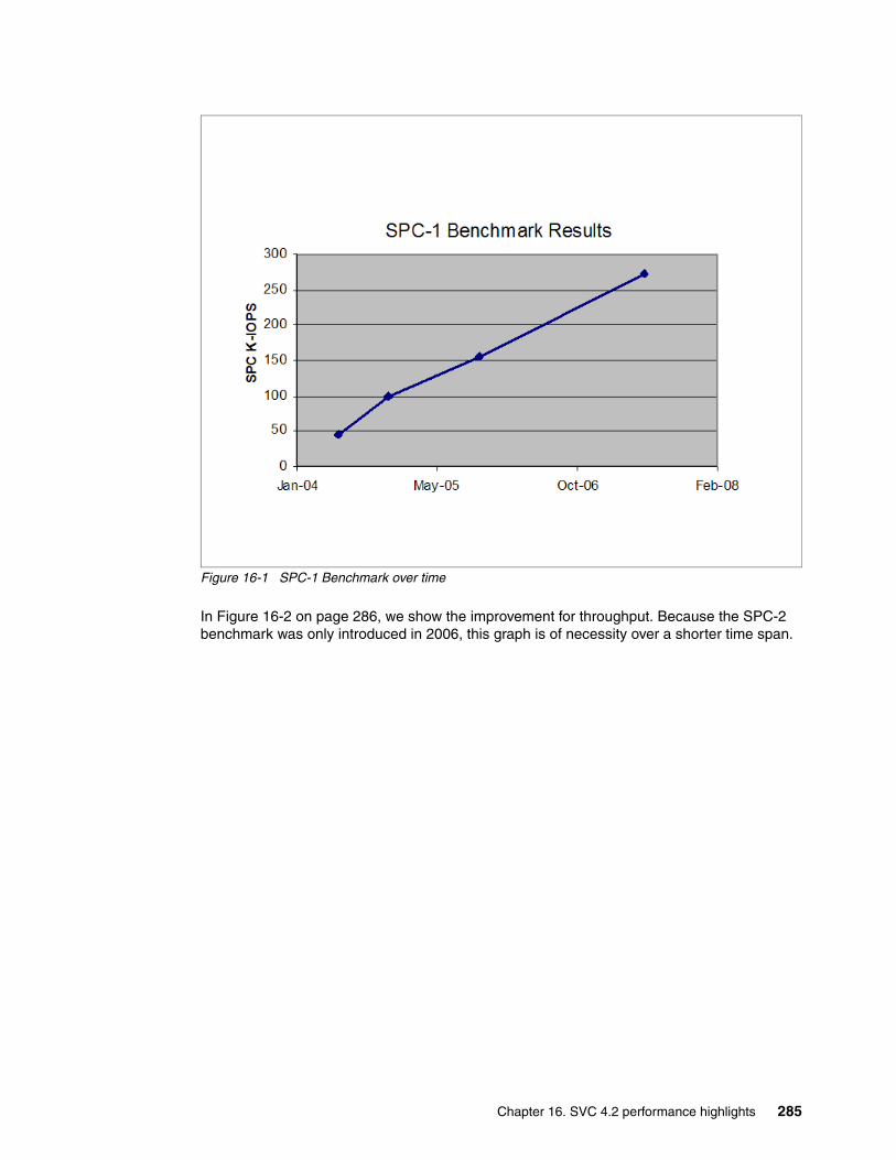
Figure 16-1 SPC-1 Benchmark over time
In Figure 16-2 on page 286, we show the improvement for throughput. Because the SPC-2 benchmark was only introduced in 2006, this graph is of necessity over a shorter time span.
Chapter 16. SVC 4.2 performance highlights 285
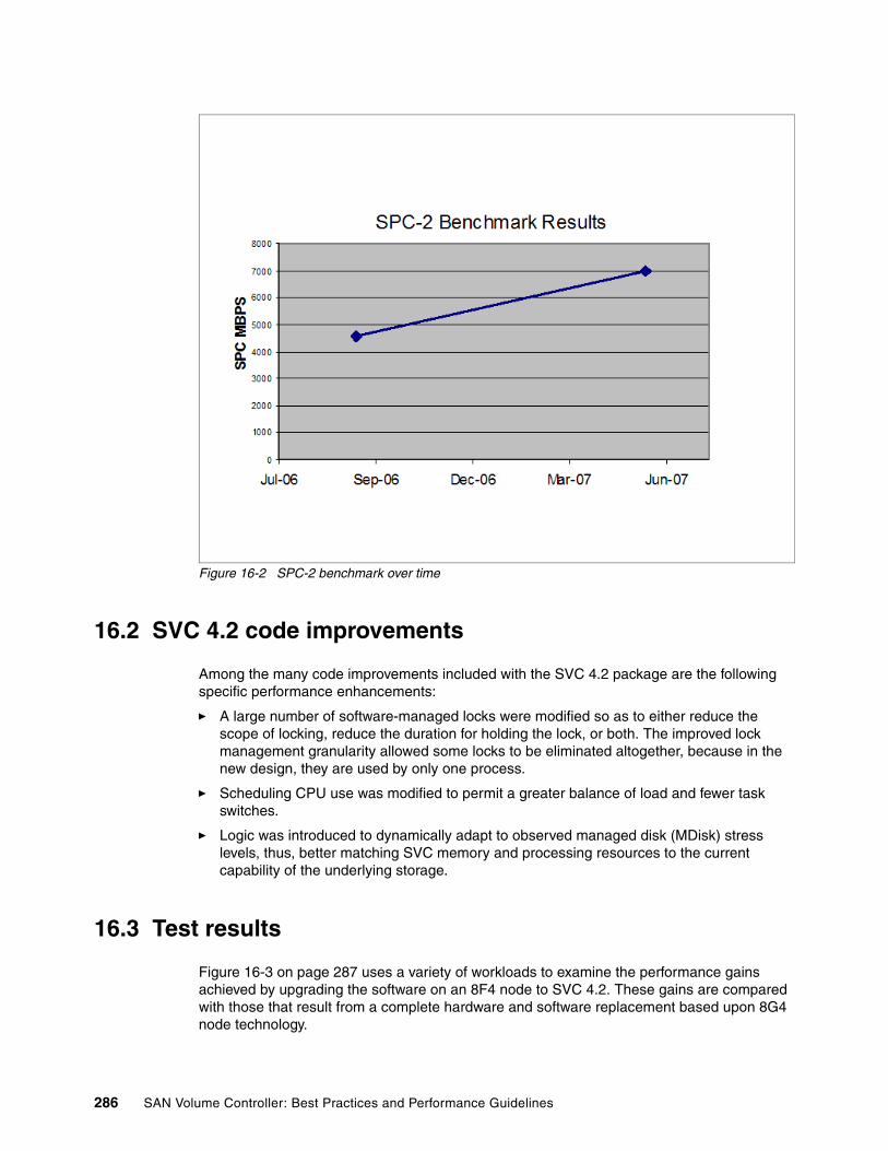
Figure 16-2 SPC-2 benchmark over time
16.2 SVC 4.2 code improvements
Among the many code improvements included with the SVC 4.2 package are the following specific performance enhancements:
� A large number of software-managed locks were modified so as to either reduce the scope of locking, reduce the duration for holding the lock, or both. The improved lock management granularity allowed some locks to be eliminated altogether, because in the new design, they are used by only one process.
� Scheduling CPU use was modified to permit a greater balance of load and fewer task switches.
� Logic was introduced to dynamically adapt to observed managed disk (MDisk) stress levels, thus, better matching SVC memory and processing resources to the current capability of the underlying storage.
16.3 Test results
Figure 16-3 on page 287 uses a variety of workloads to examine the performance gains achieved by upgrading the software on an 8F4 node to SVC 4.2. These gains are compared with those that result from a complete hardware and software replacement based upon 8G4 node technology.
286 SAN Volume Controller: Best Practices and Performance Guidelines
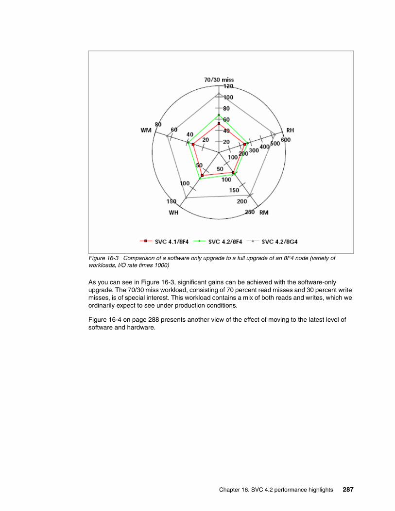
Figure 16-3 Comparison of a software only upgrade to a full upgrade of an 8F4 node (variety of workloads, I/O rate times 1000)
As you can see in Figure 16-3, significant gains can be achieved with the software-only upgrade. The 70/30 miss workload, consisting of 70 percent read misses and 30 percent write misses, is of special interest. This workload contains a mix of both reads and writes, which we ordinarily expect to see under production conditions.
Figure 16-4 on page 288 presents another view of the effect of moving to the latest level of software and hardware.
Chapter 16. SVC 4.2 performance highlights 287

Figure 16-4 Two node SVC cluster with random 4k throughput
Figure 16-5 presents a more detailed view of performance on this specific workload. Figure 16-5 shows that the SVC 4.2 software-only upgrade boosts the maximum throughput for the 70/30 workload by more than 30%. Thus, a significant portion of the overall throughput gain achieved with full hardware and software replacement comes from the software enhancements.
Figure 16-5 Comparison of a software only upgrade to a full upgrade of an 8F4 node 70/30 miss workload
2 Node - 70/30 4K Random Miss
0
5
10
15
20
25
30
0 20000 40000 60000 80000 100000 120000
Throughput (IO/s)
Res
pons
e Ti
me
(ms)
4.1.0 8F4 4.2.0 8F4 4.2.0 8G4
288 SAN Volume Controller: Best Practices and Performance Guidelines
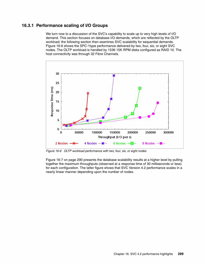
16.3.1 Performance scaling of I/O Groups
We turn now to a discussion of the SVC’s capability to scale up to very high levels of I/O demand. This section focuses on database I/O demands, which are reflected by the OLTP workload; the following section then examines SVC scalability for sequential demands. Figure 16-6 shows the SPC-1type performance delivered by two, four, six, or eight SVC nodes. The OLTP workload is handled by 1536 15K RPM disks configured as RAID 10. The host connectivity was through 32 Fibre Channels.
Figure 16-6 OLTP workload performance with two, four, six, or eight nodes
Figure 16-7 on page 290 presents the database scalability results at a higher level by pulling together the maximum throughputs (observed at a response time of 30 milliseconds or less) for each configuration. The latter figure shows that SVC Version 4.2 performance scales in a nearly linear manner depending upon the number of nodes.
Chapter 16. SVC 4.2 performance highlights 289
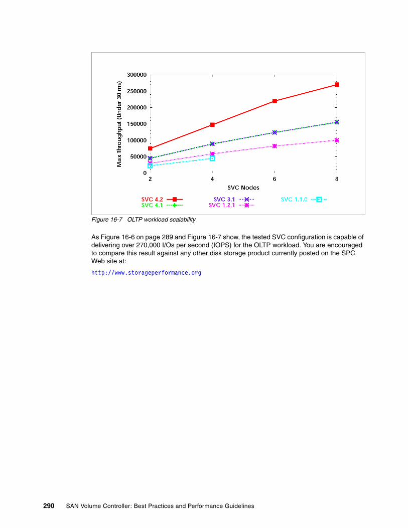
Figure 16-7 OLTP workload scalability
As Figure 16-6 on page 289 and Figure 16-7 show, the tested SVC configuration is capable of delivering over 270,000 I/Os per second (IOPS) for the OLTP workload. You are encouraged to compare this result against any other disk storage product currently posted on the SPC Web site at:
http://www.storageperformance.org
290 SAN Volume Controller: Best Practices and Performance Guidelines

Related publications
The publications listed in this section are considered particularly suitable for a more detailed discussion of the topics covered in this book.
IBM Redbooks publications
For information about ordering these publications, see “How to get IBM Redbooks publications” on page 292. Note that some of the documents referenced here might be available in softcopy only:
� IBM System Storage SAN Volume Controller, SG24-6423-05
� Get More Out of Your SAN with IBM Tivoli Storage Manager, SG24-6687
� IBM Tivoli Storage Area Network Manager: A Practical Introduction, SG24-6848
� IBM System Storage: Implementing an IBM SAN, SG24-6116
Other resources
These publications are also relevant as further information sources:
� IBM System Storage Open Software Family SAN Volume Controller: Planning Guide, GA22-1052
� IBM System Storage Master Console: Installation and User’s Guide, GC30-4090
� IBM System Storage Open Software Family SAN Volume Controller: Installation Guide, SC26-7541
� IBM System Storage Open Software Family SAN Volume Controller: Service Guide, SC26-7542
� IBM System Storage Open Software Family SAN Volume Controller: Configuration Guide, SC26-7543
� IBM System Storage Open Software Family SAN Volume Controller: Command-Line Interface User's Guide, SC26-7544
� IBM System Storage Open Software Family SAN Volume Controller: CIM Agent Developers Reference, SC26-7545
� IBM TotalStorage Multipath Subsystem Device Driver User’s Guide, SC30-4096
� IBM System Storage Open Software Family SAN Volume Controller: Host Attachment Guide, SC26-7563
© Copyright IBM Corp. 2008. All rights reserved. 291
Referenced Web sites
These Web sites are also relevant as further information sources:
� IBM TotalStorage home page:
http://www.storage.ibm.com
� SAN Volume Controller supported platform:
http://www-1.ibm.com/servers/storage/support/software/sanvc/index.html
� Download site for Windows SSH freeware:
http://www.chiark.greenend.org.uk/~sgtatham/putty
� IBM site to download SSH for AIX:
http://oss.software.ibm.com/developerworks/projects/openssh
� Open source site for SSH for Windows and Mac:
http://www.openssh.com/windows.html
� Cygwin Linux-like environment for Windows:
http://www.cygwin.com
� IBM Tivoli Storage Area Network Manager site:
http://www-306.ibm.com/software/sysmgmt/products/support/IBMTivoliStorageAreaNetworkManager.html
� Microsoft Knowledge Base Article 131658:
http://support.microsoft.com/support/kb/articles/Q131/6/58.asp
� Microsoft Knowledge Base Article 149927:
http://support.microsoft.com/support/kb/articles/Q149/9/27.asp
� Sysinternals home page:
http://www.sysinternals.com
� Subsystem Device Driver download site:
http://www-1.ibm.com/servers/storage/support/software/sdd/index.html
� IBM TotalStorage Virtualization home page:
http://www-1.ibm.com/servers/storage/software/virtualization/index.html
How to get IBM Redbooks publications
You can search for, view, or download IBM Redbooks publications, Redpapers, Technotes, draft publications and Additional materials, as well as order hardcopy IBM Redbooks publications, at this Web site:
ibm.com/redbooks
Help from IBM
IBM Support and downloads
ibm.com/support
292 SAN Volume Controller: Best Practices and Performance Guidelines

IBM Global Services
ibm.com/services
Related publications 293

294 SAN Volume Controller: Best Practices and Performance Guidelines

Index
Numerics500 86
Aacceptance xvaccess 2, 22, 34, 62, 88, 106, 117, 145, 171, 216, 250access pattern 122accident 146active 36, 62, 108, 144, 195, 220, 279active state 63adapters 69, 106, 171, 212, 224, 248adds 80, 204Admin 35, 205admin password 51administration 42, 90, 243administrator 22, 42, 78, 145, 204, 244, 260administrators 198, 204, 238, 284advanced copy 22, 146aggregate 62, 105AIX xiv, 66, 170, 201, 248, 264AIX host 179, 186, 266AIX LVM admin roles 205alert 10, 159, 216alerts 3, 235, 257Alias 17alias 16aliases 14, 241alignment 209allocation algorithm 115amount of I/O 26, 101, 122, 161analysis 78, 163, 225, 282application
availability 88, 99, 212performance 57, 88, 98, 119, 144, 202, 227
applications 12, 22, 35, 66, 99, 122, 144, 171, 201architecture 4, 62, 112, 184, 284architectures 106, 193area 183, 210, 262areas xiv, 33, 169, 203, 260array 2, 22, 61, 87, 98, 130, 156, 195, 204, 242, 254arrays 2, 22, 68, 88, 98, 119, 157, 205, 238, 260asymmetric 29asynchronous 82, 125, 144asynchronously 144attached 3, 26, 58, 62, 86, 114, 169, 203, 240, 260attention 4, 247attributes 85audit 33Audit log 48audit log 46authorization 40auto 116automatically discover 180Automation 53
© Copyright IBM Corp. 2008. All rights reserved.
automation 35, 125auxiliary 163availability 5, 69, 88, 98, 176, 214, 256, 259
Bbackend storage controller 140, 276back-end storage controllers 161background copy 159background copy rate 159backup 3, 52, 156, 192, 203, 256, 268balance 15, 63, 93, 98, 114, 160, 176, 205, 257, 286balanced 15, 63, 111, 136, 172, 209balancing 19, 93, 114, 172, 206band 99, 129Bandwidth 169bandwidth 2, 23, 71, 109, 122, 156, 172, 203, 244bandwidth requirements 10baseline 81, 132Basic 5, 34basic 2, 23, 35, 130, 170, 238, 258, 262best practices xiii, 1, 88, 99, 114, 158, 169between 3, 27, 59, 62, 88, 100, 114, 143, 171, 204, 216, 256, 263, 283BIOS 31, 193blade 14BladeCenter 10blades 14block 56, 69, 114, 147, 202, 229block size 69, 135, 204block-for-block translation 115blocking 2BM System Storage SAN Volume Controller Host Attach-ment User’s Guide Version 4.2.0 169, 193boot 172boot device 190bottlenecks 135, 202boundary crossing 208Brocade 4, 23, 269buffer 148, 230buffering 56buffers 116, 158, 170, 213bus 22, 182, 224, 284
Ccache 2, 22, 56, 61, 86, 102, 118, 144, 170, 202–204, 229, 247, 256, 281, 284cache disabled 30, 125, 150cache mode 127cache-enabled 158caching 22, 69, 87, 122, 146cap 101capacity 9, 22, 73, 87, 98, 114, 147, 207, 241, 280cards 4, 62, 193certified xiv, 11, 254
295
changes 3, 25, 43, 81, 87, 135, 146, 170, 212, 237, 257, 260channel 187chdev 187choice 26, 58, 69, 88, 122, 177CIMOM 35, 216Cisco 2, 23, 243, 254, 269classes xiv, 100, 257CLI 65, 89, 114, 148, 182, 227, 261
commands 44, 72, 89, 273client 191, 208cluster 2, 21, 34, 56, 62, 86, 98, 114, 144, 171, 216, 244, 260, 288
creation 51, 114IP address 39, 217
Cluster configuration 53cluster ID 47cluster partnership 52clustering 184clustering software 184clusters 11, 22, 35, 143, 184, 216, 238, 277code update 30combination 136, 145, 243command 30, 36, 63, 89, 114, 148, 173, 207, 216, 249, 257, 265command prompt 38commit 151compatibility 30, 35, 246complexity 7, 284conception 12concepts xiiiconcurrent 30, 35, 136, 182, 273configuration 1, 23, 34, 57, 61, 86, 98, 115, 144, 170, 202, 216, 237, 256, 260, 289configuration backup 52configuration changes 180configuration data 180, 270configuration file 52configuration node 39, 281configuration parameters 164, 182configure 10, 88, 188, 212, 216, 237congested links 2congestion 2, 232
control 3connected 2, 57, 62, 169, 217, 239, 256, 261connection 36, 77, 185, 216, 240, 271connections 9, 35, 62, 190, 240connectivity 189, 216, 245, 260, 289consistency 40, 143, 197consistency group 147consistency groups 40, 147consistent 29, 130, 162, 197, 234, 243consolidation 98, 284containers 208control 22, 73, 93, 125, 145, 171, 205, 238, 284controller port 86copy 22, 44, 56, 100, 116, 144, 197, 229, 238, 256, 267copy rate 150copy service 144copy services 22, 58, 116, 144
core 4, 254core fabric 11core switches 5correctly configured 163, 218corrupted 197corruption 20, 76cost 11, 88, 98, 146, 202, 246counters 198, 228create a FlashCopy 151critical xiv, 34, 69, 90, 202current 23, 35, 56, 68, 146, 182, 217, 240, 261, 286CWDM 11
Ddata 3, 22, 47, 63, 87, 100, 115, 144, 171, 202, 215, 237, 254, 259
consistency 151data formats 192data integrity 118, 148data layout 112, 116, 204Data layout strategies 213data migration 156, 192data path 80, 115data pattern 202data rate 101, 136, 167, 228data structures 209data traffic 10database 3, 81, 122, 152, 179, 203, 228, 241, 260, 289
log 204date 56, 217, 241, 266DB2 container 209DB2 I/O characteristics 209db2logs 209debug 77, 262dedicate bandwidth 12default 34, 62, 114, 160, 173, 217, 249default values 69defined 18, 140, 147, 204, 220, 249degraded 133, 144, 261delay 130, 151delete
a VDisk 117deleted 150demand 100, 289dependency 111, 154design 1, 22, 81, 99, 130, 178, 208, 255, 286destage 29, 56, 69, 87, 129device 2, 69, 106, 130, 146, 172, 206, 219, 237, 264device driver 146, 185diagnose 15, 163, 254diagnostic 186, 270different vendors 146director 5directors 4disabled 30, 57, 125, 144, 247disaster 25, 145, 197, 255discovery 63, 94, 179, 245disk 2, 22, 56, 67, 85, 98, 114, 147, 179, 202, 225, 238, 256, 269, 290
latency 29, 203
296 SAN Volume Controller: Best Practices and Performance Guidelines

disk access profile 122disk groups 25Disk Magic 136disruptive 3, 30, 114, 243distance 11, 158, 254
limitations 11distances 11DMP 177DNS 34documentation 1, 38, 238domain 4, 74, 98Domain ID 20, 250domain ID 20domains 98download 199, 274downtime 57, 115, 151driver 30, 62, 146, 185, 249, 260drops 105, 231DS4000 26, 62, 89, 102, 199, 203, 234, 270DS4000 Storage
Server 203DS4100 86DS4500 57, 218DS4800 17, 69, 86DS6000 xiv, 62, 89, 102, 188, 270DS8000 xiv, 17, 62, 86, 102, 188, 207, 270dual fabrics 14DWDM 11
Eedge xv, 2edge fabric 4edge switch 3edge switches 4efficiency 121element 23eliminates 78e-mail xvi, 12, 198, 244EMC 61EMC Symmetrix 63enable 7, 22, 51, 119, 151, 188, 203, 227, 249enforce 9Enterprise 62, 235, 269error 11, 36, 61, 90, 143, 170, 216, 238, 260Error Code 68error handling 68error log 67, 247, 264errors 11, 34, 66, 143, 170, 247, 260ESS xiv, 62, 89, 102, 207, 274ESS storage 63Ethernet 2, 39evenly balancing I/Os 212event 3, 29, 62, 98, 122, 145, 188, 235events 34, 146, 235, 272exchange 151execution throttle 194expand 26expansion 3, 211extenders 158extension 11
extent 25, 71, 85, 114, 204size 114, 208
extent migration 27extent size 114, 207extent sizes 114, 207extents 27, 61, 89, 114, 209
FFabric 20, 27, 224, 269fabric 1, 22, 135, 157, 170, 217, 246, 260
isolation 176login 178
fabric outage 3fabrics 6, 171, 217failed node 56failover 29, 62, 122, 170, 260failure boundaries 100, 206FAStT 14, 194
storage 14FAStT200 86fault tolerant 88FC xiv, 2, 69, 178fcs 19, 187, 248fcs device 187features 22, 146, 189, 237, 256, 260Fibre Channel 2, 56, 62, 158, 169, 248, 254, 260
ports 10, 62routers 158traffic 3
Fibre Channel (FC) 171Fibre Channel ports 62, 172, 250, 275file system 148, 194, 209file system level 197filesets 191firmware 163, 247, 262flag 118, 162flash 56, 147FlashCopy 23, 40, 56, 66, 87, 111, 116, 144, 229, 261
applications 68, 111bitmap 147mapping 30, 78, 147prepare 150rules 158source 23, 67, 116, 147Start 116target 126, 147, 229
FlashCopy mapping 148FlashCopy mappings 117, 147flexibility 23, 122, 146, 184, 238flow 3, 136flush the cache 182force flag 118format 47, 77, 192, 239, 258, 282frames 2free extents 121front panel 36full bandwidth 5function 30, 66, 89, 112, 145, 194, 214, 256, 268functions 22, 34, 66, 144, 189, 231, 262
Index 297

Ggateway 34gateway IP address 40GB 22, 57, 147, 242Gb 4, 69, 231General Public License (GNU) 199Global 23, 40, 56, 117, 144, 221, 277Global Mirror 23, 144, 222Global Mirror relationship 158gmlinktolerance 160GNU 199governing throttle 122grain 87granularity 114, 197, 286graph 81, 135, 230, 285graphs 27, 183group 9, 23, 56, 72, 98, 114, 143, 172, 204, 227, 241, 254, 269groups 10, 25, 40, 73, 85, 113, 147, 173, 206, 230, 274, 289growth 81, 211GUI 13, 30, 35, 63, 89, 114, 148, 177, 216, 257, 267
HHACMP 35, 189hardware xiii, 2, 23, 34, 58, 62, 89, 100, 163, 193, 242, 260, 284
selection 5HBA 10, 22, 176, 187, 194, 224, 244, 260HBAs 13, 133, 171–172, 194, 203, 224, 247health 190, 216, 271healthy 164, 219heartbeat 159help xv, 9, 36, 56, 66, 101, 113, 156, 186, 204, 229, 238, 257, 260heterogeneous 22, 262hops 3host 2, 22, 35, 56, 62, 86, 109, 114, 144, 169, 201, 215, 238, 260
configuration 15, 117, 158, 205, 261creating 17definitions 117, 180, 203HBAs 15information 31, 177, 225, 244, 264showing 27systems 26, 169, 203, 260zone 14, 114, 171, 262
host bus adapter 193host level 172host mapping 129, 172, 261host type 62, 244host zones 17, 241
II/O governing 122I/O governing rate 124I/O group 9, 23, 56, 114, 143, 177, 229, 244, 256I/O groups 16, 114, 167, 180, 234I/O performance 56, 187, 210
I/O response time 132IBM storage products xiiiIBM Subsystem Device Driver 62, 89, 118, 146, 189IBM TotalStorage Productivity Center 20, 159, 217, 258, 262ICAT 50identification 90, 173identify 36, 61, 89, 100, 148, 188, 229identity 47IEEE 192image 23, 57, 87, 115, 147, 172, 205, 241Image Mode 115, 145Image mode 27, 119, 145, 206image mode 26, 116, 149, 179, 206image mode VDisk 28, 116, 211Image Mode VDisks 146image mode virtual disk 125implement 3, 25, 59, 89, 193, 243, 258implementing xiii, 1, 101, 184, 257import 116improvements 23, 59, 111, 137, 190, 283Improves 22in-band 129information 1, 30, 33, 56, 63, 121, 148, 179, 201, 216, 238, 257, 260infrastructure 100, 125, 146, 218, 246initial configuration 176initiate 40initiating 78initiators 86, 185install 6, 38, 157, 193, 227, 246installation 1, 88, 216, 238, 254insufficient bandwidth 3integrity 118, 148Inter Switch Link 2interface 22, 50, 148, 169, 216, 250interoperability 10, 246interval 163, 228introduction 27, 79, 258, 284iogrp 118, 171IOPS 170, 202, 284IP 11, 33, 216IP address 34IP traffic 12ISL 2, 241ISL oversubscription 3ISLs 3, 239isolated 74, 176isolation 2, 63, 90, 101, 176, 261
Jjournal 194, 204
Kkernel 194key 38, 122, 179, 208, 242keys 38, 185
298 SAN Volume Controller: Best Practices and Performance Guidelines

Llast extent 114latency 29, 129, 151, 203LBA 67level 13, 23, 35, 62, 88, 131, 144, 172, 212, 233, 260, 287
storage 78, 197, 246, 261levels 4, 34, 68, 87, 102, 132, 184, 211, 244, 262, 286lg_term_dma 187library 195license 25, 269light 101, 202, 271limitation 36, 183, 228limitations 1, 25, 35, 145, 203, 270limiting factor 130limits 22, 35, 130, 144, 183, 212lines of business 206link 2, 25, 36, 144, 191, 257, 271
bandwidth 12, 159latency 158
links 2, 158, 217, 254, 270Linux xiii, 194, 264list 13, 22, 47, 66, 87, 115, 158, 195, 238, 260list dump 53livedump 281load balance 122, 177Load balancing 190load balancing 114, 193loading 71, 111, 143LOBs 206location 38, 77, 87, 133, 202, 238locking 184, 286log 46, 67, 146, 230, 247, 257, 264logged 36, 75Logical Block Address 67logical drive 62, 92, 187, 204, 208logical unit number 145logical units 25login 36, 122, 171logins 171logs 33, 152, 204, 247, 266long distance 158loops 70, 255LPAR 192, 213LU 172LUN 12, 26, 61, 85, 102, 125, 145, 170, 204, 222, 241, 262
access 146, 185LUN mapping 90, 172, 274LUN masking 20, 75, 262LUN Number 63, 90LUN per 102, 206LUNs 62, 86, 97, 146, 172, 205, 227, 242, 276LVM 117, 190, 205
MM12 4maintaining passwords 33maintenance 31, 36, 160, 178, 248, 260
maintenance procedures 36, 250, 278maintenance window 160manage 22, 33, 62, 113, 147, 170, 206, 216, 246, 258managed disk 115, 213, 275managed disk group 119, 213Managed Mode 70, 119management xiii, 7, 34, 56, 98, 144, 170, 205, 216, 254, 262, 286
capability 171, 213port 171, 235software 173
managing 22, 39, 58, 170, 208, 238, 258, 260map 65, 129, 157, 173map a VDisk 176mapping 30, 61, 90, 106, 117, 148, 170, 206, 261mappings 40, 117, 147, 185, 261maps 147, 212, 279mask 10, 34, 146, 171, 279masking 12, 26, 75, 157, 171, 262master 31, 34, 148master console 34, 149max_xfer_size 187–188maximum IOs 209MB 12, 57, 70, 114, 188, 207Mb 12, 25McDATA 10, 23, 269MDGs 85, 97, 114, 206, 273MDisk 27, 52, 61, 85, 100, 114, 146, 177, 204, 222, 241, 261, 286
adding 89, 132removing 186
MDisk group 116, 146, 204media 66, 164, 227, 275member xiii, 16members 14, 70, 260memory 22, 49, 147, 170, 204, 229, 245, 256, 281, 286message 20, 36, 163, 249messages 177, 250, 272metric 81, 130, 166, 230Metro 23, 40, 116, 144, 221, 277Metro Mirror 23, 144, 230Metro Mirror relationship 151microcode xiii, 68migrate 10, 59, 116, 156, 172migrate data 119, 191migrate VDisks 117migration 2, 26, 66, 119, 156, 179, 245, 258migration scenarios 9mirrored 22, 129, 159, 197mirroring 11, 117, 144, 190misalignment 208mkrcrelationship 162Mode 70, 96, 115, 145, 174, 245, 265mode 23, 50, 56, 87, 97, 115, 145, 171, 205, 254, 280
settings 158monitor 20, 43, 132, 159, 215, 246, 262monitored 81, 132, 164, 197, 260monitoring 56, 79, 159, 169, 215, 246, 275monitors 136, 228mount 118, 151, 256
Index 299

MPIO 189, 249multipath drivers 89, 247multipath software 184multipathing xiii, 30, 62, 170, 248, 259Multipathing software 178multipathing software xiv, 176, 251multiple paths 122, 176, 261multiple vendors 10multiplexing 11
NName Server 34name server 178, 250, 271names 16, 47, 114, 192, 251nameserver 178naming 14, 47, 64, 88, 114, 244naming conventions 52new disks 179new MDisk 92no virtualization 115NOCOPY 150node 2, 24, 39, 56, 75, 86, 101, 114, 143, 170, 217, 247, 256, 260, 284
adding 25failure 29, 56, 122, 178port 14, 122, 164, 171, 217, 261
nodes 3, 22, 39, 56, 74, 86, 114, 154, 171, 217, 247, 256, 261, 283noise 130non 7, 22, 76, 116, 155, 177, 206, 231, 243, 258, 264non-disruptive 119non-preferred path 121num_cmd_elem 187–188
Ooffline 30, 39, 57, 68, 89, 118, 146, 177, 224, 248, 261online xv, 89, 112, 117, 148, 219, 248, 261OnLine Transaction Processing (OLTP) 203online transaction processing (OLTP) 203–204open systems xivoperating system (OS) 202operating systems 176, 208, 249, 264Operator 40optimize 112, 283Oracle 190, 206ordered list 115organizations 12OS 51, 170, 213, 247, 277overlap 14overloading 140, 167, 236oversubscription 3overview 27, 35, 85, 204, 259
Pparameters 29, 47, 61, 86, 122, 164, 172, 203, 245partition 191partitions 69, 136, 191, 208partnership 52, 159
password 50passwords 33path 3, 29, 35, 57, 62, 101, 115, 170, 213, 222, 248, 260
selection 189paths 8, 30, 62, 121, 170, 222, 245, 261peak 3, 159per cluster 24, 114, 147, 230performance xiii, 3, 22, 56, 61, 87, 98, 113, 144, 169, 201, 217, 237, 260, 283
degradation 63, 102, 144performance advantage 88, 105performance characteristics 100, 116, 199, 213performance improvement 26, 119, 231, 284performance monitoring 166, 172performance requirements 59permanent 163permit 3, 286persistent 89, 184PFE xivphysical 11, 22, 61, 87, 139, 148, 169, 202, 229, 241, 255physical volume 191, 212ping 39PiT 126planning 15, 87, 97, 130, 165, 203plink 38plink.exe 38PLOGI 178point-in-time 145point-in-time copy 146policies 189policy 30, 51, 101, 115, 185, 246pool 22, 71, 100, 160port 2, 22, 61, 86, 133, 164, 170, 217, 238, 254, 261
types 63port layout 4port zoning 12ports 2, 23, 57, 62, 86, 133, 170, 217, 241, 254, 261power 29, 182, 250, 256, 275PPRC 56preferred 11, 26, 34, 56, 62, 114, 160, 171, 207, 261preferred node 56, 114, 160, 177preferred path 57, 62, 121, 177preferred paths 122, 177, 264prepare a FlashCopy 165prepared state 164primary 25, 39, 87, 98, 125, 144, 206priority 36private 38private key 38problems 2, 31, 35, 63, 89, 129, 157, 186, 202, 242, 254, 259productivity xvprofile xiv, 69, 93, 122, 274progress 30, 50, 56properties 130, 195protect 159protecting 70provisioning 88, 102pSeries 19, 76, 199public key 38
300 SAN Volume Controller: Best Practices and Performance Guidelines

PuTTY 34, 268PuTTY session 45PVID 192PVIDs 192
Qquad 4queue depth 85, 182, 188, 193–194, 212quickly 2, 40, 78, 129, 150, 176, 224, 243, 254quiesce 117, 151, 181
RRAID 70, 88, 119, 162, 204, 241, 289RAID array 130, 164, 205RAID arrays 130, 205RAID types 205ranges 130RDAC 62, 89Read cache 202reboot 117, 182rebooted 191receive 95, 231, 249recovery 25, 51, 66, 92, 119, 152, 170, 275recovery point 159Redbooks Web site 292
Contact us xvredundancy 2, 39, 62, 112, 159, 171, 218, 262redundant 22, 39, 74, 159, 171, 212, 224, 260redundant paths 171redundant SAN 74registry 179, 266relationship 20, 62, 116, 144, 191, 221, 277reliability 15, 89, 237, 284remote cluster 31, 158, 221remote copy 125, 147remote mirroring 11remotely 34remount 129removed 20, 59, 117, 179rename 38, 157, 267replicate 145replication 144, 246, 258reporting 80, 131, 235, 263reports 133, 179, 215reset 36, 178, 247, 260resources 22, 78, 93, 98, 125, 160, 170, 209, 229, 281, 286restart 35, 157, 256restarting 159restarts 178restore 53, 166, 192restricting access 184rights 40risk 78, 89, 98, 146, 257role 40, 203roles 40, 205root 133, 185, 235, 248, 274round 93, 158, 209round-robin 94
route 160router 158routers 158routes 7routing xiv, 4, 62, 255RPQ 3, 194, 246RSCN 178rules 38, 80, 141, 158, 170, 262
SSAN xiii, 1, 21, 33, 62, 114, 157, 169, 212, 215, 237, 254, 259, 284
availability 176fabric 1, 157, 176, 218
SAN configuration 1SAN fabric 1, 157, 171, 217, 262SAN Volume Controller xiii, 1, 15, 22, 33, 119, 169, 257, 262
multipathing 194SAN zoning 122, 220, 243, 260scalability 2, 21, 289scalable 1, 22scale 23, 112, 289scaling 58, 112, 283scan 179scripts 125, 182SCSI 67, 121, 178, 274
commands 184, 274SCSI disk 192SCSI-3 184SDD xiii, 15, 62, 89, 118, 146, 170, 189, 211, 247, 264SDD for Linux 194SDDDSM 173, 264secondary 25, 39, 125, 145, 203secondary site 25, 145secure 50Secure Shell 46Security 40security 12, 40, 190, 247segment 69separate zone 18sequence 27, 42sequential 29, 87, 97, 115, 145, 170, 203, 241, 289sequential policy 115serial number 64, 172, 242, 274serial numbers 173Server 34, 62, 191, 212, 216, 243, 265server 3, 22, 69, 133, 151, 178, 202, 227, 240, 255, 271Servers 192, 203servers 3, 23, 34, 190, 201, 244, 256service 31, 34, 56, 80, 88, 144, 212, 230, 257, 260settings 39, 164, 186, 202, 262setup 34, 186, 207, 215, 254, 262share 20, 74, 88, 101, 139, 171, 209shared 12, 162, 185, 210, 218sharing 7, 138, 184, 203shutdown 56, 117, 157, 179, 256single storage device 177site 25, 58, 67, 125, 145, 196, 228, 244, 290slice 209
Index 301

slot number 19, 248slots 70snapshot 156, 241SNIA xiiiSNMP 34, 235Software xiii, 1, 15, 180, 246, 257, 260software xiii, 2, 34, 56, 146, 170, 212, 237, 257, 260, 286Solaris 194, 265solution 1, 34, 88, 130, 166, 202, 238, 256solutions xiii, 113, 238source 12, 23, 56, 67, 117, 144, 194, 227, 254sources 147, 256space 82, 87, 114, 147, 204, 245, 255spare 3, 26, 70, 87, 255speed 5, 22, 130, 162, 241, 271speeds 11, 83, 130, 254, 284split 6, 21, 73, 137, 147SSH 35, 217SSH keys 38standards 10, 216, 254start 11, 23, 35, 81, 140, 144, 172, 209, 216, 260state 36, 63, 119, 144, 170, 247, 282
synchronized 162statistics 87, 163, 198, 228statistics collection 163status 38, 66, 117, 148, 186, 216, 240, 261storage xiii, 1, 22, 34, 61, 85, 97, 114, 145, 169, 201, 215, 237, 254, 260, 284storage controller 14, 22, 61, 86, 99, 125, 145, 218, 276storage controllers 14, 22, 63, 88, 102, 139, 145, 216, 280Storage Manager 70, 166, 270Storage Networking Industry Association xiiistorage performance 81, 129, 233storage traffic 2streaming 111, 122, 203strip 208Strip Size Considerations 208strip sizes 208stripe 73, 98, 206striped 28, 93, 115, 145, 179, 204striped mode 150, 205striped mode VDisks 207striped VDisk 148stripes 208Striping 97striping 22, 68, 89, 105, 115, 205, 209, 283subnet 34subnet mask 40Subsystem Device Driver 62, 89, 118, 146, 174, 189, 249, 265superuser 50support xiii, 23, 34, 62, 89, 204, 238, 255, 284surviving node 29, 56SVC xiii, 1, 21, 33, 56, 62, 86, 98, 114, 144, 169, 204, 215, 237, 254, 259, 283SVC cluster 3, 21, 35, 64, 86, 99, 144, 176, 216, 268SVC configuration 52, 171, 242, 258, 279, 290SVC installations 5, 101, 254SVC master console 50, 152
SVC node 14, 25, 56, 146, 171, 217, 260SVC nodes 8, 22, 58, 75, 129, 154, 171, 221, 275, 284SVC software 172, 260svcinfo 40, 66, 89, 117, 148, 172, 261svcinfo lsmigrate 89svctask 40, 63, 89, 114, 157, 195, 268svctask dumpinternallog 47svctask finderr 47switch 2, 52, 57, 133, 163, 169, 217, 239, 254, 263
fabric 3, 247failure 3, 198interoperability 10
switch fabric 2, 171, 222switch ports 9, 219switches 2, 46, 57, 159, 215, 239, 254, 260, 286Symmetrix 61synchronization 159, 277Synchronized 162synchronized 144system 26, 35, 81, 112, 114, 147, 169, 203, 225, 248, 264, 283system performance 116, 194, 281
TT0 155tablespace 204, 209tape 3, 165, 171target 23, 56, 63, 86, 116, 144, 171, 227, 275target ports 75, 171targets 23, 147, 181tasks 41, 235, 246test 2, 27, 38, 57, 89, 105, 117, 158, 169, 211, 230tested 23, 89, 158, 170, 212, 246, 257, 262, 290This xiii, 1, 21, 35, 56, 62, 85, 97, 114, 146, 169, 201, 215, 238, 253, 260, 287thread 182, 208threshold 3, 144, 235thresholds 129throttle 122, 194throttles 122throughput 24, 57, 69, 88, 101, 130, 151, 177, 188, 202–204, 231, 284throughput based 202–203tier 88, 101time 2, 23, 39, 57, 62, 92, 99, 114, 144, 170, 202, 217, 241, 255, 259, 284Tivoli xiii, 166, 235Tivoli Storage Manager (TSM) 203tools 34, 169, 238, 262Topology 133, 217, 263topology 2, 217, 263traditional 12traffic 2, 57, 158, 177, 229
congestion 3Fibre Channel 10
transaction 68, 152, 187, 202transaction based 202–203Transaction log 204transceivers 11, 254transfer 62, 85, 122, 170, 202
302 SAN Volume Controller: Best Practices and Performance Guidelines
transit 2traps 34trends 81trigger 15, 242troubleshooting 13, 169, 245TSM xiii, 208tuning 136, 169, 213
UUID 90, 121, 280unique identifier 77, 172UNIX 152, 198Unmanaged MDisk 146unmanaged MDisk 119unmap 116unused space 114upgrade 30, 56, 163, 178, 236, 246, 273, 287upgrades 56, 178, 246, 274upgrading 31, 35, 58, 184, 231, 248, 277, 286upstream 2, 235URL 34users 4, 22, 40, 131, 179, 218, 257using SDD 146, 189, 250utility 89, 199
VVDisk 15, 23, 52, 56, 61, 85, 100, 113, 144, 172, 204, 225, 241, 261
creating 89migrating 119modifying 137showing 133
VDisk extents 66VDisk migration 67VIO clients 212VIO server 191, 212VIOC 191, 212VIOS 191, 212virtual disk 29, 95, 121, 192Virtualization xiiivirtualization 21, 78, 115, 204, 259virtualized storage 27virtualizing 7, 179volume abstraction 205volume group 75, 189VSAN 7VSANs 2VSCSI 191, 212
WWindows 2003 27, 34, 193workload 25, 41, 56, 62, 93, 99, 114, 158, 186, 202–203, 229, 287
throughput based 202transaction based 202
workload type 203workloads 3, 69, 88, 100, 125, 158, 170, 202, 286writes 29, 56, 69, 87, 102, 129, 144, 170, 204, 229, 287
WWNN 12, 63, 180, 250, 267WWNs 13WWPN 12, 26, 61, 86, 217, 241, 261WWPNs 13, 76, 171, 251, 261
Zzone 8, 157, 171, 220, 262zone name 19zoned 2, 171, 221, 241, 275zones 12, 157, 220, 241, 262zoneset 18, 221, 279Zoning 12, 241zoning 7, 25, 76, 122, 171, 220, 241, 260zoning configuration 12, 225, 241zSeries 112
Index 303

304 SAN Volume Controller: Best Practices and Performance Guidelines

(0.5” spine)0.475”<
->0.873”
250 <->
459 pages
SAN Volume Controller: Best Practices and Perform
ance Guidelines
SAN Volume Controller: Best Practices
and Performance Guidelines
SAN Volume Controller: Best
Practices and Performance
Guidelines
SAN Volume Controller: Best Practices and Perform
ance Guidelines

SAN Volume Controller: Best
Practices and Performance
Guidelines
SAN Volume Controller: Best
Practices and Performance
Guidelines

®
SG24-7521-00 ISBN 0738485780
INTERNATIONAL TECHNICALSUPPORTORGANIZATION
BUILDING TECHNICAL INFORMATION BASED ON PRACTICAL EXPERIENCE
IBM Redbooks are developed by the IBM International Technical Support Organization. Experts from IBM, Customers and Partners from around the world create timely technical information based on realistic scenarios. Specific recommendations are provided to help you implement IT solutions more effectively in your environment.
For more information:ibm.com/redbooks
®
SAN Volume Controller: Best Practices and Performance Guidelines
Read about best practices learned from the field
Learn about SVC performance advantages
Fine-tune your SVC
This IBM® Redbook captures some of the best practices based on field experience and details the performance gains that can be achieved by implementing the IBM System Storage™ SAN Volume Controller.
This book is intended for very experienced storage, SAN, and SVC administrators and technicians.
Readers are expected to have an advanced knowledge of the SVC and SAN environment, and we recommend these books as background reading:
� IBM System Storage SAN Volume Controller, SG24-6423
� Introduction to Storage Area Networks, SG24-5470� Using the SVC for Business Continuity, SG24-7371
Back cover