redacted public version of honeywell works safety basis ...designs for all but the piping support...
TRANSCRIPT

Honeywell
Performance Materials and TechnologiesHoneywellP.O. Box 4302768 North US 45 RoadMetropolis, IL 62960
January 14, 2013
U.S. Nuclear Regulatory CommissionATTN: Document Control Desk11555 Rockville PikeRockville, MD 20852
Docket No.: 40-3392License No.: SUB-526
SUBJECT: REDACTED PUBLIC VERSION OF HONEYWELL METROPOLIS WORKSSAFETY BASIS AND CORRECTIVE ACTION PLAN
Honeywell International, Inc. is providing the attached redacted public version ofHoneywell Metropolis Works Safety Basis and Corrective Action Plan, Response to NRCConfirmatory Order EA-12-157. This document's public and non-public versions had beenoriginally submitted on November 30, 2012, and an acknowledgment of receipt had beenissued by the NRC on December 20, 2012 (TAC L32788).
Honeywell Metropolis Works Safety Basis and Corrective Action Plan contains security-related sensitive information, and certain parts of this document shall be withheld frompublic disclosure under 10 CFR 2.390. These parts as well as Appendices A and B are"marked out" in the public version. The enclosed herewith is the redacted public version ofthe document where the marking "Security-Related Information Withhold Under 10 CFR2.390' included in the original submittal has been removed as requested by the NRC.
If you have any questions, or require additional information please contact Bob Stokes,Regulatory Affairs and Radiation Protection Manager, at (618) 524-6341.
rry ycou
lant Manager
Enclosure

PUBLIC VERSION
Honeywell International, Inc.Metropolis WorksDocket No. 40-3392License No. SUB-526
Safety Basis andCorrective Action Plan
Response to NRC Confirmatory Order EA-12-157
Revision 0Submittal Date: 2-&Neyefý6r--2•-•12
11 January 2013
PUBLIC VERSION
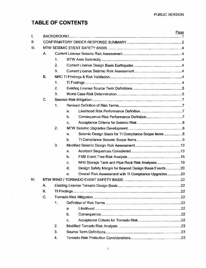
TABLE OF CONTENTS
1. BACKGROUND ........................................................................................................ 1II. CONFIRMATORY ORDER RESPONSE SUMMARY .................................................. 2
III. MTW SEISMIC EVENT SAFETY BASIS ................................................................... 4
A. Current License Seismic Risk Assessment .................................................... 4
1. MTW Area Seismicity ........................................................................... 42. Current License Design Basis Earthquake .......................................... 4
3. Current License Seismic Risk Assessment ......................................... 4B. NRC TI Findings & Risk Validation .................................................................. 4
1. TI Findings .......................................................................................... 4
2. Existing License Source Term Definitions ........................................... 53. Worst Case Risk Determination ........................................................... 5
C. Seismic Risk Mitigation ................................................................................... 71. Revised Definition of Risk Terms ........................................................ 7
a. Likelihood Risk Performance Definition .................................... 7
b. Consequence Risk Performance Definition .............................. 7c. Acceptance Criteria for Seismic Risk ....................................... 8
2. MTW Seismic Upgrades Development ............................................... 8
a. Seismic Design Basis for TI Compliance Scope Items ............. 8b. TI Compliance Seismic Scope Items ........................................ 9
3. Modified Seismic Design Risk Assessment ........................................ 13
a. Accident Sequences Considered .......................................... 13
b. FMB Event Tree Risk Analysis ............................................... 15
c. NH3 Storage Tank and Pipe Rack Risk Analyses .................. 19
d. Design Safety Margin for Beyond Design Basis Events ...... 20
e. Overall Risk Assessment with TI Compliance Upgrades ...... 20
IV. MTW W IND / TORNADO EVENT SAFETY BASIS ................................................... 22
A. Existing License Tornado Design Basis ........................................................ 22
B. TI Findings ................................................................................................... 22
C. Tornado Risk Mitigation ................................................................................ 22
1. Definition of Risk Terms ..................................................................... 22
a. Likelihood .............................................................................. 22
b. Consequence ........................................................................ 22
c. Acceptance Criteria for Tornado Risk ..................................... 22
2. Modified Tornado Risk Analysis ....................................................... 23
3. Source Term Definitions ................................................................... 23
4. Tornado Risk Protection Considerations ............................................. 23

PUBLIC VERSION
a. Vessels & Equipment ............................................................. 23
b. Tornado Vulnerabilities .......................................................... 24
5. TI Compliance Tornado Scope Items ............................................... 24
a. FMB Structure Tornado Protection ......................................... 24
b. Tank Farm NH3 Storage Tank Tornado Protection ................ 25
6. Modified Tornado Design Risk Assessment ...................................... 25
7. Overall Risk Assessment with TI Compliance Upgrades .................... 26
V. EMERGENCY RESPONSE PLAN .......................................................................... 27
R E F E R E N C E S ......................................................................................................................... 27
A P P E N D IC E S ........................................................................................................................... 2 8
ii

PUBLIC VERSION
BACKGROUND
In May 2012, NRC Staff inspectors performed a Temporary Instruction inspection (TI2600/015) at Metropolis Works (MTW) related to NRC's "Post Fukushima" nuclear facilitiesassessment effort. This TI evaluated external events considered in the facility's UF6 processequipment design and licensing bases. Key findings were reported in NRC TemporaryInstruction 2600-015 Inspection Report No. 40-3392/2012-006 [Ref 11:
" Inspectors noted some discrepancies between the current as-is condition of the FeedsMaterial Building (FMB) structure, equipment and piping versus the Integrated SafetyAnalysis (ISA). The various discrepancies identified were assessed significant enoughto have degraded the FMB's seismic capability below that represented in MTW'slicensing documents.
" It was assessed that certain tornado related accident sequences which could result inlarge UF6 releases were not adequately analyzed and mitigated via protective actions.
" The facility's Emergency Response Plan was assessed to be inadequate based on anapparent inability to effectively manage a larger-than-design UF6 release during certainseismic and tornado events.
During the time of the investigation, the MTW facility was shut down for annual maintenance.Following discussion with Region 2 leadership and in agreement with NRC ConfirmatoryOrder EA-12-157 [Ref 2], it was agreed the plant would not restart until plant leadership candemonstrate that the seismic and tornado design basis events result in no adverse impact toeither the public or on-site worker and that the Emergency Response Plan remains adequate.
This document provides the Safety and Design Basis information for facility retrofitsnecessary to comply with the requirements described in Section IV of the Confirmatory Order(CO) dated October 15, 2012.
Page 1 of 29

PUBLIC VERSION
I1. CONFIRMATORY ORDER RESPONSE SUMMARY
Honeywell MTW has reviewed the NRC TI inspection findings and will implement specificactions summarized below which have been determined to fully address all findingspresented in NRC's TI Inspection Report No. 40-3392/2012-006 [Ref 1]. Implementation ofthese action items is scheduled to be completed by 30 April 2013 at which time, pending finalNRC approval, the facility will be returned to operating status.
A brief summary of the major improvement projects and new Plant Features and Procedures(PFAPs) protecting against design basis seismic and tornado external event risks aresummarized below. Further details describing both the safety and design bases for theserisk mitigation actions can be found in Section III - MTW SEISMIC EVENT SAFETY BASIS ofthis document.
Summary of Major Improvement Projects
1. FM B StructUre IRetrofits,. ' Retr6fitstructural 'lumn' b"rae'andkcordriectibn •dditi6ns in FMB
1 FMB.Strs strUciure to me 475-yr deigh•basis EQ...Install restraintsisupports for Primary Cold Traps, Distillation Vessels2._______EquipmentRestraints and GF2 Plant HF Vaporizers to meet 475-yr design basis EQ.
3. FMBPii". "Repair/replace/upgrade liquid UF6 Piping supportsto meet 475-yr. .n. . design basis.EQ.
HF Storage Tanks to be decommissioned; a new Rail Car, Direct-to-
4. HF Storage Tanks Process unloading station to be installed to meet 475-yr design basisEQ requirements.
5. NH-13 Storage Tanks Upgrade NH3 Storage Tank supports and restraints to meet 475-yrdesign basis EQ.
6. Main Pipe Rack Retrofit Main Pipe Rack structure to meet 475-yrdesign basis EQ.In.tllseismicaly actuated slhut-off valves at Prirmary Cold 'Traps,Distillation vessels, HF Rail Car Unloading, NH3 Storage Tanks, HFVaporzers and GF2 Rectifiers (switches) to minimize hazardousmaterial release quantities during•, a seismic or tornado event.Partition off the Distillation process area in FMB to prevent hazardous
8. FMB Confinement material releases to environment below the 41 floor elevation tomitigate consequences to workers and public during a seismic event.Install tornado missile amor/netting protection at NH3 Storage Tanks
9. Wind/Tornado Protection and in vulnerable locations on FMB exterior to meet license basis for_ tornado risk.
Based on detailed engineering analyses and/or expert walk-down reviews conducted at theMTW facility, the following list of PFAPs must operate in the event of an earthquake or tomadoto ensure required risk performance requirements are satisfied:
I =---M
Page 2 of 29

PUBLIC VERSION
Page 3 of 29

PUBLIC VERSION
III. MTW SEISMIC EVENT SAFETY BASIS
A. Current License Seismic Risk Assessment
1. MTW Area Seismicity
The Metropolis Works facility is located in Metropolis, Illinois, just north of the Illinois-Kentucky border. This area is directly within the area of significant influence of theNew Madrid Seismic Zone (NMSZ), an area considered to feature the highestseismicity in the United States east of the Rocky Mountains. Although many smallerfaults exist in Illinois, Eastern Tennessee and Southern Indiana, the NMSZ representsthe controlling mechanism for maximum ground shaking intensities. The greatestearthquake hazards affecting the site are those associated with the New MadridSeismic Zone. The NMSZ is the site of the largest historical earthquakes in theconterminous United States, the 1811-1812 series (estimated -8 magnitude event).
2. Current License Design Basis Earthquake
Recognizing the magnitude and frequency of seismic activity in the MTW regionwithin the past 200 years, Honeywell retained Leighton & Associates [Ref 3] in 1991to analyze seismic risks and to develop conceptual seismic improvements. A 475-year return period earthquake (2x10⁻³ per year frequency of occurrence) was definedas the design basis earthquake for this analysis. The mean Peak GroundAcceleration (PGA) was calculated as 0.26g. Using both the 1990 BOCA NationalBuilding Code and 1991 Uniform Building Code as guidance documents, numerousstructural deficiencies were identified in the Feed Material Building (FMB) and tankfarm area in addition to inadequate equipment restraints and FMB piping supportsystems. In 1993 EQE Engineering & Design [Ref 4] developed conceptual retrofitdesigns for all but the piping support deficiencies. Honeywell subsequently installedthe EQE recommended retrofits in 1997. No documentation exists suggesting FMBpiping deficiencies were addressed at that time.
3. Current License Seismic Risk Assessment
In 2005, a seismic hazards assessment was conducted as part of an overall MTWIntegrated Safety Analysis (ISA) effort requested by NRC. Based on the 475-yeardesign basis earthquake analysis by Leighton & Associates and retrofits installed in1997, the MTW facility was determined to present no seismic risk to the public oremployees. Section 11.1 - Seismic of the MTW ISA Report [Ref 5] report states thatthe "plant is designed to withstand the 475-year earthquake with no safetyimplications" and thus "there are no design basis accidents associated with seismicevents".
B. NRC TI Findings & Risk Validation
1. TI Findings
As detailed in the NRC TI inspection report dated 9 August 2012, some seismicretrofits recommended by Leighton & Associates [REF 3] were not implemented. Asa result, further evaluation was required to determine whether a credible seismicevent could threaten the integrity of UF6 containment through piping/vessel rupture.The inspectors were unable to validate that Honeywell evaluated the consequencesof credible seismic events and subsequently designated plant features andprocedures and management measures to minimize the risk of unacceptable
Page 4 of 29

PUBLIC VERSION
consequences. In addition, the inspectors could not verify that the licenseeconsidered all potential accident sequences as a result of credible natural phenomenaevents during the development of the ISA.The TI inspection also identified concerns related to the UF6 and HF source terms
used as a basis for the MTW Emergency Response Plan (ERP).
2. Existing License Source Term Definitions
For purposes of defining the UF6 source term within the FMB during a seismic event,only "liquid" UF6 inventories are significant. Solid UF6 remains in a solid state uponrelease and does not appreciably contribute to hazardous material plumes. Vapordensities effectively minimize the mass of UF6 contained in vessels and pipingthereby contributing minimally to the source term. Table 1 summarizes liquid UF6mass in piping and vessels by FMB floor level.
Upon contact with moisture in air, UF6 hydrolyzes to form HF and U02F2. PerNureg/CR- 6410, B.3.5.2 [Ref 6] only a fraction of a UF6 release proceeds tostoichiometric hydrolysis due to UF6 liquid pool surface "freeze-over" and depositionof solid U02F2 precipitate on the pool surface which further limits air moisture contactwith the liquid UF6 pool surface. The worst case HF release in the FMB due to lossof containment of all liquid UF6 inventory from a design earthquake is determined tobe 28,400 lbs HF [Ref 7].
I
Page 5 of 29

PUBLIC VERSION
Page 6 of 29

PUBLIC VERSION
C. Seismic Risk Mitigation
1. Revised Definition of Risk Terms
a. Likelihood Risk Performance Definition
Per guidance in Nureg 1520, Appendix D, Natural Phenomena Hazards, and asdirected by Confirmatory Order EA-1 2-157 [Ref 2], the Likelihood Risk Terms forrare seismic external event risk analysis at MTW are defined as shown in Table2. These definitions apply only to seismic events and are not applicable to theTornado risk analysis discussed in Section IV - MTW Wind/Tornado EventSafety Basis. Note that these parameters differ from Nureg 1520 Appendix A,Table A-6 guidance but are consistent with Likelihood definitions utilized byexisting nuclear fuel cycle facilities for seismic risk analyses.
Table 2 - Seismic Total Risk Likelihood Categories
I
L Unlikely 1 2 Between 103 and 104 per event, per yearHighly Unlikely 1 Less than 104 per event, per year
b. Consequence Risk Performance Definition
Consequence Severity categories are defined based on MTW ISA Report,Section 4.3.1-Defining Consequence Severity Categories and Section 4.3.2-Worker Exposure Assumptions [Ref 5]. Table 3 provides enhanced values fornormalizing chemical exposure to values appropriate for the time intervals underconsideration. The rationale associated with exposure times are defined inMTW ISA Report, Section 4.3.2 [Ref 5].
Table 3 - Enhanced Definition of Consequence Severity Categories
I>100remTEDE I>25remTEDEI
Outside Controlled Area >25 rem TEDE >5 rem TEDE
Worker (elsewhere in room)(2.5-min exposure)
Worker (elsewhere in room)(5-min exposure)
Outside Controlled Area(30-min exposure)
Notes: 1. Use the conservative 5-minute exposure value for uranium.2. Use the conservative 5-minute exposure value for hydrogen fluoride.
Page 7 of 29
PUBLIC VERSION
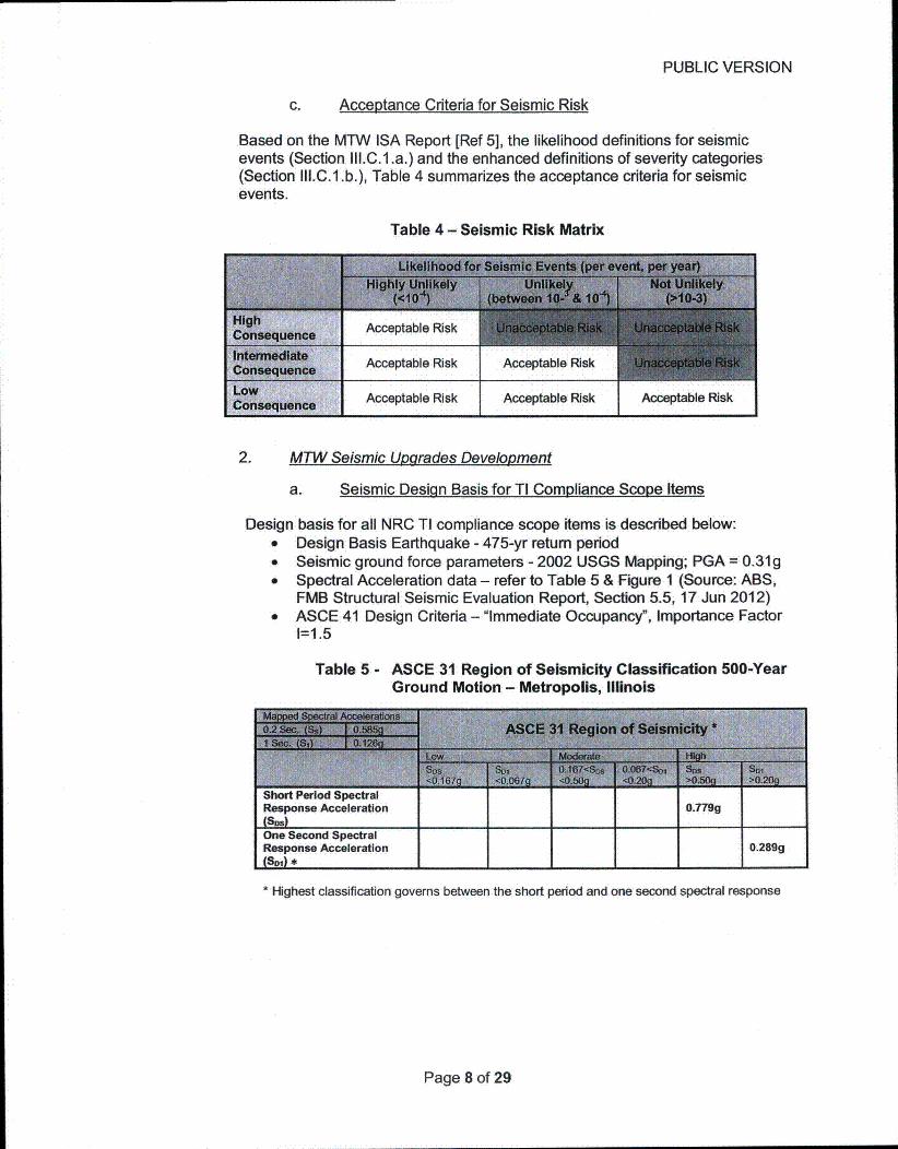
c. Acceptance Criteria for Seismic Risk
Based on the MTW ISA Report [Ref 5], the likelihood definitions for seismicevents (Section II1.C.1 .a.) and the enhanced definitions of severity categories(Section III.C.1 .b.), Table 4 summarizes the acceptance criteria for seismicevents.
Table 4 - Seismic Risk Matrix
2. MTW Seismic Utarades DeveloDment
a. Seismic Design Basis for TI Compliance Scope Items
Design basis for all NRC TI compliance scope items is described below:" Design Basis Earthquake - 475-yr retum period" Seismic ground force parameters - 2002 USGS Mapping; PGA = 0.31g" Spectral Acceleration data - refer to Table 5 & Figure 1 (Source: ABS,
FMB Structural Seismic Evaluation Report, Section 5.5, 17 Jun 2012)* ASCE 41 Design Criteria - "Immediate Occupancy", Importance Factor
1=1.5
Table 5 - ASCE 31 Region of Seismicity Classification 500-YearGround Motion - Metropolis, Illinois
Snort Period spectralResponse Acceleration 0.779g(Sna)One Second SpectralResponse Acceleration 0.289g(SM) *
* Highest classification governs between the short period and one second spectral response
Page 8 of 29

PUBLIC VERSION
2'CQ
Figure 1 - MTW Seismic SpectraMetropo lis Works Seismic Response Spýctrs
I I I I ! I I . . .. . C
_ -It
___ I I jimit 1 --
1 0P-1-1,. T (-.4.n~)
3.0
b. TI Compliance Seismic Scope Items
In 2010, MTW initiated a site-wide seismic assessment study in advance of theanticipated requirements of a new Part 40 rule. This study combined two distinctapproaches to evaluate a) seismic adequacy of existing structures, systems andcomponents (SSC) and b) conceptual modifications necessary to enhanceseismic ruggedness:
* Approach 1 involved detailed engineering analysis of SSC wheresufficient definitive design and construction documentation existed tosupport quantitative analytical and design techniques.
" Approach 2 was based on a detailed walk-down/observation of the facilityby a team consisting of a seismic capability engineer, structural/pipingengineers and knowledgeable plant staff to provide sufficient informationto determine qualitatively apparent/suspected vulnerabilities and possiblesolutions.
The assessment approach employed by SSC type analyzed is shown in Table 6below:
Table 6 - Seismic Reassessment Methodologies
Expert walk-down, qualitativeassessments, simpiffied andlordetailed stress anlyeApproach 2:Expert walk-down, limited pipestress analyses as needed
Seismic and civil/structural experts from led allactivities during the assessment study an provided required engineeringservices for development of seismic upgrade options. A detailed description of
Page 9 of 29

PUBLIC VERSION
the expert walk-down approach, methodology followed and recommendations isprovided in MTW-RPT-GEN-0008 Enercon Project Report, MTW SeismicReassessment and Upgrade, 22 Jun 2012 [Ref 9]. Note that recommendationsin this report reflect a comprehensive review of the entire MTW facility; SSCrecommendations pertaining specifically to the NRC TI findings report representa subset of this larger body of work.
To expedite correction of deficiencies as defined in the NRC TI findings report, aswell as to maintain consistency with MTW's on-going ISA effort to satisfy theanticipated new Part 40 rule, the following specific recommendations from theseismic walk-down report were selected for implementation to comply with theNRC TI Confirmatory Order. In all cases the selected improvement projects meetor exceed the current license design basis requirements such that "the plant isdesigned to withstand the 475-year earthquake with no safety implications" and"there are no design basis accidents associated with seismic events" as stated inthe current MTW ISA Report [Ref 5].
I
Page 10 of 29

PUBLIC VERSION
Page 11 of 29

PUBLIC VERSION
Page 12 of 29

PUBLIC VERSION
II
Page 13 of 29

PUBLIC VERSION
m
M:
n
n
m
m
Page 14 of 29

PUBLIC VERSION
I
I
II
II
Page 15 of 29

PUBLIC VERSION
Page 16 of 29

PUBLIC VERSION
Page 17 of 29

PUBLIC VERSION
Page 18 of 29

PUBLIC VERSION
I-.-
Page 19 of 29

PUBLIC VERSION
I
I
I
Page 20 of 29

PUBLIC VERSION
II
II
Page 21 of 29

PUBLIC VERSION
IV. MTW WIND / TORNADO EVENT SAFETY BASIS
A. Existing License Tornado Design Basis
The existing MTW ISA analysis of tornado vulnerability (refer to MTW ISA Report,Tornado, Tornado Missile and High Wind, Section 11.2 [Ref 5]) concluded that thefrequency of a direct tornado strike at MTW is < 10"/yr, thus not a credible event.However, likelihood of a tornado missile hitting the FMB or tank farm was determined tobe 1x10"6/yr, a borderline design basis event. Review of vessel wall thicknesses foundthat all tanks in the tank farm had wall thicknesses > 0.38", the critical wall thickness toprevent penetration from a design missile strike. Therefore, the conclusion drawn fromthe above analyses was that there is "no design basis accident associated with tornadosthat require a PFAP".
B. TI Findings
As detailed in the NRC TI inspection report dated 9 August 2012 [Ref 1], inspectionsduring the TI identified vulnerabilities to HF piping in the tank farm as well as liquid UF6equipment and piping in the FMB. Additionally, the method used to evaluate tornadosdid not follow guidance provided in Nureg/CR-4461.
C. Tornado Risk Mitigation
1. Definition of Risk Terms
a. LikelihoodPer Table 9, MTW's tornado risk analysis utilizes Nureg 1520Appendix A Table A-6 definitions for Likelihood which is consistentwith Likelihood definitions referenced in the existing MTW ISAReport [Ref 5].
Table 9 - Tornado Total Risk Likelihood Categories
INot Un~likelyl 3 More than 10. per event, per year
Unlikely 2 Bewe 104 andi 1n0• per event, per yearHglUniey1 Less than 10-b per event, per year~ihyUlkl
b. ConsequenceFor purposes of determining consequence severity from tornadomissile strikes, it is assumed the resulting consequence from anytornado event results in a "High Consequence" severity event.This is a conservative position and applies in all cases involvingtornado hazards.
c. Acceptance Criteria for Tornado RiskBased on the MTW ISA Report [Ref 5], the likelihood definitionsfor tornado events (Section IV.C.1 .a), and the definition of severitycategories (Section IV.C.1 .b), the following table summarizes theacceptance criteria for tornado events.
Page 22 of 29

PUBLIC VERSION
Table 10 -Tornado Risk Matrix
2. Modified Tomado Risk Analysis
MTW-CALC-GEN-005 Tornado Strike Likelihood [Ref 19] calculationswere prepared in accordance with Nureg/CR-4461 by Enercon inpreparation for meeting requirements of the anticipated new Part 40 ruleISA. Per that calculation, the frequency of tornado interactions with theMTW site was determined to be 4.4x10⁴/yr. Since this frequency exceedsthe non-credible events threshold (1 xl0-6/yr) in the MW ISA, tornadosmust be considered a credible event.
Maximum wind speed for an "unlikely" (lxI 0 5/yr frequency) tornado atMTW is calculated to be 152 mph. Missile types to be considered aremetal pipe and automobile per 10 C.F.R. § 70.61 (b)(4) guidance.
I
m
I-
Page 23 of 29

PUBLIC VERSION
I-
I
I
I
I
I
I
Page 24 of 29

PUBLIC VERSION
I
I
Page 25 of 29

PUBLIC VERSION
0
-I
U
I I
Page 26 of 29

PUBLIC VERSION
V. EMERGENCY RESPONSE PLAN
The site emergency response plan has been reviewed with respect to the NRC TemporaryInspection findings. The plan was reviewed for both seismic and wind/tornadoconsiderations. The safety margin that Honeywell has designed into the plant modificationswill support the site emergency response plan as it is currently written for protection of thepublic and site workers. Assuming all modifications are implemented, no changes to theEmergency Response Plan are needed.
The seismic improvements made to the plant, which are designed to 1.5 times the 475-yearlicense design basis to support ASCE 41 "Immediate Occupancy" design criteria, areadequately supported by the current emergency response plan. This conservative designapproach provides an assurance that no hazardous material releases will occur fromprocess equipment during a design basis earthquake event.
Improvements to the site which will harden the facility for wind/tornado activity are alsoplanned. The mitigation approach is to install protective shields as necessary. Armor (metalor composite) plates or specially designed CAT5 missile netting constructed for this purposewill be deployed to reduce missile strike risks. As with the earthquake improvements therewould be no hazardous material release from process equipment caused by missiles duringa design tornado event.
Page 27 of 29

PUBLIC VERSION
Page 28 of 29

PUBLIC VERSION
I
I
Page 29 of 29