recycling of hdpe from msw waste to 3d printing filaments
TRANSCRIPT

Förnamn Efternamn
Recycling of HDPE from MSW waste to 3D
printing filaments
Kateryna Angatkina
Degree Thesis
Materials Processing Technology
2018

DEGREE THESIS
Arcada
Degree Programme: Materials Processing Technology
Identification number: 17316
Author: Kateryna Angatkina
Title: Recycling of HDPE from MSW waste to 3D printing
filaments
Supervisor (Arcada): Maiju Holm
Commissioned by: Mirja Andersson
Abstract:
This thesis investigates the suitability of Fortum CIRCO® HDPE for fused deposition
modelling (FDM). Fortum CIRCO® HDPE is recycled high-density polyethylene sourced
from municipal solid waste, provided by Fortum Waste Solutions Oy. The literature re-
view covers rHDPE’s future in additive manufacturing. HDPE’s general ubiquity does
not carry on into 3D printing. Challenges of warping and poor first layer adhesion in FDM
are exaggerated with HDPE. The experiments are targeted towards exploring the feasi-
bility of producing a high quality rHDPE filament suitable for FDM. Filament character-
ization techniques are used to compare rHDPE filament to a reference HDPE material.
Also, printed parts are tensile tested to analyse mechanical properties of rHDPE and
HDPE. This thesis illustrates that it is possible to produce rHDPE filament, although ex-
trusion parameters have not been fully optimized. During the extrusion process a heated
water bath was found to be crucial in producing the most round and the most regular
filament. rHDPE filament has a more elliptical shape and greater diameter variation than
pristine HDPE when produced with the available setup. Both recycled and pristine fila-
ment samples produced comparable print quality and similar Young’s Modulus values
during tensile testing. In addition, the recycled material exhibited higher yield strength
and greater ductility. rHDPE has potential as a feedstock material for FDM. Further re-
search is required to improve the extrusion process.
Keywords: rHDPE, FDM, 3D printing, filament, CIRCO® HDPE, MSW
Number of pages: 48
Language: English
Date of acceptance:

CONTENTS
1 INTRODUCTION ................................................................................................... 9
1.1 Background ................................................................................................................... 9
1.2 Aim and objectives ...................................................................................................... 10
2 LITERATURE REVIEW ....................................................................................... 11
2.1 3D printing ................................................................................................................... 11
2.1.1 A brief history of 3D printing ................................................................................ 11
2.1.2 3D printing technology ......................................................................................... 11
2.1.3 FDM ..................................................................................................................... 12
2.1.4 Filament requirements ......................................................................................... 13
2.1.5 3D printing bed surface ....................................................................................... 14
2.2 Plastics ........................................................................................................................ 15
2.2.1 Commonly used materials for FDM printing ........................................................ 16
2.2.2 High-Density Polyethylene .................................................................................. 17
2.2.3 Challenges of HDPE in FDM ............................................................................... 19
2.2.4 rHDPE from MSW in FDM ................................................................................... 21
2.2.5 CIRCO® recycled HDPE ...................................................................................... 22
2.3 Filament manufacturing ............................................................................................... 23
2.3.1 Extrusion .............................................................................................................. 23
2.3.2 Filament characterization techniques .................................................................. 26
3 METHODS ........................................................................................................... 30
3.1 Materials and equipment ............................................................................................. 30
3.1.1 Materials .............................................................................................................. 30
3.1.2 Equipment ........................................................................................................... 30
3.2 Filament manufacturing ............................................................................................... 30
3.3 Testing ......................................................................................................................... 32
3.3.1 Filament quality control........................................................................................ 32
3.3.2 Melt Flow Rate ..................................................................................................... 33
3.3.3 Tensile testing of raw materials ........................................................................... 34
3.3.4 Tensile testing of 3D printed models ................................................................... 35
3.3.5 The rHDPE filament prototype testing ................................................................. 37
4 RESULTS ............................................................................................................ 38
4.1 Filament extrusion ....................................................................................................... 38
4.2 Filament roundness ..................................................................................................... 39
4.3 Porosity and impurities ................................................................................................ 40
4.4 Melt Flow Rate ............................................................................................................. 42

4.5 Tensile testing ............................................................................................................. 42
4.6 3D printing ................................................................................................................... 44
5 DISCUSSION ...................................................................................................... 45
6 CONCLUSION..................................................................................................... 47
REFERENCES ........................................................................................................... 48
APPENDIX I ............................................................................................................... 53
APPENDIX II .............................................................................................................. 55
APPENDIX III ............................................................................................................. 56

Figures
Figure 1. Two main branches of 3D printing technology [7] ......................................... 12
Figure 2. FDM printer process [9] .................................................................................. 13
Figure 3. Failures of the gripping mechanism of the printer [10] .................................. 14
Figure 4. Monomer vs. Polymer [13] ............................................................................. 15
Figure 5. Thermoplastic vs. Thermoset [13] .................................................................. 15
Figure 6. Amorphous (a) and semi-crystalline (b) structural representation [14] .......... 16
Figure 7. Schematics of molecules of HDPE and LDPE [19] ........................................ 18
Figure 8. Contact angle measurement (θ) of wettability of material [23] ...................... 20
Figure 9. HDPE recycling code [26] .............................................................................. 21
Figure 10. Schematics of a single screw extruder [30]................................................... 23
Figure 11. Geometry of the extruder screw [30] ............................................................ 24
Figure 12. Typical tensile specimen [34] ....................................................................... 27
Figure 13. Stress - strain curve for polymers [33] .......................................................... 28
Figure 14. Schematic of MFR basic test, ISO 1133 [36] ............................................... 29
Figure 15. KFM extruder, Arcada 2018 ......................................................................... 31
Figure 16. Puller and cooling water bath, Arcada 2018 ................................................. 31
Figure 17. Water bath dam entrance, Arcada 2018 ........................................................ 31
Figure 18. Schematic of filament cross section .............................................................. 32
Figure 19. Measurement of the diameter of the filament at interval of 1 m ................... 32
Figure 20. Material testing machine, M 350-5CT Testometric, Arcada 2018 ............... 33
Figure 21. Dumbbell sample type IV according to ASTM D638 Standard [41]............ 34
Figure 22. Material testing machine, Testometric M 350- 5CT, Arcada 2018 .............. 35
Figure 23. miniFactory printer, Arcada 2018 ................................................................. 35
Figure 24. Tensile test specimen type 1BA, SFS EN ISO 527-2:1996[41] ................... 36
Figure 25. Sliced model of the specimen type 1BA, SFS EN ISO 527-2:1996 ............. 36
Figure 26. Specimen layer arrangement for a tensile test [42] ....................................... 37
Figure 27. Sliced models of a hollow cub and cylinder for 3D printing ........................ 38
Figure 28. Produced filament from rHDPE .................................................................... 39
Figure 29. rHDPE and pristine HDPE averaged filament diameter over distance ......... 40
Figure 30. Impurities of rHDPE filament ....................................................................... 40
Figure 31. The surface of rHDPE and pristine HDPE filament ..................................... 41
Figure 32. The cross section of rHDPE and pristine HDPE filament ............................ 41
Figure 33. DSC curves for unidentified foreign material extracted from rHDPE filament
........................................................................................................................................ 42
Figure 34. Printed tensile specimens of rHDPE and pristine HDPE (from left to right) 43
Figure 35. Warping of the rHDPE tensile sample .......................................................... 44
Figure 36. Warping of rHDPE and HDPE cube models ................................................ 44
Figure 37. Warping results of the hollow cubes and cylinders samples......................... 44
Figure 38. rHDPE printed samples of hollow cube and cylinder ................................... 45
Tables
Table 1. Common 3D printing bed materials [12].......................................................... 14
Table 2. Advantages and disadvantages of various thermoplastic used in FDM [6]. .... 17
Table 3. Problems of rHDPE from MSW [2] ................................................................. 22
Table 4. The physical and mechanical properties of rHDPE (by Fortum CIRCO®) [29]
........................................................................................................................................ 23
Table 5. MFR of the most common commercial filaments ............................................ 29
Table 6. Temperature of various extruders’ zones of rHDPE and pristine HDPE ......... 32
Table 7. Extrusion process parameters for rHDPE and pristine HDPE ......................... 32
Table 8. Parameters for injection moulding machine ..................................................... 34
Table 9. The miniFactory printer setting for rHDPE and pristine HDPE tensile specimens
........................................................................................................................................ 37
Table 10. Diameter values of pristine HDPE and rHDPE filaments .............................. 39
Table 11. MFR results of the rHDPE and pristine HDPE filaments .............................. 42
Table 12. Tensile test results of injection moulding of rHDPE and pristine HDPE samples
........................................................................................................................................ 43
Table 13. Tensile test results of printed rHDPE and pristine HDPE samples ................ 43

ABBREVIATION
3D Three dimensional
ABS Acrylonitrile butadiene styrene
AM Additive manufacturing
CAD Computer-aided drafting
FDM Fused deposition modelling
HDPE High density polyethylene
MFR Melt flow rate
MSW Municipal solid waste
PLA Polylactic acid
rHDPE Recycled high density polyethylene
STL Stereolithography

FOREWORD
I would like to express my gratitude to my supervisor Maiju Holm for her professional
advices, supervision and support throughout this thesis.
I would also like to thank my professor Mirja Andersson who introduced me to this in-
teresting project and company Fortum Waste Solutions Oy (previously Ekokem) who
provided this work with recycled HDPE.
Lastly, I would like to thank you my friends and family for their support and encourage-
ment.
Helsinki, 2018
Kateryna Angatkina

9
1 INTRODUCTION
1.1 Background
Global production of plastic is increasing year by year. Plastic waste is not only generat-
ing huge numbers of landfills but also polluting oceans [1]. Most plastic materials are not
decomposable and release harmful toxins when burnt. A variety of solid waste manage-
ment techniques emerged, and plastic recycling became the most effective solution to
protect the environment and reduce use of natural resources [2].
HDPE is the most produced plastic in the world with a wide range of applications. Do-
mestic trash contains a large amount of plastic waste because of its widespread use in
plastic packaging. Generally, plastic municipal solid waste is difficult to recycle due to
other solid waste mixed with plastics. Production of high quality recycled HDPE requires
complex and costly separation steps [2].
3D printing is one of the most promising technologies of the 21st century. A wide range
of 3D printers are used for professional and consumer applications. They can fabricate
complex three-dimensional objects from children's toys to fossil models [3].
HDPE has good chemical resistance and low water absorption. It is a non-toxic material
with excellent mechanicals properties [4]. HDPE is not popular in 3D printing since it is
a challenging material to work with, unlike PLA and ABS which are very common ther-
moplastics in FDM printing [5].
Only recently has rHDPE been considered as a feedstock for 3D printing [6]. The intro-
duction of rHDPE into the 3D printing community will be another step in solid waste
minimization as HDPE is the majority of municipal solid waste [5].

10
1.2 Aim and objectives
The aim of this research is to determine the suitability of rHDPE sourced from MSW for
3D printing.
Objectives:
• Uncover 3D printing challenges of HDPE in FDM printing
• Compare the material properties CIRCO® rHDPE to pristine HDPE
• Produce by extrusion 3D printing filament from CIRCO® rHDPE
• Evaluate produced CIRCO® rHDPE filament

11
2 LITERATURE REVIEW
2.1 3D printing
2.1.1 A brief history of 3D printing
3D printing or additive manufacturing (AM) technology has been around since the begin-
ning of the new millennium. In 1984, Charles Hull developed an apparatus for creating
three-dimensional objects from layers of cured liquid photopolymer by exposer to UV
light. Two years later this technique was patented and called “stereolithography” [3]. 3D
Systems which was started by Charles Hull developed the first 3D printer for commercial
use, SLA-250 [3].
By the end of 1988, 3D printing technology had gained more recognition. At the Univer-
sity of Texas, Dr. Carl Deckard and Dr. Joe Beaman developed selective laser sintering
(SLS) which was a fundamentally different way of three-dimensional printing by using
powder instead of liquid material [6].
Scott Crump, the founder of Stratasys, invented Fused Deposition Modelling (FDM) and
the first commercial device based on FDM technology appeared in 1991 [6]. Solidscape
started serial production of 3D inkjet printers at an affordable price, in 1993. The first
colour 3D printer, Spectrum Z510, appeared in 2005 and it was developed by ZCorpora-
tion [6].
2.1.2 3D printing technology
There are two main branches of 3D printing technology which are selective deposition
printers and selective binding printers, see Figure 1. The basic principle of selective dep-
osition printers is the deposition of raw material into layers by squeezing out soft material
through a print nozzle. Selective binding printers binds material with help of heat or light
by using powder or a light sensitive photopolymer as a feedstock material [3].

12
The basic printing process consists of three central phases: creation of a 3D model, use
of printer software to slice the model and finally model fabrication. A model of the part
is created by computer-aided design software. The CAD model of the design is converted
into an STL file. The printer software calculates the mechanical paths of the print nozzle
by slicing the STL file into 2D sectional layers [6].
Figure 1. Two main branches of 3D printing technology [7]
2.1.3 FDM
In an FDM printer, feedstock as filament is fed from a spool through an extrusion nozzle.
The nozzle has a heater block which melts a thermoplastic polymer. The melted material
is extruded onto the printer build platform as shown in Figure 2. The flow and temperature
of a material are set in printer software [8].
Most FDM printers deposit material by moving the print head or the platform along a set
of horizontal and vertical axis while tracing the calculated path of the 2D layer. The first
layer of the printed material usually outlines the base of the model. After the first layer’s
contours are filled, the print nozzle is raised a set layer height and continues to lay down
the second layer. The printer lays down one cross-section of the model after another until
the model is finished [3].

13
Figure 2. FDM printer process [9]
2.1.4 Filament requirements
A high-quality filament has a constant diameter across the entire length of the spool. Dur-
ing manufacturing filament diameter variation is inevitable. A diameter tolerance of ±
0.05 mm is considered as a standard for 1.75 mm nominal filament diameter. Inconsistent
performance or a failed print is usually caused by irregular diameter of the filament [10].
Undersized filament can cause backflow inside the heater block of the extruder as shown
in Figure 3.
Filament diameter dimensions affect the functionality of the extruder’s gripping mecha-
nism. The drive gears of the extruder grip the filament and push it forward into the heated
nozzle. Grip failure can occur with underside or oversized filament. Too thin a filament
cannot be griped properly by the extruder drive gears and pushed forward inside the print
nozzle. Too wide and the filament simply will not fit into the nozzle opening or it can
strip some plastic off the surface by the drive gears leaving nothing to grip on to. In all
cases no material is extruded out of the extruder’s nozzle and the printing process halts
[10, 11].
The roundness of the filament also plays a significant role in good printing performance.
Elliptical filament can cause similar failures of the gripping mechanism as filament di-
ameter irregularity [10].

14
Figure 3. Failures of the gripping mechanism of the printer [10]
2.1.5 3D printing bed surface
The print bed is a surface where material is deposited onto by the extruder nozzle. There
are both retaining and releasing properties required from a bed material. To create suc-
cessfully printed parts, the first layer of the filament must stick to the print bed material.
Good adhesion of the first layer prevents the printed part from moving around and allows
for an aligned second layer. Warping is also a concern with poor adhesion of the first
layer. Excessive warping causes dimensional errors as well as possible complete delami-
nation from the bed. Finally, the printed part and the bed material must separate without
damaging each other [10].
Common 3D printing bed materials are shown in Table 1.
Table 1. Common 3D printing bed materials [12]
Material Print bed surface
PLA Blue painter's tape, heated glass
ABS Kapton tape, hair spray
ABS slurry (mixture of ABS and acetone)
Nylon Garolite (fiberglass/epoxy laminate)

15
2.2 Plastics
Plastic is made up of synthetic or natural polymers (resins). Polymers are long chains of
monomers. A monomer is a main base molecule that repeats throughout the polymer
structure, see Figure 4. Polymers can be synthesized by polymerization or polycondensa-
tion of monomers in the presence of catalysts under strictly defined temperature condi-
tions and pressures [13].
Figure 4. Monomer vs. Polymer [13]
Plastics can be divided into two groups: thermoplastics and thermosets. Thermoplastics
are capable of reprocessing by remelting when heated and solidifying upon cooling. Un-
like thermosets which have an irreversible curing process hence thermosets cannot be
remelted and reused [2]. Thermoplastics consist of long independent polymers chains
that are linked together by intermolecular interactions force. Thermosets are composed
of chemically crosslinked polymer chains, and therefore they cannot be reshaped upon
cooling as thermoplastics, see Figure 5 [13].
Figure 5. Thermoplastic vs. Thermoset [13]
16
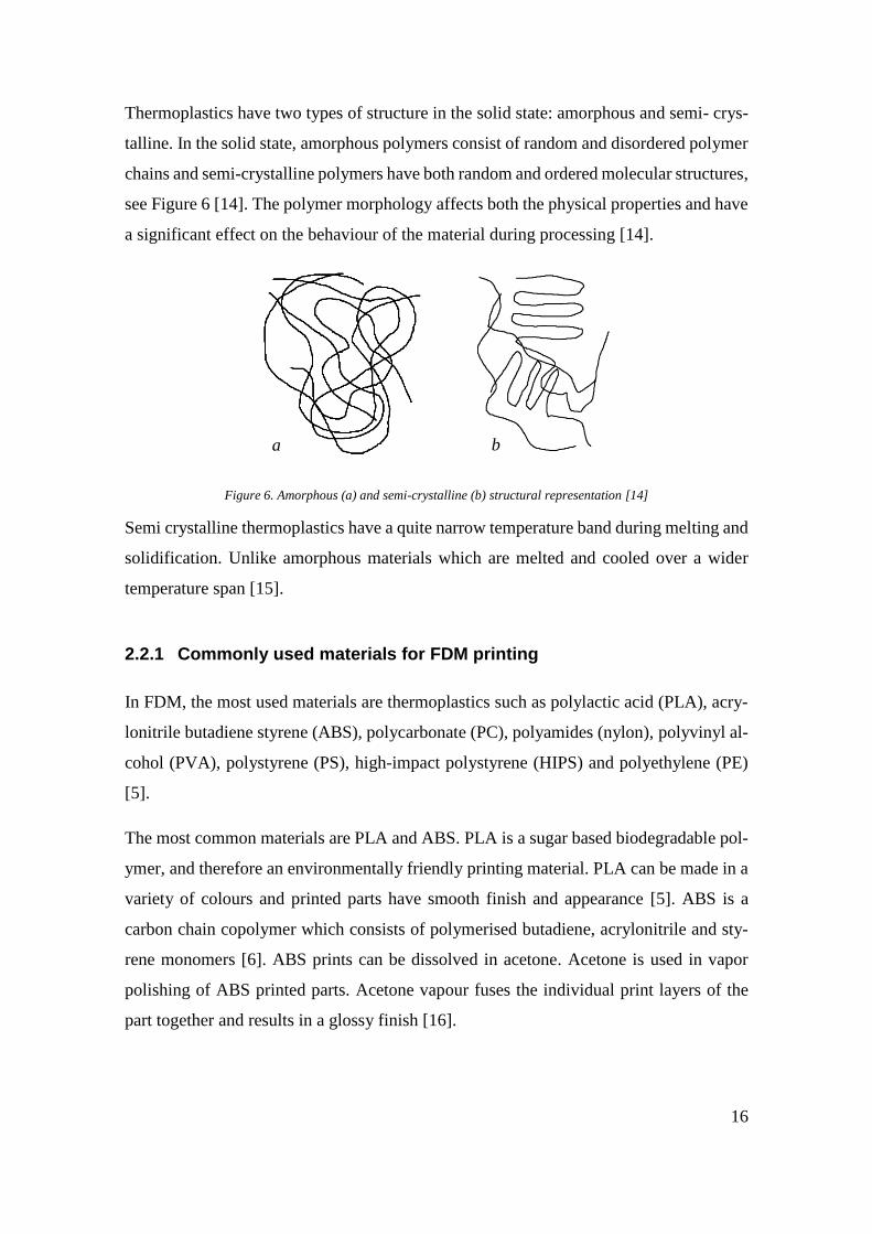
Thermoplastics have two types of structure in the solid state: amorphous and semi- crys-
talline. In the solid state, amorphous polymers consist of random and disordered polymer
chains and semi-crystalline polymers have both random and ordered molecular structures,
see Figure 6 [14]. The polymer morphology affects both the physical properties and have
a significant effect on the behaviour of the material during processing [14].
Figure 6. Amorphous (a) and semi-crystalline (b) structural representation [14]
Semi crystalline thermoplastics have a quite narrow temperature band during melting and
solidification. Unlike amorphous materials which are melted and cooled over a wider
temperature span [15].
2.2.1 Commonly used materials for FDM printing
In FDM, the most used materials are thermoplastics such as polylactic acid (PLA), acry-
lonitrile butadiene styrene (ABS), polycarbonate (PC), polyamides (nylon), polyvinyl al-
cohol (PVA), polystyrene (PS), high-impact polystyrene (HIPS) and polyethylene (PE)
[5].
The most common materials are PLA and ABS. PLA is a sugar based biodegradable pol-
ymer, and therefore an environmentally friendly printing material. PLA can be made in a
variety of colours and printed parts have smooth finish and appearance [5]. ABS is a
carbon chain copolymer which consists of polymerised butadiene, acrylonitrile and sty-
rene monomers [6]. ABS prints can be dissolved in acetone. Acetone is used in vapor
polishing of ABS printed parts. Acetone vapour fuses the individual print layers of the
part together and results in a glossy finish [16].
a b

17
Polycarbonate (PC) is synthesized by a condensation polymerization of bisphenol A and
phosgene. PC has a high gloss and clarity. Nylon is made by the reaction of the monomers
diamine and a dicarboxylic acid. Nylon is strong, durable and flexible material. Polysty-
rene is made from the monomer styrene by free radical vinyl polymerization. PS is inex-
pensive, rigid and the second most used plastic in the world. PVA and HIPS are used
mainly as soluble support materials. PVA is polyvinyl acetate and water soluble. HIPS is
a limonene soluble polymer [5].
Advantages and disadvantages of various thermoplastic used in FDM are summarized in
Table 2.
Table 2. Advantages and disadvantages of various thermoplastic used in FDM [6].
2.2.2 High-Density Polyethylene
Polyethylene is a thermoplastic polymer which consists of a long chain of repeating meth-
ylene -(CH2)- groups [17]:
−𝐶𝐻2 − 𝐶𝐻2 − 𝐶𝐻2 − 𝐶𝐻2 − 𝐶𝐻2 −

18
Polyethylene is formed by the process of additional polymerization. A monomer, eth-
ylene, with a double bond is linked together with other similar monomers without pro-
ducing a side product such as water. The repeating units of addition polymers have the
same chemical composition as the monomers [17]:
𝑛𝐶𝐻2 = 𝐶𝐻2 → ~(𝐶𝐻2 − 𝐶𝐻2)𝑛~
Ethylene Polyethylene
High density polyethylene (HDPE) is a linear polymer and formed by the Ziegler-Natta
process. HDPE has a density range between 0.94-0.96 g/cm 3 and low-density polyeth-
ylene (LDPE) has the density 0.915 to 0.930 g/cm 3. The high density of HDPE is due to
molecules with little or no branching unlike LDPE which has some long branches and
many short branches, see Figure 7 [18].
Figure 7. Schematics of molecules of HDPE and LDPE [19]
HDPE is semi-crystalline polymer with small amorphous regions [15]. HDPE has high
crystallinity between 60 and 80% in a solid state and therefore shows high tensile strength
[18, 20]. HDPE, as a semi-crystalline thermoplastic, has higher shrinkage values than
amorphous plastics between solidifying and transition temperatures [15].
HDPE is used in injection moulding, extrusion, rotational moulding and thermoforming
manufacturing processes [4].
Typical characteristics of HDPE [4, 15]:
• Toughness and stiffness
• Cold resistant
• Practically indestructible, but brittle after prolonged UV exposure
19
• No water absorption
• Very low dielectric losses
• High chemical resistance (insoluble in all solvents)
• Good barrier properties against gases and vapours
• High shrinkage
2.2.3 Challenges of HDPE in FDM
Warping and shrinkage of HDPE in FDM printing
HDPE is a semi-crystalline polymer and contains both amorphous and crystalline regions
within the same polymer matrix. Semi-crystalline materials are prone to higher shrinkage
during melt to solid transition than amorphous materials. The shrinkage is higher in semi
crystalline materials due to its crystalline regions, the ordered and aligned molecular
chains take up less space than the disordered polymer chains in amorphous region. Upon
cooling, semi crystalline plastic’s volume continues to decrease as the molecular chains
are very closely aligning, packing themselves in their crystalline formation [14, 15].
HDPE shows a high shrinkage due to its higher crystallinity which makes it very sensitive
to differential cooling rates. HDPE shrinkage rate is 4-6% therefore the rate of cooling is
crucial for FDM process. To prevent 3D printed part of HDPE from warping, the layers
of filament need be slowly cooled down during printing. The shrinkage between the melt
and solid state is important [21].
The shrinkage resultant warping of the part being printed increases at faster cooling rates.
The cooling time of 3D printed part is dependent on the wall thickness, melt temperature
and rate of crystallization. The thin sections of mid-print part are cooled more rapidly
than thick sections and consequently shrinkage in the former will be greater, causing the
whole part to warp from differential cooling and shrinkage [21].
In HDPE deposition, a heated enclosure system for the 3D printer can be beneficial in
controlling the shrinkage and warpage of the printed parts. The use of infrared (IR) lamps
to heat and control the temperature of a printed part during printing can bring very positive
results [22].

20
Adhesion and bonding of HDPE
In FDM, adhesion and bonding of the filament is a key element to good printability of the
material [23]. HDPE poor adhesion results from low surface free energy, low polarity,
and it lack functional groups on the surface [24].
Wetting is important in the adhesion of two materials and it can be used to determine the
surface energy of a material. Wettability is a measurement of a contact angle (θ) between
a solid and liquid. Contact angle (θ) is the tangent angle formed by a drop of liquid which
is placed on a substrate surface, see Figure 8 [23].
When the angle is θ > 90 °, the attraction between liquid and solid is poor. A good wetting
has a strong attraction between the liquid and the solid, when the angle is θ < 90 ° [23].
Figure 8. Contact angle measurement (θ) of wettability of material [23]
In general, HDPE has the water contact angle around 104 ° which means that the material
has no polarity within its molecules, hence low surface energy. HDPE has adhesion prob-
lems due to weak boundary layers, therefore wettability is a crucial importance to the
solution [23].
HDPE’s poor wetting properties require to be bonded quickly before the molten material
solidifies. The surfaces of the HDPE need to be warmed up prior to adhesive application
to avoid the formation of poorly wetting surfaces which will lead to weaker bonding [25].
HDPE filaments needs to be applied the bed at a temperature significantly higher than the
basic melting temperature of the HDPE filament to produce a lower viscosity fluid that
successfully wets bed surface [25]. HDPE wetting properties can be improved by intro-
ducing polar groups into the material or increasing surface energy. It will lead to im-
proved adhesion by providing fewer weak boundary layers through better wetting [23].
θ > 90 °
θ < 90 °
low surface energy high surface energy

21
HDPE filament exhibits rather good self-bonding since the diffusion between two sur-
faces of HDPE filament at a high temperature occurs without complications [23].
Printed layers of HDPE bind easily to each other during the printing process. Since HDPE
has difficulties binding to other materials an appropriate build surface must be used [5].
2.2.4 rHDPE from MSW in FDM
HDPE is a reusable thermoplastic polymer with the recycling code «2» as shown in Figure
9. In general, thermoplastics can be reprocessed many times by melting and solidifying
into new products. Unlike thermosetting polymers waste which are transformed into fuels
or chemicals and cannot be directly reused as a recycled material [2].
Figure 9. HDPE recycling code [26]
rHDPE from MSW was introduced into the consumption cycle as a material for secondary
applications due to its inferiority to virgin HDPE. But even as a recycled material, HDPE
still possesses unique characteristics such as water and chemical resistance, moderate im-
pact and tensile strength, and excellent abrasion-resistant [21].
In MSW, HDPE is mixed with solids and other plastics. A recycling schema to obtain a
homogeneous composition stream of HDPE from plastic waste is complex and costly [2].
In this research, rHDPE from MSW was reprocessed by using a mechanical recycling
approach which involves several steps such as collecting, separating, grinding, washing,
drying and re-granulating [2].

22
rHDPE from MSW has three major problems see Table 3.
Table 3. Problems of rHDPE from MSW [2]
Contaminants small amounts of a different types of plastics may change the proper-
ties of the bulk material (HDPE)
Additives
plasticizers, substances, stabilizers and colouring. The recycled plas-
tic usually has a grey colour because of the colour variety of the
waste products.
Degradation
recycled plastics show worse mechanicals properties than the pristine
material due to prolonged exposure to temperature, ultraviolet radia-
tion, oxygen and ozone
Research related to rHDPE for additive manufacturing is scarce. Nevertheless, the acces-
sibility of HDPE waste generates a great deal of interest among 3D printing enthusiasts
and encourages efforts to apply recycled materials for good use. Especially milk jugs as
a rHDPE material were adapted to 3D printing in numerous recycling research projects
[5].
2.2.5 CIRCO® recycled HDPE
rHDPE was provided by Fortum Waste Solutions Oy formerly known as Ekokem. Fortum
is a clean-energy company which is located in Finland. Fortum’s mission is to engage
customers and society to drive the change towards a cleaner world [27]. Fortum Recy-
cling and Waste Solutions unit offers material efficiency improvement in the Nordic
countries [27].
The batched of rHDPE used in this paper was recycled from MSW which was refined in
the Plastic Refinery at the Riihimäki Circular Economy Village, Finland. rHDPE was
returned manly to be used as an industrial material [28].
The physical and mechanical properties of Fortum CIRCO® recycled HDPE are shown
in Table 4 below.

23
Table 4. The physical and mechanical properties of rHDPE (by Fortum CIRCO®) [29]
Property Value
Color Grey
Density at 23 °C 947 kg/m3
MFI 2,16 kg/190 °C 0,35 g/10min
Tensile strength at break MD 10,7 MPa
Elongation at yield MD 39%
Tensile strength at yield MD 24,8 MPa
Young’s Modulus 376 MPa
Impact strength 115 kJ/m2
2.3 Filament manufacturing
2.3.1 Extrusion
Extrusion is a manufacturing process of homogenization of a raw material into a uni-
form shape product by squeezing it through a die. It is a continuous operation where the
raw material in the form of pellets are fed through a hopper into the heated barrel of the
extruder. In the barrel, the pellets are melted, blended and compressed through a die, see
Figure 10 [4].
Figure 10. Schematics of a single screw extruder [30]

24
In the extruder, the most important component is the screw-barrel system since the mate-
rial is melted and processed from the barrel temperature and mechanical energy which is
imparted from the screw rotation [31].
The screw barrel system is divided into three sections [31] as shown in Figure 10 above:
• Feed section, where the raw material in the pellet form is compacted together
• Compression section, where the melted material is sheared by the screw flights
and as the screw channel depth gradually gets shallower, see Figure 11.
• Metering section, where all the polymer is molten, and the screw channel depth is
constant
Figure 11. Geometry of the extruder screw [30]
Screw
In manufacturing industry, the screw differs with respect to materials since the efficiency
of the extrusion process is mostly determined by the screw design. In the barrel the poly-
mer is stretched and sheared with the heated walls by the screw flights with each screw
turn. Frictional heating from the screw rotation and conduction heat from the barrel walls
are both contributed to polymer melting. The processing material is constantly pushed
from the feed section to the metering section by the screw. But the melt cannot be con-
veyed to a die if the molten polymer is stuck to the screw and not to the barrel walls [4,
31].
Die
The extruder die’s function is to shape the melted material into a desired cross-sectional
profile. The molecular orientation and surface aesthetics of a product can be also con-
trolled by die design. High molecular orientation can be beneficial by increasing tensile
25
performance or it can cause the polymer to shrink, warp and even easily split in the ma-
chine direction [14].
Die swell
At the die exit, polymer materials tend to swell due to expansion of viscoelastic fluids.
The elastic recovery occurs when elastic stresses contract and relax in the fluid during
extrusion process. For example, PE increases in size by 15-20% relative to die cross-
sectional area [14]. Die swell is dependent on shear stress, polymer molecular weight
distribution and geometric dimensions of the screw and die such as the length to diameter
ratio of the die [4]. To achieve a desired shape of the product extrudate is pulled away
from the die and drawn down to its final dimensions by a puller. The draw speed depends
on the product size exiting the die versus the size required in the final product application
[14].
Cooling
Controlled cooling is important in production of final products for satisfactory dimen-
sions and performance. The extrudate is commonly cooled with water or air. At first the
cooling extrudate forms surface skin while the centre stays molten. To prevent warpage
of the part it is necessary to cool uniformly on all sides preferably at a slow speed. Water
cooling systems allow the extrusion line to operate at higher rates. For semi-crystalline
polymers the extrudate needs to be cooled slowly and evenly for precise product dimen-
sions [14].
Puller
Final dimensions of the product are controlled by the extruder screw speed, cooling strat-
egy and the puller speed. The draw and tension of the extrudate are regulated by the puller.
Changes in the product dimensions are usually caused by periodic variations in the puller
speed or extruder output. The extruder output rate and the puller speed must match each
other. The puller can cause marks on the final product’s surface by applying too much
pressure with the puller rolls. For good performance the puller must be properly aligned
with extruder at an appropriate distance [14].

26
2.3.2 Filament characterization techniques
There are limited standards which relate to AM. Filament based standards for AM are
very general leaving no guidelines. Most of material descriptions and processes involved
in their fabrication are unavailable due to copyrights or formula secrets in AM business
[32].
Generally tested properties of FDM filaments are [32]:
• Filament diameter consistency
• Porosity
• Moisture content
• Thermal properties
• Mechanical properties of filament
• Melt Flow Rate
Filament Diameter Consistency
A 3D printed part’s layers thickness and the extrusion diameter are determent by the noz-
zle diameter which is generally fixed in a FDM printer. A common commercial filament
has an average diameter of 1.75 mm or 3 mm. A nonuniformity in diameter leads to im-
proper feeding or jamming of feedstock and even nozzle clogging. Deviation in the di-
ameter is inevitable in the actual manufacturing process [32].
Porosity
Porosity is determined by void content percentage in the filament. High void percentage
of the filament can cause a great deviation in mechanical properties. The void content of
filament can also be used to identify quality of the filament [32].
Moisture content
Moisture content influences the melt viscosity. High moisture content of the filament
negatively affects print quality. 3D printing materials with low moisture content usually
produce better quality prints. Inside the hot print nozzle, moisture in the filament vapor-
izes and leaves gaps in the strand of filament. Gaps can have a negative result on inter
layer adhesion. For example, Nylon, PC and ABS are hydroscopic materials and a

27
standard test method for determination of moisture in plastics by loss in weight, ASTM
D6980, can be used to find the moisture content these thermoplastics [6, 32].
Thermal Properties
Melting points and glass-transition temperatures of polymers are studied to determine the
thermal stability of the thermoplastics. In FDM the printing temperature of the material
above the melting point of polymer and at high temperatures thermoplastics degrade.
Differential scanning calorimetry (DSC) is used to study thermal degradation [32].
Mechanical properties of material
The most relevant mechanical properties of material processability in FDM are the tensile
strength and strain. The mechanical properties of recycled polymers can considerably
vary with impurities in their structure. The material properties of strength, ductility and
toughness can be affected [32].
Tensile properties predict how the material will react to forces being applied in tension.
Tensile tests show the ability of a material to withstand maximum load before rupture
[33]. A tensile test of plastics consists of loading a specimen in tension. The test provides
data of the tensile stress-strain relationship [34]. A typical tensile specimen is illustrated
in Figure 12.
Figure 12. Typical tensile specimen [34]
The tensile stress-strain relationship is the ratio of the applied force (F) over cross sec-
tional area of the gage section (A) at a constant deformation rate [32]:
𝛿 =𝐹
𝐴
Where 𝛿 is the stress [MPa], F is force [N] and A is cross sectional area [mm2]

28
The definition of strain is:
휀 =∆𝐿
𝐿0
Where 휀 is the strain, ∆𝐿 is the extension of the length [mm] and L0 is the original length
[mm].
Young’s Modulus, the elastic modulus, is a measure of the stiffness of the material. It is
defined as the relationship between the stress and strain in an elastic material:
𝐸 =𝛿
휀
Where E is the modulus [MPa], 𝛿 is the stress [MPa] and 휀 is the strain [32].
A typical stress-strain relationship for a polymer material with a yield stress greater than
the failure stress is shown in Figure 13. Characteristic values associated with the material
under test can be determined [33]:
• Stress at Yield (MPa)
The lowest stress at which strain increases without a corresponding increase in
stress.
• Stress at Break (MPa)
The tensile strength of the material at failure.
• Strain at Yield (%)
The corresponding tensile strain of the material at the yield stress.
• Strain at Break (%)
The corresponding tensile strain of the material at the failure stress.
Figure 13. Stress - strain curve for polymers [33]

29
Melt Flow Rate
In FDM, the molten polymer is extruded through the print nozzle. Polymers that are not
viscous enough or less viscous can be difficult to deposit. Melt flow rate (MFR) tests are
done to determine the flow characteristics of material [32]. MFR is the number of grams
of material extruded from a die in a certain time under a certain applied load [35]. A
schematic of MFR basic test is illustrated in Figure 14 according to ISO 1133:2005 [35].
Figure 14. Schematic of MFR basic test, ISO 1133 [36]
MFR values are not directly comparable since the weight used to drive the MFR grader
piston the temperature can be different. The most common commercial filaments have a
high melt flow rate indicating low viscosity [35], see Table 5.
Table 5. MFR of the most common commercial filaments
Material MFR [g/10 min]
ABS (220°C/10.0 kg) 0.49 to 36 [37]
PLA (190°C/2.16 kg) 1.5 to 36 [38]
PC (260°C/5.0 kg) 11 to 29 [39]
HIPS (200°C/5.0 kg) 3,0 to 12 [40]

30
3 METHODS
3.1 Materials and equipment
3.1.1 Materials
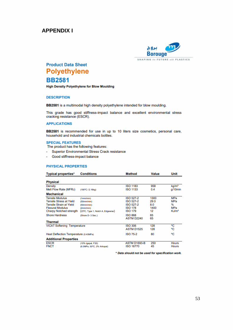
The following materials were used in this research: recycled high-density polyethylene
(rHDPE), CIRCO®, supplied by Fortum Waste Solution Oy, MFR 0,35 g/10min. (190
°C/2.16 kg); high-density polyethylene (HDPE), supplied by Borouge, MFR 0.4 g/10
min. (190 °C/2.16kg).
HDPE from Borouge was used as a reference material to analyse mechanical and flow
properties of rHDPE in relation to pristine HDPE.
3.1.2 Equipment
Equipment available at the Arcada’s production laboratory were used in this research:
• A single screw Eco Ex model extruder made by KFM
• Extrusion plastometer, Mitaten MEP 2/PC
• Injection moulding machine, ES 200/25HL CC88, made by ENGEL
• Material testing machine, M 350-5CT, made by Testometric
• FDM printer made by miniFactory
3.2 Filament manufacturing
rHDPE and reference HDPE were provided in pellet form. The material granules were
fed into the extruder hopper where they were heated to molten state and forced through
the die producing filament. Both materials were not pre-dried before extrusion process.
Filament extrusion line consisted of a single screw Eco Ex model extruder, cold air gun
set up to cool and support extrudate in the air, a water bath and a pulling unit with a
coiling device, see Figure 15 and 16. A 3 mm circular die was used to achieve 1.75 mm
diameter of the filament by drawing to final diameter. The water cooling section had a

31
length of 75 cm and was position at 10 cm from the extruder die. The filament puller was
position at 175 cm from the extruder die.
Figure 15. KFM extruder, Arcada 2018
Figure 16. Puller and cooling water bath, Arcada 2018
The extrusion process parameters for rHDPE were selected based off the results of several
trial runs. The same parameters were used for pristine HDPE extrusion see Table 6 and
Table 7. The water bath temperature was set to 50 °C to have a slow cooling process and
to control diameters of filaments. The cooling water temperature was crucial to the round-
ness and diameter tolerance of the filament. To cool the extrudate uniformly on all sided,
it was positioned at 90 ° at the water bath dam entrance see Figure 17.
Figure 17. Water bath dam entrance, Arcada 2018
32
Table 6. Temperature of various extruders’ zones of rHDPE and pristine HDPE
Die Zone 4 Zone 3 Zone 2 Zone 1
200 °C 195 °C 190 °C 180 °C 180 °C
Table 7. Extrusion process parameters for rHDPE and pristine HDPE
Parameters Value
Extruder screw speed [rpm] 20
Pulling unit speed [m/min] 3.4
Water bath temperature [°C] 50
Water bath length [m] 0.75
Total cooling section length [m] 1.75
3.3 Testing
3.3.1 Filament quality control
Filament roundness
The measurements of diameter of rHDPE and pristine HDPE filaments were obtained by
using a Vernier calliper. The diameter of the filament was measured twice per point of
measure, vertically and horizontally as shown in Figure 18. Dimensions of length “𝛼”
and “𝛽” were recorded at interval of 1 m, see Figure 19.
Figure 18. Schematic of filament cross section
Figure 19. Measurement of the diameter of the filament at interval of 1 m

33
Porosity and impurities
Surfaces and cross sections of the rHDPE and pristine HDPE filaments were inspected
under an optical microscope to find the void fraction and imperfection of the filaments.
Cross section samples were prepared by cutting filaments at 90 ° angle by scalpel.
Thermal Properties
TA Instruments DSC Q2000 was used to find the melting point and glass transition tem-
perature of unidentified foreign material extracted from rHDPE filament. A single sample
of 2.06 mg of material was tested with a temperature range of -90.12 to 397.04 °C at
20.00 °C/min (heat only). Ramp 10.00 °C/min to 200.00 °C and 10.00 °C/min to 0.00 °C
with isothermal time of 3.00 min.
3.3.2 Melt Flow Rate
MFR test was conducted according to ISO 1133:2005. rHDPE filament and pristine
HDPE filament were tested. The extrusion plastometer was heated to 190 °C, see Figure
20. 4 g of each tested material was placed inside a preheated barrel. The piston was put
into place and load of 2.16 kg was applied on top of the piston. Extrudate was cut off after
the piston reached the indexer. The cut off time interval time was 120 sec. Five samples
of each tested materials were taken and weighted to the nearest 1 mg. MFR was calculated
according to the following equation:
𝑀𝐹𝑅(𝑇/𝑚𝑛𝑜𝑚) =600𝑚
𝑡
Where m is the average mass of the samples [g] and t is the time interval [s]
Figure 20. Material testing machine, M 350-5CT Testometric, Arcada 2018

34
3.3.3 Tensile testing of raw materials
Injection moulding machine, ENGEL ES 200/25HL CC88, was utilized to produce the
test samples. Samples were made according to the ASTM D638-67T. The dumbbell sam-
ple type IV was chosen as a primary specimen as shown in Figure 21.
Figure 21. Dumbbell sample type IV according to ASTM D638 Standard [41]
Parameters for injection moulding were optimized for rHDPE, see Table 8. Samples for
a reference material, pristine HDPE, were produced with the same parameters to compare
them with recycling samples.
Table 8. Parameters for injection moulding machine
Parameter Value
Temperature
Nozzle [°C] 220
Cylinder 2,[°C] 200
Cylinder 3 [°C] 215
Cylinder 4 [°C] 190
Mould temperature [°C] 50
Injection speed [mm/s] 55
Injection pressure [bar] 80
Holding pressure [bar] 30
Holding time [s] 7
Tensile testing was performed by using a material testing machine, Testometric M 350-
5CT see Figure 22. This process was done according to the ASTM D638-67T. Each spec-
imen was firmly held by grips from both ends and load was applied.

35
15 dumbbell samples of each tested material were run to find out the mean values of stress
at yield, stress at break, strain at yield, strain at break and Young’s Modulus. A testing
speed was 2.5 mm/min.
Figure 22. Material testing machine, Testometric M 350- 5CT, Arcada 2018
3.3.4 Tensile testing of 3D printed models
Test specimens were printed using a FDM printer, see Figure 23. The printer dimensions
were 150 x 150 x 150 mm with a nozzle diameter of 0.4 mm. The maximum temperature
of the nozzle is 300 °C and the temperature of the print build platform is 100 °C. The
recommended filament thickness is 1.75 mm.
Figure 23. miniFactory printer, Arcada 2018

36
HDPE as a feedstock material required special preparation compare to common FDM
filaments due to its semi crystalline nature. The shrinkage and warp deformation of HDPE
greatly influenced deposition settings of a general FDM printer [24]. In this research a
heated enclosure for the FDM printer was not introduced. Polypropylene (PP) sheet was
utilized as a main print platform material. Since it was empirically established that rHDPE
and pristine HDPE exhibited poor adhesion to traditional surface materials such as glass,
Kapton tape and ABS slurry.
A dumbbell sample EN ISO 527-2 1BA was chosen as a primary specimen as shown in
Figure 24 due to its a compact size and fast printing time. The specimen was designed in
SolidWorks and converted to STL for 3D printing. A sliced model of the specimen was
made by Repetier-Host software, see Figure 25.
Figure 24. Tensile test specimen type 1BA, SFS EN ISO 527-2:1996[41]
Figure 25. Sliced model of the specimen type 1BA, SFS EN ISO 527-2:1996
To test filament performance, specimens were printed horizontal to the print bed, arrang-
ing the layer orientation longitudinally along the sample's length, see Figure 26 [42].
Specimens were deposited one by one on the printer platform to get better quality prints.

37
Figure 26. Specimen layer arrangement for a tensile test [42]
Five samples of each material were printed with the same printing parameters, see Table
9 below.
Table 9. The miniFactory printer setting for rHDPE and pristine HDPE tensile specimens
Parameters Values
Extruder temperature [°C] 220
Platform temperature [°C] 60
Infill [%] 20
Layer height [mm] 0.2
Infill style/pattern Rectilinear
Angle 45
Build orientation Flat
Speed for print moves, perimeters [mm/s] 60
Speed for print moves, infill [mm/s] 80
Tensile properties of the printed rHDPE and HDPE samples were tested on the Testomet-
ric M350- 5CT machine according to the ASTM 638-67T. The selected tested speed was
2.5 mm/min.
3.3.5 The rHDPE filament prototype testing
Additional specimens were designed to observe the shrinking and warping of rHDPE and
pristine HDPE materials alongside adhesion and self-bonding characteristics.

38
A cube and a cylinder 30x30x30 mm with thin wall features were chosen to investigate
the shrinking and warping characteristics with a reference to prior research in this field
[24], see Figure 27. To evaluate straight, parallel and perpendicular features of the printed
specimens, a solid cube of 8 cm3 volume was chosen as a printing object.
The extruder temperature was 220 °C and the platform temperature was 60 °C. The shell
thickness for the hollow samples was 0.4 mm, one nozzle thickness one wall. For a solid
cube, infill density was 20 %. The print speed was 50 mm/s for all printing samples.
Figure 27. Sliced models of a hollow cub and cylinder for 3D printing
4 RESULTS
4.1 Filament extrusion
Several trial tests were run but optimal conditions for the rHDPE extrusion process were
not found. The outcome of rHDPE filament was satisfactory. Pristine HDPE filament was
better than satisfactory. The main problem during rHDPE extrusion was the material flow
stoppages. In the middle of the extrusion, extrudate stopped coming out of the die that
caused rHDPE filament to thin out and eventually to break. Pristine HDPE extrusion went
without any complications. The pristine HDPE filament surface did not contain foreign
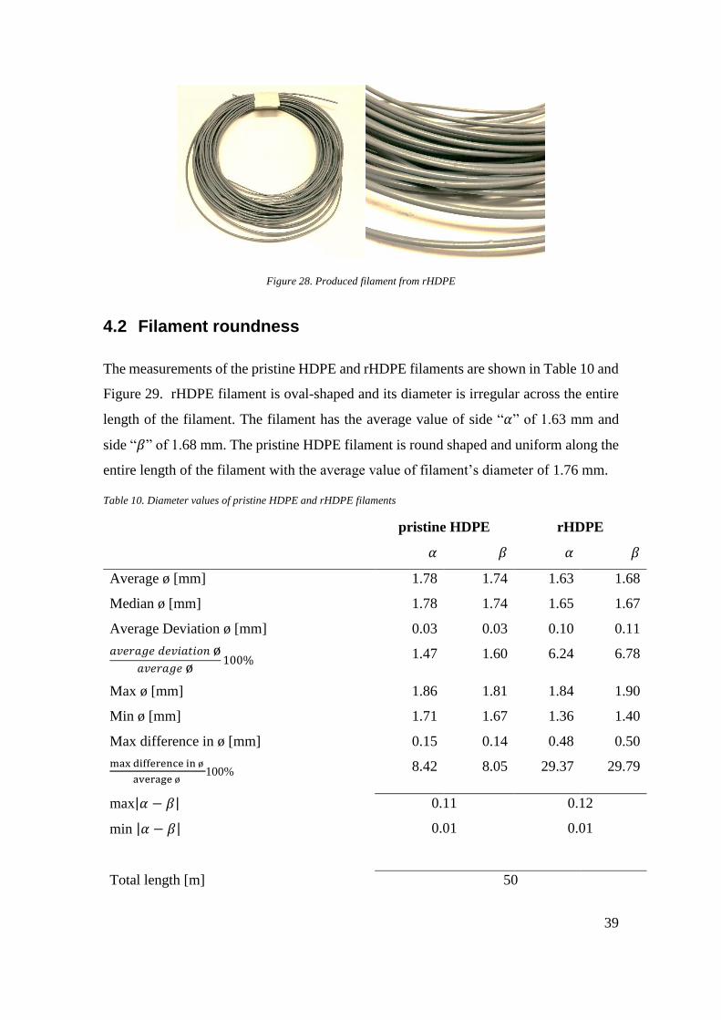
particles while rHDPE was often peppered with foreign debris, see Figure 28.
39
Figure 28. Produced filament from rHDPE
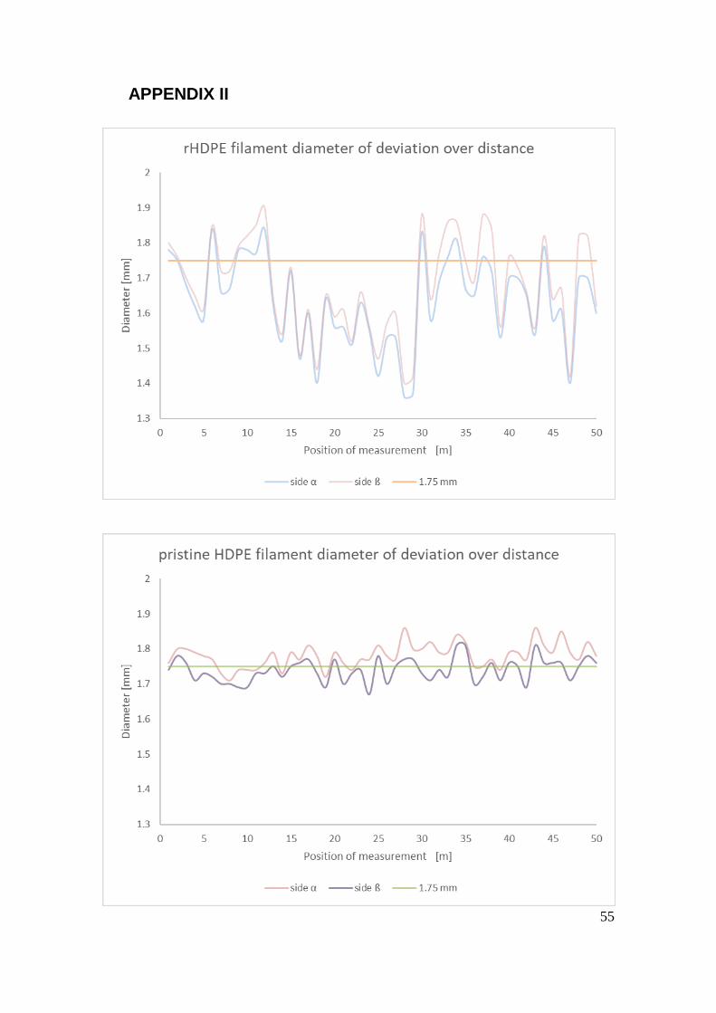
4.2 Filament roundness
The measurements of the pristine HDPE and rHDPE filaments are shown in Table 10 and
Figure 29. rHDPE filament is oval-shaped and its diameter is irregular across the entire
length of the filament. The filament has the average value of side “𝛼” of 1.63 mm and
side “𝛽” of 1.68 mm. The pristine HDPE filament is round shaped and uniform along the
entire length of the filament with the average value of filament’s diameter of 1.76 mm.
Table 10. Diameter values of pristine HDPE and rHDPE filaments
pristine HDPE rHDPE
𝛼 𝛽 𝛼 𝛽
Average ø [mm] 1.78 1.74 1.63 1.68
Median ø [mm] 1.78 1.74 1.65 1.67
Average Deviation ø [mm] 0.03 0.03 0.10 0.11
𝑎𝑣𝑒𝑟𝑎𝑔𝑒 𝑑𝑒𝑣𝑖𝑎𝑡𝑖𝑜𝑛 ø𝑎𝑣𝑒𝑟𝑎𝑔𝑒 ø
100% 1.47 1.60 6.24 6.78
Max ø [mm] 1.86 1.81 1.84 1.90
Min ø [mm] 1.71 1.67 1.36 1.40
Max difference in ø [mm] 0.15 0.14 0.48 0.50
max difference in ø
average ø 100% 8.42 8.05 29.37 29.79
max|𝛼 − 𝛽| 0.11
0.01
0.12
0.01 min |𝛼 − 𝛽|
Total length [m] 50

40
Figure 29. rHDPE and pristine HDPE averaged filament diameter over distance
4.3 Porosity and impurities
The rHDPE filament had a smooth surface with some impurities and bumps across the
whole length of the filament. Foreign material contamination of rHDPE filament was
overserved with a closer examination of the filament surface under a microscope, see
Figure 30. Black specks and spots were found on the rHDPE filament surface. Pristine
HDPE filament did not have any impurities and imperfection, see Figure 31.
Figure 30. Impurities of rHDPE filament

41
Figure 31. The surface of rHDPE and pristine HDPE filament
Several cross sections of the both filaments were taken and examined under an optical
microscope to determine the void content percentage in the filaments. Some features were
detected on the cross-sectional area of the rHDPE, see Figure 32, but they cannot be iden-
tified as empty spaces due to insufficient sample preparation. Therefore, the void fraction
measurement was not performed.
Figure 32. The cross section of rHDPE and pristine HDPE filament
Thermal properties
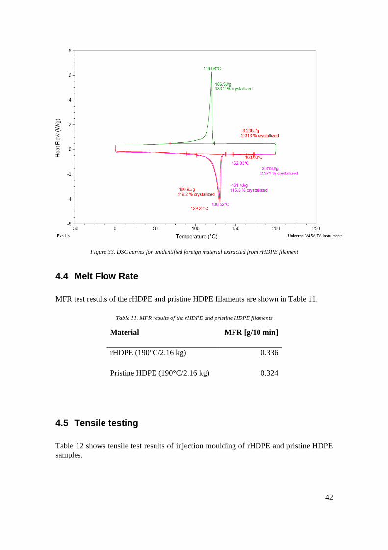
The melting peak of the sample is 129.22 °C during the first heating and 130.52 °C during
the second heating as shown in Figure 33 below. The unidentified foreign material ex-
tracted from rHDPE filament has a high degree of crystallinity of 119.2% and 115,3%.
Heat capacity of the material does not fluctuate to a large extent throughout the testing.
The results differ from the normal HDPE values, though.
rHDPE HDPE
rHDPE HDPE
42
Figure 33. DSC curves for unidentified foreign material extracted from rHDPE filament
4.4 Melt Flow Rate
MFR test results of the rHDPE and pristine HDPE filaments are shown in Table 11.
Table 11. MFR results of the rHDPE and pristine HDPE filaments
Material MFR [g/10 min]
rHDPE (190°C/2.16 kg) 0.336
Pristine HDPE (190°C/2.16 kg) 0.324
4.5 Tensile testing
Table 12 shows tensile test results of injection moulding of rHDPE and pristine HDPE
samples.
43
Table 12. Tensile test results of injection moulding of rHDPE and pristine HDPE samples
rHDPE pristine HDPE
Stress at Yield [MPa] 12.92 9.97
Stress at Break [MPa] 10 3.48
Strain at Yield [%] 2.62 0.96
Strain at Break [%] 15.24 16.3
Youngs Modulus [MPa] 755 915.6
Table 13 shows tensile test results of 3D printed rHDPE and pristine HDPE samples
Table 13. Tensile test results of printed rHDPE and pristine HDPE samples
printed rHDPE printed pristine HDPE
Stress at Yield [MPa] 10.36 7.4
Stress at Break [MPa] - 9
Strain at Yield [%] 5.50 3
Strain at Break [%] - 84.6
Youngs Modulus [MPa] 336 385
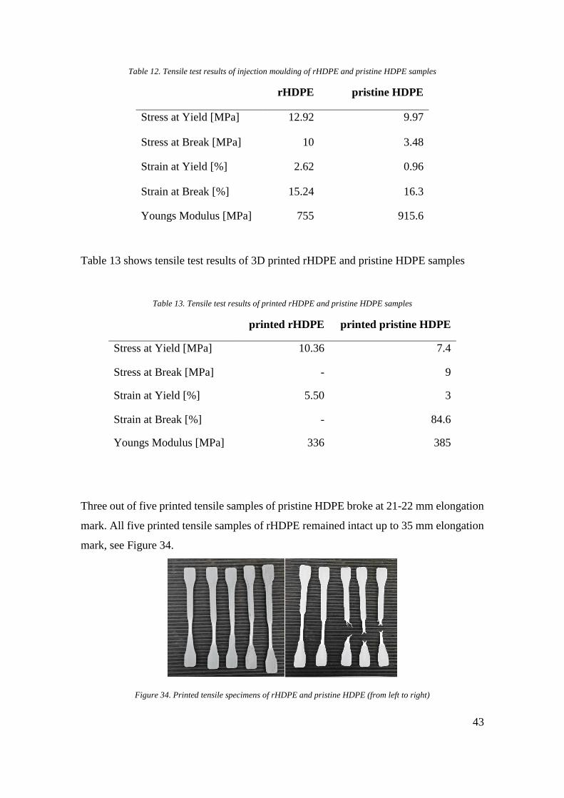
Three out of five printed tensile samples of pristine HDPE broke at 21-22 mm elongation
mark. All five printed tensile samples of rHDPE remained intact up to 35 mm elongation
mark, see Figure 34.
Figure 34. Printed tensile specimens of rHDPE and pristine HDPE (from left to right)

44
4.6 3D printing
The first layers of the rHDPE and HDPE tensile samples managed to stick to the to the
PP sheet. But the adhesion problem of the first layers was not completely fixed even with
increased temperature of printer’s build platform, see Figure 35.
Figure 35. Warping of the rHDPE tensile sample
Printed samples of the cube shrank as they were cooled down to room temperature. The
first layers of the cube models curled at the corners as shown in Figure 36.
Figure 36. Warping of rHDPE and HDPE cube models
The warping of the thin walls of the hollow cube samples became apparent even during
printing process. The hollow cylindrical samples did not show noticeable warp defor-
mation due to its geometrical specification, lack of sharp features, see Figure 37.
Figure 37. Warping results of the hollow cubes and cylinders samples
rHDPE rHDPE HDPE HDPE
rHDPE rHDPE HDPE HDPE

45
The rHDPE layers of the filament effectively bonded to each other as well as pristine
HDPE filaments, see Figure 38. All printed samples did show any sign of layers splitting
or separations.
Figure 38. rHDPE printed samples of hollow cube and cylinder
5 DISCUSSION
Extrusion
The material flow stoppage was the main problem of rHDPE extrusion process. The cause
of this problem was not found. The change of extrusion temperatures and screw speed
during several trial runs did not have any effect on material flow performance. The ma-
terial flow stoppage could be caused by blockage of die, melting instability or unsuitabil-
ity of the extrusion screw since rHDPE consists of various blends of HDPE polymers
with different molecular weight, molecular weight distribution and chain branching [4].
Filament roundness
rHDPE filament with a diameter of 1.75 mm and a tolerance of ± 0.05 mm was difficult
to manufacture. The non-uniformity and inconsistency of diameter of the rHDPE fila-
ment might have been caused by the same unknown factors that caused the stoppage. The
max diameter value of rHDPE filament was 1.90 mm and the min diameter value of
rHDPE filament was 1.36 mm. On the other hand, the average diameter value of pristine
HDPE filament was 1.76 mm.
Impurities
Black dots and bumps on the rHDPE filament surface could be pieces of different grades
of HDPE material which did not entirely melt during reprocessing. rHDPE was recycled
from MSW and the material could be contaminated with other plastics. In that case, the

46
properties of rHDPE filament may not be consistent since small amounts of a different
types of plastics may change the properties of the bulk material (HDPE).
MFR
The MFR test showed that there is no difference between raw materials values and pro-
cessed materials values of rHDPE. The raw rHDPE has MFR of 0,35 g/10min and
rHDPE filament MFR is 0.336 g/10min indicating a decrease of 4% in MFR value of
provided raw rHDPE. Pristine bulk HDPE has MFR of 0.4g/10min and extruded HDPE
filament MFR is 0.324 g/10 min indicating a decrease of 19% in MFR value of pro-
vided raw HDPE. rHDPE has significantly higher material viscosity than most common
commercial filaments such as ABS and PLA.
Tensile test
The maximum value of stress at yield of pristine HDPE printed sample is 15.6 MPa and
the maximum value of stress at yield of rHDPE printed sample is 16.4 MPa. The mean
elongation at breaking point for 3D printed samples of pristine HDPE is 27.9 mm with
minimum value of 21.6 mm. 3D printed samples of rHDPE did not fracture at 35 mm
elongation mark which will be 106% from the total length of the sample. The ductility of
3D printed samples can be explained by molecular orientation of the extruded filament
and alignment of the printed layers of the tested parts. Nevertheless, the unidirectional
strength of the rHDPE printed samples is higher than in pristine HDPE printed samples.
Injection moulded samples of rHDPE and pristine HDPE did not show any signs of
stretchiness. The mean elongation at breaking point for rHDPE injection moulded sam-
ples is 10,49 mm and the mean elongation at break for pristine printed HDPE samples is
11.23 mm. Overall, rHDPE material did not show significant difference in obtained val-
ues compare to pristine HDPE. In some cases, rHDPE performed even better than pristine
material.
3D printing
rHDPE and pristine HDPE filaments did not clog the print nozzle nor jam the drive gears
of the extruder during printing process. The print times did not exceed 20 min, though.
The rHDPE filament diameter irregularity would have caused more problems for an ex-
truder process with a longer running time. The rHDPE and pristine HDPE printed parts

47
show significant warping and first layer adhesion issues, but it was expected. Aside from
these issues rHDPE filament does not display any irregularity in printing behaviour.
6 CONCLUSION
This work evaluates the suitability of CIRCO® rHDPE as a feedstock material for FDM
printing. The empirical research of this thesis covered the entire manufacturing chain:
from filament production to 3D printing. Suitable extrusion parameters for manufacturing
rHDPE filament were not found since the uniformity and roundness of the filament along
the whole length were not reached.
rHDPE did not show major differences compare to reference HDPE during tensile testing
of printed specimens. rHDPE filament values of stress at yield, stress at break and strain
at yield were even higher than values of the pristine material. In addition, rHDPE printed
samples did not fracture during tensile testing.
The literature research indicates that HDPE undesirability stems from its highly crystal-
line polymer structure. Large HDPE prints require specific considerations to counter poor
first layer adhesion and warpage from differential cooling. rHDPE did not display major
disadvantages compared to pristine HDPE during printing. rHDPE filament did not clog
the print nozzle nor jam the drive gears of the extruder during printing even though di-
ameter of the rHDPE filament was not consistent and was oval-round shaped along the
whole length. In conclusion, rHDPE filament from MSW is quite suitable for 3D printing.
Further research is required to improve the extrusion process. In addition, a heated enclo-
sure system for the 3D printer can be beneficial in controlling the differential shrinkage
and warpage of the printed rHDPE parts.

48
REFERENCES
[1] Andrady, AL 2015, Plastics and Environmental Sustainability, Wiley, Somerset.
Available from: ProQuest Ebook Central. [5 April 2018].
[2] Aguado, J, & Serrano, DP 2007, Feedstock Recycling of Plastic Wastes, Royal Soci-
ety of Chemistry, Cambridge. Available from: ProQuest Ebook Central. [25 April 2018].
[3] Lipson, H, & Kurman, M 2010, Fabricated: The New World of 3D Printing, John
Wiley & Sons, Incorporated, Somerset. Available from: ProQuest Ebook Central. [5 April
2018].
[4] Subramanian, MN 2011, Basics of Troubleshooting in Plastics Processing: An Intro-
ductory Practical Guide, Wiley, Hoboken. Available from: ProQuest Ebook Central. [10
April 2018].
[5] Hausman, KK, & Horne, R 2014, 3D Printing For Dummies, Wiley, Somerset. Avail-
able from: ProQuest Ebook Central. [25 April 2018].
[6] Noorani, R 2017, 3D Printing: Technology, Applications, and Selection, CRC Press,
Milton. Available from: ProQuest Ebook Central. [25 April 2018].
[7] University of Exeter, 2018, What is additive layer manufacturing? [online]. Available
from: http://emps.exeter.ac.uk/engineering/research/calm/whatis/ [5 April 2018].
[8] Stokes, MB 2013, 3D Printing for Architects with MakerBot, Packt Publishing, Olton.
Available from: ProQuest Ebook Central. [25 April 2018].
[9] RepRap, 2018, FDM printer process. [online]. Available from:
http://reprap.org/wiki/File:FFF.png [30 January 2018].
[10] Jean le Bouthillier, 2016, The Importance of High Quality 3D Printer Filament, Boot
Industry. [online]. Available from: http://bootsindustries.com/the-importance-of-high-
quality-3d-printer-filament [14 March 2018].

49
[11] Simply3D, 2018, Print Quality Troubleshooting Guide. [online]. Available from:
https://www.simplify3d.com/support/print-quality-troubleshooting/#print-not-sticking-
to-the-bed [14 March 2018].
[12] Tyler Anderson, 2016, Choosing the Best 3D Printing Bed Surface. [online]. Avail-
able from: https://www.matterhackers.com/news/choosing-the-right-3d-print-bed-sur-
face [6 April 2018].
[13] Kutz, M (ed.) 2011, Applied Plastics Engineering Handbook: Processing and Mate-
rials, William Andrew, Binghamton. Available from: ProQuest Ebook Central. [25 April
2018].
[14] Giles, HFJ, Wagner, JRJ, & Mount, EM 2013, Extrusion: The Definitive Processing
Guide and Handbook, William Andrew, Saint Louis. Available from: ProQuest Ebook
Central. [20 April 2018].
[15] Goodship, V 2004, ARBURG Practical Guide to Injection Moulding, iSmithers
Rapra Publishing, Shrewsbury. Available from: ProQuest Ebook Central. [20 April
2018].
[16] MatterHackers, 2016, How To: Vapor Polishing ABS 3D Printer Filament. [online].
Available from: https://www.matterhackers.com/articles/how-to-vapor-polishing [25
April 2018].
[17] Brydson, JA, & Brydson, JA 1999, Plastics Materials, Elsevier Science & Technol-
ogy, Oxford. Available from: ProQuest Ebook Central. [25 April 2018].
[18] Abdel-Bary, E 2003, Handbook of Plastic Films, iSmithers Rapra Publishing,
Shrewsbury. Available from: ProQuest Ebook Central. [23 April 2018].
[19] Michael Sepe, 2014, Performance in Polyethylene: Density Matters, Plastics Tech-
nology. [online]. Available from: https://www.ptonline.com/columns/materials-perfor-
mance-in-polyethylene-density-matters. [22 April 2018].
[20] P.M., V, & Morlanes, MJM 2015, Polyethylene-Based Blends, Composites and
Nanocomposities, John Wiley & Sons, Incorporated, New York. Available from:
ProQuest Ebook Central. [25 April 2018].

50
[21] Vasile, C, & Pascu, M 2005, Practical Guide to Polyethylene, iSmithers Rapra Pub-
lishing, Shawbury. Available from: ProQuest Ebook Central. [25 April 2018].
[22] Gardner, John M.; Stelter, Christopher J.; Yashin, Edward; Siochi, Emile J. High,
2016, Temperature Thermoplastic Additive Manufacturing Using Low-Cost Open-
Source Hardware, NASA Langley Research Center. [online]. Available from:
https://ntrs.nasa.gov/archive/nasa/casi.ntrs.nasa.gov/20170000214.pdf [30 March 2018].
[23] Brewis, DM, & Mathieson, I 2002, Adhesion and Bonding to Polyolefins, iSmithers
Rapra Publishing, Shrewsbury. Available from: ProQuest Ebook Central. [25 April
2018].
[24] Janne Petteri Hämäläinen, 2017, Semi-crystalline polyolefins in fused deposition
modeling, Tampre University of Technology. [online]. Available from:
http://URN.fi/URN:NBN:fi:tty-201708241800 [30 March 2018].
[25] Troughton, MJ, & International, IOW 2008, Handbook of Plastics Joining: A Prac-
tical Guide, William Andrew, Norwich. Available from: ProQuest Ebook Central. [25
April 2018].
[26] Greg Seaman, 2012, Plastics by the Numbers, Eartheasy. [online]. Available from:
https://learn.eartheasy.com/articles/plastics-by-the-numbers/ [7 March 2018].
[27] Fortum, 2018, Ekokem is now Fortum. [online]. Available from: https://www3.for-
tum.com/media/2017/04/ekokem-now-fortum [7 March 2018].
[28] Fortum, 2018, Recycling and waste management solution. [online]. Available from:
https://stateofgreen.com/files/download/3277 [7 March 2018].
[29] Fortum, 2018, Fortum Circo® High Density Polyethylene Material Datasheet
[online]. Available from: http://ekokem.studio.crasman.fi/pub/Circoplastics/pdf/CIRCO-
HDPE.pdf [7 March 2018].
[30] Encyclopaedia of engineering, 2015, Extrusion of Plastics| Extrusion moulding| Ex-
trusion Process. [online]. Available from: http://www.mechscience.com/extrusion/ [7
March 2018].

51
[31] Lafleur, P, & Vergnes, B (eds) 2014, Polymer Extrusion, John Wiley & Sons, Incor-
porated, Somerset. Available from: ProQuest Ebook Central. [15 April 2018].
[32] Wong, CH, Yeong, WY, & Chua, CK 2017, Standards, Quality Control and Meas-
urement Sciences in 3D Printing and Additive Manufacturing, Elsevier Science & Tech-
nology, San Diego. Available from: ProQuest Ebook Central. [1 April 2018].
[33] Brown, R 2002, Handbook of Polymer Testing: Short-term Mechanical Tests,
iSmithers Rapra Publishing, Shrewsbury. Available from: ProQuest Ebook Central. [25
April 2018].
[34] Davis, JR (ed.) 2004, Tensile Testing, A S M International, Materials Park. Available
from: ProQuest Ebook Central. [5 April 2018].
[35] Kemmish, DJ, Schubert, S, & Schlufter, K 2011, Practical Guide to High Perfor-
mance Engineering Plastics, iSmithers Rapra Publishing, Shrewsbury. Available from:
ProQuest Ebook Central. [5 April 2018].
[36] Toray, 2018, Melt Viscosity Properties. [online]. Available from:
http://www.toray.jp/plastics/en/torelina/technical/tec_017.html [7 March 2018].
[37] Prospector, 2018, Acrylonitrile Butadiene Styrene (ABS) Typical Properties Generic
ABS. [online]. Available from: https://plastics.ulprospector.com/generics/1/c/t/acryloni-
trile-butadiene-styrene-abs-properties-processing [1 March 2018].
[38] Prospector, 2018, Polylactic Acid (PLA) Typical Properties. [online]. Available
from: https://plastics.ulprospector.com/generics/34/c/t/polylactic-acid-pla-properties-
processing [7 March 2018].
[39] Prospector, 2018, Polycarbonate (PC) Typical Properties. [online]. Available from:
https://plastics.ulprospector.com/generics/25/c/t/polycarbonate-pc-properties-processing
[7 March 2018].
[40] Prospector, 2018, Polystyrene (PS) Typical Properties (HIPS). [online]. Available
from: https://plastics.ulprospector.com/generics/43/c/t/polystyrene-ps-properties-pro-
cessing/sp/4 [7 March 2018].

52
[41] Dumbbell Co., LTD, Super Dumbbell Cutters. [online]. Available from:
http://www.dumbbell.co.jp/english/super_dumbbell01.html [8 March 2018].
[42] Frans Johansson, 2016, Optimizing Fused Filament Fabrication 3D printing for du-
rability, Blekinge Institute of Technology, Karlskrona, Sweden. [online]. Available from:
http://www.diva-portal.org/smash/get/diva2:940935/FULLTEXT02 [1 March 2018].
53
APPENDIX I

54
55
APPENDIX II

56
APPENDIX III

57