recursive filter
TRANSCRIPT
Recursive Filters
04/11/23
Introduction
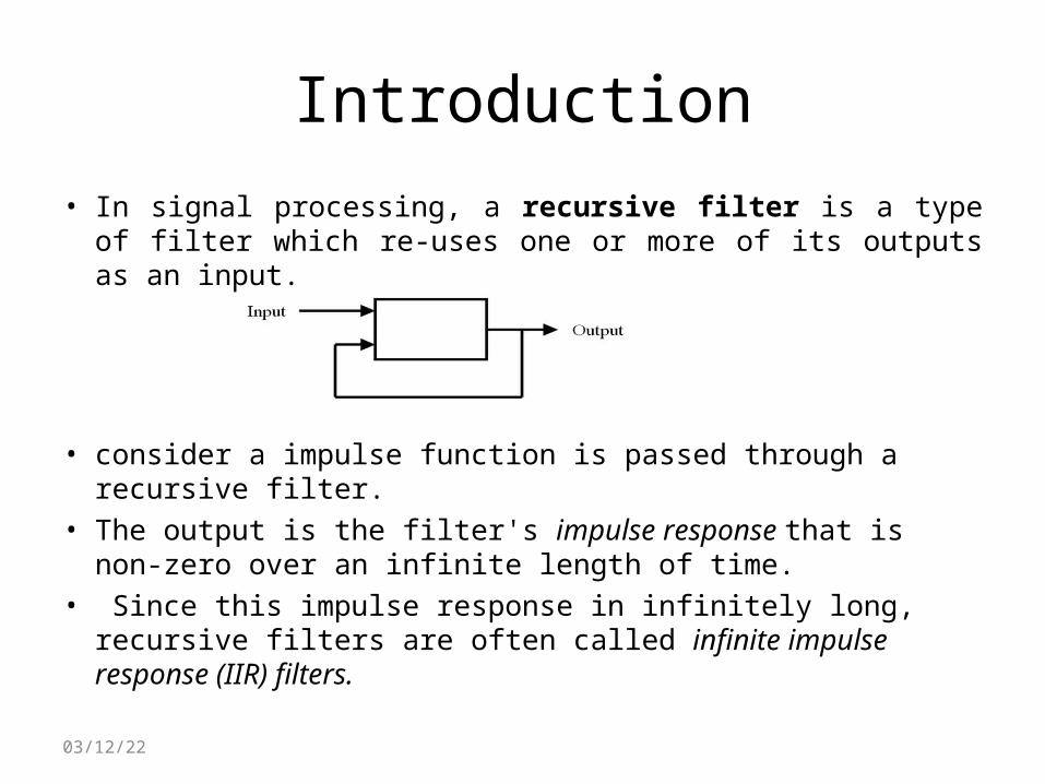
• In signal processing, a recursive filter is a type of filter which re-uses one or more of its outputs as an input.
• consider a impulse function is passed through a recursive filter.
• The output is the filter's impulse response that is non-zero over an infinite length of time.
• Since this impulse response in infinitely long, recursive filters are often called infinite impulse response (IIR) filters.
04/11/23
Types of Recursive Filter
• Single Pole Recursive Filter
• Narrow-band Recursive Filter
• Bidirectional Recursive Filter
• Kalman Recursive Filter
04/11/23
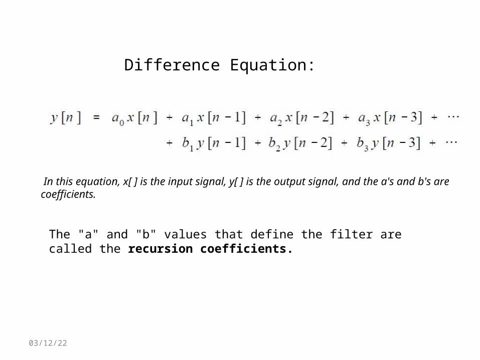
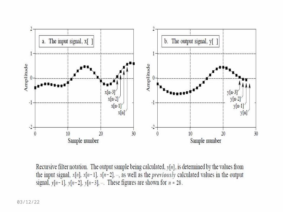
Difference Equation:
In this equation, x[ ] is the input signal, y[ ] is the output signal, and the a's and b's are coefficients.
The "a" and "b" values that define the filter are called the recursion coefficients.
04/11/23
04/11/23
Single Pole Recursive Filters
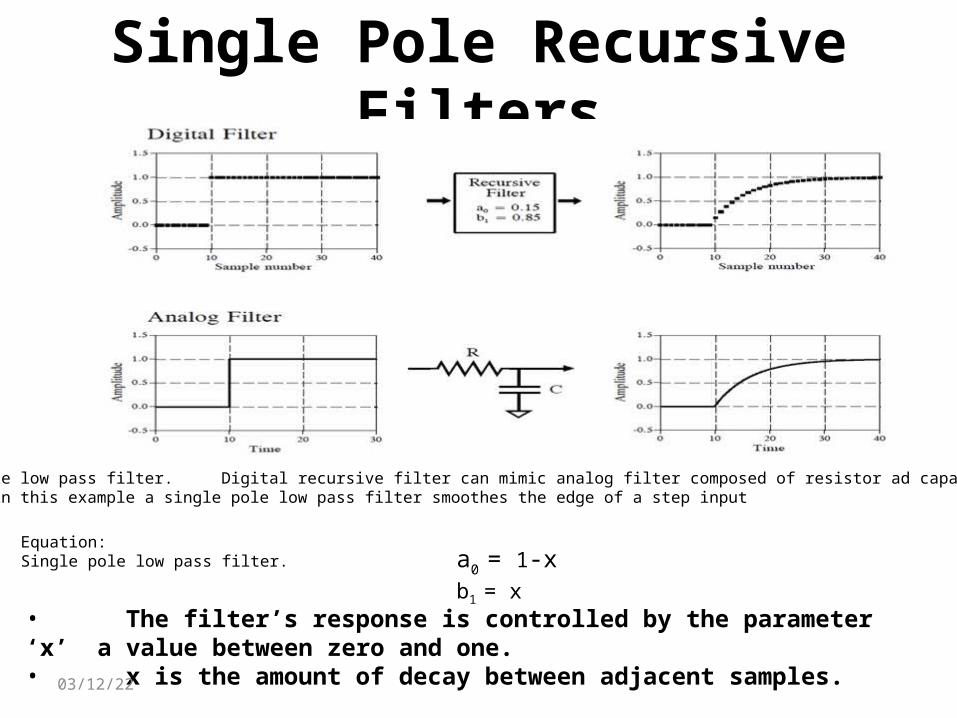
a0 = 1-xb1 = x
Equation:Single pole low pass filter.
Single pole low pass filter. Digital recursive filter can mimic analog filter composed of resistor ad capacitor. As shown in this example a single pole low pass filter smoothes the edge of a step input
• The filter’s response is controlled by the parameter ‘x’ a value between zero and one.• x is the amount of decay between adjacent samples.
04/11/23
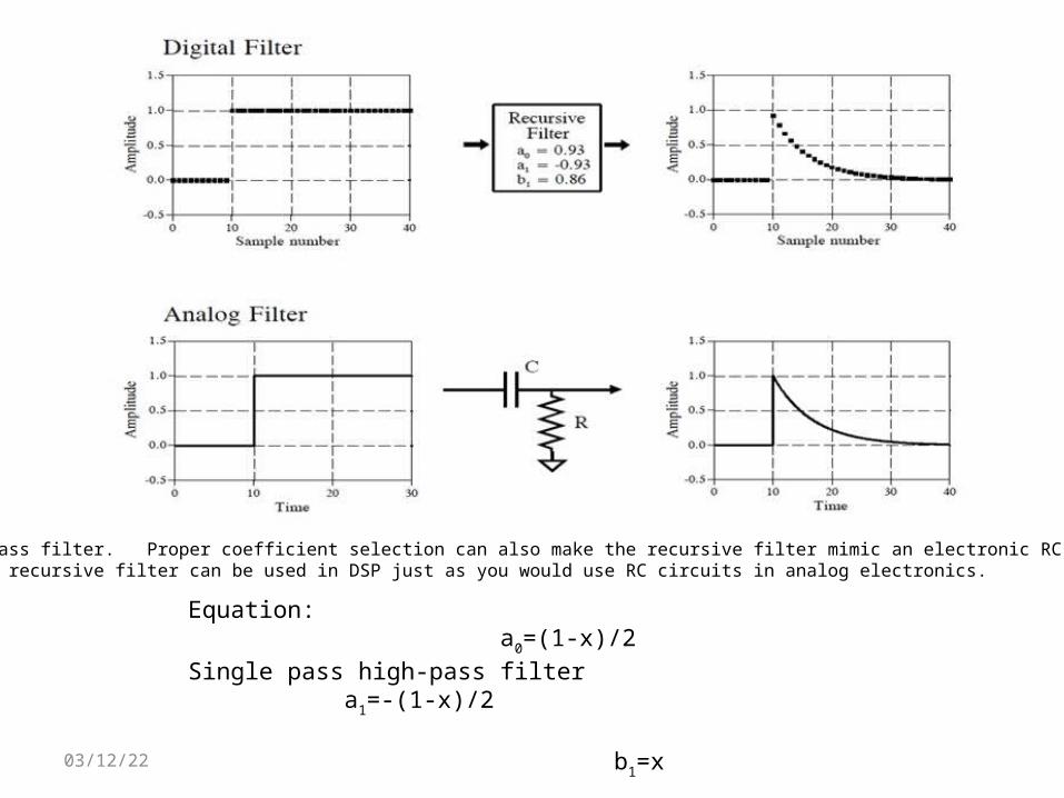
Single pole high-pass filter. Proper coefficient selection can also make the recursive filter mimic an electronic RC high-pass filter. These single pole recursive filter can be used in DSP just as you would use RC circuits in analog electronics.
Equation: a0=(1-x)/2 Single pass high-pass filter a1=-(1-x)/2 b1=x
04/11/23
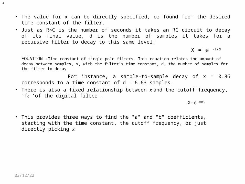
• The value for x can be directly specified, or found from the desired time constant of the filter.
• Just as R×C is the number of seconds it takes an RC circuit to decay of its final value, d is the number of samples it takes for a recursive filter to decay to this same level:
X = e -1/d
EQUATION :Time constant of single pole filters. This equation relates the amount of decay between samples, x, with the filter's time constant, d, the number of samples for the filter to decay
For instance, a sample-to-sample decay of x = 0.86 corresponds to a time constant of d = 6.63 samples.
• There is also a fixed relationship between x and the cutoff frequency, ‘fC ‘of the digital filter .
X=e-2πfc
• This provides three ways to find the "a" and "b" coefficients, starting with the time constant, the cutoff frequency, or just directly picking x.
d
04/11/23
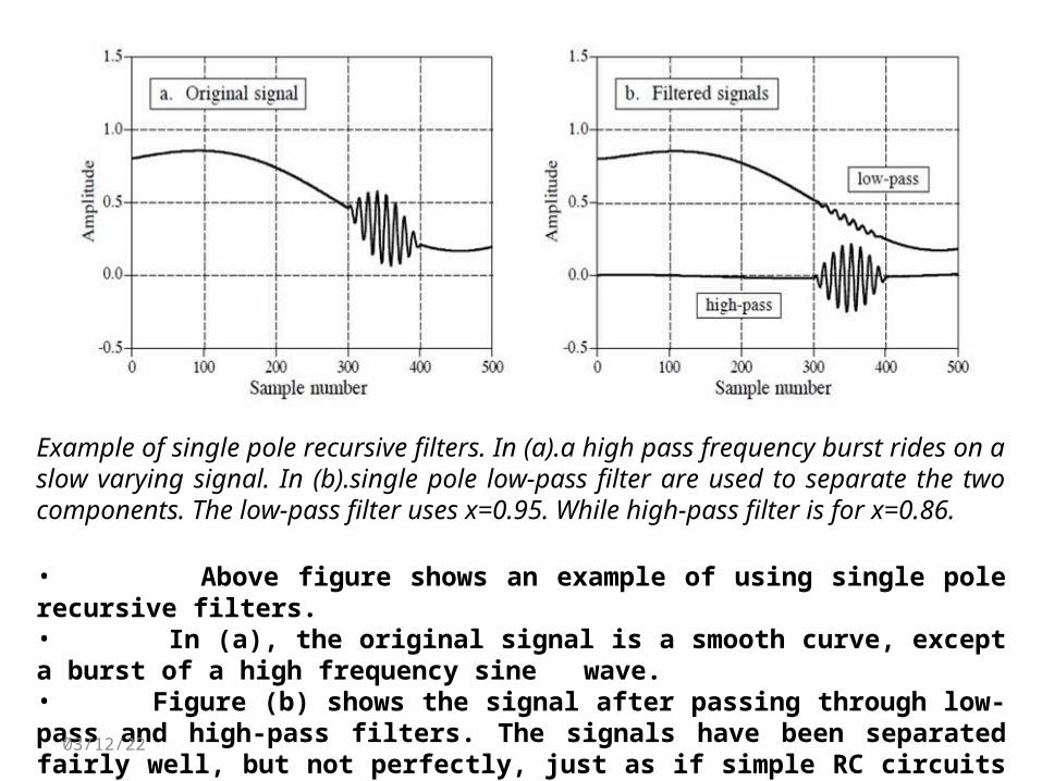
Example of single pole recursive filters. In (a).a high pass frequency burst rides on a slow varying signal. In (b).single pole low-pass filter are used to separate the two components. The low-pass filter uses x=0.95. While high-pass filter is for x=0.86.
• Above figure shows an example of using single pole recursive filters. • In (a), the original signal is a smooth curve, except a burst of a high frequency sine wave. • Figure (b) shows the signal after passing through low-pass and high-pass filters. The signals have been separated fairly well, but not perfectly, just as if simple RC circuits were used on an analog signal.
04/11/23
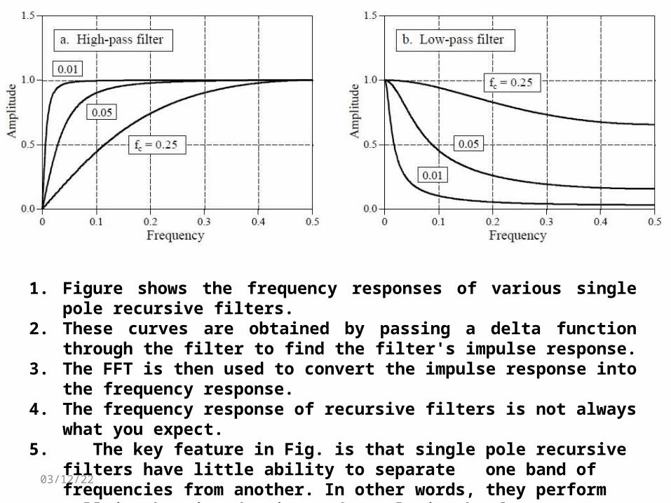
1. Figure shows the frequency responses of various single pole recursive filters. 2. These curves are obtained by passing a delta function through the filter to find the
filter's impulse response. 3. The FFT is then used to convert the impulse response into the frequency response.4. The frequency response of recursive filters is not always what you expect.5. The key feature in Fig. is that single pole recursive filters have little ability to separate
one band of frequencies from another. In other words, they perform well in the time domain, and poorly in the frequency domain.
04/11/23
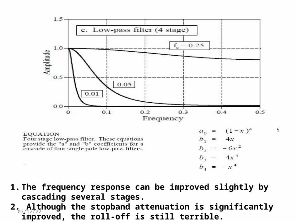
Figure shows the frequency response of a cascade of four low-pass filters.
1. The frequency response can be improved slightly by cascading several stages.2. Although the stopband attenuation is significantly improved, the roll-off is still
terrible.04/11/23
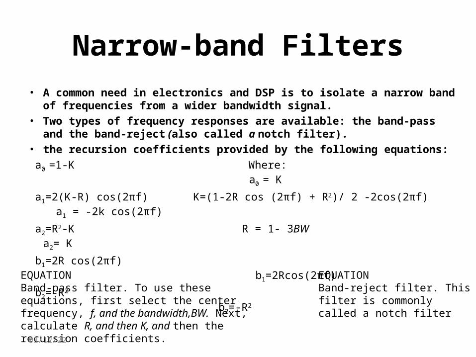
Narrow-band Filters• A common need in electronics and DSP is to isolate a narrow band of
frequencies from a wider bandwidth signal.• Two types of frequency responses are available: the band-pass and the band-
reject (also called a notch filter).• the recursion coefficients provided by the following equations:
a0 =1-K Where: a 0 = K
a1=2(K-R) cos(2πf) K=(1-2R cos (2πf) + R2)/ 2 -2cos(2πf) a1 = -2k cos(2πf)
a2=R2-K R = 1- 3BW a2= K
b1=2R cos(2πf) b 1=2Rcos(2πf)
b2=-R2 b2=-R2EQUATION Band-pass filter. To use these equations, first select the center frequency, f, and the bandwidth,BW. Next, calculate R, and then K, and then the recursion coefficients.
EQUATION Band-reject filter. This filter is commonlycalled a notch filter
04/11/23
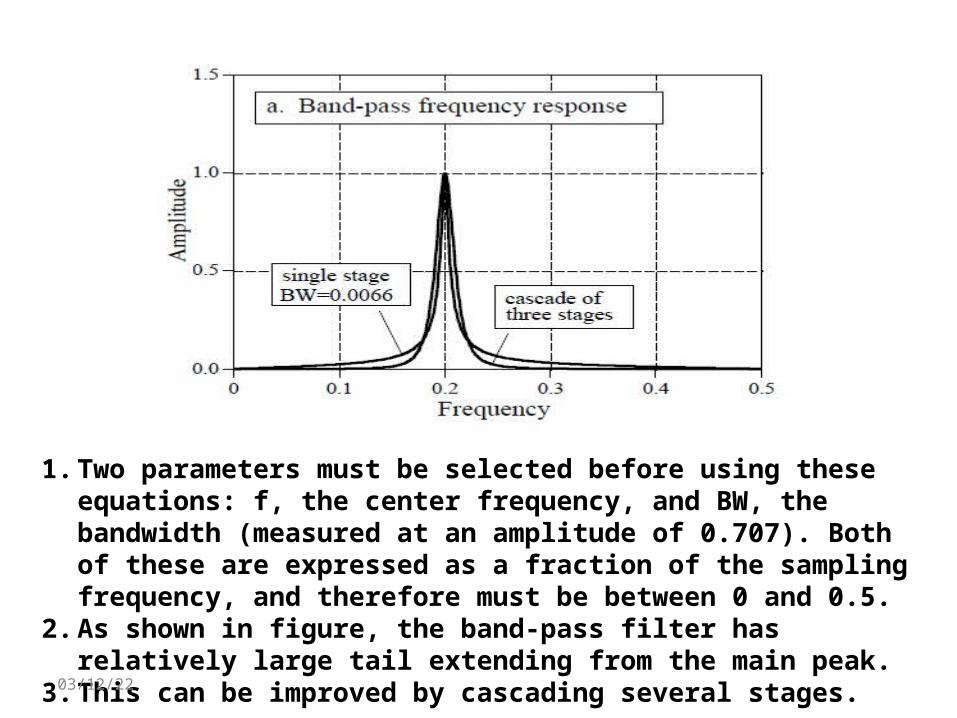
1. Two parameters must be selected before using these equations: f, the center frequency, and BW, the bandwidth (measured at an amplitude of 0.707). Both of these are expressed as a fraction of the sampling frequency, and therefore must be between 0 and 0.5.
2. As shown in figure, the band-pass filter has relatively large tail extending from the main peak.
3. This can be improved by cascading several stages.04/11/23
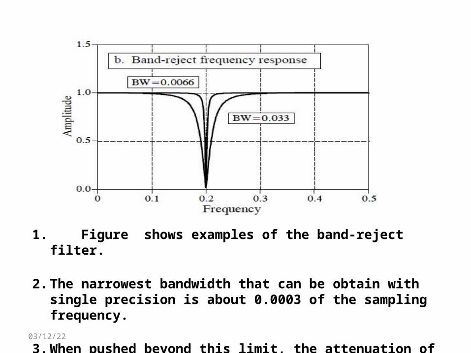
1. Figure shows examples of the band-reject filter.
2. The narrowest bandwidth that can be obtain with single precision is about 0.0003 of the sampling frequency.
3. When pushed beyond this limit, the attenuation of the notch will degrade.
04/11/23
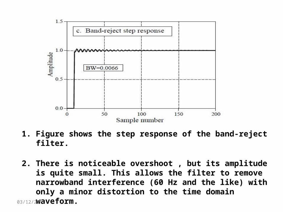
1. Figure shows the step response of the band-reject filter.
2. There is noticeable overshoot , but its amplitude is quite small. This allows the filter to remove narrowband interference (60 Hz and the like) with only a minor distortion to the time domain waveform.
04/11/23
conclusion• The beauty of the recursive method is in its ability to create a wide variety of
responses by changing only a few parameters.
• We can use them to process digital signals just as you would use RC networks to process analog electronic signals. This includes everything we would expect: DC removal, high-frequency noise suppression, wave shaping, smoothing, etc.
04/11/23
Reference• The Scientist and Engineer's Guide to Digital Signal Processing - By Steven
W. Smith, Ph.D.
• Signal and System - By simon Haykin.
• Analog and Digital signal Processing - By Ashok Ambardar.
04/11/23

Thank you
04/11/23