rectification of the chordal axis transform skeleton and criteria for shape decomposition
TRANSCRIPT
www.elsevier.com/locate/imavis
Image and Vision Computing 25 (2007) 1557–1571
Rectification of the chordal axis transform skeleton and criteriafor shape decomposition
Lakshman Prasad *
Space and Remote Sensing Sciences Group (ISR-2), International, Space, and Response Division, Los Alamos National Laboratory, Los Alamos,
NM 87545, USA
Received 3 December 2005; received in revised form 16 April 2006; accepted 22 June 2006
Abstract
Skeletonization and parts-based decomposition are important to the analysis, characterization, and recognition of shapes. In earlierworks we proposed the chordal axis transform (CAT), based on constrained Delaunay triangulations (CDT), for analyzing discreteshapes. In this paper, we refine the CAT skeleton to have smoother branches and stable branch points of any degree based on approx-imate co-circularity of edge-adjacent triangles. We also introduce new criteria for obtaining visually meaningful shape decompositionsusing approximate co-circularity and a discrete axial derivative for shapes based on their CDTs.� 2006 Elsevier B.V. All rights reserved.
Keywords: Shape; Delaunay triangulation; Chordal axis; Medial axis; Skeleton; Shape decomposition; Co-circularity; Shape graph; Grouping
1. Introduction
1.1. Shape skeletonization
The skeleton of a two-dimensional shape is an impor-tant descriptor that provides structural information aboutthe shape. Skeletons are used to compare shapes, identifyshape parts, and, in case of thin objects such as textualcharacters, even represent the shapes themselves. Blum [1]defined the skeleton of a two-dimensional shape with acontinuous closed contour as the locus of centers of maxi-mal discs (i.e., discs touching the shape contour at two ormore points) interior to the shape, with each center attrib-uted the radius of the corresponding maximal disc. Thisdefinition of the skeleton of a shape is known as the medialaxis transform (MAT) of the shape. While the MAT is anelegant characterization of the skeleton of a shape with acontinuous boundary, it has proved to be unstable and dif-ficult to use as a practical tool to analyze shapes [2–4].Indeed, for example, minor oscillations in shape contours
0262-8856/$ - see front matter � 2006 Elsevier B.V. All rights reserved.
doi:10.1016/j.imavis.2006.06.025
* Tel.: +1 505 667 4587; fax: +1 505 664 0362.E-mail address: [email protected]
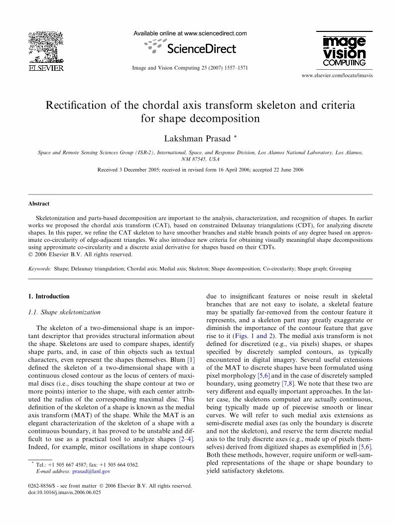
due to insignificant features or noise result in skeletalbranches that are not easy to isolate, a skeletal featuremay be spatially far-removed from the contour feature itrepresents, and a skeleton part may greatly exaggerate ordiminish the importance of the contour feature that gaverise to it (Figs. 1 and 2). The medial axis transform is notdefined for discretized (e.g., via pixels) shapes, or shapesspecified by discretely sampled contours, as typicallyencountered in digital imagery. Several useful extensionsof the MAT to discrete shapes have been formulated usingpixel morphology [5,6] and in the case of discretely sampledboundary, using geometry [7,8]. We note that these two arevery different and equally important approaches. In the lat-ter case, the skeletons computed are actually continuous,being typically made up of piecewise smooth or linearcurves. We will refer to such medial axis extensions assemi-discrete medial axes (as only the boundary is discreteand not the skeleton), and reserve the term discrete medialaxis to the truly discrete axes (e.g., made up of pixels them-selves) derived from digitized shapes as exemplified in [5,6].Both these methods, however, require uniform or well-sam-pled representations of the shape or shape boundary toyield satisfactory skeletons.
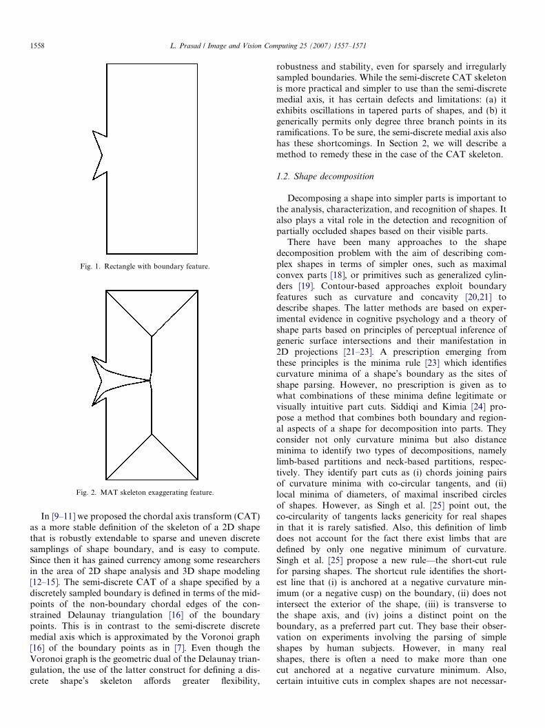
Fig. 1. Rectangle with boundary feature.
Fig. 2. MAT skeleton exaggerating feature.
1558 L. Prasad / Image and Vision Computing 25 (2007) 1557–1571
In [9–11] we proposed the chordal axis transform (CAT)as a more stable definition of the skeleton of a 2D shapethat is robustly extendable to sparse and uneven discretesamplings of shape boundary, and is easy to compute.Since then it has gained currency among some researchersin the area of 2D shape analysis and 3D shape modeling[12–15]. The semi-discrete CAT of a shape specified by adiscretely sampled boundary is defined in terms of the mid-points of the non-boundary chordal edges of the con-strained Delaunay triangulation [16] of the boundarypoints. This is in contrast to the semi-discrete discretemedial axis which is approximated by the Voronoi graph[16] of the boundary points as in [7]. Even though theVoronoi graph is the geometric dual of the Delaunay trian-gulation, the use of the latter construct for defining a dis-crete shape’s skeleton affords greater flexibility,
robustness and stability, even for sparsely and irregularlysampled boundaries. While the semi-discrete CAT skeletonis more practical and simpler to use than the semi-discretemedial axis, it has certain defects and limitations: (a) itexhibits oscillations in tapered parts of shapes, and (b) itgenerically permits only degree three branch points in itsramifications. To be sure, the semi-discrete medial axis alsohas these shortcomings. In Section 2, we will describe amethod to remedy these in the case of the CAT skeleton.
1.2. Shape decomposition
Decomposing a shape into simpler parts is important tothe analysis, characterization, and recognition of shapes. Italso plays a vital role in the detection and recognition ofpartially occluded shapes based on their visible parts.
There have been many approaches to the shapedecomposition problem with the aim of describing com-plex shapes in terms of simpler ones, such as maximalconvex parts [18], or primitives such as generalized cylin-ders [19]. Contour-based approaches exploit boundaryfeatures such as curvature and concavity [20,21] todescribe shapes. The latter methods are based on exper-imental evidence in cognitive psychology and a theory ofshape parts based on principles of perceptual inference ofgeneric surface intersections and their manifestation in2D projections [21–23]. A prescription emerging fromthese principles is the minima rule [23] which identifiescurvature minima of a shape’s boundary as the sites ofshape parsing. However, no prescription is given as towhat combinations of these minima define legitimate orvisually intuitive part cuts. Siddiqi and Kimia [24] pro-pose a method that combines both boundary and region-al aspects of a shape for decomposition into parts. Theyconsider not only curvature minima but also distanceminima to identify two types of decompositions, namelylimb-based partitions and neck-based partitions, respec-tively. They identify part cuts as (i) chords joining pairsof curvature minima with co-circular tangents, and (ii)local minima of diameters, of maximal inscribed circlesof shapes. However, as Singh et al. [25] point out, theco-circularity of tangents lacks genericity for real shapesin that it is rarely satisfied. Also, this definition of limbdoes not account for the fact there exist limbs that aredefined by only one negative minimum of curvature.Singh et al. [25] propose a new rule—the short-cut rulefor parsing shapes. The shortcut rule identifies the short-est line that (i) is anchored at a negative curvature min-imum (or a negative cusp) on the boundary, (ii) does notintersect the exterior of the shape, (iii) is transverse tothe shape axis, and (iv) joins a distinct point on theboundary, as a preferred part cut. They base their obser-vation on experiments involving the parsing of simpleshapes by human subjects. However, in many realshapes, there is often a need to make more than onecut anchored at a negative curvature minimum. Also,certain intuitive cuts in complex shapes are not necessar-

Fig. 4. CAT proto-skeleton of shape in Fig. 1.
L. Prasad / Image and Vision Computing 25 (2007) 1557–1571 1559
ily the shortest cuts. Thus, while the short-cut principlecovers a large class of part cuts, it is not exhaustive.
In Section 3, we present two simple and easily comput-able criteria that apply to discretely sampled shapes, to cre-ate part cuts that are transverse to shape axes, preferboundary negative curvature minima, and are visually intu-itive. Our criteria are based on the notion of approximateco-circularity of Delaunay triangles (used also for rectify-ing the chordal axis skeleton), and on the definition of adiscrete axial derivative of a shape that measures the rateof change of shape width along the axis of the shape.
2. Rectification of the chordal axis skeleton
2.1. Background
In this section, we will review the CAT, its strengths,and drawbacks to set the context for this paper.
Definition 1. A maximal chord of tangency (Fig. 3) connectstwo points of tangency of a maximal disc inscribed in ashape such that at least one of the two arcs of the maximaldisc’s bounding circle subtended by the chord is free ofpoints of tangency with the shape’s boundary.
Definition 2. The Chordal Axis Transform (CAT) of a pla-nar shape is the set of all ordered pairs (p,d), where p and dare either the midpoint and half the length, respectively, ofa maximal chord of tangency, or the center and radius,respectively, of a maximal disc with three or more maximalchords of tangency.
Although the definition of the CAT appears to be a var-iation of that of the MAT, there are important differencesbetween the two transforms. First, the CAT, as defined,yields a piecewise smooth disconnected protoskeleton(Fig. 4). By joining the midpoints of the maximal chords
Fig. 3. A maximal disc and the associated maximal chord of tangency of ashape with continuous boundary.
of each maximal disc with three or more chords to the cen-ter of the maximal disc if the center lies within the polygondetermined by the chords, or to the center of the longestchord otherwise, we obtain a connected skeleton of theshape (Fig. 5).
Second, the CAT can be stably defined for a shapewhose boundary is discrete (i.e., specified as sequences ofpoints separated in space) (Fig. 8). To identify the equiva-lent of maximal chords in the discrete case, we considerempty circles that pass through three or more points ofthe discrete boundary of the shape such that no circle con-tains a boundary point in its interior that is visible to twoboundary points lying on the circle (two vertices u and v ofa simple polygon are visible to each other, if the line seg-ment joining u and v does not intersect the exterior of thepolygon). For a shape with discretely sampled boundary,
Fig. 5. Connected CAT skeleton.

1560 L. Prasad / Image and Vision Computing 25 (2007) 1557–1571
these empty circles play the role of maximal discs (in thecase of shapes specified by continuous boundaries) foridentifying chords. Each such empty circle identifies a tri-angle. The edges of the triangle that do not connect neigh-boring points of the discretely specified shape boundary arethe equivalents of maximal chords of tangency (Fig. 6). Wewill call such edges chords to distinguish them from the tri-angle edges that connect neighboring boundary points.
Fig. 6. An empty circle and the associated Delaunay triangle of a shapewith discrete boundary.
Fig. 7. Construction of skeletal segments in the various types of triangles in than obtuse junction triangle, an acute junction triangle, and a terminal triangle
Fig. 8. Construction of the CAT skeleton of a sparsely and unevenly sampled s(b) CDT and construction of sleeve skeletal segments, (c) connected skeletonMAT skeleton obtained by connecting adjacent Voronoi vertices (circumcenterthe CAT skeleton over that of the MAT of a shape with sparsely sampled co
The triangles so formed are indeed the Delaunay trian-gles of a constrained Delaunay triangulation (CDT) [16]of the interior of the shape as they satisfy the empty circlecriterion. It is worth noting here that this extension of theCAT to discrete shapes is natural from the point of view ofconstructing skeletons. This is because the constrained Del-aunay triangulation is the geometric dual of the generalizedVoronoi axis [16] of the contour point set. Indeed, the semi-discrete MAT is essentially the Voronoi skeleton of theboundary points but restricted to only those branches thatdo not lie between adjacent boundary points. For sparselyor unevenly sampled shapes, there is no guarantee that theVoronoi vertices defining the MAT (and hence, the skele-ton) will always stay inside the shape (Fig. 8d). In usingthe dual of the Voronoi axis, we can define a more robustand manipulable skeleton than the MAT that applies todiscrete shapes whose boundaries are sparsely or unevenlysampled. The CDT of a shape consists of three kinds of tri-angles, namely Junction triangles (J) that have all their edg-es inside the shape and signify shape bifurcations, Sleeve
triangles (S) that have one edge in common with the shapeboundary and signify shape prolongations, and Terminaltriangles (T) that have two edges in common with the shapeboundary and signify shape terminations. The connectedCAT skeleton for a discretized shape is obtained from itsCDT by (i) joining the midpoints of the internal edges ofeach S-triangle by a line segment, (ii) joining the midpointsof the internal edges of each J-triangle to its circumcenter ifthe triangle is acute, or to the midpoint of its longest side ifit is obtuse (Fig. 7). These localized constructions ensurethat the CAT skeleton does not cross the boundary ofthe shape irrespective of the sparsity of sampling (Fig. 8).
e CDT of a shape: from left to right, skeleton segments in a sleeve triangle,(within which no construction is made).
hape and comparison with its discrete MAT skeleton: (a) a discrete shape,after construction of skeletal segment in the junction triangle, (d) discretes of triangles) of the contour points. The comparison shows the stability ofntour.

Fig. 11. Corner detail of Fig. 9. showing CDT and skeleton oscillations.
L. Prasad / Image and Vision Computing 25 (2007) 1557–1571 1561
Henceforth, we will restrict ourselves to the structure of theCAT skeleton in the rest of the paper and direct the inter-ested reader to [11] and [17] for other details and implica-tions of the CAT.
2.2. Drawbacks of the discrete CAT skeleton
The CAT skeleton, as defined above, has certain struc-tural deficiencies (which are also present in discrete realiza-tions of the MAT skeleton) that warrant rectification. TheCAT skeleton exhibits oscillations through shape regionsthat are tapered (Figs. 9–11). The CAT skeleton allowsonly branches of degree three to represent shape ramifica-tions even when higher degree branches are more naturalto represent them (Fig. 10). These deficiencies are artifactsof giving equally important roles to all chords (i.e., internaltriangle edges of the shape’s CDT) in constructing the CATskeleton. Indeed, in [11], we considered degenerate situa-tions where more than three points on a shape boundaryare co-circular with respect to an empty circle. We notedthat the triangle edges that form the chords of the polygondetermined by the co-circular points are not uniquelydefined (i.e., any triangulation of the interior of the co-cir-cular polygon will be consistent with the Delaunay criteri-on of triangulation.) We proposed that the restriction ofthe shape’s skeleton to such a polygon be constructed by
Fig. 9. CAT skeleton showing oscillations in tapered regions of adiscretely sampled rectangular shape.
Fig. 10. CAT skeleton showing degree three branching for a star-likeshape.
joining all the midpoints of the polygon’s edges that areinternal to the shape to the circumcenter of the polygonor, if the latter falls outside the polygon, to the midpointof longest edge of the polygon that does not lie on theshape boundary. In effect, we discarded internal shapechords that are common to two co-circular triangles inthe CDT of a shape. Such co-circularity of four or morepoints are not a generic property of shapes (i.e., they areinfrequent coincidences). However, configurations thatare slight perturbations of this rare occurrence are not sorare. This hints at a solution to the problem of instabilityof skeleton topology in nearby branchpoints of semidis-crete MAT and CAT skeletons. Accordingly, we will gener-alize this notion of co-circularity to define a valuation onthe chords of a shape that will help filter chords whichare common edges of nearly co-circular triangles. Themotivation for this is to prevent common edges of nearlyco-circular triangles from participating in the constructionof the skeleton. Firstly, this will mitigate skeleton oscilla-tions in tapered regions of shapes. Indeed, consider twoadjacent, nearly co-circular, sleeve triangles. Unless theexternal edges of the triangles are parallel (or co-linear),the midpoints of the internal edges of the two triangles willnot lie on a straight line, thus producing an oscillation inthe skeleton. If the common internal edge of this trianglepair is discounted, then the skeleton of the polygon deter-mined by the triangle pair is given by the line segment join-ing the midpoints of the remaining two internal edges, thuslocally rectifying the CAT skeleton of the shape (Fig. 12).Secondly, by grouping nearly co-circular triangles thatare sites of branchings (i.e., J-triangles), multiple branch-points in nearly co-circular regions can be condensed to asingle branchpoint. We firm up and computationallyground this intuitive idea below.
2.3. A measure of chord strength
We introduce a valuation on the chords of a discreteshape’s CAT. The chords of the CAT are edges of theCDT of the shape that are shared by two triangles. Letthe angles opposite a chord c in its two flanking trianglesbe h and /. We then define the strength of c by
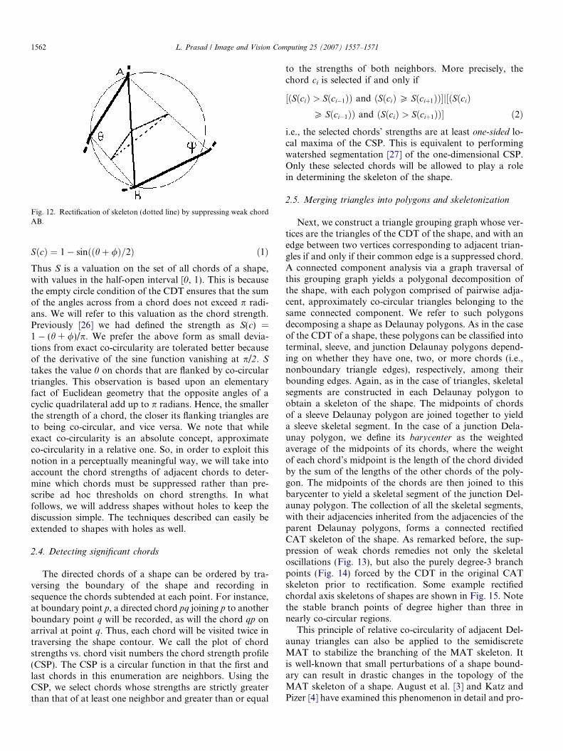
Fig. 12. Rectification of skeleton (dotted line) by suppressing weak chordAB.
1562 L. Prasad / Image and Vision Computing 25 (2007) 1557–1571
SðcÞ ¼ 1� sinððhþ /Þ=2Þ ð1ÞThus S is a valuation on the set of all chords of a shape,with values in the half-open interval [0, 1). This is becausethe empty circle condition of the CDT ensures that the sumof the angles across from a chord does not exceed p radi-ans. We will refer to this valuation as the chord strength.Previously [26] we had defined the strength as S(c) =1 � (h + /)/p. We prefer the above form as small devia-tions from exact co-circularity are tolerated better becauseof the derivative of the sine function vanishing at p/2. S
takes the value 0 on chords that are flanked by co-circulartriangles. This observation is based upon an elementaryfact of Euclidean geometry that the opposite angles of acyclic quadrilateral add up to p radians. Hence, the smallerthe strength of a chord, the closer its flanking triangles areto being co-circular, and vice versa. We note that whileexact co-circularity is an absolute concept, approximateco-circularity in a relative one. So, in order to exploit thisnotion in a perceptually meaningful way, we will take intoaccount the chord strengths of adjacent chords to deter-mine which chords must be suppressed rather than pre-scribe ad hoc thresholds on chord strengths. In whatfollows, we will address shapes without holes to keep thediscussion simple. The techniques described can easily beextended to shapes with holes as well.
2.4. Detecting significant chords
The directed chords of a shape can be ordered by tra-versing the boundary of the shape and recording insequence the chords subtended at each point. For instance,at boundary point p, a directed chord pq joining p to anotherboundary point q will be recorded, as will the chord qp onarrival at point q. Thus, each chord will be visited twice intraversing the shape contour. We call the plot of chordstrengths vs. chord visit numbers the chord strength profile(CSP). The CSP is a circular function in that the first andlast chords in this enumeration are neighbors. Using theCSP, we select chords whose strengths are strictly greaterthan that of at least one neighbor and greater than or equal
to the strengths of both neighbors. More precisely, thechord ci is selected if and only if
½ðSðciÞ > Sðci�1ÞÞ and ðSðciÞP Sðciþ1ÞÞ�j½ðSðciÞP Sðci�1ÞÞ and ðSðciÞ > Sðciþ1ÞÞ� ð2Þ
i.e., the selected chords’ strengths are at least one-sided lo-cal maxima of the CSP. This is equivalent to performingwatershed segmentation [27] of the one-dimensional CSP.Only these selected chords will be allowed to play a rolein determining the skeleton of the shape.
2.5. Merging triangles into polygons and skeletonization
Next, we construct a triangle grouping graph whose ver-tices are the triangles of the CDT of the shape, and with anedge between two vertices corresponding to adjacent trian-gles if and only if their common edge is a suppressed chord.A connected component analysis via a graph traversal ofthis grouping graph yields a polygonal decomposition ofthe shape, with each polygon comprised of pairwise adja-cent, approximately co-circular triangles belonging to thesame connected component. We refer to such polygonsdecomposing a shape as Delaunay polygons. As in the caseof the CDT of a shape, these polygons can be classified intoterminal, sleeve, and junction Delaunay polygons depend-ing on whether they have one, two, or more chords (i.e.,nonboundary triangle edges), respectively, among theirbounding edges. Again, as in the case of triangles, skeletalsegments are constructed in each Delaunay polygon toobtain a skeleton of the shape. The midpoints of chordsof a sleeve Delaunay polygon are joined together to yielda sleeve skeletal segment. In the case of a junction Dela-unay polygon, we define its barycenter as the weightedaverage of the midpoints of its chords, where the weightof each chord’s midpoint is the length of the chord dividedby the sum of the lengths of the other chords of the poly-gon. The midpoints of the chords are then joined to thisbarycenter to yield a skeletal segment of the junction Del-aunay polygon. The collection of all the skeletal segments,with their adjacencies inherited from the adjacencies of theparent Delaunay polygons, forms a connected rectifiedCAT skeleton of the shape. As remarked before, the sup-pression of weak chords remedies not only the skeletaloscillations (Fig. 13), but also the purely degree-3 branchpoints (Fig. 14) forced by the CDT in the original CATskeleton prior to rectification. Some example rectifiedchordal axis skeletons of shapes are shown in Fig. 15. Notethe stable branch points of degree higher than three innearly co-circular regions.
This principle of relative co-circularity of adjacent Del-aunay triangles can also be applied to the semidiscreteMAT to stabilize the branching of the MAT skeleton. Itis well-known that small perturbations of a shape bound-ary can result in drastic changes in the topology of theMAT skeleton of a shape. August et al. [3] and Katz andPizer [4] have examined this phenomenon in detail and pro-
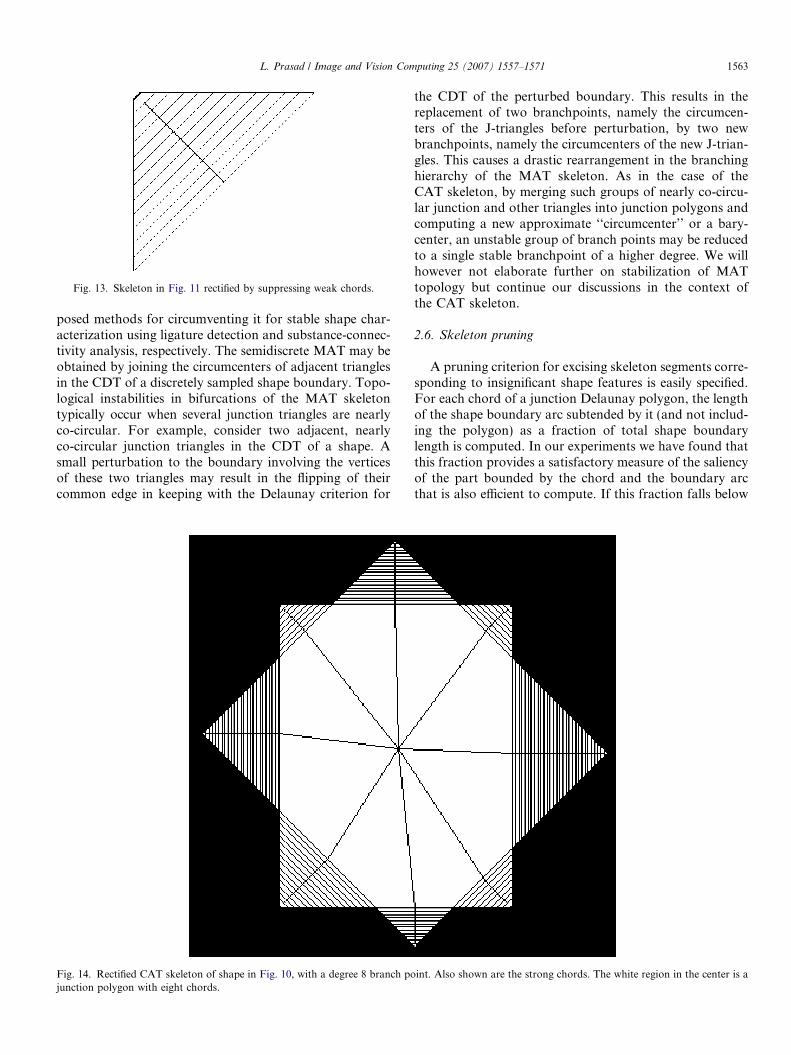
Fig. 13. Skeleton in Fig. 11 rectified by suppressing weak chords.
L. Prasad / Image and Vision Computing 25 (2007) 1557–1571 1563
posed methods for circumventing it for stable shape char-acterization using ligature detection and substance-connec-tivity analysis, respectively. The semidiscrete MAT may beobtained by joining the circumcenters of adjacent trianglesin the CDT of a discretely sampled shape boundary. Topo-logical instabilities in bifurcations of the MAT skeletontypically occur when several junction triangles are nearlyco-circular. For example, consider two adjacent, nearlyco-circular junction triangles in the CDT of a shape. Asmall perturbation to the boundary involving the verticesof these two triangles may result in the flipping of theircommon edge in keeping with the Delaunay criterion for
Fig. 14. Rectified CAT skeleton of shape in Fig. 10, with a degree 8 branch pojunction polygon with eight chords.
the CDT of the perturbed boundary. This results in thereplacement of two branchpoints, namely the circumcen-ters of the J-triangles before perturbation, by two newbranchpoints, namely the circumcenters of the new J-trian-gles. This causes a drastic rearrangement in the branchinghierarchy of the MAT skeleton. As in the case of theCAT skeleton, by merging such groups of nearly co-circu-lar junction and other triangles into junction polygons andcomputing a new approximate ‘‘circumcenter’’ or a bary-center, an unstable group of branch points may be reducedto a single stable branchpoint of a higher degree. We willhowever not elaborate further on stabilization of MATtopology but continue our discussions in the context ofthe CAT skeleton.
2.6. Skeleton pruning
A pruning criterion for excising skeleton segments corre-sponding to insignificant shape features is easily specified.For each chord of a junction Delaunay polygon, the lengthof the shape boundary arc subtended by it (and not includ-ing the polygon) as a fraction of total shape boundarylength is computed. In our experiments we have found thatthis fraction provides a satisfactory measure of the saliencyof the part bounded by the chord and the boundary arcthat is also efficient to compute. If this fraction falls below
int. Also shown are the strong chords. The white region in the center is a
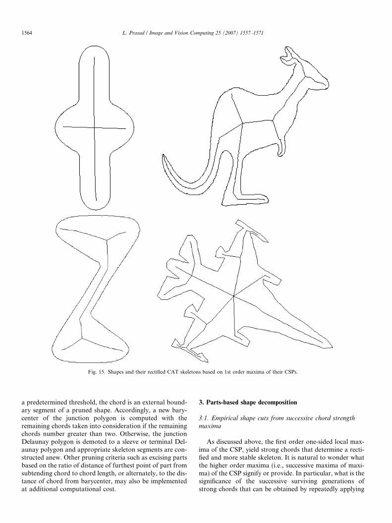
Fig. 15. Shapes and their rectified CAT skeletons based on 1st order maxima of their CSPs.
1564 L. Prasad / Image and Vision Computing 25 (2007) 1557–1571
a predetermined threshold, the chord is an external bound-ary segment of a pruned shape. Accordingly, a new bary-center of the junction polygon is computed with theremaining chords taken into consideration if the remainingchords number greater than two. Otherwise, the junctionDelaunay polygon is demoted to a sleeve or terminal Del-aunay polygon and appropriate skeleton segments are con-structed anew. Other pruning criteria such as excising partsbased on the ratio of distance of furthest point of part fromsubtending chord to chord length, or alternately, to the dis-tance of chord from barycenter, may also be implementedat additional computational cost.
3. Parts-based shape decomposition
3.1. Empirical shape cuts from successive chord strength
maxima
As discussed above, the first order one-sided local max-ima of the CSP, yield strong chords that determine a recti-fied and more stable skeleton. It is natural to wonder whatthe higher order maxima (i.e., successive maxima of maxi-ma) of the CSP signify or provide. In particular, what is thesignificance of the successive surviving generations ofstrong chords that can be obtained by repeatedly applying
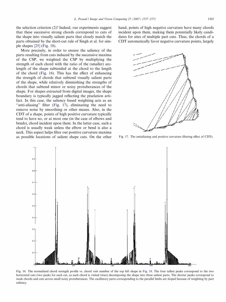
Fig. 17. The antialiasing and positive curvature filtering effect of CDTs.
L. Prasad / Image and Vision Computing 25 (2007) 1557–1571 1565
the selection criterion (2)? Indeed, our experiments suggestthat these successive strong chords correspond to cuts ofthe shape into visually salient parts that closely match theparts obtained by the short-cut rule of Singh et al. for sim-ple shapes [25] (Fig. 18).
More precisely, in order to ensure the saliency of theparts resulting from cuts induced by the successive maximaof the CSP, we weighted the CSP by multiplying thestrength of each chord with the ratio of the (smaller) arc-length of the shape subtended at the chord to the lengthof the chord (Fig. 16). This has the effect of enhancingthe strength of chords that subtend visually salient partsof the shape, while relatively diminishing the strengths ofchords that subtend minor or noisy protuberances of theshape. For shapes extracted from digital images, the shapeboundary is typically jagged reflecting the pixelation arti-fact. In this case, the saliency based weighting acts as an‘‘anti-aliasing’’ filter (Fig. 17), eliminating the need toremove noise by smoothing or other means. Also, in theCDT of a shape, points of high positive curvature typicallytend to have no, or at most one (in the case of elbows andbends), chord incident upon them. In the latter case, such achord is usually weak unless the elbow or bend is also aneck. This aspect helps filter out positive curvature maximaas possible locations of salient shape cuts. On the other
Fig. 16. The normalized chord strength profile vs. chord visit number of thehorizontal cuts (two peaks for each cut, as each chord is visited twice) decompweak chords and cuts across small noisy protuberances. The oscillatory parts csaliency.
hand, points of high negative curvature have many chordsincident upon them, making them potentially likely candi-dates for sites of multiple part cuts. Thus, the chords of aCDT automatically favor negative curvature points, largely
top left shape in Fig. 18. The four tallest peaks correspond to the twoosing the shape into three salient parts. The shorter peaks correspond to
orresponding to the parallel limbs are sloped because of weighting by part

1566 L. Prasad / Image and Vision Computing 25 (2007) 1557–1571
eliminating the need to explicitly specify these points.Indeed, in our experiments we have found that, most often,the above generic properties of chords of a shape’s CDTobviate the need to denoise or compute points of negativecurvature explicitly.
The part saliency-weighted strengths of chords may beused as a measure of overall cut saliency to establish a hier-archy of parts of shapes. Thus, CSP provides not only ameans of rectifying the CAT skeleton (Fig. 15), but also,as an added bonus, a means of decomposing shapes intovisually meaningful parts (Fig. 18).
Fig. 18. Shapes and their decomposition based on fourth order maxi
It is not entirely surprising that strong chords of theCDT of a shape with a discrete boundary should corre-spond to shape part cuts. In the case of a shape with a con-tinuous boundary, a part cut is often distinguished bysignificant flare or narrowing of the shape. The radii ofmaximal discs in the vicinity of such an event increase ordecrease rapidly. In the discrete boundary case, this corre-sponds to strong non-co-circularity of empty circles sub-tended at chords near a potential part cut. However,empty circles that are not co-circular, and with a commonstrong chord, can also result from non-concentric circles of
ma of their CSP. Adjacent parts are shown in alternating shades.
L. Prasad / Image and Vision Computing 25 (2007) 1557–1571 1567
equal radii, as in a tubular region. Evidently, such chordsare not candidates for part cuts and are eliminated in theearly iterations of detection of maxima of the CSP.
Motivated by the potential of strong chords to yield partcuts, we examine the possibility of developing, from firstprinciples, a criterion for identifying part cuts in the chordsof the CDT of a shape specified by a discretely sampledboundary. This leads us to define a notion of an axial deriv-ative of a shape.
3.2. The discrete axial derivative of a shape
A natural way to detect shape parts is to look forrapid changes in the girth of a shape in a direction trans-verse to its axis. To make this idea precise, if C is themedial axis of a continuous shape S, and R = R(c) is afunction that specifies the radii of the maximal inscribedcircles at points c 2 C, then the points of C at which thederivative dR/dc changes rapidly would seem to be thenatural places to make cuts transverse to the axis. Ofcourse, this requires the specification or computation ofthe function R(c), which for most real shapes is eitherunavailable or hard to compute. However, for discreteshapes, the CDT of a shape offers a very easy way ofapproximately computing this derivative directly and alsolocating the cut:
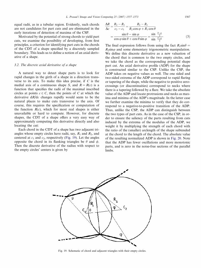
Each chord in the CDT of a shape has two adjacent tri-angles whose empty circles have radii, say, R1 and R2, andcentered at c1 and c2, respectively (Fig. 19). Let the anglesopposite the chord in its flanking triangles be h and /.Then the discrete derivative of the radius with respect tothe empty circles’ centers is given by
Fig. 19. Schematic of chord and adjacen
DRDc¼ R2 � R1
c2 � c1
¼ R2 � R1
R2 cos uþ R1 cos h
¼ sin h� sin ucos u sin hþ cos h sin u
¼sin h�u
2
� �
sin hþu2
� � ð3Þ
The final expression follows from using the fact R1sinh =R2sinu and some elementary trigonometric manipulation.We define this discrete derivative as a new valuation ofthe chord that is common to the two empty circles, andwe take the chord as the corresponding potential shapepart cut. An axial derivative profile (ADP) for the shapeis constructed similar to the CSP. Unlike the CSP, theADP takes on negative values as well. The one sided andtwo-sided extrema of the ADP correspond to rapid flaringor tapering of the shape, while the negative to positive zero-crossings (or discontinuities) correspond to necks wherethere is a tapering followed by a flare. We take the absolutevalue of the ADP and locate protrusions and necks as max-ima and minima of the ADP’s magnitude. In the latter casewe further examine the minima to verify that they do cor-respond to a negative-to-positive transition of the ADP.Thus, unlike the CSP, the ADP can distinguish betweenthe two types of part cuts. As in the case of the CSP, in or-der to ensure the saliency of the parts resulting from cutsinduced by the extrema of the modulus of the ADP, weweight it by multiplying the strength of each chord withthe ratio of the (smaller) arclength of the shape subtendedat the chord to the length of the chord. The absolute valueof the resulting normalized ADP is shown in Fig. 20. Notethat the ADP has fewer oscillations and more monotonicparts, and is zero in the noise-free sections of the parallellimbs.
t triangles with their empty circles.

Fig. 20. The part saliency normalized absolute value of the axial derivative profile (ADP) vs. chord visit number of the top left shape in Fig. 18. As in theCSP, the four tallest peaks correspond to the two horizontal cuts (two peaks for each cut, as each chord is visited twice) decomposing the shape into threesalient parts. The shorter peaks correspond to weak chords and cuts across small noisy protuberances.
1568 L. Prasad / Image and Vision Computing 25 (2007) 1557–1571
We note that the discrete axial derivative incorporateschord strength within it. Indeed, the denominator of theaxial derivative is a measure of co-circularity of the trian-gles adjacent to a chord, while the numerator measuresthe relative discrepancy in the radii, or the flare in the shapeat the chord. The numerator mitigates the oscillations inthe ADP in the monotonic parts of the shape such as par-allel or wedge shaped parts. The CSP oscillates in theseparts as the weak and strong chords tend to alternate.Thus, the ADP can be thought of as an augmentation ofthe CSP.
3.3. Experimental comparison of part cuts from chord
strength and axial derivative
We performed experimental comparisons between thepart saliency-weighted chord strength and the axial deriva-tive as criteria for shape decomposition for digital shapeswith mild to moderate boundary noise. The number of iter-ations of extrema selection was kept at four for each of thethree shapes shown here (Fig. 21). Negative curvature min-ima were not explicitly specified because of the property ofDelaunay triangulations of depriving positive curvaturemaxima of incident chords while at the same time richlysupplying negative curvature minima with fans of chords.
We remark that not all the cuts obtained have the samevalue or part saliency. They are merely the survivors offour stages of iterative extraction of extrema. The experi-ments reveal that the chords corresponding to the ADPmaxima are closer to the visually desired part cuts thanthose of the CSP.
4. Discussion
4.1. Comparison of the chord strength and axial derivative
criteria
The chord strength criterion serves both to rectifychordal axis skeletons as well as provide good shapedecompositions. However, the axial derivative is not usefulfor the purposes of skeletonization as they do not produceas fine a sampling of the shape by chords after the first iter-ation of extracting extrema. Thus, its first order extremacannot support a good skeleton. Nevertheless, the axialderivative criterion did better than the chord strength crite-rion at decomposing shapes.
In our experiments with several shapes, the most salientcuts were obtained after four iterations of extraction of extre-ma in the case of both chord strength and axial derivative cri-teria. However, a more careful study of the chord profiles of

Fig. 21. Experimental results of iteratively applying the chord strength (left) and the axial derivative (right) criteria four times to the chords of the CDTsof the above three shapes with mild to moderate boundary noise.
L. Prasad / Image and Vision Computing 25 (2007) 1557–1571 1569
these criteria is needed to understand the hierarchies for asuccessful and adaptive decomposition scheme. In ourapproach to extrema finding in the chord profiles we used a
method that is equivalent to the watershed transform on a 1-D positive function. Other methods of filtering extremacould possibly yield a more controlled selection of extrema.

1570 L. Prasad / Image and Vision Computing 25 (2007) 1557–1571
4.2. Shapes with holes
Throughout this paper we considered only simply con-nected shapes for ease of exposition. One can easily extendthe methods discussed to 2D shapes with holes as well. Inthe case of shapes with g holes, one can define g + 1 chordprofiles (CSPs or ADPs), one for the contour of each hole,and one for the outer shape contour. The CSPs may thenbe analyzed individually for nth order extrema just as inthe case of a single CSP of a shape without holes. In thecase of a CSP of a shape with holes, a chord will be encoun-tered only once in the CSP if it joins two different contoursand twice if it joins two points on the same contour. Achord is retained as a strong chord of the shape if and onlyif it is a strong chord (nth order maximum) of at least oneCSP. Based on the strong chords obtained thus, one canconstruct rectified CAT skeletons and obtain visually sali-ent decompositions of shapes with holes as well.
Alternatively, one can formulate the problem of findingstrong chords of a discrete shape on the dual graph of itsCDT, where the vertices of the graph represent triangles,and with an edge between each pair of vertices correspond-ing to adjacent triangles in the CDT. Each graph edge canbe weighted with the strength of the chord that separatesthe triangles whose representative vertices the edge con-nects. A watershed segmentation of this graph based onedgeweights then yields extremal graph edges, whose corre-sponding chords are the desired cuts.
4.3. Computational issues
The constrained Delaunay triangulation of a planarshape specified by n points runs in O(n logn) time. The con-struction of the chord profiles and detection of extrema islinear in the number of edges which are 2n � 3 + 3g innumber, where g<n/3 is the number of holes. The connect-ed component analysis on the grouping graph is linear inthe number of vertices (representing the triangles of theshape’s CDT which are n � 2 + 2g in number). Shapepruning is, again, linear in the number of edges. Finally,skeletonization is also linear in the number of edges. Thus,the overall efficiency of our shape decomposition and skel-etonization scheme is high and amenable to real-time appli-cations such as video-based object recognition.
5. Conclusion
In this paper we have described a method of rectifyingchordal axis skeletons of 2D shapes to have smootherbranches and branch points of arbitrary degree. This isachieved by introducing a notion of relative co-circularityof adjacent triangles of constrained Delaunay triangles ofshape. Common edges of such triangles are discounted inthe construction of the skeleton and the corresponding tri-angles are merged into larger polygons. The latter step,when repeatedly applied, also induces shape decomposi-tions into visually salient parts. We also introduced a
refinement of this criterion of decomposition by means ofthe notion of the derivative of a shape with respect to itsaxis. We have experimentally compared these two criteriaput forward by us, and the results indicate that the axialshape derivative is a better criterion for detecting part cutsof shapes. The search for chords that best decompose ashape using the extrema of the chord strengths and the axi-al shape derivative can be improved upon significantly andis part of our ongoing work in shape analysis. Either crite-rion maps the two-dimensional problem of shape decom-position into a one-dimensional problem of analyzingand hierarchically ordering a function’s extrema. The uni-fied approach provided by our method to both skeletoniza-tion and decomposition of shapes is a key contribution ofthis paper.
Acknowledgements
This work has been fully supported by the U. S. DOEunder contract No. W-7405-ENG-36 through an LDRDER (#20030162) research grant. The author would like tothank the reviewers for their helpful comments andcriticism.
References
[1] H. Blum, A transformation for extracting new descriptors of shape.In: Weiant Whaten-Dunn (Ed.), Symp. Models for Speech and VisualForm, MIT Press, 1967.
[2] D. Attali, J.-D. Boisonnat, H. Edelsbrunner, Stability and computa-tion of medial axes—a state-of-the-art report. Available from:<http://www.cs.duke.edu/~edels/BookSurv/MedialAxis.pdf>.
[3] J. August, K. Siddiqi, S. Zucker, Ligature instabilities in theperceptual organization of shape, Proceedings of IEEE CVPR(1999) 42–48.
[4] R. Katz, S. Pizer, Untangling the Blum medial axis transform, IJCVSpecial UNC-MIDAG issue, vol. 55 (2/3), 2003, pp 139–153.
[5] G. Sanniti di Baja, E. Thiel, (3,4)-Weighted skeleton decompositionfor pattern representation and description, Pattern Recognition 27 (8)(1994) 1039–1049.
[6] G. Borgefors, G. Ramella, G. Sanniti di Baja, Hierarchical decom-position of multiscale skeletons, IEEE Transactions on PAMI 23 (11)(2001).
[7] R.L. Ogniewicz, Skeleton-space: a multiscale shape descriptioncombining region and boundary information. In: Proc. IEEE CVPR,Seattle, WA, June 1994.
[8] D. Attali, A. Montanvert, Computing and simplifying 2D and 3Dcontinuous skeletons, Computer Vision and Image Understanding 67(1997).
[9] L. Prasad, Morphological Analysis of Shapes, CNLS Newsletter, No.139, July 1997, LALP-97-010-139, Center for Nonlinear Studies, LosAlamos National Laboratory.
[10] L. Prasad, R.L. Rao, G. Zweig, Skeletonization of shapes usingDelaunay triangulations, Fifth SIAM Conference on GeometricDesign, Nashville, TN, November 1997.
[11] L. Prasad, R.L. Rao, A Geometric Transform for ShapeFeature Extraction. In: Proc. SPIE, vol. 4117, Vision GeometryIX, 2000.
[12] T. Igarashi, S. Matsuoka, H. Tanaka, Teddy: A Sketching Interfacefor 3D Freeform Design, ACM SIGGRAPH’99, Los Angeles, CA,1999, pp. 409–416.
[13] P. Felzenszwalb, Representation and detection of deformable shapes.In: Proc. CVPR, vol. 1, 2003, pp. 102–108.

L. Prasad / Image and Vision Computing 25 (2007) 1557–1571 1571
[14] J. Arvo, K. Novins, Smart Text: A Synthesis of Recognition andMorphing AAAI Spring Symposium on Smart Graphics, Stanford,California, March 2000, pp. 140–147.
[15] S. Yamakawa, K. Shimada, Quad-Layer: Layered Quadrilater-al Meshing of Narrow Two-Dimensional Domains by BubblePacking and Chordal Axis Transform, ASME/DETC/DAC,2001.
[16] J.E. Goodman, J. O’Rourke (Eds.), Handbook of Discrete andComputational Geometry, CRC Press, 1997.
[17] L. Prasad, A. Skourikhine, B. Schlei, Feature-based syntactic andmetric shape recognition. In: Proc. SPIE, Vision Geometry IX, vol.4117, 2000.
[18] L. Shapiro, R. Haralick, Decomposition of two-dimensional shapesby graph-theoretic clustering, IEEE Transactions on PAMI 1 (1979)10–20.
[19] T.O. Binford, Visual perception by computer, IEEE Conference onSystems and Control, December 1971.
[20] H. Freeman, Shape description via the use of critical points, PatternRecognition 10 (1978) 159–166.
[21] W.A. Richards, J. Koenderink, D. Hoffman, Inferring three dimen-sional shapes from two-dimensional silhouettes, Journal of OpticalSociety of America 4 (7) (1987) 1168–1175.
[22] F. Attneave, Some informational aspects of visual perception,Psychology Review 61 (1954) 183–193.
[23] D.D. Hoffman, W.A. Richards, Parts of recognition, Cognition 18(1985) 65–96.
[24] K. Siddiqi, B.B. Kimia, Parts of Visual Form: ComputationalAspects, IEEE Transactions on PAMI 17 (3) (1995).
[25] M. Singh, G. Seyranian, D. Hoffman, Parsing silhouettes: the short-cut rule, Perception and Psychophysics, Cognition 61 (1999) 636–660.
[26] L. Prasad, Rectification of the chordal axis transform and a newcriterion for shape decomposition. In: Proceedings of the 12thInternational Conference on Discrete Geometry for ComputerImagery, Poitiers, France, Lecture Notes in Computer Science, vol.3429, April 2005, pp. 263–275.
[27] L. Vincent, P. Soille, Watersheds in digital spaces: an efficientalgorithm based on immersion simulations, IEEE Transactions ofPAMI 13 (6) (1991) 583–598.