recovery of linseed oil dispersed within an oil-in-water...
TRANSCRIPT

Rh
La
b
a
ARRAA
KODRHD
1
pcweanso
btopltcr
ET
0d
Journal of Membrane Science 342 (2009) 70–79
Contents lists available at ScienceDirect
Journal of Membrane Science
journa l homepage: www.e lsev ier .com/ locate /memsci
ecovery of linseed oil dispersed within an oil-in-water emulsion usingydrophilic membrane by rotating disk filtration system
ina Li a, Luhui Ding a,∗, Zhenghuan Tu a, Yinhua Wan b, Danièle Clausse a, Jean-Louis Lanoisellé a
EA 4297 TIMR, University of Technologie of Compiegne, 60205 Compiegne Cedex, FranceThe National Key Laboratory of Biochemical Engineering, Institute of Process Engineering, Chinese Academy of Sciences, Beijing 100080, PR China
r t i c l e i n f o
rticle history:eceived 2 April 2009eceived in revised form 9 June 2009ccepted 13 June 2009vailable online 21 June 2009
eywords:
a b s t r a c t
The purpose of this paper is to investigate a method to recover the linseed oil from oil-in-water (O/W)emulsion by a rotating disk filtration system. The influence of transmembrane pressure (TMP), diskrotating speed, and disk geometry on permeate flux and oil recovery has been studied. Hydrophilicpolyvinylidene difluoride (PVDF) membranes with average pore size 0.15 �m and polyethersulfone (PES)membranes with 50 kDa molecular weight cut off (MWCO) were used. The results showed that the rotat-ing disk module can produce high permeate fluxes. The highest permeate fluxes were obtained when
il-in-water emulsionynamic filtrationotating diskydrophilic membraneemulsification
using a rotating disk equipped with vanes, which generated the largest shear rates at the membrane.This study demonstrated that hydrophilic membranes were suitable for demulsification of linseed oil-in-water emulsion. The linseed oil droplets in the emulsions could be separated by concentration tests dueto the coalescence of oil droplets in the concentration polarization layer. For an initial oil mass of 46.5 g,35.2 g supernatant oil was obtained owing to oil droplets coalescence. This supernatant oil representeda recovery of 76%. The rotating disk with vanes consumed less specific energy than smooth disk in the
concentration tests.. Introduction
Oil/water separation is very important in many technologicalrocesses such as food, pharmaceutical, petrochemical, metallurgi-al, cosmetic and dyestuff industries, where large amounts of wasteater containing oil are frequently generated. However, the recov-
ry of disperse phase and the reuse or discharge continuous phasere the main problems encountered in these processes. Many tech-iques [1–6] were used to solve these problems, such as ultrasoniceparation, coagulation, flocculation, synergistic effect of salt andzone, electric field, air flotation and membrane filtration.
Due to the higher efficiency and lower energy cost of mem-rane demulsification, membrane filtration is more and more usedo treat emulsions. Lipp et al. [7] described the oil separation foril-in-water (O/W) emulsion by ultrafiltration. They found that theermeate, which contained a few very large drops caused by coa-
escence within the membrane, had a wider size distribution thanhe feed. Hong et al. [8] investigated the factors affecting membraneoalescence of stable O/W emulsions and indicated that the shearates inside the membrane pores played a key role during mem-
∗ Corresponding author at: University of Technologie of Compiegne, Biologicalngineering Department, B.P. 20529, 60205 Compiegne Cedex, France.el.: +33 3 4423 4634; fax: +33 3 4423 7942.
E-mail address: [email protected] (L. Ding).
376-7388/$ – see front matter © 2009 Elsevier B.V. All rights reserved.oi:10.1016/j.memsci.2009.06.023
© 2009 Elsevier B.V. All rights reserved.
brane coalescence. Hlavacek [9] pointed out that demulsificationoccurred when the emulsion was permeated through some micro-filtration membranes and the membrane acted here as a coalescingagent. Daiminger et al. [10] found that during the flow of disper-sion through thin microporous hydrophobic membranes with poresize similar to drop size, a spontaneous droplet enlargement takesplace.
Most published researches concern O/W emulsions which canbe demulsificated by hydrophobic membrane and W/O emulsionswhich can be demulsificated by hydrophilic membrane. Thesedemulsifications are based on the ability of the transmembranepressure to force the dispersed phase pass through a membraneinto the permeate (continuous phase). This is because the disperseddroplets are deformable and can be squeezed through the pores.The coalescence within the pores depended on the applied pres-sure. The droplets of the dispersed phase in permeate, which aremuch larger than that in retentate, could be easily separated bygravity. Strictly speaking, these processes are not a filtration tech-nique as the membrane does not retain any particular phase [9]. Thewhole emulsion passes through the membrane and the membraneacts as a coalescing medium. However, Lin and Lan [11], Li et al.
[12] and Moulai-Mostefa et al. [13] proposed another way. Theyused hydrophilic membrane to separate O/W emulsion. Lin andLan [11] employed semi-batch ultrafiltration (UF) and ion exchangeprocess to treat the waste oil in water emulsion. They examinedthe performance of hydrophilic and hydrophobic UF membranes
brane Science 342 (2009) 70–79 71
wb[sw1twtmbmbsflam
rttrmsrcbltvfvttppthwuac(
frtbtsfr(e6opros
atepp
L. Li et al. / Journal of Mem
ith different pore sizes. They indicated that the hydrophilic mem-rane was better for the present UF treatment purpose. Li et al.12] developed a hydrophilic hollow fiber UF membrane for O/Weparation. The results showed that oil retention of the membraneas over 99% and the oil concentration in permeate was below
0 mg L−1 (against 800 mg L−1 in feed). Moulai-Mostefa et al. [13]reated O/W emulsion by the membrane of PES 50 kDa moleculareight cut off (MWCO). The oil rejection coefficient was 99.5%. In
he case of O/W separation, it is widely recognized that hydrophilicaterials are less sensitive to adsorption compared to hydropho-
ic ones, so it may be considered as a key solution to reduce theembrane fouling. For instance, Hlavacek [9] used a hydropho-
ic membrane (Enka 2E PPHF) made of polypropylene with a poreize of 0.2 �m to separate oil from O/W emulsion with a permeateux of 50 L h−1 m−2 whereas Moulai-Mostefa et al. [13] obtainedpermeate flux of 98 L h−1 m−2 using a 50 kDa PES hydrophilicembrane.
It is well known that high shear rate at the membrane couldeduce concentration polarization and cake formation during filtra-ion. Dynamic filtration permits to produce very high shear rate athe membrane surface and has been recently investigated by manyesearchers. Dal-Cin et al. [14] used a commercial centrifugal rotary
embrane module for ultrafiltration of O/W emulsions. The resultshowed that this module could operate at extremely high shearates (>105 s−1) which can be set independent of the bulk recir-ulation rate. The back transport mechanism controlling oil dropletehavior at the membrane surface was primarily confounded by the
arge droplet size range (50–3000 nm). Brou et al. [15] investigatedhe performance of a rotating disk module with straight vanes ofarious heights using baker yeast suspensions as a test fluid. Theyound that the permeate flux was proportional to kω (product ofelocity factor and angular velocity) for both 2 and 6 mm vanes ando about (kω)0.864 for a smooth disk. Jaffrin et al. [16] comparedhe effects of various hydrodynamic parameters (transmembraneressure, shear rate, fluid viscosity and solute concentration) on theermeate flux provided by two different rotating disk filtration sys-ems. Their data suggested that the flux could be increased to veryigh levels by increasing rotation speed or by equipping the diskith large vanes. Bouzerar et al. [17,18] used a rotating disk mod-
le for microfiltration of suspensions of calcium carbonate particlesnd expressed the mean permeate flux as a function of particle con-entration, disk rotation speed and mean transmembrane pressureTMP).
The lubricants used in automobile industry are mainly obtainedrom petroleum. They pollute soils and underground water. Theecent environmental standards call for reduction of pollutant forhe sake of sustainable development. The substitution of fossil oily vegetable oil, which is biodegradable and renewable, could con-ribute to solve this problem. Our group develops a process withoutolvent [19] for extracting almost all oil present in seeds with theollowing stages: (1) mechanical pressing of the vegetable seeds toecover 70% of the initial oil and to obtain the oil meal (press-cake);2) extraction of the remained oil in the oil meal by high voltagelectrical discharges (HVED) in aqueous solution (for linseed meal,8% linseed oil present in meal could be extracted in this step), theil extracted forms O/W emulsions; (3) centrifugation of the sus-ension (separation of linseed O/W emulsions, polysaccharides andesidues); (4) demulsification by dynamic filtration to recover theil present in the emulsion and also to reuse water in the HVEDtep.
Since demulsification is a key step in ensuring high oil recovery
nd low oil concentration in the permeate (effluent), the purpose ofhis paper is to examine the feasibility of recovering oil from O/Wmulsion by dynamic membrane filtration system. The filtrationerformance of the rotating disk module at various hydrodynamicarameters and the specific energy consumption were investigated.Fig. 1. Calibration curve of COD with turbidity. The symbols represent the averagemeasured COD of two tests.
The possible mechanism of demulsification in the case of O/Wemulsion by hydrophilic membrane was also discussed.
2. Materials and methods
2.1. Test fluid
The fluid used in this study was an O/W emulsion (linseed oilin water). A mixture of linseed oil (Vandeputte S.A., Mouscron,Belgium) and demineralized water was placed in an ice bath andtreated by the ultrasonic generator (Hielscher GmbH Stuttgart, Ger-many) for 40 min. The vibrating frequency and the input power ofthe ultrasonic waves were set at 24 kHz and 400 W, respectively.The linseed oil in aqueous could form spontaneously O/W emul-sion due to its natural surfactant. The oil concentration of emulsionwas 1.50 ± 0.05% (w/w).
The emulsion has been characterised by an optical immersionmicroscope (Nikon 513116, Tokyo, Japan) equipped with a camera(Color video camera, SONY SSC-DC58AP, Tokyo, Japan). The diam-eter of oil droplets was measured by laser granulometry (Zetasizer3000HS, Malvern Instruments, Worcs., UK). The chemical oxygendemand (COD) of the feed was 36.5 ± 1.2 g L−1, which was measuredby Nanocolor kits (Macherey-Nagel, Hoerdl, France) and PF-11photometer. This COD analysis took at least 3 h for each samplewhereas turbidity could be measured during filtration experiments.Since the calibration curve of COD with turbidity (Fig. 1) pre-sented a good linearity (coefficient of determination was 0.98),the COD was calculated by the following regression equation: COD(mg L−1) = 1.53 × turbidity (NTU). The turbidity was measured bythe turbidimeter (HACH Company, Loveland, CO, USA).
2.2. Membranes
The membranes used were polyvinylidene difluoride (PVDF)microfiltration membrane (Alfa Laval, Nakskov, Denmark, pore sizeof 0.15 �m) and polyethersulfone (PES) ultrafiltration membrane(Microdyn-Nadir GmbH, Wiesbaden, Germany, with 50 kDa molec-ular weight cut off). For cleaning the membrane, the circuit was
first rinsed with 10 L demineralized water, and then washed with5 L of Ultrasil P3-25F solution (0.5% in demineralized water, Henkel,Germany) at 20 ◦C for 15 min and rinsed again with demineralizedwater until the pH = 7 before and after each test.
7 brane
2
TflRcrtgsi0pdrw4uIr
2 L. Li et al. / Journal of Mem
.3. Experimental set-up
A schematic of the rotating disk system is presented in Fig. 2(a).his system was designed and built in our laboratory [17,18]. Aat membrane, with an effective area of 188 cm2 (outer radius1 = 7.75 × 10⁻² m, inner radius R2 = 1.75 × 10⁻² m), was fixed on theover of the cylindrical housing in front of the disk. The disk canotate at adjustable speeds, ranging from 500 to 2750 rpm. Twoypes of disks were utilized, a disk equipped with eight rectan-ular vanes (6 mm in height and 2 mm in width, Fig. 2(a)) and amooth disk (flat on both sides). The experimental set-up is shownn Fig. 2(b). In microfiltration (MF) tests, the dead volume was.65 L. The feed of 3 L emulsion was introduced by a Masterflexeristaltic pump with a flow rate of 0.5 L min−1. In UF tests, theead volume was 2 L. 8 L emulsion (ensure to obtain the same oilecovery) was fed at a flow rate of 0.5 L min−1 by a pump equippedith a HYDRA-CELL membrane. In MF tests, the maximum TMP was
00 kPa. So a Masterflex peristaltic pump with smaller tubing wassed in MF experiments to obtain a minimum dead volume (0.65 L).
n UF experiments, the TMP rose up to 1000 kPa, to satisfy this TMPequirement, both the HYDRA-CELL membrane pump and the tub-
Fig. 2. (a) Schematic of experimental set-up.
Science 342 (2009) 70–79
ing used were larger (2 L). The retentate was evacuated through thehollow shaft and permeate was collected from a tap located at thetop of the front plate. The peripheral pressure (Pc) was measuredat the top of the cylindrical housing by a Validyne DP15 pressuretransducer. The TMP could be regulated by the valve placing onthe outlet retentate tubing. The permeate flow rate was measuredby collecting the permeate in a beaker continuously weighted onan electronic scale (Sartorius, Germany) connected to a microcom-puter calculating the derivative of the collected volume with respectto time. All experiments were performed at 20 ◦C.
In our study, two kinds of conditions are used. One is “concentra-tion test” (Sections 3.1 and 3.2), which means the permeate is notrecycled and the retentate in the tank is concentrated. The otherone is carried out at “constant concentration conditions” (Sections3.3 and 3.4), which means that the permeate was recycled to keepoil concentration constant in the tank. In concentration tests, theexperiments were stopped when there were no fluid in the tank,
giving a maximum VRR (Volume Reduction Ratio). The VRR wasdefined as the ratio of initial volume to final volume after filtration.In the tests of constant concentration conditions, the feed volumewas 6 L.(b) Schematic of rotating disk module.
L. Li et al. / Journal of Membrane Science 342 (2009) 70–79 73
Table 1Mean shear rate on the membrane for smooth disk and disk with 6 mm vanes.
N (rpm)
500 1000 1500 2000 2500 2750
�
2s
mdlTvdc
p
wic(fvd
mt
p
wh
e
�
w
E
�
v
3
3
tmowtf
J
wv
of the concentration tests. The initial feed and concentrated samplewith supernatant oil were shown in Fig. 4. A separating funnel wasused to separate the supernatant oil from the retentate. Thus, the
m (104 s−1)Smooth disk 0.40 1.41 2.93 4.91 7.31 8.70Disk with 6 mm vanes 1.56 5.45 11.30 19.00 28.37 33.69
.4. Calculations of transmembrane pressure and membranehear rate
Bouzerar et al. [17,18] have described the flow field between theembrane and a rotating flat disk. Since the axial gap between the
isk and the membrane was larger than 5 mm, the flow of boundaryayer type is turbulent except at low speeds and in the central part.he inviscid core between the boundary layers rotates at the angularelocity kω, where k (less than 1) is a velocity coefficient whichepends on disk geometry. The pressure distribution in the inviscidore is given by Bernoulli’s equation
= 12
�k2ω2r2 + p0 (1)
here � denotes the fluid density, k is the velocity coefficient, ωs the angular velocity, r is the radius and p0 is the pressure at theenter and also equal to the pressure when the disk is at rest. Eq.1) permits to determine by regression the velocity coefficient krom peripheral pressure measurements taken at various angularelocities. k was found to be 0.42 for a smooth disk and 0.89 for aisk equipped with 6 mm vanes.
Since the permeate is collected at atmospheric pressure, theean transmembrane pressure (TMP) ptm is obtained by integra-
ion of Eq. (1) over the membrane area as [18]
tm = pc − 14
�k2ω2R2 (2)
here pc is the peripheral pressure at r = R = 7.75 × 10⁻² m. Theousing inner radius is equal to the outer radius of the membrane.
The shear rate on the membrane has been calculated by Bouzerart al. [17,18] in the turbulent regime to be
wt = 0.0296�−0.8(kω)1.8r1.6 (3)
here � is the fluid kinetic viscosity and k is the velocity factor.The mean shear rate over the membrane is calculated integrating
q. (3) over the membrane up to the disk radius to be given by
m = 0.0164�−0.8(kω)1.8R1.6d (4)
Table 1 shows that the mean shear rates on the membrane atarious speeds for smooth disk and disk equipped with 6 mm vanes.
. Results and discussion
.1. MF concentration tests
The variation of permeate flux as a function of time for concen-ration tests using a rotating disk equipped with 6 mm vanes and a
embrane of PVDF 0.15 �m is shown in Fig. 3. Tests were carriedut at a rotation speed of 2500 rpm and TMP of 100 kPa. Three testsere performed. A new membrane was used in the 1st test. Then,
his membrane was washed once for the 2nd test and washed againor the 3rd test. The average flux Jav was defined as
av = 60VF
t A(5)
here VF is the total permeate volume obtained during time inter-al t, and A is the membrane surface area.
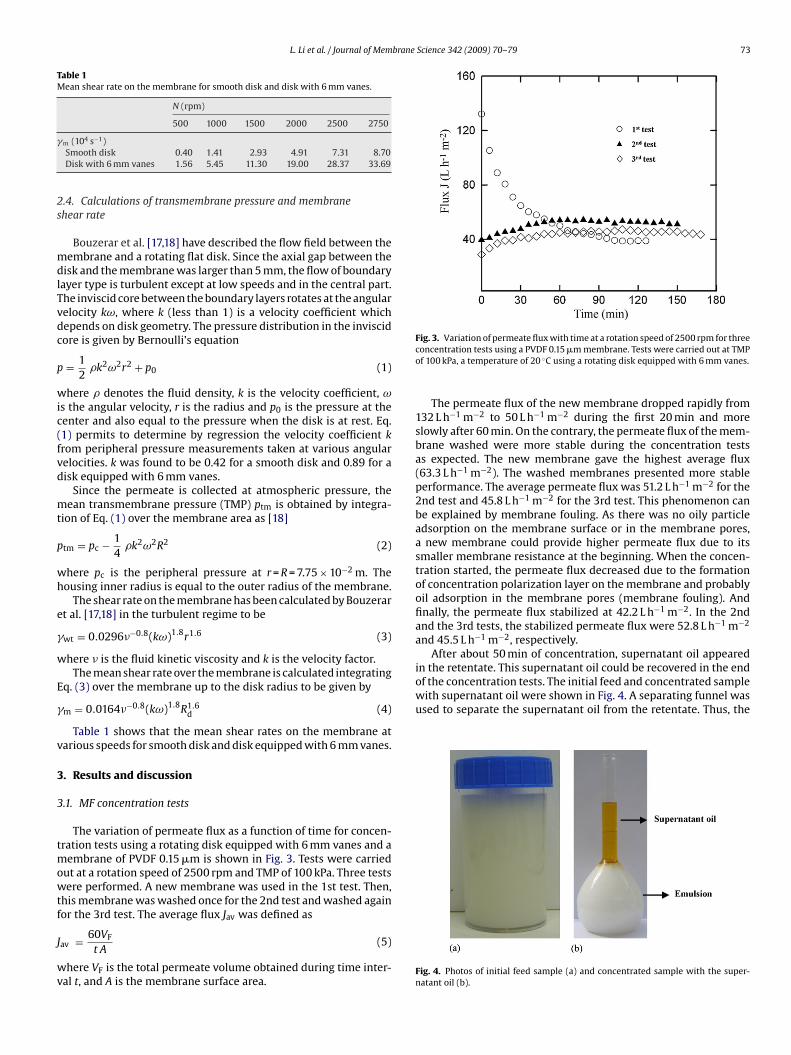
Fig. 3. Variation of permeate flux with time at a rotation speed of 2500 rpm for threeconcentration tests using a PVDF 0.15 �m membrane. Tests were carried out at TMPof 100 kPa, a temperature of 20 ◦C using a rotating disk equipped with 6 mm vanes.
The permeate flux of the new membrane dropped rapidly from132 L h−1 m−2 to 50 L h−1 m−2 during the first 20 min and moreslowly after 60 min. On the contrary, the permeate flux of the mem-brane washed were more stable during the concentration testsas expected. The new membrane gave the highest average flux(63.3 L h−1 m−2). The washed membranes presented more stableperformance. The average permeate flux was 51.2 L h−1 m−2 for the2nd test and 45.8 L h−1 m−2 for the 3rd test. This phenomenon canbe explained by membrane fouling. As there was no oily particleadsorption on the membrane surface or in the membrane pores,a new membrane could provide higher permeate flux due to itssmaller membrane resistance at the beginning. When the concen-tration started, the permeate flux decreased due to the formationof concentration polarization layer on the membrane and probablyoil adsorption in the membrane pores (membrane fouling). Andfinally, the permeate flux stabilized at 42.2 L h−1 m−2. In the 2ndand the 3rd tests, the stabilized permeate flux were 52.8 L h−1 m−2
and 45.5 L h−1 m−2, respectively.After about 50 min of concentration, supernatant oil appeared
in the retentate. This supernatant oil could be recovered in the end
Fig. 4. Photos of initial feed sample (a) and concentrated sample with the super-natant oil (b).
74 L. Li et al. / Journal of Membrane Science 342 (2009) 70–79
F memV entratd oil dro
o
O
awmosNdtta
bt
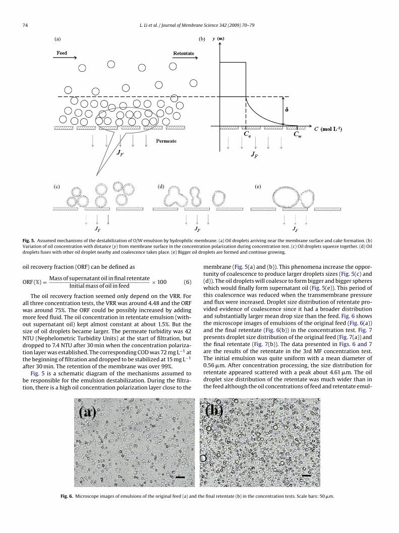
ig. 5. Assumed mechanisms of the destabilization of O/W emulsion by hydrophilicariation of oil concentration with distance (y) from membrane surface in the concroplets fuses with other oil droplet nearby and coalescence takes place. (e) Bigger
il recovery fraction (ORF) can be defined as
RF (%) = Mass of supernatant oil in final retentateInitial mass of oil in feed
× 100 (6)
The oil recovery fraction seemed only depend on the VRR. Forll three concentration tests, the VRR was around 4.48 and the ORFas around 75%. The ORF could be possibly increased by addingore feed fluid. The oil concentration in retentate emulsion (with-
ut supernatant oil) kept almost constant at about 1.5%. But theize of oil droplets became larger. The permeate turbidity was 42TU (Nephelometric Turbidity Units) at the start of filtration, butropped to 7.4 NTU after 30 min when the concentration polariza-ion layer was established. The corresponding COD was 72 mg L−1 at
he beginning of filtration and dropped to be stabilized at 15 mg L−1fter 30 min. The retention of the membrane was over 99%.Fig. 5 is a schematic diagram of the mechanisms assumed to
e responsible for the emulsion destabilization. During the filtra-ion, there is a high oil concentration polarization layer close to the
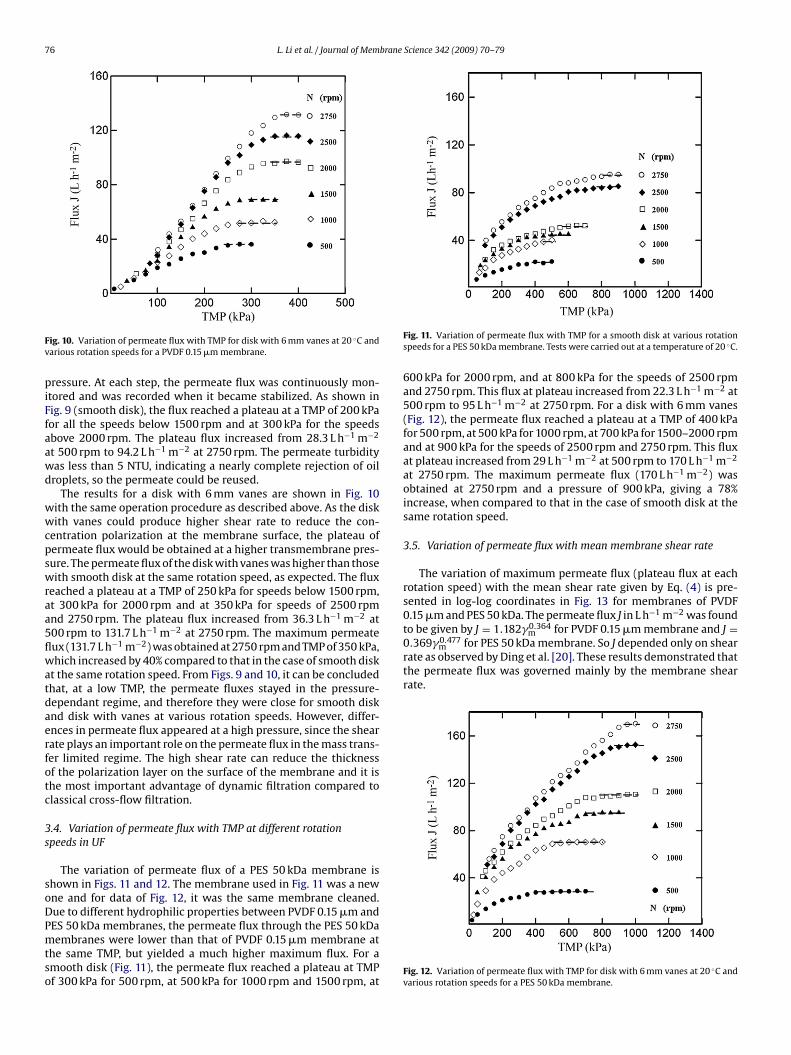
Fig. 6. Microscope images of emulsions of the original feed (a) and the
brane. (a) Oil droplets arriving near the membrane surface and cake formation. (b)ion polarization during concentration test. (c) Oil droplets squeeze together. (d) Oilplets are formed and continue growing.
membrane (Fig. 5(a) and (b)). This phenomena increase the oppor-tunity of coalescence to produce larger droplets sizes (Fig. 5(c) and(d)). The oil droplets will coalesce to form bigger and bigger sphereswhich would finally form supernatant oil (Fig. 5(e)). This period ofthis coalescence was reduced when the transmembrane pressureand flux were increased. Droplet size distribution of retentate pro-vided evidence of coalescence since it had a broader distributionand substantially larger mean drop size than the feed. Fig. 6 showsthe microscope images of emulsions of the original feed (Fig. 6(a))and the final retentate (Fig. 6(b)) in the concentration test. Fig. 7presents droplet size distribution of the original feed (Fig. 7(a)) andthe final retentate (Fig. 7(b)). The data presented in Figs. 6 and 7are the results of the retentate in the 3rd MF concentration test.
The initial emulsion was quite uniform with a mean diameter of0.56 �m. After concentration processing, the size distribution forretentate appeared scattered with a peak about 4.61 �m. The oildroplet size distribution of the retentate was much wider than inthe feed although the oil concentrations of feed and retentate emul-final retentate (b) in the concentration tests. Scale bars: 50 �m.

L. Li et al. / Journal of Membrane Science 342 (2009) 70–79 75
sLttpa
3
mF1ssg4Us4nc4N7e
ing rotating speed (from 2750 rpm to 500 rpm). At each rotatingspeed, filtration began with the retentate valve fully open (min-imal TMP) for 5 min, and then the valve was progressively shutdown to increase TMP. Each point on the graph was taken aftera stabilized permeate flux keeping at least 5 min at a constant
Fig. 7. Droplet size distribution of original feed (a) and final retentate (b).
ion were similar. These phenomena have also been observed byipp et al. [7]. Droplets in the retentate exhibited a wider size dis-ribution and substantially larger mean droplet size than those inhe feed showing direct evidence of coalescence in the retentate. Inractice, visible deposits of oil were observed on the membranesfter several runs of the experiments.
.2. UF concentration tests
Three similar tests as in Section 3.1 were carried out with theembrane of PES 50 kDa at 900 kPa and 2500 rpm. As shown in
ig. 8, the permeate flux of the new membrane declined from48 L h−1 m−2 to 55 L h−1 m−2 in 60 min and decreased much morelowly after 180 min. Similar trends were observed in the sub-equent tests with the washed membrane. The new membraneave the highest average flux (50 L h−1 m−2). The average flux was5 L h−1 m−2 for the 2nd test and 40 L h−1 m−2 for the 3rd test. So inF, the average flux decreased similarly to that in MF. Besides, the
tabilized fluxes in UF for the 1st, the 2nd and the 3rd tests were1 L h−1 m−2, 42 L h−1 m−2 and 39 L h−1 m−2, respectively. A super-atant oil phase appeared in the retentate after about 60 min of
oncentration. For all three concentration tests, the VRR was aroundand the ORF was around 68%. The permeate turbidity was 35TU at the beginning of filtration, but dropped to 3.2 NTU after5 min when the concentration polarization layer was probablystablished. The corresponding COD was 60 mg L−1 at the begin-
Fig. 8. Variation of permeate flux with time at a rotation speed of 2500 rpm for threeconcentration tests using a PES 50 kDa membrane. Tests were carried out at TMP of900 kPa, a temperature of 20 ◦C using a rotating disk equipped with 6 mm vanes.
ning of filtration and dropped to 8.5 mg L−1 after 30 min. There wasa little difference of the permeate COD comparing to MF. The oilretention of the membrane was still kept very high, more than 99%as that in the case of MF. It was not possible to observe any differencein the oil retention between MF and UF in our study.
3.3. Variation of permeate flux with TMP at different rotationspeeds in MF
The variation of permeate flux using the rotating disk moduleequipped with a smooth disk and a disk with 6 mm vanes withPVDF 0.15 �m membrane is displayed in Figs. 9 and 10. At thebeginning of the experiment, the operating conditions were fixedat 2000 rpm and the retentate valve open (in this case, TMP were22 kPa for smooth disk and 50 kPa for disk with vanes) for 20 min.Then the experiments were carried out with gradually decreas-
Fig. 9. Variation of permeate flux with TMP for a smooth disk at various rotationspeeds and 20 ◦C for a PVDF 0.15 �m membrane.
76 L. Li et al. / Journal of Membrane Science 342 (2009) 70–79
Fv
piFfaawd
wwcpswraa5flwatdaerfotc
3s
soDPmtso
to be given by J = 1.182�m for PVDF 0.15 �m membrane and J =0.369�0.477
m for PES 50 kDa membrane. So J depended only on shearrate as observed by Ding et al. [20]. These results demonstrated thatthe permeate flux was governed mainly by the membrane shearrate.
ig. 10. Variation of permeate flux with TMP for disk with 6 mm vanes at 20 ◦C andarious rotation speeds for a PVDF 0.15 �m membrane.
ressure. At each step, the permeate flux was continuously mon-tored and was recorded when it became stabilized. As shown inig. 9 (smooth disk), the flux reached a plateau at a TMP of 200 kPaor all the speeds below 1500 rpm and at 300 kPa for the speedsbove 2000 rpm. The plateau flux increased from 28.3 L h−1 m−2
t 500 rpm to 94.2 L h−1 m−2 at 2750 rpm. The permeate turbidityas less than 5 NTU, indicating a nearly complete rejection of oilroplets, so the permeate could be reused.
The results for a disk with 6 mm vanes are shown in Fig. 10ith the same operation procedure as described above. As the diskith vanes could produce higher shear rate to reduce the con-
entration polarization at the membrane surface, the plateau ofermeate flux would be obtained at a higher transmembrane pres-ure. The permeate flux of the disk with vanes was higher than thoseith smooth disk at the same rotation speed, as expected. The flux
eached a plateau at a TMP of 250 kPa for speeds below 1500 rpm,t 300 kPa for 2000 rpm and at 350 kPa for speeds of 2500 rpmnd 2750 rpm. The plateau flux increased from 36.3 L h−1 m−2 at00 rpm to 131.7 L h−1 m−2 at 2750 rpm. The maximum permeateux (131.7 L h−1 m−2) was obtained at 2750 rpm and TMP of 350 kPa,hich increased by 40% compared to that in the case of smooth disk
t the same rotation speed. From Figs. 9 and 10, it can be concludedhat, at a low TMP, the permeate fluxes stayed in the pressure-ependant regime, and therefore they were close for smooth disknd disk with vanes at various rotation speeds. However, differ-nces in permeate flux appeared at a high pressure, since the shearate plays an important role on the permeate flux in the mass trans-er limited regime. The high shear rate can reduce the thicknessf the polarization layer on the surface of the membrane and it ishe most important advantage of dynamic filtration compared tolassical cross-flow filtration.
.4. Variation of permeate flux with TMP at different rotationpeeds in UF
The variation of permeate flux of a PES 50 kDa membrane ishown in Figs. 11 and 12. The membrane used in Fig. 11 was a newne and for data of Fig. 12, it was the same membrane cleaned.ue to different hydrophilic properties between PVDF 0.15 �m and
ES 50 kDa membranes, the permeate flux through the PES 50 kDaembranes were lower than that of PVDF 0.15 �m membrane athe same TMP, but yielded a much higher maximum flux. For amooth disk (Fig. 11), the permeate flux reached a plateau at TMPf 300 kPa for 500 rpm, at 500 kPa for 1000 rpm and 1500 rpm, at
Fig. 11. Variation of permeate flux with TMP for a smooth disk at various rotationspeeds for a PES 50 kDa membrane. Tests were carried out at a temperature of 20 ◦C.
600 kPa for 2000 rpm, and at 800 kPa for the speeds of 2500 rpmand 2750 rpm. This flux at plateau increased from 22.3 L h−1 m−2 at500 rpm to 95 L h−1 m−2 at 2750 rpm. For a disk with 6 mm vanes(Fig. 12), the permeate flux reached a plateau at a TMP of 400 kPafor 500 rpm, at 500 kPa for 1000 rpm, at 700 kPa for 1500–2000 rpmand at 900 kPa for the speeds of 2500 rpm and 2750 rpm. This fluxat plateau increased from 29 L h−1 m−2 at 500 rpm to 170 L h−1 m−2
at 2750 rpm. The maximum permeate flux (170 L h−1 m−2) wasobtained at 2750 rpm and a pressure of 900 kPa, giving a 78%increase, when compared to that in the case of smooth disk at thesame rotation speed.
3.5. Variation of permeate flux with mean membrane shear rate
The variation of maximum permeate flux (plateau flux at eachrotation speed) with the mean shear rate given by Eq. (4) is pre-sented in log-log coordinates in Fig. 13 for membranes of PVDF0.15 �m and PES 50 kDa. The permeate flux J in L h−1 m−2 was found
0.364
Fig. 12. Variation of permeate flux with TMP for disk with 6 mm vanes at 20 ◦C andvarious rotation speeds for a PES 50 kDa membrane.

L. Li et al. / Journal of Membrane Science 342 (2009) 70–79 77
Fd
3
icTttbnbiood
ho
P
Fa
PES 50 kDa membrane.
ig. 13. Variation of maximum permeate flux with mean shear rate for two types ofisks of PVDF 0.15 �m and PES 50 kDa membranes.
.6. Energy considerations
The energy consumed to drive the disk is very important forts industrial application. In this study, a large part of the electri-al power supplied is consumed by friction of the rotating shaft.hus, to eliminate the shaft friction, we have subtracted the elec-rical power necessary to drive the system without fluid Pev fromhe power at the same speed in the filtration test Pe, as describedy Brou et al. [15] and Ding et al. [20]. The power difference (oret power PN = P − Pev) corresponding to the friction forces exertedy the fluid on the disk was presented in Fig. 14. The net power
ncreased with the square of the rotation speed and the coefficientf determination was in the range of 0.984–0.994. The net powerf disk with 6 mm vanes was larger than that of smooth disk as theisk with vanes could generate higher shear stresses.
In order to estimate the mechanical efficiency of our system, weave computed the mechanical power Pm induced by friction forcesn the two sides of the disk as
m = 2�
∫ R
0
(�df + �db)r2ω dr (7)
ig. 14. Variation with rotation speed of net power consumed by a smooth disk anddisk with 6 mm vanes of PVDF 0.15 �m and PES 50 kDa membranes.
Fig. 15. Variation of mechanical power exerted by the disk with net electrical powerfor smooth disk and disk with 6 mm vanes of PVDF 0.15 �m and PES 50 kDa mem-branes.
where �df and �db denotes, respectively, the shear stress on the frontof the rotating disk and on the smooth back of the disk.
The turbulent shear stress on a rotating disk, has been given byMurkes and Carlsson [21] as
�d = 0.057��0.2(kω)1.8r1.6 (8)
The Pm, on using Eq. (8), is
Pm = 0.0779��0.2ω2.8R4.6d (k1.8 + k1.8
0 ) (9)
where k0 denotes the velocity coefficient for the back of the disk, �is the density of the fluid and � is the viscosity of the fluid.
The mechanical power Pm shown in Fig. 15 varies linearly withelectrical power PN supplied to the disk for both PVDF 0.15 �mmembrane and PES 50 kDa membrane. The net electrical power PNyielded a mechanical efficiency of 55% for disk with vanes and of81% for smooth disk in the case of PVDF 0.15 �m membrane, and of48% for disk with vanes and of 69% for smooth disk in the case of
At constant concentration conditions, the variation of specificenergy (net electrical power PN divided by maximum permeateflow rate) with rotation speed for smooth disk and disk with 6 mmvanes of PVDF 0.15 �m and PES 50 kDa membranes were shown
Fig. 16. Variation of specific energy with rotation speed for smooth disk and diskwith 6 mm vanes of PVDF 0.15 �m and PES 50 kDa membranes at constant concen-tration conditions.

78 L. Li et al. / Journal of Membrane
Fig. 17. Variation of permeate flux with time at a rotation speed of 2500 rpm forsmooth disk and disk with 6 mm vanes of PVDF 0.15 �m membrane in concentrationtest. Tests were carried out at TMP of 100 kPa, a temperature of 20 ◦C and a rotationspeed of 2500 rpm.
FvT
itascscwoiests01ctvw
p peripheral pressure (Pa)
ig. 18. Variation of specific energy with time for smooth disk and disk with 6 mmanes of PVDF 0.15 �m membrane in concentration test. Tests were carried out atMP of 100 kPa, a temperature of 20 ◦C and a rotation speed of 2500 rpm.
n Fig. 16. The specific energy increased as an exponential func-ion of rotation speed and the coefficient of determination wasround 0.98. The results indicated that the smooth disk could con-ume less specific energy in MF and UF at constant concentrationonditions than the disk with vanes. Since the objective of thistudy was to recover oil from emulsion, it is more interesting toompare the energy consumption between smooth disk and diskith vanes in concentration tests. From Fig. 3 and Fig. 8, one could
btain that the recovery rate of supernatant oil was 0.24 g min−1
n MF and 0.18 g min−1 in UF, which showed that MF was morefficient than UF for oil recovery. Thus, the specific energy con-umption in concentration tests of MF was investigated to evaluatehe energy consumed with time. The concentration tests for bothmooth disk and disk with vanes were carried out using a PVDF.15 �m membrane at a rotation speed of 2500 rpm and a TMP of00 kPa. As these operating conditions were not the same as the
onditions for reaching plateau flux, the specific energy consump-ion by disks were different from the data presented in Fig. 16. Theariation of permeate flux and specific energy consumption in thehole concentration process are shown in Figs. 17 and 18. At theScience 342 (2009) 70–79
beginning of concentration tests (low VRR), the specific energy con-sumed by smooth disk and disk with vanes was 40 kWh m−3 and130 kWh m−3, which meant that the specific energy consumptionof disk with vanes was more than twice higher than that of smoothdisk. At 30 min, both smooth disk and disk with vanes consumedthe same specific energy (260 kWh m−3). Then, the smooth diskconsumed more and more specific energy due to its low perme-ate flux under the membrane fouling. At about 70 min, the specificenergy consumption of smooth disk and disk with vanes were1010 kWh m−3 and 370 kWh m−3, respectively. At the end of theconcentration tests, the specific energy consumption of smoothdisk (1070 kWh m−3) was 170% higher than that of disk with vanes(445 kWh m−3). These results demonstrated that the disk withvanes consumed less specific energy over the whole concentrationtest. This is because the disk with vanes could generate higher shearrate which reduce the membrane fouling.
4. Conclusion
In this work, the separation of oil from O/W emulsion withmembranes of PVDF 0.15 �m and PES 50 kDa using a rotating diskfiltration system has been investigated. Our concentration testsshowed that O/W emulsion could be demulsified by a hydrophilicmembrane with a pore size smaller than the oil droplets.
The results also show that the rotating disk filtration systemequipped disk with vanes could generate higher shear rate thansmooth disk. Permeate fluxes J obtained with different disks at var-ious rotation speed were correlated by a single function of meanshear rate �m, J = 1.182�0.364
m for PVDF 0.15 �m membrane andJ = 0.369�0.477
m for PES 50 kDa membrane, respectively. With an oilconcentration of 1.50 ± 0.05% in 3 L feed, a volume reduction ratioof 4.55 was obtained by using the membrane of PVDF 0.15 �m in2.85 h in the best case. For an initial oil mass of 46.5 g, 35.2 g super-natant oil was separated due to the coalescence of oil droplets. Thissupernatant oil represented a recovery of 76%. In MF concentra-tion tests, this recovery could be possibly increased by changingsome operating conditions. The energy consumption investigationdemonstrates that the specific energy was smaller in the case ofsmooth disk than that of disk with vanes at constant concentra-tion conditions. However, in concentration tests, the specific energyvaries with time since permeate flux decreases due to membranefouling. Thus, during a 125 min concentration test, the specificenergy consumption was less for a disk with vanes than with asmooth disk.
Acknowledgements
The financial support of China Scholarship Council (CSC) for LinaLI is acknowledged. The authors thank Alfa Laval Nakskov A/S Com-pany for supplying the membranes and P. Paullier for his technicalassistance.
NomenclatureA membrane surface (m2)J permeate flux (L h−1 m−2)Jav average permeate flux (L h−1 m−2)k velocity coefficientk0 velocity coefficient for the back of the disk(-)N rotation speed (rpm)p pressure (Pa)
c
ptm mean transmembrane pressure (TMP) (Pa)p0 pressure at the center of disk (Pa)Pe electrical power (W)Pev electrical power without fluid (W)
brane
PPrRRtCC
G�������ω
R
[
[
[
[
[
[
[
[
[
L. Li et al. / Journal of Mem
m mechanical power (W)N net electrical power (Pe − Pev) (W)
radius (m)housing inner radius (membrane radius) (m)
d radius of rotating disk (m)total concentration time (min)
a concentration of feed (mol L−1)w concentration of fluid at the membrane surface (mol L−1)
reek letterswt local shear rate on the stationary membrane (s−1)m mean shear rate on the membrane (s−1)
cinematic viscosity (m2 s−1)fluid density (kg m−3)
d shear stress on the rotating disk (Pa)df shear stress on the front of the rotating disk (Pa)db shear stress on the back of the rotating disk (Pa)
angular velocity (rd s−1)
eferences
[1] L.J. Stack, P.A. Carney, H.B. Malone, T.K. Wessels, Factors influencing the ultra-sonic separation of oil-in-water emulsions, Ultrason. Sonochem. 12 (2005)153–160.
[2] P. Canizares, F. Martínez, C. Jiménez, C. Sáez, M.A. Rodrigo, Coagulation and elec-trocoagulation of oil-in-water emulsions, J. Hazard. Mater. 151 (2008) 44–51.
[3] N.A. Mishchuk, R. Miller, A. Steinchen, A. Sanfeld, Conditions of coagulation
and flocculation in dilute mini-emulsions, J. Colloid Interface Sci. 256 (2002)435–450.[4] Y.C. Song, I.S. Kim, S.C. Koh, Demulsification of oily wastewater through a syn-ergistic effect of ozone and salt, Water Sci. Technol. 38 (1998) 247–253.
[5] P. Canizares, F. Martínez, J. Lobato, M.A. Rodrigo, Break-up of oil-in-water emul-sions by electrochemical techniques, J. Hazard. Mater. 145 (2007) 233–240.
[
[
[
Science 342 (2009) 70–79 79
[6] K. Bensadok, M. Belkacem, G. Nezzal, Treatment of cutting oil/water emulsionby coupling coagulation and dissolved air flotation, Desalination 206 (2007)440–448.
[7] P. Lipp, C.H. Lee, A.G. Fane, C.J.D. Fell, A fundamental study of the ultrafiltrationof oil-water emulsions, J. Membr. Sci. 36 (1988) 161–177.
[8] A. Hong, A.G. Fane, R. Burford, Factors affecting membrane coalescence of stableoil-in-water emulsions, J. Membr. Sci. 222 (2003) 19–39.
[9] M. Hlavacek, Break-up of oil-in-water emulsions induced by permeationthrough a microfiltration membrane, J. Membr. Sci. 102 (1995) 1–7.
10] U. Daiminger, W. Nitsch, P. Plucinski, S. Hoffmann, Novel techniques foroil/water separation, J. Membr. Sci. 99 (1995) 197–203.
11] S.H. Lin, W.J. Lan, Treatment of waste oil/water emulsion by ultrafiltration andion exchange, Water Res. 32 (1998) 2680–2688.
12] H. Li, Y.M. Cao, J.J. Qin, X.M. Jie, T.H. Wang, J.H. Liu, Q. Yuan, Developmentand characterization of anti-fouling cellulose hollow fiber UF membranes foroil–water separation, J. Membr. Sci. 279 (2006) 328–335.
13] N. Moulai-Mostefa, A. Brou, L.H. Ding, M.Y. Jaffrin, Ultrafiltration d’émulsionshuile-eau et de microémulsions de cyclohexane par un système à disque rotatif,Méc. Ind. 2 (2005) 203–210.
14] M.M. Dal-Cin, C.N. Lick, A. Kumar, S. Lealess, Dispersed phase back transportduring ultrafiltration of cutting oil emulsions with a spinning membrane discgeometry, J. Membr. Sci. 141 (1998) 165–181.
15] A. Brou, L.H. Ding, P. Boulnois, M.Y. Jaffrin, Dynamic microfiltration of yeastsuspensions using rotating disks equipped with vanes, J. Membr. Sci. 197 (2002)269–282.
16] M.Y. Jaffrin, L.H. Ding, O. Akoum, A. Brou, A hydrodynamic comparison betweenrotating disk and vibratory dynamic filtration systems, J. Membr. Sci. 242 (2004)155–167.
17] R. Bouzerar, M.Y. Jaffrin, L.H. Ding, P. Paullier, Influence of geometry and angu-lar velocity on performance of a rotating disk filter, AIChE J. 46 (2000) 257–265.
18] R. Bouzerar, L.H. Ding, M.Y. Jaffrin, Local permeate flux-shear-pressure rela-tionships in a rotating disk microfiltration module: implications for global
performance, J. Membr. Sci. 170 (2000) 127–141.19] C. Gros, J.-L. Lanoisellé, E. Vorobiev, Towards an alternative extraction processfor linseed oils, Trans ICheme 81 (Part A) (2003) 1059–1965.
20] L.H. Ding, O. Akoum, A. Abraham, M.Y. Jaffrin, High shear skim milk ultrafiltra-tion using rotating disk filtration systems, AIChE J. 49 (2003) 2433–2441.
21] J. Murkes, C.G. Carlsson, Crossflow Filtration, Wiley, New York, 1988.