recording studio design - digital natural sound
TRANSCRIPT
FH Salzburg MMA – MUSIC PRODUCTION: RECORDING STUDIO DESIGN – Page 1 of 23
Copyright 2001-2017 Michele Gaggia – www.DigitalNaturalSound.com – All rights reserved
FH MMA SALZBURG – MUSIC PRODUCTION
RECORDING STUDIO DESIGN 1. Introduction
2. Soundproofing
2.1 The Mass Principle 2.2 The Mass-Spring-Mass Principle 2.3 Room Within A Room Construction 2.4 Comparison between Different Wall Constructions 2.5 NC Curves
3. Acoustic Control 3.1 Acoustic Requirements 3.2 Room Parameters
3.2.1 Room Shape and Proportions – Eigenmodi 3.2.2 Bolt Area 3.2.3 Room Size and Reverberation Time
3.3 Control Rooms 3.3.1 Basic Requirements 3.3.2 Control Room Layouts (LEDE, RFZ, ESS, Non-Environment)
4. Absorption Coefficients of standard Building Materials and Finishes
4.1 Floor Materials 4.2 Seating Materials 4.3 Wall Materials 4.4 Ceiling Materials 4.5 Miscellaneous Materials
1. INTRODUCTION
The planning and construction of acoustic spaces for recording studios, film mixing studios and broadcasting facilities (con-
trol rooms, recording rooms, post-production screening facilities, etc.) requires very specific know-how in several scientific
and artistic fields, including room acoustics and design, electric and light installation, HVAC systems, etc.
The acoustic behavior of acoustic spaces depends on a lot of different factors, including:
type of wall/ceiling/floor construction (affects sound proofing and amount of sound reflected, so also the reverb time)
room shape and proportions (affect the distribution of the resonance modes and diffusion) room size (affects the reverb time and the frequency of the resonance modes) choice of materials (affects the absorption factor, that usually varies across the frequency range) acoustic modules (can further affect the room acoustic adding absorption, reflection or diffusion). placement of speakers (main monitors, midfield, nearfield)
In large concert halls or theatres reverb diffusion (a smooth, pleasant reverb without flutter-echoes) is almost guaranteed
by the size of the acoustic space alone. Also, there are usually no problems related to the room resonance modes (the
strongest modes are, for very large rooms, in infra-sound range and they are already evenly distributed in the critical low
frequency range).

FH Salzburg MMA – MUSIC PRODUCTION: RECORDING STUDIO DESIGN – Page 2 of 23
Copyright 2001-2017 Michele Gaggia – www.DigitalNaturalSound.com – All rights reserved
One of the challenges is to keep the acoustic behavior of the hall constant, no matter whether it is empty, half filled with
public or full; this can be achieved for example designing seats that, when empty, have an absorption factor like that of a
human body with clothes.
Properly designing small rooms (such as control rooms, sound booth, small live recording rooms) is more difficult, as the
strongest room resonance modes are usually in the critical bass frequency range (between 20 and 200 Hz) and can become
a problem if the room proportions are not chosen properly. Also, because of the small room size and relatively high fre-
quency of the room modes, it is more difficult to achieve reverb diffusion.
When planning and building studio rooms we are mostly dealing with two categories of problems:
Soundproofing (this means, simply put, to keep inside sound in, and outside sound out) Acoustic Control: the optimization of the inner acoustics (frequency response, reverb time) which will ultimately
affect the “sound” of the rooms.
In addition to this we are dealing with these construction challenges:
An efficient HVAC system (Heating, Ventilating and Air Conditioning): when the rooms are really sound-proof, they are also air-tight; forced ventilation is therefore required to keep the air fresh and CO2 levels low, which is essential for a pleasant working environment (especially for performing musicians). A studio HVAC system must provide adequate heating, cooling and ventilation, it must operate as quietly as possible (ideally it should be completely silent) and it should not compromise the sound insulation between rooms (silencers are required between ducts supplying air to different rooms, and between the rooms and the HVAC main machine).
Planning and laying out the whole electrical, lighting, audio and video cabling system: particular care has to be taken to supply all components with clean current (usually a star-shaped connection: all components are connected through a common source) and to connect all gear with symmetrical cabling, avoiding ground loops or other sources for undesired noise.
Proper installation of all the required equipment, particularly monitors (nearfield, midfield, main monitors), mixer, outboard effects, recording and editing devices, etc.
Larger commercial studio facilities may include several rooms and areas:
A control room, where the main monitors, mixer and outboard are placed (required) A main live recording room (required) Additional recording rooms with different acoustics characteristics (optional) One or more isolation booths (vocal booth, drum booth, etc.) Sound locks between the control room and the recording rooms (to reduce sound transmission between the rooms
in the complex) A machine room (for all noisy studio gear such as tape machines, hard disk recorders, computers, amplifiers, etc.) A lounge/kitchen area for the artists to relax between sessions, or for visitors (required) A recreational area with a billiard table, table-tennis and other indoor-games (optional) Bathroom/WC facilities (required)
2. SOUNDPROOFING
A studio facility should obviously be as much as possible isolated from the outside world to allow recording at any time of
the day or night, without external sounds leaking in (for example traffic and environment noise). At the same time, the
sound of the instruments performed (including very loud ones, like drums) and the studio monitors output should not leak
outside the facility, where it could disturb neighbors or other people nearby. Regarding this matter, please note that in
Germany and Austria there are quite restrictive laws concerning acoustical pollution: the sound emissions from the studio
should not go beyond the average noise level of the area where the studio is built. Normally residential areas are subjected
to more restrictive regulations than commercial areas.

FH Salzburg MMA – MUSIC PRODUCTION: RECORDING STUDIO DESIGN – Page 3 of 23
Copyright 2001-2017 Michele Gaggia – www.DigitalNaturalSound.com – All rights reserved
Sound isolation is generally considered bidirectional: the amount of insulation from inside to outside is usually same as from
outside to inside. Careful planning of the required Sound Transmission Loss (measured in dB) at all different frequencies and
in both directions, must be done to achieve the desired results, as different types of noise and styles of music can have very
different sound spectrum characteristics, and therefore require specific types of insulation.
Most manufacturers of construction materials for walls and floors (for example Knauf – www.knauf.de) include detailed
information about how to use these materials and about the transmission loss you can achieve at different frequencies
(typically 125, 250, 500, 1000, 2000 and 4000 Hz).
The average efficiency of a sound barrier at blocking sound can be represented by a single number rating called STC or Rw.
STC (Sound Transmission Class) is a noise barrier rating used in USA: it is a measurement of how much noise will be
prevented from passing through a material or construct. A STC of 60 (in a laboratory) would stop 60 dB of noise.
Example: if we have a noise source of 100 dB SPL on one side of the sound barrier, and the barrier is rated STC 60,
there will be 40 dB SPL residual noise on the other side.
Rw (Weighted Sound Reduction Index) is a noise barrier rating used in Europe: it is similar to STC, however it is
more restrictive due to different weighting of low frequency transmission. Therefore it is possible that a wall achiev-
ing 55 STC might only be rated 53 Rw.
2.1 THE MASS PRINCIPLE
There is a direct relation between a sound barrier mass and the amount of insulation achieved: theoretically, doubling the
mass we should achieve double as much insulation (+ 6dB, or +6 STC/Rw). We can double the mass using denser materials,
or doubling the wall thickness. However, due to flanking transmissions (for a wall: transmission through the floor and ceil-
ing), the effective improvement in insulation doubling the mass is only 4-5 dB.
TYPICAL STC VALUES FOR MASSIVE CONCRETE WALLS
100 mm thick concrete STC 48
200 mm thick concrete STC 52
100 mm thick concrete blocks STC 40
200 mm thick concrete blocks STC 45
200 mm thick concrete blocks, filled with concrete and plastered both sides STC 56
2.2 THE MASS-SPRING-MASS PRINCIPLE
As seen from the examples before, adding mass alone is not a very efficient way to increase the insulation. To achieve the
amount of insulation required by a professional studio (STC 85 and more) with a single partition massive concrete wall, the
wall should be over 2 m thick!
A more efficient principle is decoupling two separate wall partitions, which create a Mass-Spring-Mass system. The ad-
vantage of this system is that much higher insulation ratings can be achieved with a lighter construction, and without losing
too much space due to the wall thickness.

FH Salzburg MMA – MUSIC PRODUCTION: RECORDING STUDIO DESIGN – Page 4 of 23
Copyright 2001-2017 Michele Gaggia – www.DigitalNaturalSound.com – All rights reserved
The spring in the M-S-M system can be simply an air space (partially filled with rock wool), decoupling pads using a visco-
elastic material (for example Sylomer, manufactured in Austria by Getzner www.getzner.com), or actual steel springs (for
example used to decouple a floating floor from the supporting concrete slab).
The disadvantage of a M-S-M system is that at the resonance frequency the insulation is worse than a massive single parti-
tion wall. Only about 2 octaves above the resonating frequency the insulation becomes significantly better than a single leaf
wall. It is therefore necessary to move the resonance point as low as possible. If good insulation is required starting from 32
Hz, the resonance freq. of the system should be only 8 Hz.
Figure 1: Example of a Mass-Spring-Mass system
Light studio walls can be made from 2 partitions of relatively light construction materials, decoupled from each other. In a
single stud, single frame wall construction the insulation can be improved decoupling one of the two partitions with a resil-
ient channel. This is a sort of metal rail which is elastically mounted on one side to the wall frame: the gypsum boards are
then mounted onto the rail, instead of being fixed directly to the studs. On the other side, the gypsum can be mounted
directly to the studs.
Figure 2: Detail of a resilient channel, for the elastic mounting of a gypsum board to a wooden frame
All boundaries between boards and corners must be sealed with acoustical sealant. The whole wall or ceiling should be
mounted on elastic pads to avoid flanking transmission. All cavities of the wall should be filled with rock wool, glass wool or
similar isolating material (best is wood fiber wool).
FH Salzburg MMA – MUSIC PRODUCTION: RECORDING STUDIO DESIGN – Page 5 of 23
Copyright 2001-2017 Michele Gaggia – www.DigitalNaturalSound.com – All rights reserved
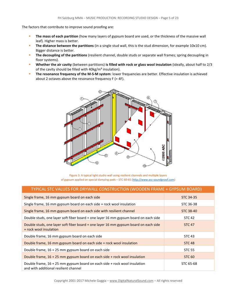
The factors that contribute to improve sound proofing are:
The mass of each partition (how many layers of gypsum board are used, or the thickness of the massive wall leaf). Higher mass is better.
The distance between the partitions (in a single stud wall, this is the stud dimension, for example 10x10 cm). Bigger distance is better.
The decoupling of the partitions (resilient channel, double studs or separate wall frames; spring decoupling in floor systems).
Whether the air cavity (between partitions) is filled with rock or glass wool insulation (ideally, about half to 2/3 of the cavity should be filled with 40kg/m³ insulation).
The resonance frequency of the M-S-M system: lower frequencies are better. Effective insulation is achieved about 2 octaves above the resonance frequency F (= 4F).
Figure 3: A typical light studio wall using resilient channels and multiple layers
of gypsum applied on special damping pads – STC 60-65 (http://www.asc-soundproof.com)
TYPICAL STC VALUES FOR DRYWALL CONSTRUCTION (WOODEN FRAME + GYPSUM BOARD)
Single frame, 16 mm gypsum board on each side STC 34-35
Single frame, 16 mm gypsum board on each side + rock wool insulation STC 36-38
Single frame, 16 mm gypsum board on each side with resilient channel STC 38-40
Double studs, one layer soft fiber board + one layer 16 mm gypsum board on each side STC 42
Double studs, one layer soft fiber board + one layer 16 mm gypsum board on each side + rock wool insulation
STC 47
Double frame, 16 mm gypsum board on each side STC 43
Double frame, 16 mm gypsum board on each side + rock wool insulation STC 48
Double frame, 16 + 25 mm gypsum board on each side STC 55
Double frame, 16 + 25 mm gypsum board on each side + rock wool insulation STC 60
Double frame, 16 + 25 mm gypsum board on each side + rock wool insulation and with additional resilient channel
STC 65-68

FH Salzburg MMA – MUSIC PRODUCTION: RECORDING STUDIO DESIGN – Page 6 of 23
Copyright 2001-2017 Michele Gaggia – www.DigitalNaturalSound.com – All rights reserved
2.3 ROOM WITHIN A ROOM CONSTRUCTION
To achieve the best sound insulation possible, commercial studio facilities are often built using the room within a room
principle: the outer shell is made from massive concrete or masonry walls and floors, taking care of most of the sound
containment and isolation from the outside world. The inner studio spaces are constructed as floating rooms with their own
supporting concrete floors, decoupled from the outer shell using elastic pads or springs. For the inner walls and ceilings
lighter materials can be used (wood or metal framing with gypsum and/or plywood panels). Great care is taken in avoiding
sound transmission at the boundaries between floors, walls and roofs, and in the installation of electrical and HVAC systems.
2.4 COMPARISON BETWEEN DIFFERENT WALL CONSTRUCTIONS
To better understand how is the acoustic performance of a M-S-M system compared to a massive wall construction, we will
compare a few wall partition types using Insul, a software designed by Marshall Day Acoustics Ltd to accurately simulate the
acoustic performance of different types of single and multi-leaf partitions.
Figure 4: Example of studio facility using room-in-room construction for every room
(from top: control room, vocal booth, live room) – DNS Studios, 2012

FH Salzburg MMA – MUSIC PRODUCTION: RECORDING STUDIO DESIGN – Page 7 of 23
Copyright 2001-2017 Michele Gaggia – www.DigitalNaturalSound.com – All rights reserved
EXAMPLE A (MASSIVE, RW 43)
This is a massive single partition wall, made of 6 layers of 12.5 mm gypsum board and supported by metal studs framing
(not shown).
This wall has a rating of Rw 43. This does not sound like much, however notice how the Sound Reduction Index graph has a
gentle slope of only 6 dB per octave (= only 6 dB insulation loss for each lower octave). The insulation provided at 63 Hz is
still 27 dB.
The insulation loss of about 10 dB at 2.7 kHz is caused by the gypsum board own “critical frequency”. Using gypsum boards
of different thickness (for example 12.5 and 15 mm) would minimize this problem.
Figure 5: A massive single partition wall, made of 6 layers of 12.5 mm gypsum board and supported by metal studs framing (not shown).
FH Salzburg MMA – MUSIC PRODUCTION: RECORDING STUDIO DESIGN – Page 8 of 23
Copyright 2001-2017 Michele Gaggia – www.DigitalNaturalSound.com – All rights reserved
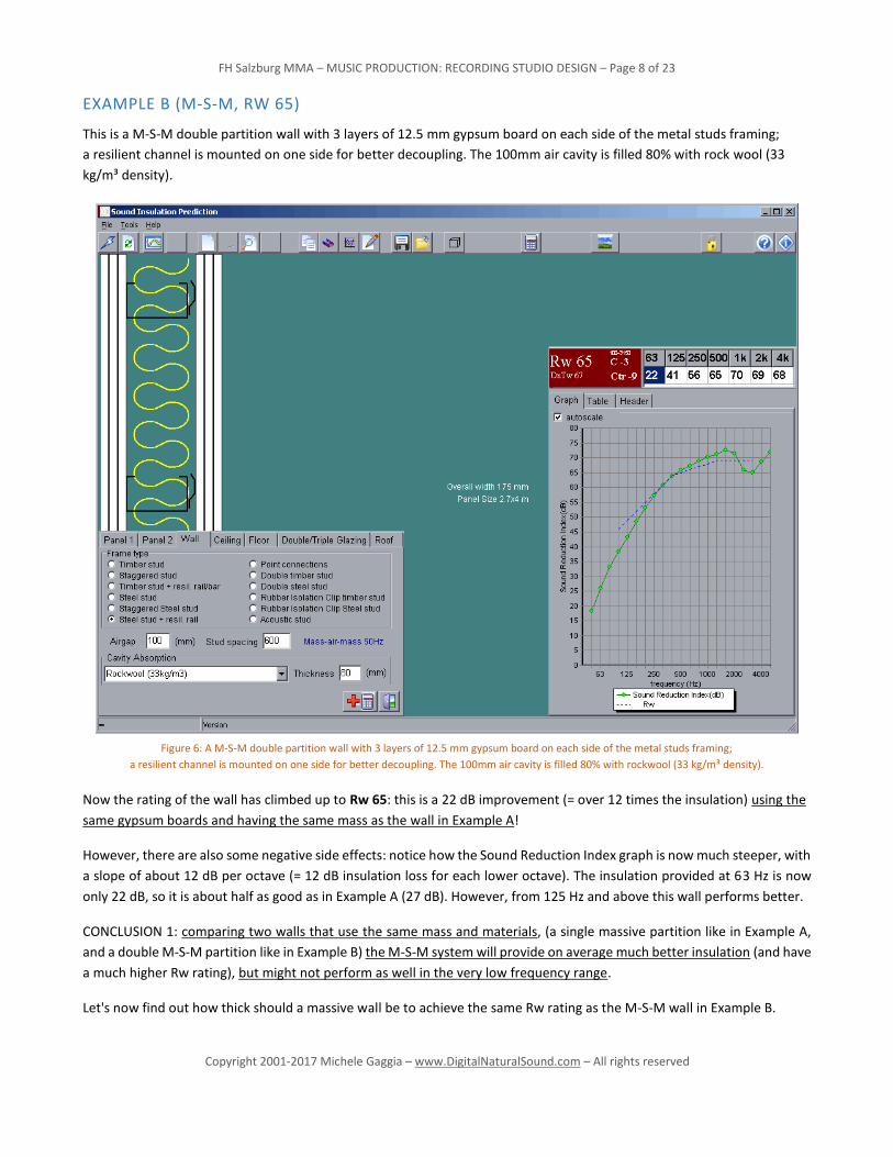
EXAMPLE B (M-S-M, RW 65)
This is a M-S-M double partition wall with 3 layers of 12.5 mm gypsum board on each side of the metal studs framing;
a resilient channel is mounted on one side for better decoupling. The 100mm air cavity is filled 80% with rock wool (33
kg/m³ density).
Now the rating of the wall has climbed up to Rw 65: this is a 22 dB improvement (= over 12 times the insulation) using the
same gypsum boards and having the same mass as the wall in Example A!
However, there are also some negative side effects: notice how the Sound Reduction Index graph is now much steeper, with
a slope of about 12 dB per octave (= 12 dB insulation loss for each lower octave). The insulation provided at 63 Hz is now
only 22 dB, so it is about half as good as in Example A (27 dB). However, from 125 Hz and above this wall performs better.
CONCLUSION 1: comparing two walls that use the same mass and materials, (a single massive partition like in Example A,
and a double M-S-M partition like in Example B) the M-S-M system will provide on average much better insulation (and have
a much higher Rw rating), but might not perform as well in the very low frequency range.
Let's now find out how thick should a massive wall be to achieve the same Rw rating as the M-S-M wall in Example B.
Figure 6: A M-S-M double partition wall with 3 layers of 12.5 mm gypsum board on each side of the metal studs framing;
a resilient channel is mounted on one side for better decoupling. The 100mm air cavity is filled 80% with rockwool (33 kg/m³ density).

FH Salzburg MMA – MUSIC PRODUCTION: RECORDING STUDIO DESIGN – Page 9 of 23
Copyright 2001-2017 Michele Gaggia – www.DigitalNaturalSound.com – All rights reserved
EXAMPLE C (MASSIVE, RW 65)
This is a massive concrete wall, 300mm thick, plastered on both sides.
This wall has the same Rw 65 rating as the M-S-M wall in Example B; to achieve this it must be over 12 times heavier (702
kg /m² vs 57 kg /m²) and much thicker as well (300 mm vs 175 mm). Obviously, it would be also much more expensive to
build.
However, its performance in the low frequency range is much better: again, the Sound Reduction Index graph shows a slope
of only 6 dB per octave. At 63 Hz this wall still provides 43 dB insulation, in other words 21 dB more (= about 11 times more)
than the M-S-M wall with the same rating.
CONCLUSION 2: comparing two walls with the same Rw rating (a heavier single massive partition as in Example C, and a
lighter double M-S-M partition as in Example B), the massive wall will provide much better insulation in the low frequency
range.
Figure 7: A massive concrete wall, 300mm thick, plastered on both sides.

FH Salzburg MMA – MUSIC PRODUCTION: RECORDING STUDIO DESIGN – Page 10 of 23
Copyright 2001-2017 Michele Gaggia – www.DigitalNaturalSound.com – All rights reserved
2.5 NC CURVES
Figure 8:NC (Noise Criterion) curves
The goal for a professional studio facility should be a NC (Noise Criterion curve) value of 15 or less. NC curves weights middle-
high frequencies more than lower ones, where we have reduced hearing sensitivity.
After a measurement of the environment noise in the area where the studio must be built, it is possible to compare that
curve with the target NC curve: the difference is the amount of insulation required by the studio construction to achieve
noise levels.
These NC values should not be compromised by a loud operating HVAC (Heating, Ventilation & Air Conditioning) system:
this must be planned accordingly and operate at very silent levels under the target NC curve.
3. ACOUSTIC CONTROL
A lot of different factors can influence the acoustic properties and can contribute to the sound of a room:
Room size: affects both the low frequency response and the room cutoff frequency, as well as rev. time. Room shape and proportions (room dimensions, parallel or non-parallel surfaces): affect the resonance modes
and the frequency response, and the diffusion of the reverberation. Reverberation time: depends on the room size as well as the absorption coefficients of the materials used for all
surfaces. Frequency response: depends from size, shape and absorption coefficients. Doors and windows construction and placement. Acoustic Modules (wide-band absorbers, bass traps, diffusers, resonators, etc.). Furniture, placement of equipment (mixer, effect racks, etc.), instruments, etc. In a control room, the placement of loudspeakers (flush mounted main monitors, midfield and nearfield monitors).

FH Salzburg MMA – MUSIC PRODUCTION: RECORDING STUDIO DESIGN – Page 11 of 23
Copyright 2001-2017 Michele Gaggia – www.DigitalNaturalSound.com – All rights reserved
3.1 ACOUSTIC REQUIREMENTS
The sound requirements for control rooms can be very different from those of recording rooms.
Control Rooms should be as neutral as possible, in other words they should add no coloration whatsoever to the sound
coming out of the monitor loudspeakers (in an ideal case, you should not hear the room coloring at all).
A more neutral encoding of the sound during mixing/mastering ensures higher chances that the decoding on any given
system will be closer to the original. Any coloration added during mixing/mastering can potentially be made worse due to
additional colorations during playback on other systems and cause extreme irregular frequency responses.
Recording Rooms on the other hand not only can, but should have character. Depending on the kind of instruments and
musical style, the requirements might vary. Recording rooms do not need sound neutral like control rooms, nor should they
always be symmetrical.
Usually larger studio facilities have a selection of different acoustic spaces with different characteristics:
live rooms, with longer reverberation, for instrumental recording dead rooms, with little or no reverberation, for vocal or speech recording rooms with variable acoustics (using moving or rotating panels, curtains, mobile walls, etc. etc.)
Generally, vocal and speech recording rooms should usually offer a relatively dry and uncolored acoustic, to achieve maxi-
mum clarity. This can be both provided by a very absorptive small room, or in a neutral sounding larger room.
The acoustic of instrumental recording rooms might vary between relatively dry (0.5 – 0.8 sec reverb) to quite reverberant
(1.2 – 2.5 sec) depending on the musical style.
Sometimes classical music instrument and choir require longer reverberation times that can only be achieved in concert
halls or churches.
Isolation Booths should be as dead as possible to minimize transmission of sound across the rooms they connect. Here the
sound and frequency response of the room is irrelevant.
Machine Rooms should also be as dead as possible, to avoid that equipment noise resonates or is amplified and in extreme
case leaks in the adjacent rooms.

FH Salzburg MMA – MUSIC PRODUCTION: RECORDING STUDIO DESIGN – Page 12 of 23
Copyright 2001-2017 Michele Gaggia – www.DigitalNaturalSound.com – All rights reserved
3.2 ROOM PARAMETERS
3.2.1 ROOM SHAPE AND PROPORTIONS – EIGENMODI
The room shape and proportions affect the pattern of the Eigenmodi (the room own resonance modes), and the amount of
“diffusion” (density of the reverberation).
The room modes are classified in:
Axial Modes occurring between opposite parallel surfaces, therefore along the 3 main axis of the room: the dominant factor
Tangential Modes occurring among 4 surfaces, avoiding 2 that are parallel: can still be significant in rooms with hard/stiff surfaces
Oblique Modes occurring among all surfaces: are rarely significant
An easy way to calculate the Axial Modes of a room is:
f1 = c
2 x L
f1 = frequency of the 1st axial mode c = speed of sound and L = dimension of the room considered
The next axial modes of that dimensions are simply:
f2 = 2x f1 f3 = 3x f3 …..
The Eigenmodi should be spaced as evenly as possible. Therefore, room proportions where one dimension is a multiple of
the other (like a room with 10 x 5 x 2,5 m size), or with same dimensions for length, width and height (like a room with 5 x
5 x 5 m size), must be absolutely avoided: this would generate extreme strong resonances of certain frequencies that are
supported by all three room dimensions (in example 1: waves resonating at the 2,5 dimension fit also the 5 and 10 m di-
mensions).
There are several studies about optimal room proportions, for example:
L. W. Sepmeyer (1965): 1 : 1.14 : 1.39 1 : 1.28 : 1.54 1 : 1.60 : 2.33
M. M. Louden (1971): 1 : 1.40 : 1.90 1 : 1.30 : 1.90 1 : 1.50 : 2.10
Check this post by Eric Desart (designer of Galaxy Studios in Belgium and moderator of the Studiotip Acoustic Forum)
about the Acceptable Room Ratios for more information: http://forum.studiotips.com/viewtopic.php?p=5570

FH Salzburg MMA – MUSIC PRODUCTION: RECORDING STUDIO DESIGN – Page 13 of 23
Copyright 2001-2017 Michele Gaggia – www.DigitalNaturalSound.com – All rights reserved
EXAMPLE OF ROOM MODE CALCULATION
Here an example of room mode plot for a control room with dimensions 6.7 x 5.3 x 3.5 m:
The highest lines in the plot are axial modes (strongest), the mid ones are tangential, and the lowest are oblique modes
(weakest). The plot shows a rather even distribution, with good spacing and no axial or tangential modes overlapping. Fine
tuning of the modal distribution is possible by adjusting the room dimensions in centimeter steps.
Figure 9: Example of room mode plot for a control room with dimensions 6.7 x 5.3 x 3.5 m,
using the room mode calculator at http://amroc.andymel.eu/

FH Salzburg MMA – MUSIC PRODUCTION: RECORDING STUDIO DESIGN – Page 14 of 23
Copyright 2001-2017 Michele Gaggia – www.DigitalNaturalSound.com – All rights reserved
3.2.2 BOLT AREA
Richard H. Bolt (1911-2002) found an area of cumulative good room ratios, including his own and those suggested by L. W.
Sepmeyer, M. M. Louden. The room shown in Fig. 9 (dimensions: 670 x 530 x 350 cm) fits quite in the middle of the Bolt
Area.
Of course, when the room layout is not based on parallel surfaces, like in modern RFZ control rooms, it is not easy to predict
the exact behavior of room resonances. A good approximation can be achieved using the average between the bigger and
smaller dimension for the calculations. For example, if a Control room is 6 m wide in the back and 4,6 m wide in the front,
the average would be ( 6 + 4,6) : 2 = 5,3 m.
Only very expensive acoustic design software can currently give an accurate prediction of the Eigenmodi is rooms with
complex geometry.
Figure 10: Graph showing how the chosen room proportions fit quite in the middle of the Bolt Area:

FH Salzburg MMA – MUSIC PRODUCTION: RECORDING STUDIO DESIGN – Page 15 of 23
Copyright 2001-2017 Michele Gaggia – www.DigitalNaturalSound.com – All rights reserved
3.2.3 ROOM SIZE AND REVERBERATION TIME
Room size affects the lowest frequencies that can be played back with support from the room own resonance modes
(Eigenmodi), as well as the reverberation time.
In larger rooms, the natural resonating modes start from a lower frequency; therefore, the Eigenmodi are less spaced apart
(= denser) in the critical range between 20 and 200 Hz compared to small rooms. As there are less resonance peaks and
gaps, a more even frequency response is easily achieved, and besides the rev. time can be relatively constant across the
sound spectrum.
Reverberation time is generally longer in a larger room, as it takes longer time for sound waves to travel from one surface
to another, and more time for the sound energy to be dampened/absorbed by these surfaces. The effective rev. time de-
pends on both size and the absorption coefficient of the materials used.
A Control Room should ideally not be smaller than about 100 m³ (like in the example above, 6.5 x 5.3 x 3.5 m = 124 m³), if
frequencies down to 25 Hz must be played back with natural mode reinforcement. Unfortunately, many control rooms do
not even meet this basic requirement.
Recording Room sizes can vary, depending from what should be recorded: a booth for dry vocal or drum recording could be
a few m³ size (for example, 3,5 x 2 x 2,5 = 17,5 m³), while a room for ensemble recording should be at least 150-200 m³ in
size (for example, 9 x 5,5 x 4 = 198 m³), to provide adequate diffusion and a rev. time of about 0,5 – 0,7 sec.
3.3 CONTROL ROOMS
3.3.1 BASIC REQUIREMENTS
In modern design of Control Rooms, the tendency is towards a symmetrical layout, but without parallel surfaces: slanted
walls contribute to diffusion (denser reverberation) and avoid slap-back and flutter-echo effects, as the sound waves cannot
bounce back and forth between the two parallel surfaces. For the same reason, the ceiling of a Control Room is not parallel
to the floor, but usually is lower near the front wall, and higher towards the back wall.
Slap-back and flutter-echo are undesired phenomena which would greatly compromise the acoustic of the room, so they
should be avoided in any case.
SIZE
The standard size of a modern Control Room is about 7 m length by about 4 to 6 m width (4 m for the front wall with flush
mounted speakers, and 6 m for the back wall with diffusors). The height varies between 2.5 (front) and 3.5 m (back). The
effective height of the structure is often a higher value, if large amounts of wide-band absorbers are to be fitted in the
ceiling.
It is important that the back wall is about 3 – 3.5 m away from the mixing position, so that the reflections from that wall
(usually fitted with diffusers) arrives about 18-22 ms after the direct sound from the main speakers. This time gap is im-
portant to avoid comb-filtering and smearing of the stereo image. Larger time gaps are undesired, as it would be perceived
as a distinct echo reflection.

FH Salzburg MMA – MUSIC PRODUCTION: RECORDING STUDIO DESIGN – Page 16 of 23
Copyright 2001-2017 Michele Gaggia – www.DigitalNaturalSound.com – All rights reserved
REVERB TIME
In a control room the reverb time should be as short as possible, and in any case shorter as the reverb time of the recording
rooms; otherwise it would mask the sound of the acoustic spaces being recorded.
The standard reverberation decay time RT60 (the time the sound energy of the reverb takes to drop 60dB from the direct
sound emission) for a modern Control Room is between 300 ms (LF) and 200 ms (HF). Larger Control Rooms (over 60 m²
area) might have higher RT60, but it is important that the level of the reverberation remains as low as possible.
This requires large amount of wide-band absorbing elements, usually placed on the ceiling (rock, glass or wood fiber wool,
between 10 and 50 cm thick depending on the lowest target frequency to be absorbed, enclosed in supporting wooden or
metal frames). If some surfaces are using materials that absorb only in the mid and high range (like carpets or curtains),
special low frequency absorption elements must be used to compensate and achieve a linear response (bass traps, Helm-
holtz resonators).
A completely dry room is not desirable, as it causes listening fatigue: the ideal goal would be to receive dry, coherent sound
from the monitor loudspeakers within the first 20 ms, undisturbed by any early reflection, followed by a diffused room
reverb with about 200-300 ms decay time.
3.3.2 CONTROL ROOM LAYOUTS
The most common design types to achieve this goal are LEDE (Live End, Dead End), RFZ (Reflection Free Zone), Non-Environ-
ment and ESS (Early Sound Scattering)
LEDE
Live End / Dead End Control Rooms are built on the following principles: the speaker front walls and ceiling (the Dead End)
are very absorptive, to eliminate secondary paths from the monitors to the listening position; the back wall (the Live End) is
rather reflective and can include a set of diffusors to provide pleasant reflections back to the listening position. These dif-
fused reflections do not color the sound, as they come after about 20 ms delay and are reduced in intensity; if properly
directed they can even improve stereo imaging. The Live End removes the unpleasant feeling one would have working in a
completely dead room, while the Dead End guarantees precise monitoring.
Figure 11: A typical “old style” LEDE room (The London 12)

FH Salzburg MMA – MUSIC PRODUCTION: RECORDING STUDIO DESIGN – Page 17 of 23
Copyright 2001-2017 Michele Gaggia – www.DigitalNaturalSound.com – All rights reserved
RFZ
Reflection Free Zone Control Rooms are an improvement over LEDE, where a special room geometry is used instead of an
absorptive front wall and ceiling to avoid secondary paths and early reflections from the speakers.
The main monitors are always soffit or wall mounted in this type of room; the front walls and ceiling are constructed at
specific angles that disperse the sound in the direction of the back wall. This guarantees precise stereo imaging and clear,
uncolored sound.
The back wall usually has a large array of Quadratic Residue Diffusors (QRDs, like from the company RPG), which provide
pleasant diffused reflections without interfering with the direct sound from the monitors. Like with the LEDE design, the
optimal distance from the mixing position to the back wall should be about 3,4 m to get the diffused reflections after a time
delay of about 20 ms:
(2 x 3,4 m): 340 m/s = 0,020 s = 20 ms
Values between 18 and 22 ms are optimal. A shorter time delay may cause comb filtering, while a longer delay might be
perceived as a slap-back echo, neither of which is desirable.
Because the parquet wooden floor is also quite reflective, in RFZ rooms it is necessary to have an extremely absorptive
ceiling (wide band, full range absorption + bass traps) in order to keep reverberation time under the desired limit of about
0.3 sec (for a 35-45 m² room) and avoid floor/ceiling flutter echo.
Figure 12: A large RFZ control room (The Mushroom, Austria) with flush mounted main monitors (ADAM S7 mk I),
absorptive ceiling, wooden floor, and rear diffusor array

FH Salzburg MMA – MUSIC PRODUCTION: RECORDING STUDIO DESIGN – Page 18 of 23
Copyright 2001-2017 Michele Gaggia – www.DigitalNaturalSound.com – All rights reserved
NON-ENVIRONMENT
Non-Environment Control Rooms are basically hemi-anechoic chambers, where all surfaces except the speaker front wall
and the floor are extremely absorptive. The speaker front wall is constructed like in a RFZ design and disperses the reflections
towards the absorptive back wall and ceiling.
In the Non-Environment room, there are no QRD diffusors on the back wall: instead, a large wide-band / bass absorber is
built using hanging elements. Therefore, there is no wash of diffused reflections after 20ms, like in the LEDE or RFZ designs.
The ceiling is also built as a large wide-band / bass absorber (like in the RFZ design). The room does not sound unpleasantly
dead when speaking, thanks to the reflective wooden floor and front speaker wall, which is often built out of stone slabs.
Non-Environment rooms can sound incredibly crispy and accurate: it is possible to perceive details that can otherwise be
heard only over headphones. However, their sound is unlike any other typical listening environment, therefore they do not
translate very well to standard listening environments. Also, because of the high levels of absorption, the monitoring system
must supply very high power to provide the desired SPL levels.
As in Non-Environment rooms the natural room Eigenmodi die away very quickly, they do not influence much the frequency
response of the room. It is therefore possible to build Control Rooms that are smaller than 100 m³ and still offer a quite
linear playback. It is also possible to have the back wall closer than 3,4 m, as it is completely absorptive.
Figure 13: A typical Non-Environment control room (Lamiña Production Studios, Spain)
showing stone front speaker wall, wooden floor, absorptive ceiling, side and back walls

FH Salzburg MMA – MUSIC PRODUCTION: RECORDING STUDIO DESIGN – Page 19 of 23
Copyright 2001-2017 Michele Gaggia – www.DigitalNaturalSound.com – All rights reserved
ESS
Early Sound Scattering is in principle similar to LEDE with one important difference: instead of the absorbers used in the
LEDE design, a large number of diffusors are installed not only in the back wall, but also in the front wall and ceiling. The
early reflections are not completely eliminated, but have a smoother, diffused pattern that causes less comb filtering (and
therefore less coloration).
Another argument to support this type of control room: the diffused reflections help masking the unavoidable reflections
from the mixing desk.
Figure 14: Early Sound Scattering control room (Graceland Studios) with the typical diffusors installed on the front wall and ceiling

FH Salzburg MMA – MUSIC PRODUCTION: RECORDING STUDIO DESIGN – Page 20 of 23
Copyright 2001-2017 Michele Gaggia – www.DigitalNaturalSound.com – All rights reserved
4. ABSORPTION COEFFICIENTS OF STANDARD BUILDING MATERIALS AND FINISHES
NRC (NOISE REDUCTION COEFFICIENT)
NRC is a sound absorption rating. It measures a percentage of how much sound will not be reflected from where it came.
Based on a range from .05 to 1.0, where a NRC of 1.0 means that all the sound energy that hits that product passes through
it and does not bounce back to its source. A NRC of .60 would reflect 40% of the sound back to the source, and let 60% of
the noise pass through it.
4.1 FLOOR MATERIALS
MATERIALS 125 Hz 250 Hz 500 Hz 1000 Hz 2000 Hz 4000 HZ
concrete or tile .01 .01 .15 .02 .02 .02
linoleum/vinyl tile on concrete .02 .03 .03 .03 .03 .02
wood on joists .15 .11 .10 .07 .06 .07
parquet on concrete .04 .04 .07 .06 .06 .07
carpet on concrete .02 .06 .14 .37 .60 .65
carpet on foam .08 .24 .57 .69 .71 .73
4.2 SEATING MATERIALS
MATERIALS 125 Hz 250 Hz 500 Hz 1000 Hz 2000 Hz 4000 HZ
fully occupied - fabric upholstered .60 .74 .88 .96 .93 .85
occupied wooden pews .57 .61 .75 .86 .91 .86
empty - fabric upholstered .49 .66 .80 .88 .82 .70
empty metal/wood seats .15 .19 .22 .39 .38 .30

FH Salzburg MMA – MUSIC PRODUCTION: RECORDING STUDIO DESIGN – Page 21 of 23
Copyright 2001-2017 Michele Gaggia – www.DigitalNaturalSound.com – All rights reserved
4.3 WALL MATERIALS
MATERIALS 125 Hz 250 Hz 500 Hz 1000 Hz 2000 Hz 4000 HZ
Brick: unglazed .03 .03 .03 .04 .05 .07
Brick: unglazed & painted .01 .01 .02 .02 .02 .03
Concrete block - coarse .36 .44 .31 .29 .39 .25
Concrete block - painted 0.10 .05 .06 .07 .09 .08
Curtain: 10 oz/sq yd fabric .03 .04 .11 .17 .24 .35
Curtain: 14 oz/sq yd .07 .31 .49 .75 .70 .60
Curtain: 18 oz/sq yd .14 .35 .55 .72 .70 .65
Fiberglass: 2" 703 no airspace .22 .82 .99 .99 .99 .99
Fiberglass: spray 5" .05 .15 .45 .70 .80 .80
Fiberglass: spray 1" .16 .45 .70 .90 .90 .85
Fiberglass: 2" rolls .17 .55 .80 .90 .85 .80
Foam: Sonex 2" .060 .25 .56 .81 .90 .91
Foam: SDG 3" .24 .58 .67 .91 .96 .99
Foam: SDG 4" .33 .90 .84 .99 .98 .99
Foam: polyur. 1" .13 .22 .68 1.0 .92 .97
Foam: polyur. 1/2" .09 .11 .22 .60 .88 .94
Glass: 1/4 plate large .18 .06 .04 .03 .02 .02
Glass: window .35 .25 .18 .12 .07 .04
Plaster: smooth on tile/brick .013 .015 .02 .03 .04 .05
Plaster: rough on lath .02 .03 .04 .05 .04 .03
Marble/Tile .01 .01 .01 .01 .02 .02
Sheetrock 1/2" 16"o.c. .29 .10 .05 .04 .07 .09
Wood: 3/8" plywood panel .28 .22 .17 .09 .10 .11

FH Salzburg MMA – MUSIC PRODUCTION: RECORDING STUDIO DESIGN – Page 22 of 23
Copyright 2001-2017 Michele Gaggia – www.DigitalNaturalSound.com – All rights reserved
4.4 CEILING MATERIALS
MATERIALS 125 Hz 250 Hz 500 Hz 1000 Hz 2000 Hz 4000 HZ
Acoustic Tiles .05 .22 .52 .56 .45 .32
Acoustic Ceiling Tiles .70 .66 .72 .92 .88 .75
Fiberglass: 2" 703 no airspace .22 .82 .99 .99 .99 .99
Fiberglass: spray 5" .05 .15 .45 .70 .80 .80
Fiberglass: spray 1" .16 .45 .70 .90 .90 .85
Fiberglass: 2" rolls .17 .55 .80 .90 .85 .80
wood .15 .11 .10 .07 .06 .07
Foam: Sonex 2" .060 .25 .56 .81 .90 .91
Foam: SDG 3" .24 .58 .67 .91 .96 .99
Foam: SDG 4" .33 .90 .84 .99 .98 .99
Foam: polyur. 1" .13 .22 .68 1.0 .92 .97
Foam: polyur. 1/2" .09 .11 .22 .60 .88 .94
Plaster: smooth on tile/brick .013 .015 .02 .03 .04 .05
Plaster: rough on lath .02 .03 .04 .05 .04 .03
Sheetrock 1/2" 16"o.c. .29 .10 .05 .04 .07 .09
Wood: 3/8" plywood panel .28 .22 .17 .09 .10 .11
4.5 MISCELLANEOUS MATERIALS
MATERIALS 125 Hz 250 Hz 500 Hz 1000 Hz 2000 Hz 4000 HZ
Air: sabins/100 cu. ft. 0.90 2.3 7.2
Water 0.008 0.008 0.013 0.015 0.020 0.025
People - adults 0.25 0.35 0.42 0.46 0.5 0.5

FH Salzburg MMA – MUSIC PRODUCTION: RECORDING STUDIO DESIGN – Page 23 of 23
Copyright 2001-2017 Michele Gaggia – www.DigitalNaturalSound.com – All rights reserved
RECOMMENDED LITERATURE
EVEREST, F. ALTON: Master Handbook of Acoustics – McGrav Hill (ISBN 0-07-136097-2) SHEA, Mike: Small Budget Recording Studio – McGrav Hill (ISBN 0-07-138700-5) GERVAIS, Rod: Home Recording Studio: Build It Like the Pros – Course Technology (ISBN-13: 978-1435457171)
RECOMMENDED INTERNET LINKS Acoustic Treatment for Home Studios – Peter Elsea
http://arts.ucsc.edu/ems/music/tech_background/TE-14/teces_14.html Acoustic Forum StudioTips
http://forum.studiotips.com
ACOUSTIC CALCULATORS Eigenmodi Calculator
http://amroc.andymel.eu Room sizes compliance with international standards and recommendations
http://www.acoustic.ua/forms/rr.en.html Eigenmodi Calculator – Hunecke
http://www.hunecke.de/german/rechenservice/raumeigenmoden.html Reverb Time Calculator – Hunecke
http://www.hunecke.de/german/rechenservice/raumakustik.html
WEBSITE
http://www.digitalnaturalsound.com/fh-multimediaart/music-production.html
www.digitalnaturalsound.com or www.dns-studios.com > FH | MultiMediaArt > Music Production