record plus molded case circuit breakers - ge...
TRANSCRIPT
imagination at work
GEElectrical Distribution
Record PlusMolded Case Circuit Breakers

1
Record PlusAt a Glance
Molded Case Circuit Breaker
Characteristics
FC 100 FB 100 FE 250 FG 600(Max) Frame Rating 100A 100A 250A 600A
Trip Unit Thermal-Magnetic Thermal - Magentic Electronic ElectronicCurrent Range 15A - 100A 15A - 100A 20A - 250A 100A - 600A
Frame FCS FCV FCN FCH FCL FBV FBN FBH FBL FEN FEH FEL FGN FGH FGL FGPPoles 2, 3 1 2 3 1 2 3 1 2 3 1 2 3 2, 3 2, 3
Interruption Ratings
UL / CSA Rating (kA
RMS) (50 / 60 Hz AC)
240 V 42 65 150 200 200 35 65 65 150 100 200 100 200 150 200 200 150 200 200 200277V - - - - - 35 - 65 - 100 - 150 - - - - - - - -480 V 25 35 65 100 150 - 35 - 65 - 100 - 150 65 100 150 65 100 150 200347V - - - - - 22 - 25 - 35 - 42 - - - - - - - -
600/347 V 18 22 25 35 42 - 22 - 25 - 35 - 42 - - - - - - -600 V - - - - - - - - - - - - - - - - 25 35 42 65
UL / CSA Rating (kA @
VDC)
250V (2p) 22 25 30 42 65- - - - - -
500V (3p) 30 35 42 65 80
IEC 947-2 Rating (50/60
Hz AC)
220-240 V 36 50 85 100 200
- - -
85 100 200 -400 - 415 V 22 30 50 80 150 50 80 150 -
500V 14 18 22 36 50 - - - -690 V - - - - - 10 22 40 -
IEC 947-2 (kA @ VDC)
250 (2p) 22 25 30 42 65- - - - - -
500 (3p) 30 35 42 65 80
Additional Markings /
Ratings
cUL Yes Yes Yes Yes Yes Yes YesHACR Yes Yes Yes Yes Yes Yes Yes
Reverse Feed Yes Yes Yes Yes Yes Yes Yes NoNaval Yes Yes Yes Yes Yes Yes NoHID Yes (15-50A) Yes (15-50A) Yes (15-50A) No No
Current Limiting Yes Yes Yes Yes Yes Yes Yes
GE Equipment Availability
A-Series (Main) - - - AD, AE, AQA-Series (Branch) - AD - -
Spectra (Main) - - - SBO / SPOSpectra (Branch) SBO / SPO SBO / SPO SBO / SPO SBO / SPO
EnvelopeDimensions
H (in / mm) 6.4 / 162.6 6.45 / 163.8 6.70 / 170.1 10.31 / 262.0
W (in / mm) 3.0 / 76.21-Pole 2- Pole 3- Pole
4.11 / 104.4 5.46 / 138.71.36 / 34.5 2.74 / 69.6 4.11 / 104.4
D (in / mm) 3.2 / 81.3 3.28 / 83.3 3.28 / 83.3 3.28 / 83.3 3.52 / 89.5 4.53 / 115.0Weight (lb) 2.5 1.1 2.6 3.3 4.5 22
Molded Case SwitchCharacteristics FC 100(Max) Frame Rating 100ATrip Unit Molded Case SwitchCurrent Range 60 or 100APoles 2, 3
Withstand Rating (kA RMS @VAC)
240 V 200480 V 150600 V 42
EnvelopeDimensions
H (in / mm) 6.4 / 162.6W (in / mm) 3.0 / 76.2D (in / mm) 3.2 / 81.3
Weight (lb) 2.5
*Molded Case Switch Withstand ratings depend upon the short circuit rating of an upstream fuse or circuit breaker. The maximum withstand rating is limited to the rating of the upstream device or the value in this table, whichever is less. The upstream device must have an instantaneous trip function or element and its rated amperage may not exceed the rated current of the switch
Series Ratings: DET-008Selectivity Ratings: DET-537

2
Product Markings
FB100• cUL US – UL 489 File E-11592• HACR, Naval, Current Limiting• HID (15-50A)• FB Breakers are NOT marked Line/Load and are suitable for Reverse Feed
FC100• cUL US – UL 489 File E-11592• IEC 947-2 and Associated EN Sections• HACR, Naval, Current Limiting• FC Breakers are NOT marked Line/Load and are suitable for Reverse Feed
FE250• cUL US – UL 489 File E-11592• HACR, Naval, Current Limiting• FE Breakers are NOT marked Line/Load and are suitable for Reverse Feed
FG600• cUL US – UL 489 File E-11592• IEC 947-2 and Associated EN Sections• HACR, Current Limiting• FGN and FGH breakers are NOT marked Line/Load and are suitable for Reverse Feed• FGL and FGP breakers are marked Line/Load and are NOT suitable for Reverse Feed
Features and Benefits
GE’s name is synonymous with a broad range of products designed to meet our customers’ changing and competitive environment. Our drive to exceed our customers’ expectations is the foundation for continual renewal of our commitment to provide innovative low voltage solutions.
Using world class design and development tools like Six Sigma, Computer Simulations and Lean Manufacturing, Record Plus is intended to meet and exceed the most stringent quality, safety and performance standards. At GE, we are proud to offer a product that will offer years of reliable and dependable protection.
Record Plus is a line of high performance protective devices that are designed to be aesthetically and technically compatible and suited for a wide range of applications. The high short circuit ratings and selective coordination capabilities of Record Plus provide a common platform solution to a wide range of commercial and industrial applications.
Advanced and PowerfulDouble rotary style contacts and features such as reverse loop current paths and advanced arcing chamber designs give Record Plus breakers exceptional current limiting performance. Advanced thermal-magnetic and electronic trip units allow Record Plus circuit breakers to respond to faults at the most downstream level, isolating outages to circuits affected by a fault. These two features can provide a combination of arc flash reduction and selectivity, thereby meeting the demands of today’s complex distribution systems. Specify Record Plus breakers where total selective coordination is required.
In addition to current limitation, the Record Plus double rotary contact structure makes these breakers capable of exceptionally high short circuit ratings. Frames 250A and below are capable of 150kAIC, while the 600A frame
3
is rated up to 200kA. Specify and use Record Plus in spot networks, downtown distribution grids or anywhere available currents are high.
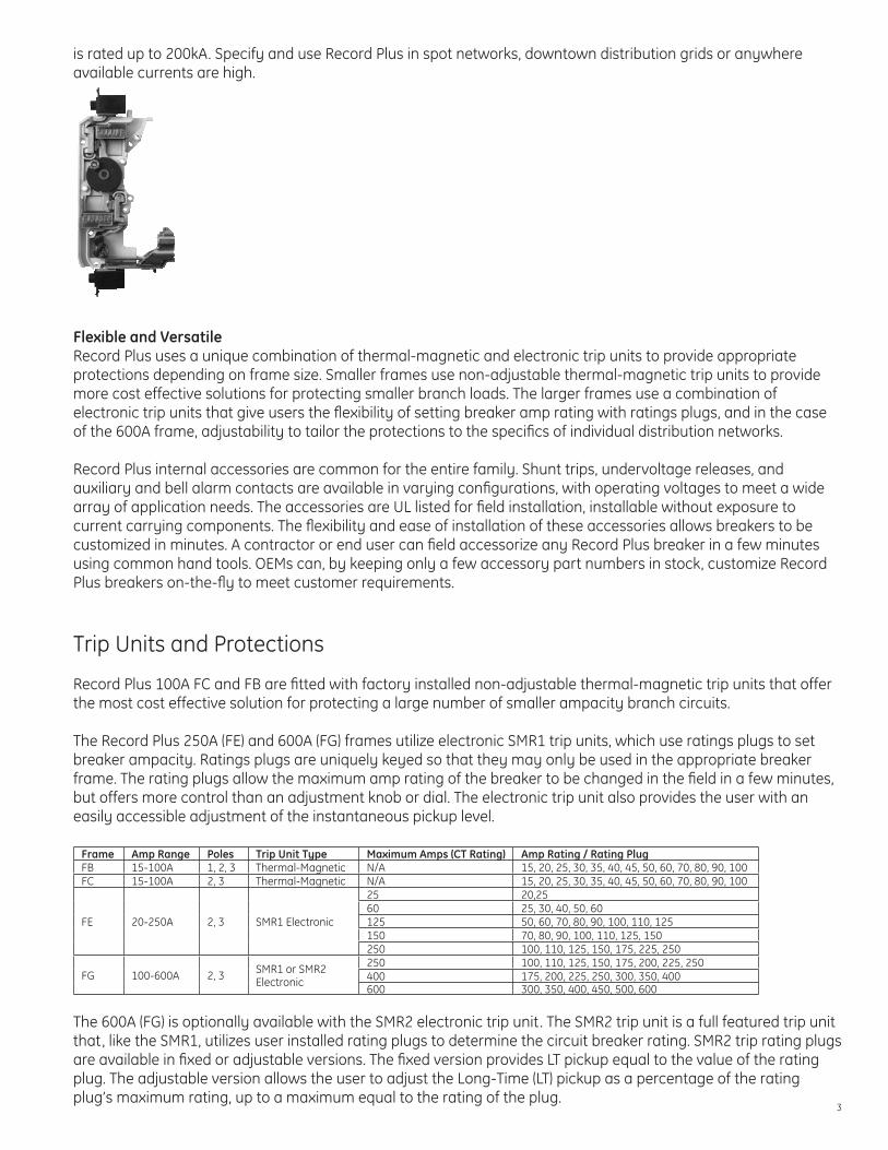
Flexible and VersatileRecord Plus uses a unique combination of thermal-magnetic and electronic trip units to provide appropriate protections depending on frame size. Smaller frames use non-adjustable thermal-magnetic trip units to provide more cost effective solutions for protecting smaller branch loads. The larger frames use a combination of electronic trip units that give users the flexibility of setting breaker amp rating with ratings plugs, and in the case of the 600A frame, adjustability to tailor the protections to the specifics of individual distribution networks.
Record Plus internal accessories are common for the entire family. Shunt trips, undervoltage releases, and auxiliary and bell alarm contacts are available in varying configurations, with operating voltages to meet a wide array of application needs. The accessories are UL listed for field installation, installable without exposure to current carrying components. The flexibility and ease of installation of these accessories allows breakers to be customized in minutes. A contractor or end user can field accessorize any Record Plus breaker in a few minutes using common hand tools. OEMs can, by keeping only a few accessory part numbers in stock, customize Record Plus breakers on-the-fly to meet customer requirements.
Trip Units and Protections
Record Plus 100A FC and FB are fitted with factory installed non-adjustable thermal-magnetic trip units that offer the most cost effective solution for protecting a large number of smaller ampacity branch circuits.
The Record Plus 250A (FE) and 600A (FG) frames utilize electronic SMR1 trip units, which use ratings plugs to set breaker ampacity. Ratings plugs are uniquely keyed so that they may only be used in the appropriate breaker frame. The rating plugs allow the maximum amp rating of the breaker to be changed in the field in a few minutes, but offers more control than an adjustment knob or dial. The electronic trip unit also provides the user with an easily accessible adjustment of the instantaneous pickup level.
Frame Amp Range Poles Trip Unit Type Maximum Amps (CT Rating) Amp Rating / Rating PlugFB 15-100A 1, 2, 3 Thermal-Magnetic N/A 15, 20, 25, 30, 35, 40, 45, 50, 60, 70, 80, 90, 100FC 15-100A 2, 3 Thermal-Magnetic N/A 15, 20, 25, 30, 35, 40, 45, 50, 60, 70, 80, 90, 100
FE 20-250A 2, 3 SMR1 Electronic
25 20,2560 25, 30, 40, 50, 60125 50, 60, 70, 80, 90, 100, 110, 125150 70, 80, 90, 100, 110, 125, 150250 100, 110, 125, 150, 175, 225, 250
FG 100-600A 2, 3 SMR1 or SMR2 Electronic
250 100, 110, 125, 150, 175, 200, 225, 250400 175, 200, 225, 250, 300, 350, 400600 300, 350, 400, 450, 500, 600
The 600A (FG) is optionally available with the SMR2 electronic trip unit. The SMR2 trip unit is a full featured trip unit that, like the SMR1, utilizes user installed rating plugs to determine the circuit breaker rating. SMR2 trip rating plugs are available in fixed or adjustable versions. The fixed version provides LT pickup equal to the value of the rating plug. The adjustable version allows the user to adjust the Long-Time (LT) pickup as a percentage of the rating plug’s maximum rating, up to a maximum equal to the rating of the plug.

4
The SMR2 trip unit features adjustable short-time (ST) pickup and delay, and adjustable instantaneous (INST) pickup. Zone Selective Interlocking (ZSI) capability is available as well. User installed expansion modules make available Adjustable Ground Fault (GF) Trip or Ground Fault Alarm, Communications, Load Shedding, Basic Metering, and Trip Mode Indication.
Frame Trip Unit Type LT ST Inst GFFE 250 SMR1 Electronic Set by Rating Plug N/A Adjustable N/A
FG 600SMR1 Electronic Set by Rating Plug N/A Adjustable N/A
SMR2 ElectronicSet by Rating Plug Fixed Fixed AdjustableAdjustable - Max. Set by Rating Plug Adjustable PU and Delay Adjustable Adjustable PU and Delay
0.01
0.10
1.00
10.00
100.00
1000.00
10 100 1,000 10,000 100,000 1,000,000
Amperes
Long-Time Delay
Short-Time Delay
Long-Time Pickup
Short-Time Pickup
Inst. Pickup
I2t “OFF”
I2t “ON”
Long-time ProtectionLong time protection is fixed for SMR1 equipped FE250 and FG600 breakers; the long-time pickup value will be the ampacity of the rating plug selected. SMR2 equipped FG600 breakers can be fitted with either of two types of rating plugs. A fixed rating plug will provide a long-time pickup value equal to that of the rating plug. An adjustable rating plug will enable the long-time pickup and delay to be user adjusted.
5
Long-time PickupFor each SMR2 adjustable rating plug, there are sixteen possible rating plug positions, labeled in Amps, up to a maximum setting equal to the rating of the plug. This setting establishes the current setting of the breaker, which is the maximum current the breaker will carry continuously without tripping.
Long-time DelayLong time delay varies the time it will take the breaker to trip under a sustained overload condition. This setting permits the breaker to ride through momentary predictable overloads (such as motor starting inrush current) without tripping. Each adjustable rating plug allows adjustment of the delay. Settings range from 1.25 to 10 seconds (at 7.2 times the rating plug ampacity).
Long-time Delay with Motor ProtectionAlso included in the long-time delay is a motor protection mode. When set to motor protection mode, a phase loss protection is initiated that will trip the breaker when the difference in current between one phase current and the other phases exceeds 80% for more than two seconds.
Long-time Load IndicatorThe trip unit is equipped with a LT load indicator device that operates by means of an LED indicator located on the trip unit front face. If the load reaches 60% of the set LT pickup value, a green LED will start to blink. When the load reaches 75% or above, the LED will remain on.
Short-time ProtectionAdjustable short time protection is standard on SMR2 equipped FG600 breakers. FE250 or FG600 breakers equipped with SMR1 trip units do not include adjustable short-time protection.
Short-time PickupThe short-time pickup function controls the level of high current the circuit breaker will withstand for a short period of time, to allow downstream devices to clear faults. Settings are adjustable from 1.5-10 times (for breakers with 400A or 600A CT’s) or 1.5-12 times (for 250A CT breakers) the Long-Time pickup setting.
Short-time DelayShort-time delay provides additional refinement in providing coordination between upstream and downstream protection devices. Short time delay is adjustable to five delay bands, of 40 - 420 msec, each available with i2t “ON” or “OFF”.
Selectable short-time i2t helps the solid-state trip unit in the FG breaker coordinate with downstream thermal-magnetic devices or fuses that respond to energy flowing in a circuit. This function impacts the shape of the short-time and short-time delay curves.
Instantaneous ProtectionAdjustable instantaneous protection is standard on SMR1 and SMR2 trip units.
Instantaneous PickupThe instantaneous trip point establishes the value of current that will trip the breaker without any intentional time delay. Instantaneous trips are the result of severe overcurrent or short circuit conditions. The goal of instantaneous tripping is to minimize the damage to the electrical system by interrupting the flow of current as quickly as possible. Adjustments are made in multiples of the breaker’s CT rating. For all FE250 breakers and for FG600 breakers with 400A or 600A CT’s, adjustments range from 2 – 13 times the CT rating. For FG600 breakers equipped with 400A and 600A CT’s, adjustments from 2-11 times the CT rating are possible. The maximum adjustment point is limited to not exceed the breaker’s withstand capability, thereby preventing internal damage to the circuit breaker.

6
Ground Fault ProtectionGround fault protection is available on SMR2 equipped FG600 circuit breakers via a separately ordered and user installed expansion module.
A ground fault is an unintentional current flow from a circuit through a conductive path to ground. Ground faults usually have intermittent or very low values of current flow and are often not detected by the long-time overload protection of the circuit breaker.
Ground Fault PickupWhen equipped with ground fault protection, the breaker will continually monitor the vector sum of the three phase currents (and the neutral conductor if equipped with a neutral CT). Ground fault pickup is adjustable on the expansion module, with settings that range from 0.2 to 1.0 times the breaker’s CT rating.
Ground Fault DelayGround fault delay, in a manner similar to short-time delay, is adjustable to allow for coordination between upstream and downstream devices. Ground fault delay can be set to one of five bands, with delays of 40-420 msec, and like short-time delay includes the option to include or exclude i2t curve shaping to enhance coordination with energy responsive devices such as thermal-magnetic circuit breakers.
Ground Fault Alarm Ground fault alarm offers the same adjustability and settings as ground fault protection, with the exception that upon activation of the protection, an alarm signal (via contact closure) is given instead of breaker tripping. A 100mA / 240V NC contact is included in the module and can be wired out through the 12 pole connector plug on the breaker.
Neutral Current SensorsWhen a ground fault (alarm or trip) expansion module is added to an SMR2 trip unit that is being used on a single phase 3-wire or a three phase 4-wire system (e.g., 120/208 or 480/277) is used, an external neutral sensor must be inserted into the neutral lead of the power system in order to complete the ground-fault protective circuit. These must be ordered separately using the following catalog numbers:
Product No. DescriptionFGGS0250 250A Neutral SensorFGGS0400 400A Neutral SensorFGGS0600 600A Neutral Sensor
Ground fault protection with 3- and 4- wire systems and external neutral sensors are not compatible with resistance grounded or corner grounded delta systems.
Zone Selective InterlockingZone selective interlocking is available on SMR2 equipped FG600 breakers. This option must be ordered on the breaker and cannot be user defeated. SMR2 ZSI is also compatible with both GE MicroVersaTrip and EntelliGuard TU trip units, when combined with a TIM1 module.
This optional feature allows the user to maintain the selectivity of a coordinated system while providing the fastest possible reaction time to a fault. When ZSI is present, the SMR2 trip unit will always trip the breaker as quickly as possible, ignoring the time delays set by means of the STD or GFD settings. When a ZSI restraint signal is received from a downstream breaker, however, the STD or GFD of the upstream device will take precedence. The ZSI option requires a 24VDC auxiliary supply. A communications module (FAMECM) connected with one of the breakers in the loop can be used to communicate ZSI occurrences for breakers equipped with a communications module.
7
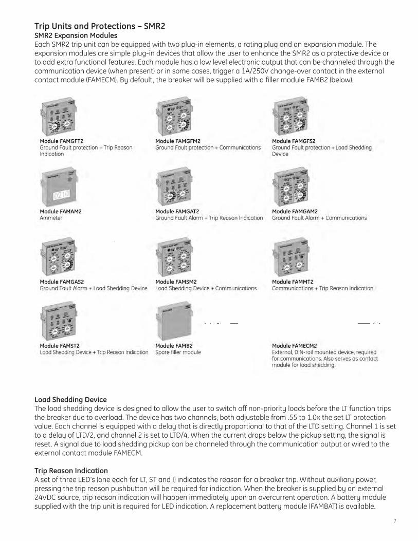
Trip Units and Protections – SMR2SMR2 Expansion ModulesEach SMR2 trip unit can be equipped with two plug-in elements, a rating plug and an expansion module. The expansion modules are simple plug-in devices that allow the user to enhance the SMR2 as a protective device or to add extra functional features. Each module has a low level electronic output that can be channeled through the communication device (when present) or in some cases, trigger a 1A/250V change-over contact in the external contact module (FAMECM). By default, the breaker will be supplied with a filler module FAMB2 (below).
Load Shedding DeviceThe load shedding device is designed to allow the user to switch off non-priority loads before the LT function trips the breaker due to overload. The device has two channels, both adjustable from .55 to 1.0x the set LT protection value. Each channel is equipped with a delay that is directly proportional to that of the LTD setting. Channel 1 is set to a delay of LTD/2, and channel 2 is set to LTD/4. When the current drops below the pickup setting, the signal is reset. A signal due to load shedding pickup can be channeled through the communication output or wired to the external contact module FAMECM.
Trip Reason IndicationA set of three LED’s (one each for LT, ST and I) indicates the reason for a breaker trip. Without auxiliary power, pressing the trip reason pushbutton will be required for indication. When the breaker is supplied by an external 24VDC source, trip reason indication will happen immediately upon an overcurrent operation. A battery module supplied with the trip unit is required for LED indication. A replacement battery module (FAMBAT) is available.

8
Overtemperature ProtectionAll SMR2 trip units have built-in temperature sensors that trip the breaker at internal temperatures above 90°C. The thermal memory tracks overheating, even after the device has tripped, and prevents the breaker from being switched on in environments above 90°C. A battery module (supplied with the trip unit) is required to enable this function. Replacement battery modules (FAMBAT) are available.
CommunicationsCommunicates breaker information including the following: Phase currents, position of all switches on the breaker, trip reason indication, load shedding signals, and zone selective interlock occurrences. For each breaker with Modbus RTU, the use of an internal communications module and an external contact module FAMECM is required. The FAMECM external contact module requires an external 24VDC power supply. For a complete list of communi-cated parameters, register map, and instructions, please see DEH-41181, the SMR2 Modbus User Manual.
Connections from SMR2 Trip Unit to FAMECM Communications Module
AmmeterThe ammeter provides the user with a measure of the current flowing through one of the breaker phases. The device has an accuracy of +/- 10% of full scale, and by default displays the current flowing through the most heavily loaded phase. Pushbuttons allow the user to scroll between phases.
External Power SupplyCommunications and Zone Selective Interlocking both require an external 24VDC power supply. An external supply will also enable automatic display of trip reason indication. A power supply assembly is available for AC supply voltages of 85-240VAC. The input to this assembly should be protected with 1/2A class CC fuses.
9
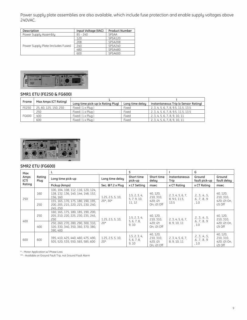
Power supply plate assemblies are also available, which include fuse protection and enable supply voltages above 240VAC.
Description Input Voltage (VAC) Product NumberPower Supply Assembly 85 - 240 SPSAA
Power Supply Plate (Includes Fuses)
120 SPSA120208 SPSA208240 SPSA240480 SPSA480600 SPSA600
SMR1 ETU (FE250 & FG600)
Frame Max Amps (CT Rating)L I
Long time pick-up (x Rating Plug) Long time delay Instantaneous Trip (x Sensor Rating)FE250 25, 60, 125, 150, 250 Fixed ( 1 x Plug ) Fixed 2, 3, 4, 5, 6, 7, 8, 9.5, 11.5, 13.5
FG600250 Fixed ( 1 x Plug ) Fixed 2, 3, 4, 5, 6, 7, 8, 9.5, 11.5, 13.5400 Fixed ( 1 x Plug ) Fixed 2, 3, 4, 5, 6, 7, 8, 9, 10, 11 600 Fixed ( 1 x Plug ) Fixed 2, 3, 4, 5, 6, 7, 8, 9, 10, 11
SMR2 ETU (FG600)Max Amps (CT) Rating
Rating Plug
L S I G
Long time pick-up Long time delay Short time pick-up
Short time delay
Instantaneous Trip
Ground fault pick-up
Ground fault delay
Pickup (Amps) Sec. @7.2 x Plug x LT Setting msec x CT Rating x CT Rating msec
250
160100, 104, 108, 112, 116, 120, 124, 128, 132, 136, 140, 144, 148, 152, 156, 160 1.25, 2.5, 5, 10,
20*, 30*
1.5, 2, 3, 4, 5, 7, 9, 10, 11, 12
40, 120, 210, 310, 420; i2t On, i2t Off
2, 3, 4, 5, 6, 7, 8, 9.5, 11.5, 13.5
.2, .3, .4, .5,
.6, .7, .8, .9 , 1.0
40, 120, 210, 310, 420; i2t On, i2t Off250
155, 165, 170, 175, 180, 190, 195, 200, 205, 215, 220, 225, 230, 240, 245, 250
400
250160, 165, 175, 180, 185, 190, 200, 205, 210, 220, 225, 230, 235, 245, 250 1.25, 2.5, 5, 10,
20*
1.5, 2, 3, 4, 5, 6, 7, 8, 9, 10
40, 120, 210, 310, 420; i2t On, i2t Off
2, 3, 4, 5, 6, 7, 8, 9, 10, 11
.2, .3, .4, .5,
.6, .7, .8, .9 , 1.0
40, 120, 210, 310, 420; i2t On, i2t Off400
250, 260, 270, 280, 290, 300, 310, 320, 330, 340, 350, 360, 370, 380, 390, 400
600 600 395, 410, 425, 440, 460, 475, 490, 505, 520, 535, 550, 565, 585, 600
1.25, 2.5, 5, 10, 20*
1.5, 2, 3, 4, 5, 6, 7, 8, 9, 10
40, 120, 210, 310, 420; i2t On, i2t Off
2, 3, 4, 5, 6, 7, 8, 9, 10, 11
.2, .3, .4, .5,
.6, .7, .8, .9 , 1.0
40, 120, 210, 310, 420; i2t On, i2t Off
* - Motor Application w/ Phase Loss** - Available on Ground Fault Trip, not Ground Fault Alarm

10
Internally Mounted Accessories
Record Plus internal accessories are common across the family, and are installed in specially designed sockets behind the front cover that allow installation without exposure to current carrying parts. Upon removal of the front cover, the breaker trips and will remain tripped until the cover is replaced. The sockets are accessed by removing the breaker front cover (held on by standard hardware). The sockets and accessories are labeled with distinctive markings to indicate into which pocket a particular accessory can be installed. One must only match the symbol on the accessory to the symbol on the breaker to install the accessory in the correct location.
Shunt Trip & Undervoltage Release
Shunt trip, bell alarm and auxiliary switch
The shunt trip is used to remotely open the circuit breaker. Like all other accessories, the shunt trip is UL listed for field installation and does not require exposure to current carrying parts for installation. Both the shunt trip and Undervoltage Release are low power consumption devices. Record Plus breakers feature a kiss-free design, which ensures that the primary contacts do not come into contact when a closing attempt is made with a shunt-trip or undervoltage release energized.
The undervoltage release is used to trip the circuit breaker when a control signal is removed, or drops below 35 – 70% of the rated voltage. If an attempt is made to re-close the circuit breaker without re-application of control power to the undervoltage release, the breaker will be held trip-free, preventing the contacts from closing.
It is not possible to install both an undervoltage release and shunt trip in the same breaker.
Configuration VoltageShunt Trip Undervoltage ReleaseCat. No. Inrush Power Cat. No. Inrush Power
12 VDC FASHTBW 200 mA / 2.4 W - -24 VAC / VDC FASHTDW 100 mA / 3.6 W FAUVRDW 50 mA / 1.2W48 VAC / VDC FASHTFW 60mA / 2.88 W FAUVRFW 20 mA / 0.96W110-130 VAC / 110-125 VDC FASHTJW 40 mA / 4.8 W FAUVRJW 15mA / 3.45W120 VAC* FASHTKW 40 mA / 4.8 W - -220-240VAC / 250VDC FASHTNW 20 mA / 4.6 W FAUVRNW 15mA / 3.45W277 VAC FASHT7W 11 mA / 3.0 W FAUVR7W 15mA / 4.0W400-480 VAC FASHTUW 20 mA / 8.4 W FAUVRUW 15mA / 6.3W
*FASHTKW Suitable for use with external ground fault sensing and relaying equipment (Operable at 55% of Rated Voltage)
Each shunt trip or undervoltage release is supplied with two #16 leads, 34" long. Blue for undervoltage releases, black for shunt trips.

11
Bell Alarm & Auxiliary SwitchThe Bell Alarm switch is used to signal a breaker trip operation. Common uses for bell alarm switches include indicating lights, external control relays, interlocking schemes, and any other application that requires remote indication of breaker trip. The switches are available in either normally open (NO) or normally closed (NC) configuration. Auxiliary switch contacts change position due to any operation of the circuit breaker (overcurrent trip, push to trip from the front cover, shunt trip/undervoltage release or toggle handle operation). Bell alarm contacts do not change position due to an operation of the toggle handle or push to trip button.
The auxiliary switch provides remote indication of the primary contact position. Auxiliary switches are commonly used anywhere remote indication of breaker position is desired. These switches are available in normally open (NO) and normally closed (NC) configurations; the contacts change position upon changing of position of the primary contacts regardless of method of operation.
Contact Configuration Description / Catalog Number Wire Color
1 NO (Form A)
Bell Alarm FABAM10W Yellow - Brown
Aux Switch - Left Mounted FAS10LW White - Red
Aux Switch - Right Mounted FAS10RW White - Red
1 NC (Form B)
Bell Alarm FABAM01W Yellow - Purple
Aux Switch - Left Mounted FAS01LW White - Brown/White
Aux Switch - Right Mounted FAS01RW White - Brown/White
All auxiliary and bell alarm switches are supplied with 34” of #16 wire, rated 600V.Switch ratings are as follows: 24VAC – 10A 24VDC – 2.5A120VAC – 6A 125VDC – 0.55A277VAC – 1.9A 250VDC – 0.27A
Accessory Mounting Locations and LimitationsFB 100
Accessory Mounting Pocket Location
Accessory Installation1 Pole 2 Pole 3 Pole
Shunt Trip or Undervoltage Release 0 1 1 Aux. Switch - Left Mount 0 0 1Aux. Switch - Right Mount 0 0 1Bell Alarm 0 0 1 Max. Number of Internal Accessories 0 4 4
Shunt Trip orUndervoltage Release
2 pole 3 pole
Bell AlarmSwitch
AuxiliarySwitches
FC 100
Accessory Mounting Pocket Location
Accessory Installation2 Pole* 3 Pole
Shunt Trip or Undervoltage Release 1 1 Aux. Switch - Left Mount 1 1Aux. Switch - Right Mount 1 1Bell Alarm 1 1 Max. Number of Internal Accessories 4 4
*2 Pole breaker in 3 Pole envelope
Shunt Trip orUndervoltage Release
2- or 3 pole
Bell AlarmSwitch
AuxiliarySwitches

12
FE 250
Accessory Mounting Pocket Location
Maximum Quantity
Shunt Trip or Undervoltage Release 1 Aux. Switch - Left Mount 2Aux. Switch - Right Mount 2 Bell Alarm Mechanism 1
Auxiliary Switch
Bell AlarmMechanism
Shunt Trip orUndervoltageRelease
Auxiliary Switch
FG 600
Accessory Mounting Pocket Location
Maximum Quantity
Shunt Trip or Undervoltage Release 1 Aux. Switch - Left Mount 3 Aux. Switch - Right Mount 2 Bell Alarm Mechanism 1 Bell Alarm Trip Unit 1
External Accessories
Termination Lugs
Termination lugs are available with / for Record Plus breakers that permit easy front connection of copper or aluminum insulated conductors to the breaker terminals. Lugs for FB, FC and FE frames are snap-in lugs that are held captive without hardware for ease of installation. FG lugs are mechanically attached to the circuit breaker terminals to provide sturdy connection of larger conductors.
Frame Amp Range Wire Range Lug Part Number
Lug Kit (Set of 3) Part Number Torque Specification Lug Kit (Set of 3) w/
Control Wire Terminal
FB 100 / FC 100
15-20 A 14-10 Cu / Al FCAL12 FCALK12 25 - 32 in*lb
25 - 60 A 10-4 Cu / Al FCAL13 FCALK13 25 - 32 in*lb
70 - 100 A 4 - 1/0 Cu / Al FCAL14 FCALK14 25 - 32 in*lb
FE 25020 - 150 A 14 - 3/0 Cu / Al FCAL15 FCALK15 150 in*lb FCALK15LV
175 - 250A #8 - 250 Cu / #8 - 350 Al FCAL16 FCALK16 275 in*lb FCALK16LV
FG 600 100- 600#8 - 400 Cu / #6 - 500Al (Top*) (Set of 3) FCALK318H #8 - #4 275 in*lb
2/0 - 600 Cu / Al (Bottom*) (Set of 2) FCALK218H #3 - 600 375 in*lb
*Top/Bottom holes in lug as shown
Top
Bottom
FCALK218H/FCALK318H
Auxiliary Switch
Bell AlarmMechanism
Shunt Trip orUndervoltageRelease
Bell AlarmTrip Unit
Auxiliary Switch
13
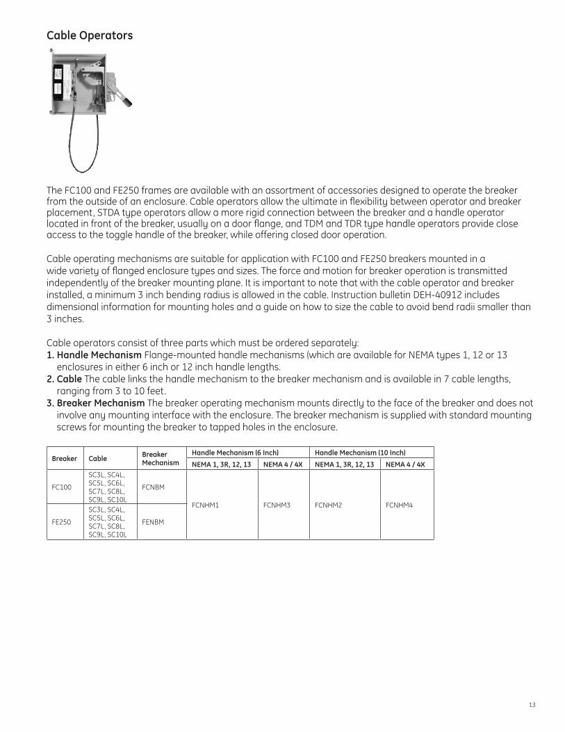
Cable Operators
The FC100 and FE250 frames are available with an assortment of accessories designed to operate the breaker from the outside of an enclosure. Cable operators allow the ultimate in flexibility between operator and breaker placement, STDA type operators allow a more rigid connection between the breaker and a handle operator located in front of the breaker, usually on a door flange, and TDM and TDR type handle operators provide close access to the toggle handle of the breaker, while offering closed door operation.
Cable operating mechanisms are suitable for application with FC100 and FE250 breakers mounted in a wide variety of flanged enclosure types and sizes. The force and motion for breaker operation is transmitted independently of the breaker mounting plane. It is important to note that with the cable operator and breaker installed, a minimum 3 inch bending radius is allowed in the cable. Instruction bulletin DEH-40912 includes dimensional information for mounting holes and a guide on how to size the cable to avoid bend radii smaller than 3 inches.
Cable operators consist of three parts which must be ordered separately: 1. Handle Mechanism Flange-mounted handle mechanisms (which are available for NEMA types 1, 12 or 13
enclosures in either 6 inch or 12 inch handle lengths. 2. Cable The cable links the handle mechanism to the breaker mechanism and is available in 7 cable lengths,
ranging from 3 to 10 feet. 3. Breaker Mechanism The breaker operating mechanism mounts directly to the face of the breaker and does not
involve any mounting interface with the enclosure. The breaker mechanism is supplied with standard mounting screws for mounting the breaker to tapped holes in the enclosure.
Breaker Cable Breaker Mechanism
Handle Mechanism (6 Inch) Handle Mechanism (10 Inch)
NEMA 1, 3R, 12, 13 NEMA 4 / 4X NEMA 1, 3R, 12, 13 NEMA 4 / 4X
FC100
SC3L, SC4L, SC5L, SC6L, SC7L, SC8L, SC9L, SC10L
FCNBM
FCNHM1 FCNHM3 FCNHM2 FCNHM4
FE250
SC3L, SC4L, SC5L, SC6L, SC7L, SC8L, SC9L, SC10L
FENBM

14
Flange Mounted Variable Depth Operators
STDA type operating handles and breaker mechanisms provide a flange-mounted handle that provides a more solid connection between the operating handle and the circuit breaker, but still offers enclosure depth flexibility (8 – 12 inches). Using a standard padlock, the handle can be padlocked in the “OFF” position.
The flange handle and operating mechanism must be ordered separately. An assortment of accessories are also available for the STDA type flange mounted handle operators.
Handle MechanismThe handles are of a rugged die cast construction, with double thick steel handles and large red/black plastic grip. O-ring seals are included for dirt-tight / oil-tight duty. The handles are available in either 6 or 10 inch sizes. Instruction bulletin GEH-5314 includes detailed handle drilling and installation instructions.
Breaker MechanismThe breaker mechanism kit consists of a cradle which is screw-mounted to the enclosure and a yoke assembly that interfaces with the breaker toggle handle. The breaker mechanism can be quickly re-configured in the field for mounting the handle to the left or right of the circuit breaker. Instruction bulletin DEH-40534 (FC) and DEH-41014 (FE) include detailed drilling and installation instructions, as well as instructions on how to custom-cut the drive rod to a length appropriate for the enclosure.
Breaker
Operating Handle Breaker Operating Mechanism
Flange Stiffener / Extended Drive Rod
Extended Drive Stud
Door Interlock Hardware Kits
NEMA 12/13
NEMA 4/4X Length Door
HingeNEMA 12/13
NEMA 4 / 4X
3rd Point Latch
FC100STDA1 STDA1X 6”
FCNFM TDSR TDS1Left TDV1 TDV1X
TDV3LSTDA2 STDA2X 10” Right TDV1L TDV1LX
FE250STDA1 STDA1X 6”
FENFM TDSR TDS1Left TDV1 TDV1X
TDV3LSTDA2 STDA2X 10” Right TDV1L TDV1LX
Additional Accessories• Flange Stiffener – Provides a rigid 3/8” rod between the handle operator and the breaker mechanism for
applications where the handle would not otherwise be rigidly supported• Extended Drive Rod – Extends the maximum breaker mounting plane to handle mounting plane to 18”• Extended Drive Stud – Permits further (by 1 5/16”) offset between the operating handle and the breaker
mechanism• Door Interlock Hardware Kits – Permits doors to be interlocked to circuit breaker position (Door will open only
when the circuit breaker is in the “OFF” position).
15
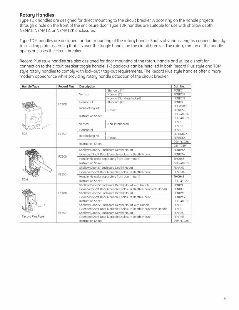
Rotary HandlesType TDR handles are designed for direct mounting to the circuit breaker. A door ring on the handle projects through a hole on the front of the enclosure door. Type TDR handles are suitable for use with shallow depth NEMA1, NEMA12, or NEMA12K enclosures.
Type TDM handles are designed for door mounting of the rotary handle. Shafts of various lengths connect directly to a sliding plate assembly that fits over the toggle handle on the circuit breaker. The rotary motion of the handle opens or closes the circuit breaker.
Record Plus style handles are also designed for door mounting of the rotary handle and utilize a shaft for connection to the circuit breaker toggle handle. 1-3 padlocks can be installed in both Record Plus style and TDM style rotary handles to comply with lock-out / tag-out requirements. The Record Plus style handles offer a more modern appearance while providing rotary handle actuation of the circuit breaker.
Handle Type Record Plus Description Cat. No.
TDR
FC100
VerticalStandard (4”) FCNRCNarrow (3”) FCNRCNNarrow (Non-Interlocked) FCNRCNI
Horizontal Standard (4”) FCNRD
Interlocking KitFCFRDRCK
Gasket SEFRGSK
Instruction SheetDEH-40914DEH-40919
FE250
Vertical Non-InterlockedFENRCFENRCI
Horizontal FENRD
Interlocking KitSEFRDRCK
Gasket SEFRGSK
Instruction SheetDEH-41028GEI-70594
TDM
FC100
Shallow Door (5” Enclosure Depth) Mount FCNRM2Extended Shaft Door (Variable Enclosure Depth) Mount FCNRM4Handle Kit (order separately from door mount) THCH45Instruction Sheet DEH-40913
FE250
Shallow Door (5” Enclosure Depth) Mount FENRM2Extended Shaft Door (Variable Enclosure Depth) Mount FENRM4Handle Kit (order separately from door mount) THCH45Instruction Sheet DEH-41027
Record Plus Type
FC100
Shallow Door (5” Enclosure Depth) Mount with Handle FCNRNExtended Shaft Door (Variable Enclosure Depth) Mount with Handle FCNRTShallow Door (5” Enclosure Depth) Mount FCNRM1Extended Shaft Door (Variable Enclosure Depth) Mount FCNRM3Instruction Sheet DEH-40517
FE250
Shallow Door (5” Enclosure Depth) Mount with Handle FENRHExtended Shaft Door (Variable Enclosure Depth) Mount with Handle FENRTShallow Door (5” Enclosure Depth) Mount FENRM1Extended Shaft Door (Variable Enclosure Depth) Mount FENRM3Instruction Sheet DEH-41025

16
Functions and Advantages
GeneralMolded Case Circuit BreakersMolded case circuit breakers are circuit protective devices that perform two primary functions. 1) automatic opening of the circuit breaker under overcurrent conditions, 2) opening/closing of a circuit by non-automatic means.
FunctionsA circuit breaker inherently protects circuits during short circuit and overload conditions by automatically opening its protected electrical circuit without the use of fuses. When the circuit breaker opens to clear a short circuit or a sustained overload condition, its toggle handle moves to the tripped position (midway between open and closed), indicating that the circuit breaker has automatically opened. Once the situation causing the overload or short circuit has been corrected, the circuit breaker may be reset by moving the toggle handle completely to the ‘off’ position before returning the handle to the ‘on’ position.
Circuit Breaker AdvantagesThere are several advantages to the use of circuit breakers as protective devices. One key advantage to circuit breakers is that an overcurrent condition on a single pole of a circuit breaker will result in the opening of all poles simultaneously. When using fusible devices for overcurrent protection, it is possible that an overcurrent on a single pole will result in opening of that phase only, thereby creating a phase imbalance that can potentially damage downstream equipment.
Molded Case Circuit Breakers (MCCB’s) are designed to be inherently trip-free when an overcurrent condition exists, or when an external tripping signal is being applied. Simply stated, if conditions exist such that the breaker should be open, it will not close, even if the toggle handle is forced into the ‘ON’ position.
ProtectionRecord Plus breakers utilize a unique combination of design features to offer the ultimate combination of protections in demanding electrical systems.
Current LimitationDesign features such as double break rotary contacts and reverse loop current paths make Record Plus among the most current limiting circuit breakers on the market today. When subjected to short circuit currents, the contacts are designed to “blow open” in response to the peak current levels. This mode of operation limits the amount of energy delivered to faulted conductors and downstream equipment to a fraction of that available. As an example, on a 480V system subjected to a 100kA fault (with a .2 power factor) will subject connected conductors and equipment to a peak current in excess of 200kA. With a current limiting FB circuit breaker, the peak current will be limited to less than 30kA.
The current limiting behavior of Record Plus breakers can benefit a user in three ways:1. The reduced let-thru energy can translate into reduced requirements for protection of personnel servicing the
electrical equipment and can potentially reduce HRC levels.2. Current limitation during a short circuit event can allow Record Plus breakers to ‘help’ downstream devices
clear faults they might not previously have been able to clear. See DET-008 for series ratings information including Record Plus breakers.
3. Current limitation, coupled with fast-acting but intelligent trip units, make Record Plus ideal for applications requiring total selectivity. A system employing Record Plus breakers has unprecedented potential to be both safe (reduced arc flash energy) and reliable (selective, even at instantaneous levels).

17
0.1 1 10 100 1000
Ip M
axim
um In
stan
tane
ous
Curr
ent (
kA)
1000.00
1.00
10.00
100.00
Available Three-Phase Symmetrical Short-Circuit Current (kA)
Non-Current Limited Peak Let-Thru (20% PF)
“Typical” 100A Current Limiting MCCB
FB100 Current Limiting MCCB
Full Let-thru Curves for Record Plus Circuit Breakers:Type Peak Let-Through I2T Let-ThroughFB100 DES-030 DES-031FC100 DES-030 DES-031FE250 DES-205 DES-206FG600 DES-040 DES-041
Basis of Interrupting Ratings
Short Circuit CurrentInterrupting ratings depend upon knowing the magnitude of the short circuit current that may flow through the circuit breaker. Devices rated in accordance with UL Standard 489 list their interrupting rating in terms of rms symmetrical amps. Devices rated in accordance with the IEC Standard 947-2 list both a “rated ultimate short circuit breaking capacity (Icu)” and a “rated service short circuit breaking capacity (Ics)” both in terms of rms symmetrical amps.
Differences between the IEC947-2 values of Icu (ultimate) and Ics (service) breaking capacities are based upon specific ratios of Ics to Icu, depending upon a number of factors, including whether the protective device is intentionally designed to incorporate time delay to provide selectivity to the protection system.
The procedures for calculating short circuit current and the X/R ratios are described in detail in GE Publication GET-3550.

18
Generally, electrical power system engineers calculate the X/R ratios rather than the power factors of protected circuits during short circuit studies. The magnitude of the momentary peak current to be interrupted is a function of the maximum peak current displacement from the zero current axis. That displacement is a function of the X/R ratio, the lower the power factor, the greater the magnitude of peak displacement.
Interrupting ratings of molded case circuit breakers are based upon a specific ratio of reactance to resistance, or a specific power factor. Since practical ac circuits contain some reactance, there is some displacement between current and voltage waveforms. Because a short circuit can literally occur during any point of the voltage wave, an actual trace of short circuit current may display considerable initial displacement from the zero axis.
In the figure below, the waveform at left shows a symmetrical ac current waveform that would occur if a purely resistive circuit was short circuited (or even a circuit containing reactance if the short circuit occurred at a precisely the right point in the voltage waveform, which is unlikely).
Zero Axis
Symmetrical AC waveform Asymmetrical AC waveform
Zero Axis
Axis ofSymmetry
The waveform on the right is a current trace of a short circuited ac circuit where displacement about the zero axis exists as a consequence of when the short circuit is applied and the amount of reactance in the short circuited circuit, compared to its resistance.
There is a simple relationship between the power factor of a short circuit and its X/R ratio. It is PF (in %) = R/Z x 100And Z=SQRT(R2+X2)Therefore:PF = (R / (R2 + X2))x100
The following table shows derating factors that must be applied to the maximum interrupting rating of Record Plus breakers when applied at varying power factors.
For example, a 65kA rated FB breaker, applied at any power factor greater than 20% need not be derated.
A 65kA rated FB breaker, applied at a power factor of 10% would have an adjusted interrupting rating of 65 x .88 = 57.2 kA

19
Power Factor (%)
X / R Ratio
Max. Interrupting Rating1-10 kA 11 - 20 kA 21 + kA
4 24.980 0.60 0.72 0.815 19.974 0.62 0.74 0.826 16.637 0.63 0.75 0.837 14.251 0.64 0.76 0.848 12.460 0.65 0.77 0.859 11.066 0.66 0.78 0.87
10 9.950 0.67 0.79 0.8811 9.036 0.68 0.80 0.8912 8.273 0.69 0.81 0.9013 7.627 0.69 0.82 0.9114 7.072 0.70 0.83 0.9315 6.591 0.71 0.84 0.9416 6.169 0.72 0.85 0.9517 5.797 0.73 0.85 0.9618 5.465 0.74 0.87 0.9719 5.167 0.75 0.88 0.9820 4.899 0.76 0.89 1.0021 4.656 0.77 0.90 1.0022 4.434 0.77 0.91 1.0023 4.231 0.78 0.92 1.0024 4.045 0.79 0.94 1.0025 3.873 0.80 0.95 1.0026 3.714 0.81 0.96 1.0027 3.566 0.82 0.97 1.0028 3.429 0.83 0.98 1.0029 3.300 0.83 0.99 1.0030 3.180 0.84 1.00 1.0031 3.067 0.85 1.00 1.0032 2.961 0.86 1.00 1.0033 2.861 0.87 1.00 1.0034 2.766 0.88 1.00 1.0035 2.676 0.88 1.00 1.0036 2.592 0.89 1.00 1.0037 2.511 0.90 1.00 1.0038 2.434 0.91 1.00 1.0039 2.361 0.91 1.00 1.0040 2.291 0.92 1.00 1.0041 2.225 0.93 1.00 1.0042 2.161 0.94 1.00 1.0043 2.100 0.95 1.00 1.0044 2.041 0.95 1.00 1.0045 1.984 0.96 1.00 1.0046 1.930 0.97 1.00 1.0047 1.878 0.97 1.00 1.0048 1.828 0.98 1.00 1.0049 1.779 0.99 1.00 1.0050 1.732 1.00 1.00 1.00

20
Blow-Open ContactsAll Record Plus breakers feature current limiting construction that, under short circuit conditions, will provide opening of the breaker in a sufficiently rapid manner as to affect the current flow during the first ½ cycle of short circuit current. The contact arms and rotary contact structure are constructed so that under short circuit current, the contacts are propelled apart by the current itself. When short circuit current flows through the contact structure, forces proportional to the square of the current act to ‘blow open’ the moving contact arms. The higher the fault current, the higher the force. During maximum fault conditions, contact seperation typically occurs within four milliseconds and the arc is typically fully quenched within 8 milliseconds.
Peak let-thru current is typically held to less than 45% of the maximum available peak current, resulting in a tremendous reduction in the amount of energy delivered to conductors and associated equipment.
Thermal-Magnetic Trip UnitsThermal-magnetic trip units that are compact and cost efficient provide the protection functions for the FB100 and FC100 trip units. The thermal portion of these trip units use a mechanical element composed of dissimilar metals that respond differently to temperature. The mechanical / thermal nature of these elements make them inherently immune to electrically noisy circuits such as those with a high level of harmonic distortion.
The magnetic elements in these thermal-magnetic trip units provide the overcurrent protection during a short-circuit. The capability of an electromagnet to respond differently depending upon the amount of current flowing through it is utilized to produce a mechanical motion that is proportional to the current. The mechanical motion of the magnet is then used to operate the circuit breaker mechanism thereby causing the contacts to open.
Electronic Trip UnitsElectronic trip units that offer sophisticated protective functions and wide setting bands are standard protection devices for the FE250 and FG600 frame sizes. Each electronic device has been designed with the abnormalities of modern low voltage distribution circuits in mind and has been rigorously tested to cope with harmonic currents, electromagnetic fields, inrush currents and spikes, thus preventing phenomena such as incorrect current measurement and nuisance tripping. The devices exist in multiple performance tiers, the SMR1 for the FE and FG frames, and the SMR2 for the FG 600 frames.
The advent of cost effective microprocessors has enabled manufacturers of molded case circuit breakers to offer products containing solid-state trip units. There are a number of advantages to using solid-state circuitry in the trip circuitry of a circuit breaker. These advantages include:• Higher levels of accuracy in establishing specific tripping points• Ability to shape instantaneous, short time, and long time tripping current versus time curves to obtain better
protection, better selectivity, or both• Ability to provide better user adjustment of tripping points• Ability to provide sensing and tripping circuitry that is ambient insensitiveThese advantages are generic to any well-engineered molded case circuit breaker and solid state tripping system. The accuracy and flexibility of these trip units make them the logical choice where coordination and accurate protection are required.
RMS Sensing and Peak SensingMany modern electrical loads (from computers and fax machines to variable frequency drives) are capable of applying harmonic distortion to the electrical distribution system. In fact, harmonics can even be transmitted between facilities and affect equipment in nearby locations.
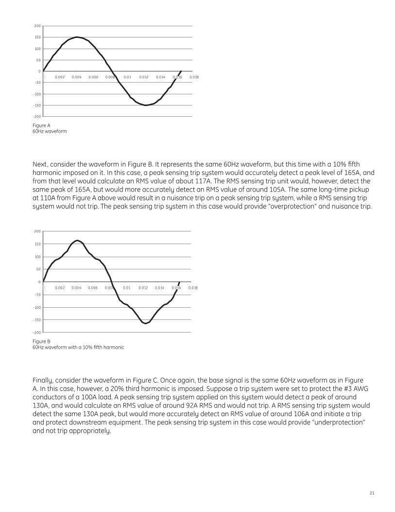
As an example, consider the waveform in Figure A. It represents an ideal 60 Hz waveform with a 150A peak. A trip system based on either RMS or peak sensing would measure this waveform and compute a 150A peak, and a RMS value of about 105A. With a long-time pickup set, for example, at 110A, both the RMS sensing and peak sensing trip unit would provide adequate protection.
21
-200
-150
-100
-50
0
50
100
150
200
0 0.002 0.004 0.006 0.008 0.01 0.012 0.014 0.016 0.018
Figure A60Hz waveform
Next, consider the waveform in Figure B. It represents the same 60Hz waveform, but this time with a 10% fifth harmonic imposed on it. In this case, a peak sensing trip system would accurately detect a peak level of 165A, and from that level would calculate an RMS value of about 117A. The RMS sensing trip unit would, however, detect the same peak of 165A, but would more accurately detect an RMS value of around 105A. The same long-time pickup at 110A from Figure A above would result in a nuisance trip on a peak sensing trip system, while a RMS sensing trip system would not trip. The peak sensing trip system in this case would provide “overprotection” and nuisance trip.
-200
-150
-100
-50
0
50
100
150
200
0 0.002 0.004 0.006 0.008 0.01 0.012 0.014 0.016 0.018
Figure B60Hz waveform with a 10% fifth harmonic
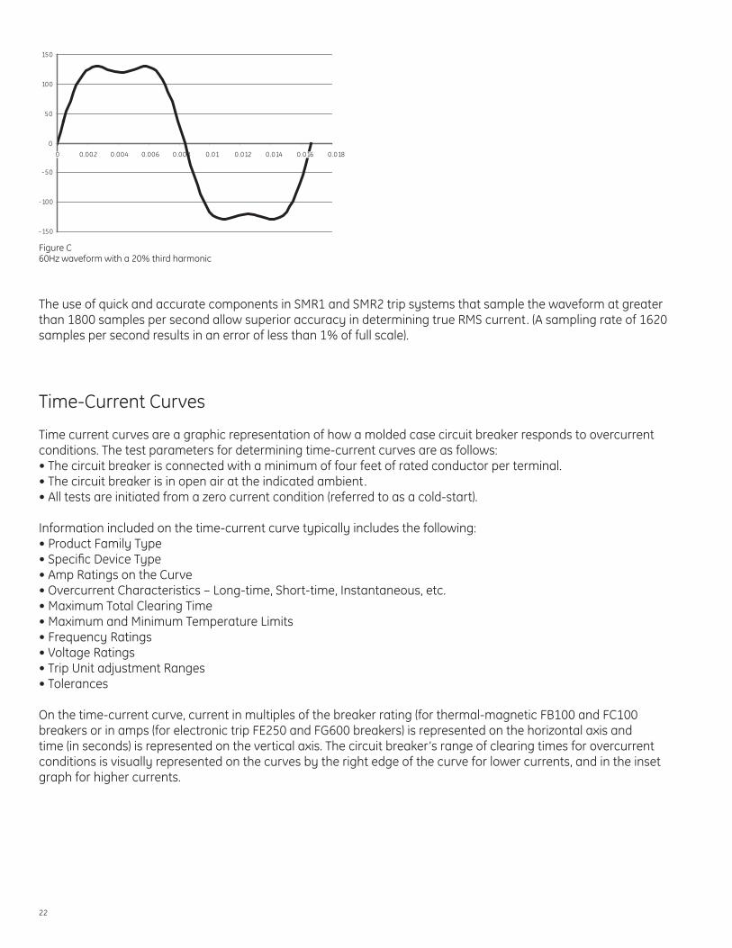
Finally, consider the waveform in Figure C. Once again, the base signal is the same 60Hz waveform as in Figure A. In this case, however, a 20% third harmonic is imposed. Suppose a trip system were set to protect the #3 AWG conductors of a 100A load. A peak sensing trip system applied on this system would detect a peak of around 130A, and would calculate an RMS value of around 92A RMS and would not trip. A RMS sensing trip system would detect the same 130A peak, but would more accurately detect an RMS value of around 106A and initiate a trip and protect downstream equipment. The peak sensing trip system in this case would provide “underprotection” and not trip appropriately.
22
-150
-100
-50
0
50
100
150
0 0.002 0.004 0.006 0.008 0.01 0.012 0.014 0.016 0.018
Figure C60Hz waveform with a 20% third harmonic
The use of quick and accurate components in SMR1 and SMR2 trip systems that sample the waveform at greater than 1800 samples per second allow superior accuracy in determining true RMS current. (A sampling rate of 1620 samples per second results in an error of less than 1% of full scale).
Time-Current Curves
Time current curves are a graphic representation of how a molded case circuit breaker responds to overcurrent conditions. The test parameters for determining time-current curves are as follows:• The circuit breaker is connected with a minimum of four feet of rated conductor per terminal.• The circuit breaker is in open air at the indicated ambient.• All tests are initiated from a zero current condition (referred to as a cold-start).
Information included on the time-current curve typically includes the following:• Product Family Type• Specific Device Type• Amp Ratings on the Curve• Overcurrent Characteristics – Long-time, Short-time, Instantaneous, etc.• Maximum Total Clearing Time• Maximum and Minimum Temperature Limits• Frequency Ratings• Voltage Ratings• Trip Unit adjustment Ranges• Tolerances
On the time-current curve, current in multiples of the breaker rating (for thermal-magnetic FB100 and FC100 breakers or in amps (for electronic trip FE250 and FG600 breakers) is represented on the horizontal axis and time (in seconds) is represented on the vertical axis. The circuit breaker’s range of clearing times for overcurrent conditions is visually represented on the curves by the right edge of the curve for lower currents, and in the inset graph for higher currents.

23
24
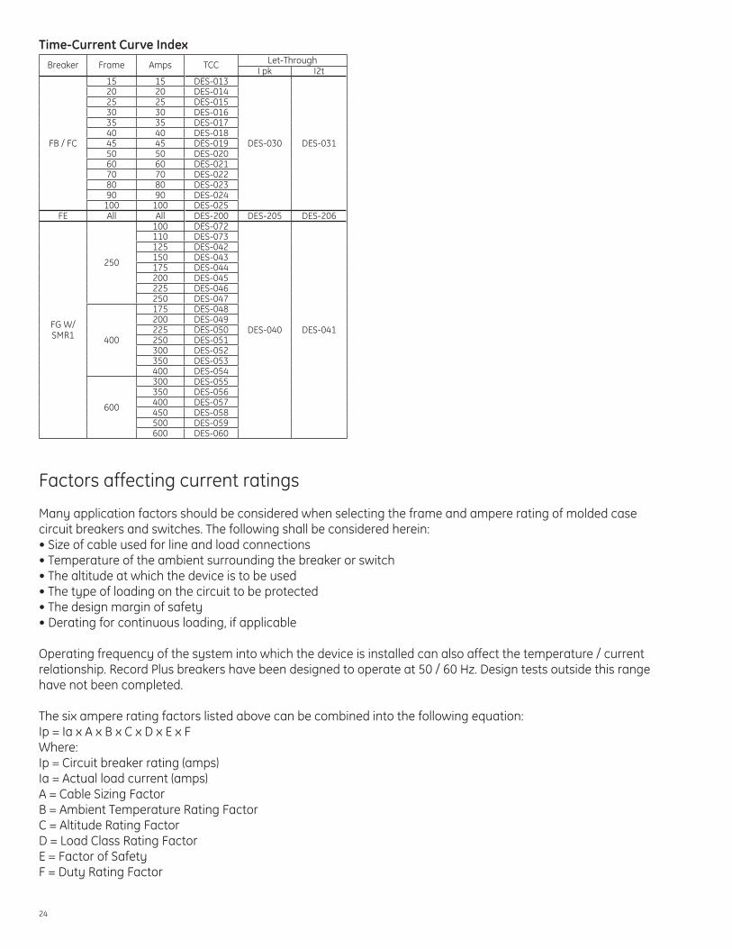
Time-Current Curve IndexBreaker Frame Amps TCC Let-Through
I pk I2t
FB / FC
15 15 DES-013
DES-030 DES-031
20 20 DES-01425 25 DES-01530 30 DES-01635 35 DES-01740 40 DES-01845 45 DES-01950 50 DES-02060 60 DES-02170 70 DES-02280 80 DES-02390 90 DES-024
100 100 DES-025FE All All DES-200 DES-205 DES-206
FG W/ SMR1
250
100 DES-072
DES-040 DES-041
110 DES-073125 DES-042150 DES-043175 DES-044200 DES-045225 DES-046250 DES-047
400
175 DES-048200 DES-049225 DES-050250 DES-051300 DES-052350 DES-053400 DES-054
600
300 DES-055350 DES-056400 DES-057450 DES-058500 DES-059600 DES-060
Factors affecting current ratings
Many application factors should be considered when selecting the frame and ampere rating of molded case circuit breakers and switches. The following shall be considered herein:• Size of cable used for line and load connections• Temperature of the ambient surrounding the breaker or switch• The altitude at which the device is to be used• The type of loading on the circuit to be protected• The design margin of safety• Derating for continuous loading, if applicable
Operating frequency of the system into which the device is installed can also affect the temperature / current relationship. Record Plus breakers have been designed to operate at 50 / 60 Hz. Design tests outside this range have not been completed.
The six ampere rating factors listed above can be combined into the following equation:Ip = Ia x A x B x C x D x E x FWhere:Ip = Circuit breaker rating (amps)Ia = Actual load current (amps)A = Cable Sizing FactorB = Ambient Temperature Rating FactorC = Altitude Rating FactorD = Load Class Rating FactorE = Factor of SafetyF = Duty Rating Factor
25
Each of the six factors are quantified in the following pages:
Cable Sizing – Factor AMolded case circuit breakers are designed to protect insulated cable. The characteristics of breakers are therefore closely tied to Underwriters Laboratories specified size and type of wire for each rating.
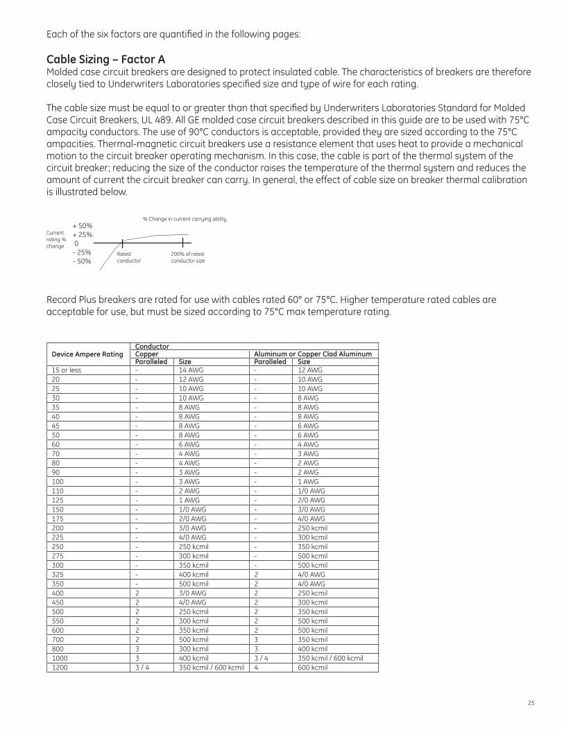
The cable size must be equal to or greater than that specified by Underwriters Laboratories Standard for Molded Case Circuit Breakers, UL 489. All GE molded case circuit breakers described in this guide are to be used with 75°C ampacity conductors. The use of 90°C conductors is acceptable, provided they are sized according to the 75°C ampacities. Thermal-magnetic circuit breakers use a resistance element that uses heat to provide a mechanical motion to the circuit breaker operating mechanism. In this case, the cable is part of the thermal system of the circuit breaker; reducing the size of the conductor raises the temperature of the thermal system and reduces the amount of current the circuit breaker can carry. In general, the effect of cable size on breaker thermal calibration is illustrated below.
Ratedconductor
200% of ratedconductor size
% Change in current carrying ability
Currentrating %change
+ 50%+ 25% 0- 25%- 50%
Record Plus breakers are rated for use with cables rated 60° or 75°C. Higher temperature rated cables are acceptable for use, but must be sized according to 75°C max temperature rating.
Device Ampere RatingConductorCopper Aluminum or Copper Clad AluminumParalleled Size Paralleled Size
15 or less - 14 AWG - 12 AWG20 - 12 AWG - 10 AWG25 - 10 AWG - 10 AWG30 - 10 AWG - 8 AWG35 - 8 AWG - 8 AWG40 - 8 AWG - 8 AWG45 - 8 AWG - 6 AWG50 - 8 AWG - 6 AWG60 - 6 AWG - 4 AWG70 - 4 AWG - 3 AWG80 - 4 AWG - 2 AWG90 - 3 AWG - 2 AWG100 - 3 AWG - 1 AWG110 - 2 AWG - 1/0 AWG125 - 1 AWG - 2/0 AWG150 - 1/0 AWG - 3/0 AWG175 - 2/0 AWG - 4/0 AWG200 - 3/0 AWG - 250 kcmil225 - 4/0 AWG - 300 kcmil250 - 250 kcmil - 350 kcmil275 - 300 kcmil - 500 kcmil300 - 350 kcmil - 500 kcmil325 - 400 kcmil 2 4/0 AWG350 - 500 kcmil 2 4/0 AWG400 2 3/0 AWG 2 250 kcmil450 2 4/0 AWG 2 300 kcmil500 2 250 kcmil 2 350 kcmil550 2 300 kcmil 2 500 kcmil600 2 350 kcmil 2 500 kcmil700 2 500 kcmil 3 350 kcmil800 3 300 kcmil 3 400 kcmil1000 3 400 kcmil 3 / 4 350 kcmil / 600 kcmil1200 3 / 4 350 kcmil / 600 kcmil 4 600 kcmil
26
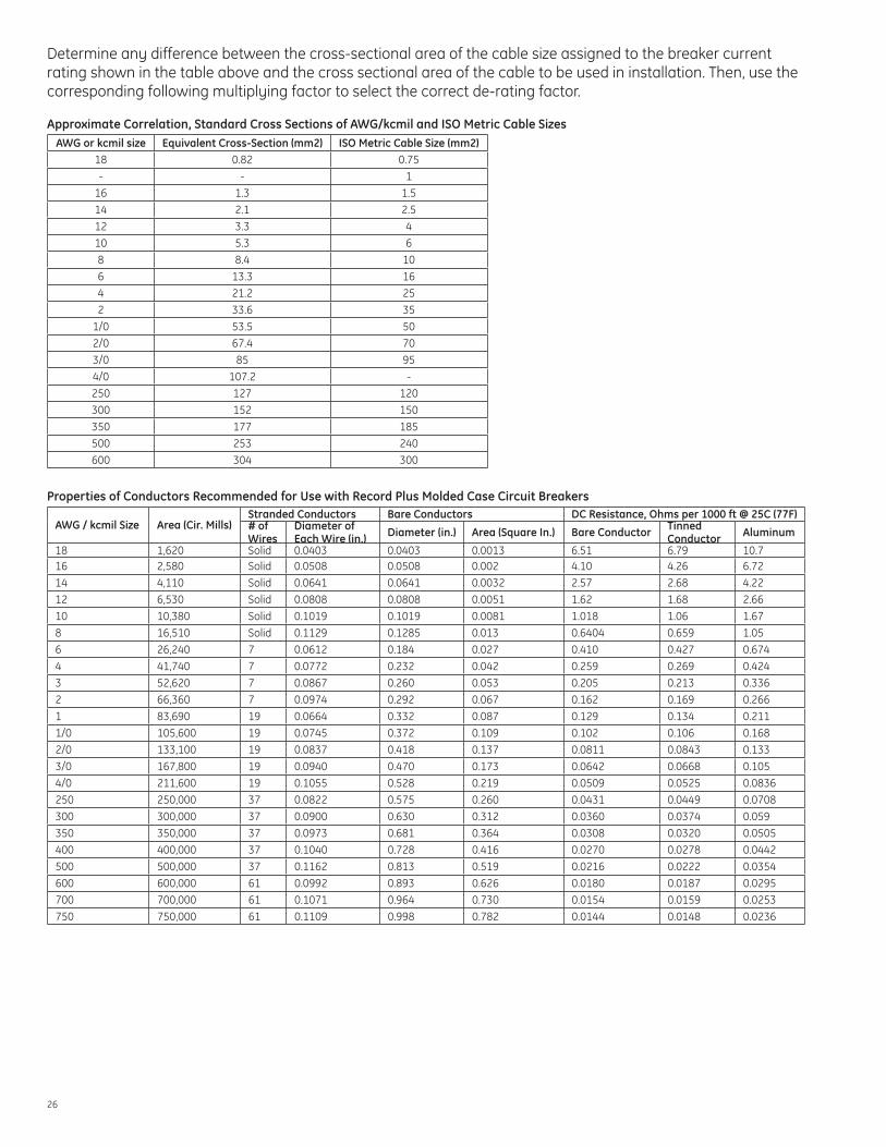
Determine any difference between the cross-sectional area of the cable size assigned to the breaker current rating shown in the table above and the cross sectional area of the cable to be used in installation. Then, use the corresponding following multiplying factor to select the correct de-rating factor.
Approximate Correlation, Standard Cross Sections of AWG/kcmil and ISO Metric Cable SizesAWG or kcmil size Equivalent Cross-Section (mm2) ISO Metric Cable Size (mm2)
18 0.82 0.75
- - 1
16 1.3 1.5
14 2.1 2.5
12 3.3 4
10 5.3 6
8 8.4 10
6 13.3 16
4 21.2 25
2 33.6 35
1/0 53.5 50
2/0 67.4 70
3/0 85 95
4/0 107.2 -
250 127 120300 152 150350 177 185500 253 240600 304 300
Properties of Conductors Recommended for Use with Record Plus Molded Case Circuit Breakers
AWG / kcmil Size Area (Cir. Mills)Stranded Conductors Bare Conductors DC Resistance, Ohms per 1000 ft @ 25C (77F)# of Wires
Diameter of Each Wire (in.) Diameter (in.) Area (Square In.) Bare Conductor Tinned
Conductor Aluminum
18 1,620 Solid 0.0403 0.0403 0.0013 6.51 6.79 10.716 2,580 Solid 0.0508 0.0508 0.002 4.10 4.26 6.7214 4,110 Solid 0.0641 0.0641 0.0032 2.57 2.68 4.2212 6,530 Solid 0.0808 0.0808 0.0051 1.62 1.68 2.6610 10,380 Solid 0.1019 0.1019 0.0081 1.018 1.06 1.678 16,510 Solid 0.1129 0.1285 0.013 0.6404 0.659 1.056 26,240 7 0.0612 0.184 0.027 0.410 0.427 0.6744 41,740 7 0.0772 0.232 0.042 0.259 0.269 0.4243 52,620 7 0.0867 0.260 0.053 0.205 0.213 0.3362 66,360 7 0.0974 0.292 0.067 0.162 0.169 0.2661 83,690 19 0.0664 0.332 0.087 0.129 0.134 0.2111/0 105,600 19 0.0745 0.372 0.109 0.102 0.106 0.168
2/0 133,100 19 0.0837 0.418 0.137 0.0811 0.0843 0.1333/0 167,800 19 0.0940 0.470 0.173 0.0642 0.0668 0.105
4/0 211,600 19 0.1055 0.528 0.219 0.0509 0.0525 0.0836250 250,000 37 0.0822 0.575 0.260 0.0431 0.0449 0.0708
300 300,000 37 0.0900 0.630 0.312 0.0360 0.0374 0.059
350 350,000 37 0.0973 0.681 0.364 0.0308 0.0320 0.0505
400 400,000 37 0.1040 0.728 0.416 0.0270 0.0278 0.0442
500 500,000 37 0.1162 0.813 0.519 0.0216 0.0222 0.0354600 600,000 61 0.0992 0.893 0.626 0.0180 0.0187 0.0295
700 700,000 61 0.1071 0.964 0.730 0.0154 0.0159 0.0253
750 750,000 61 0.1109 0.998 0.782 0.0144 0.0148 0.0236

27
In order to apply the de-rating factor, Factor A, determine any difference between the cross-sectional area of the cable size assigned to the breaker or switch current rating shown in the Wire Size by Amp Rating table in this section and the cross-sectional area of the cable used in the installation. Then select the appropriate cable sizing selection factor from the table below:
Percentage of Rated Cross-Sectional Area Derating Factor
50 1.40
60 1.25
70 1.15
80 1.07
90 1.02
100 1.00
125 0.99
150 0.97
200 0.97
Ambient Temperature – Factor BAmbient temperature has a wider effect on the rating of the circuit breaker / cable system than making an exact match of the actual versus rated cable sizes. The term “ambient” temperature always refers to the temperature of the air immediately surrounding the protective device itself, not the temperature outside the device’s enclosure.
FB and FC breakers are “Enclosure Compensated” and, as such, their time-current curves reflect performance at an ambient of 40°C. Included on each curve is a key in the upper left corner that indicates how the x-axis of the curve should be shifted for ambients ranging from 0° to 60°C.
FE and FG breakers are equipped with electronic trip units and are not affected by ambient temperatures. There are, however, factors that should be applied to protect the devices from temperatures that could be potentially harmful to operators or to materials inside the circuit breaker.
Once the ambient temperature is determined, select the ambient temperature factor from the table below. It is important to note that the table below assumes that 90°C rated wire, sized according to the 75°C table, will be used for ambients above 40°C.
Factor BAmbient Temperature (°C) FB/FC FE FG25 1.00 1.00 1.0040 1.00 1.00 1.00
50 1.04 1.09 1.1060 1.11 1.18 1.21
70 1.33 1.34 1.38
Altitude – Factor CRecord Plus breakers do not require any derating for altitudes below 6,000 feet. Reduced air density at altitudes above this affect the heat transfer out of the breaker. Use the table below to determine the necessary derating factor related to the installation altitude.
Installation AltitudeDerating Factor
Feet Meters-100 - 6000 -30 - 1800 1.00
6001 - 10000 1801 - 3000 1.04
10000 + 3000 + 1.08

28
Load Class – Factor DThe table below lists six different load class factors. A specific load may involve more than one of these factors. For example, a group mounted circuit breaker may be protecting a circuit that includes a normal duty motor branch circuit. In this case, one would multiply the derating factor for group mounting by the derating factor for normal duty single motor branch circuit protection (1.10 x 1.25 = 1.375). 1.375 would be the appropriate derating factor due to the load class.
Load Type Derating FactorGroup Mounted (12 or more breakers) 1.10
Switching Capacitors 1.50
Switching Electromagnets 1.50
Single Motor Branch Circuit Protection (Normal Duty) 1.25
Single Motor Branch Circuit Protection (Heavy Duty) 1.75
All other Load Types (Normal Duty) 1.00
Safety Factor – Factor ESafety factor is used to provide a design margin between the rating limit of a circuit breaker and the derived operating current calculated using all of the selection factors described in the derating equation.A factor of safety of 10% is recommended to prevent nuisance tripping.
Intermittent / Continuous Duty Rating – Factor FIn those applications governed by UL rules and the National Electrical Code (NEC), an additional rating factor is necessary for standard-rated circuit breakers. This factor differentiates between continuous and intermittent duty.
When a circuit breaker is installed in an intermittent duty application, the duty rating factor is 1.00. Intermittent duty is defined as operation under rated load for a period of not more than three hours, followed by a period of no-load operation, followed by a period of rest. The time periods of no load and rest are undefined by the NEC. Some authorities suggest that the use of a three-hour period of no-load operation after the three-hour, full-load operation meets the intent of the term “intermittent.”
Continuous duty generally means operation without any time limit whatsoever, however, for purposes of rated molded-case circuit breakers, operation at rated loads for periods of time in excess of three hours is considered continuous duty. The duty rating factor for Record Plus breakers, as standard rated devices, in continuous duty application is 1.25.
Load Type Derating FactorContinuous (operation at constant load for greater than three hours) 1.25Intermittent (operation at constant load for 3 hours or less) 1.00

29
Nomenclature Guide
Breaker Catalog NumberRecord Plus Family
Frame Size (Maximum Amps)
Interrupt Tier (kA @ 480VAC Shown)
Pole Construction Rated Voltage Trip Unit Type Rated Amps* Connection
F B - 100 S - 25kA 1 - 1 Pole 4 - 480 VAC TE - Thermal - Magnetic 015 - 100 (FB / FC) R / R0 - Standard, No Lugs
C - 100 V - 35kA 2 - 2 Pole 6 - 600 VAC AA - SMR1 Electronic 100 - 600 (FE / FG) R1 - Breaker with Line and Load Lugs
E - 250 N - 65kA 3 - 3 Pole KA - SMR2 Electronic R2 - Breaker with Load Lugs
G - 600 H - 100kA 32 - 2 Pole in 3-Pole Frame **
KZ - SMR2 Electronic with ZSI
R3 - Breaker with Line Lugs
L - 150kA 20 - 2-Pole Molded Case Switch **
F0 - Molded Case Switch **
RV - Breaker with Line Side Terminals for GE type AD Lighting Panels and Load Lugs
P - 200kA 30 - 3-Pole Molded Case Switch **
Y - 150kA MCS **
* - Breaker Rating for FB / FC, CT Rating for FE / FG** - Molded Case Switch only available in 60 and 100A FC Frames
Rating Plug Catalog NumberRecord Plus
FamilyFrame Size
(Maximum Amps) Accessory Type Adjustability Pole Construction CT Max Amps Rated Amps
F B - N/A No Plug Necessary R - Rating Plug P - SMR1 - Fixed,
Non Adjustable3 - SMR1 Trip Unit 3
or 2 Pole B - 25 (FE) 0025 - 0250 (FE)
C - N/A No Plug Necessary
M - SMR2 - Fixed, Non Adjustable
3 - SMR2 Trip Unit 3 Pole D - 60 (FE) 0100 - 0600
(FG)
E - 250N - SMR2
Adjustable LT PU and Delay
2 - SMR2 Trip Unit 2 Pole G - 125 (FE)
G - 600 H - 150 (FE)
Note: This information is provided for interpreting product numbers (it should not be used to build catalog nummbers).
SMR2 Expansion Modules (If Needed)See page 7
Internal AccessoriesSee pages 10-11
Mounting Hardware and External AccessoriesSee pages 12-15
30
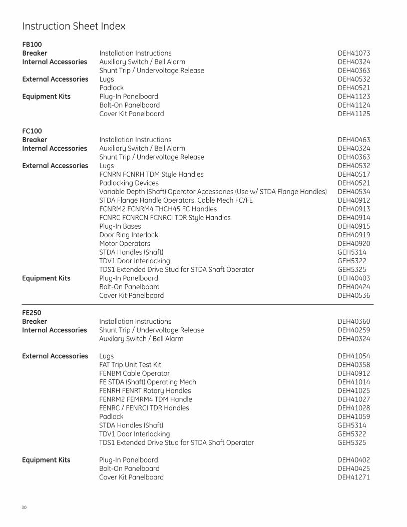
Instruction Sheet Index
FB100Breaker Installation Instructions DEH41073Internal Accessories Auxiliary Switch / Bell Alarm DEH40324 Shunt Trip / Undervoltage Release DEH40363External Accessories Lugs DEH40532 Padlock DEH40521Equipment Kits Plug-In Panelboard DEH41123 Bolt-On Panelboard DEH41124 Cover Kit Panelboard DEH41125
FC100Breaker Installation Instructions DEH40463 Internal Accessories Auxiliary Switch / Bell Alarm DEH40324 Shunt Trip / Undervoltage Release DEH40363External Accessories Lugs DEH40532 FCNRN FCNRH TDM Style Handles DEH40517 Padlocking Devices DEH40521 Variable Depth (Shaft) Operator Accessories (Use w/ STDA Flange Handles) DEH40534 STDA Flange Handle Operators, Cable Mech FC/FE DEH40912 FCNRM2 FCNRM4 THCH45 FC Handles DEH40913 FCNRC FCNRCN FCNRCI TDR Style Handles DEH40914 Plug-In Bases DEH40915 Door Ring Interlock DEH40919 Motor Operators DEH40920 STDA Handles (Shaft) GEH5314 TDV1 Door Interlocking GEH5322 TDS1 Extended Drive Stud for STDA Shaft Operator GEH5325Equipment Kits Plug-In Panelboard DEH40403 Bolt-On Panelboard DEH40424 Cover Kit Panelboard DEH40536
FE250 Breaker Installation Instructions DEH40360Internal Accessories Shunt Trip / Undervoltage Release DEH40259 Auxilary Switch / Bell Alarm DEH40324
External Accessories Lugs DEH41054 FAT Trip Unit Test Kit DEH40358 FENBM Cable Operator DEH40912 FE STDA (Shaft) Operating Mech DEH41014 FENRH FENRT Rotary Handles DEH41025 FENRM2 FEMRM4 TDM Handle DEH41027 FENRC / FENRCI TDR Handles DEH41028 Padlock DEH41059 STDA Handles (Shaft) GEH5314 TDV1 Door Interlocking GEH5322 TDS1 Extended Drive Stud for STDA Shaft Operator GEH5325
Equipment Kits Plug-In Panelboard DEH40402 Bolt-On Panelboard DEH40425 Cover Kit Panelboard DEH41271

31
FG600Breaker Installation Instructions DEH41177Internal Accessories Shunt Trip / Undervoltage Release DEH40259 Auxilary Switch / Bell Alarm DEH40324External Accessories Padlock DEH41031 FAT Trip Unit Test Kit DEH40358 Lug Kits DEH40404SMR2 SMR2 Expansion Modules DEH40408 SMR2 Modbus User Manual DEH41181 SMR2 External Contact Module DEH40409Equipment Kits Plug-In Panelboard Single Branch DEH40420 Plug-in Panelboard Double Branch DEH40419 Bolt-On Panelboard Single Branch DEH40426 Bolt-On Panelboard Double Branch DEH41047 Cover Kit Panelboard DEH41074

GE41 Woodford Avenue, Plainville, CT 06062www.geelectrical.com
© 2009 General Electric Company
imagination at work
Information provided is subject to change without notice. Please verify all details with GE. All values are design or typical values when measured under laboratory conditions, and GE makes no warranty or guarantee, express or implied, that such performance will be obtained under end-use conditions.
DET-720 (11/09)