reconnaissance report on the mw 7.5 hindu kush earthquake
TRANSCRIPT

United Arab Emirates University
Reconnaissance report on the Mw 7.5 Hindu Kush earthquake of 26th October
2015 and the subsequent aftershocks Technical Report
by
Najif Ismail, MEERI CPEng MIPENZ
and Nouman Khattak MPEC
12/26/2015
Department of Civil and Environmental Engineering
Faculty of Engineering, United Arab Emirates University
PO Box 15551, Al Ain United Arab Emirates
www.uaeu.ac.ae

1
About authors
Najif Ismail is an Assistant Professor in the Department of Civil and Environmental
Engineering at the United Arab Emirates University. Najif obtained his PhD from the
University of Auckland in 2012, having previously completed his BE (Hons) and ME
from the University of Engineering and Technology Taxila. Najif also has finished a
formal teaching qualification from the Otago Polytechnic. He was awarded the 2013
Best Doctoral Dissertation Award by the Masonry Society (USA) and the 2013 OP
Staff Award for Excellence in Research. Najif has contributed to several reports
including the one submitted to Canterbury Earthquakes Royal Commission, reporting
the seismic performance of buildings during the 2010/2011 Canterbury earthquake
series. He has also served on the masonry subcommittee for 2013 revision of ASCE -
41 standards. Najif’s primary research interests are associated with seismic assessment
and retrofit of concrete and masonry structures, and sustainable concrete technology.
Over the last 1 year Najif has led a project considering the seismic assessment and
retrofit of infilled concrete frame buildings, funded by the United Arab Emirates
University research grant G00001603.
Nouman Khattak is a Research Assistant at the United Arab Emirates University,
working on the research project investigating seismic assessment and retrofit of
infilled concrete frame buildings, funded through the United Arab Emirates University
research grant G00001603. Nouman has completed his ME and BE from the
University of Engineering and Technology Peshawar. Nouman has have experience of
working on a range of projects as consulting engineer prior to starting his academic
position at the United Arab Emirates University.

2
Table of contents
Abstract ....................................................................................................................................................... 3
Acknowledgement ...................................................................................................................................... 4
1 Introduction.......................................................................................................................................... 5
2 Seismicity of the region ....................................................................................................................... 7
3 Strong motion records.......................................................................................................................... 8
4 Building inventory of earthquake affected region ............................................................................. 10
5 Characterisation of building diaphragms ........................................................................................... 11
6 Building typologies and associated damage patterns ........................................................................ 11
6.1 Adobe buildings ......................................................................................................................... 12
6.2 USM buildings ........................................................................................................................... 13
6.3 URM buildings ........................................................................................................................... 14
6.4 UCM buildings ........................................................................................................................... 17
6.5 TLM buildings............................................................................................................................ 18
6.6 CON-URM Buildings ................................................................................................................ 18
6.7 RCC buildings ............................................................................................................................ 19
6.8 SF buildings................................................................................................................................ 21
7 Concluding remarks ........................................................................................................................... 21
8 References.......................................................................................................................................... 23

3
Abstract
The M7.5 Hindu Kush earthquake of 26th October, 2015 caused widespread damage in Afghanistan and
northern region of Pakistan. The earthquake resulted due to reveres faulting at an intermediate depth of
210 km within the northeast-trending tabular zone underneath the Hindu Kush region of Afghanistan.
The damage was mostly concentrated in Khyber Pakhtunkhwa, Federally Administered Tribal Areas
and Gilgit-Baltistan. Immediately after the earthquake, a team of United Arab Emirates University
(UAEU) academics visited earthquake affected areas of Pakistan to perform reconnaissance, who were
facilitated by local team of academics and students at the University of Engineering and Technology
(UET) Peshawar.
This report presents a synopsis of observations made by the UAEU reconnaissance team on the 2015
Hindu Kush earthquake and subsequent aftershocks. The report provides details on seismotectonics,
strong motion characteristics, and an overview of damage statistics obtained by interrogating database
compiled by local disaster management authority. The building inventory of the earthquake affected
areas was characterised into key building typologies and typical details of each of the building typology
were discussed. Typical damage patterns and failure modes observed for each typology were discussed,
and critical building deficiencies were identified. In general, the nature of damage was more severe than
what could have been expected for an earthquake of such intensity. The observed damage was mostly
concentrated in unreinforced rural buildings and old urban URM buildings, both being built with no or
minimal consideration for earthquake loading and having been constructed employing poor construction
practices. Typical damage patterns included complete or partial out of plane collapse of walls, collapse
of roofs due to loss of seating, shear cracking in masonry walls/panels, damage in unreinforced masonry
spandrels, cracking at masonry-frame interface, damage at corners of adobe buildings, pounding
damage, and toppled URM Minarets.
4
Acknowledgement
The study reported in this report was partially funded by the United Arab Emirates University under
research grant G00001603. Authors would like to thank Engr. Rajab Ali, Dr. Naveed Ahmad, and other
graduate and undergraduate students of UET Peshawar for facilitating and participating in the damage
assessment surveys and for providing some of the photos used in this report. Feedback and information
provided by a number of building practitioners, engineers, and building owners is also gratefully
acknowledged.

5
1 Introduction
On the afternoon of 26th October, 2015 the Hindu Kush earthquake was felt across South Asia, causing
widespread damage in Afghanistan and Pakistan. The earthquake resulted from reverse faulting at an
intermediate depth of 210 km in the Hindu Kush region of Afghanistan, with its epicentre located 45 km
south-west of Jarm and about 67 km north-west of Chitral district in Pakistan. The earthquake was
initially given a magnitude of 7.7, which was later revised to 7.5 by US Geological Survey (USGS) [1].
On the contrary, the Meteorological Department of Pakistan (PMD) reported a magnitude of 8.1 for the
earthquake based on the records of their installed seismic instrumentation network [2]. As being typical
for earthquakes of such medium depth, the earthquake was comparatively less damaging than the one of
same magnitude but shallow focal depth and was felt as far as Nepal. The earthquake caused widespread
damage to buildings, infrastructure, and human life in northern areas of Afghanistan and Pakistan.
Office of the President of Afghanistan (ARG) in an official media release reported 115 fatalities and
damage to 7679 buildings in nine different provinces [3]. In Pakistan, the damage was mostly
concentrated in Gilgit-Baltistan (GB),Khyber Pakhtunkhwa (KPK) and Federally Administered Tribal
Areas (FATA) . Of these, KPK and FATA represent are larger in size and population when compared to
GB and were therefore focused in the study herein. KPK, formerly known as North West Frontier
Province (NWFP), is located in the north-western region of Pakistan and borders with Afghanistan.
Shaking intensity colour coding
Perceived shaking Not felt Weak Light Moderate Strong Very strong Severe Violent Extreme
Potential damage None None None Very
light Light Moderate Mod/Heavy Heavy
Very
Heavy
PGA (%g) <0.05 0.3 2.8 6.2 12 22 40 75 >139
PGV (cm/s) <0.02 0.1 1.4 4.7 9.6 20 41 86 >178
Instrumental intensity I II-III IV V VI VII VIII IX X+
Scale based upon Worden et al. [4]
Figure 1. The 2015 Hindu Kush earthquake and subsequent aftershocks: a). epicentre location, shaking
intensity, recorded PGA, building population, and damage level; and b). aftershocks since 26th October
until 20th December, 2015 with magnitude four and above.
8
7
6 5 4
Magnitude
0-33 km
33-70 km
70-150 km
150-300 km
Focal depth
(a) (b)
6
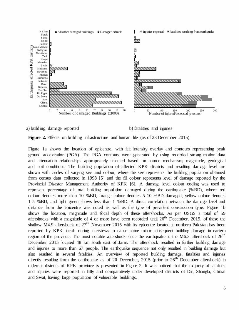
a) building damage reported
b) fatalities and injuries
Figure 2. Effects on building infrastructure and human life (as of 23 December 2015)
Figure 1a shows the location of epicentre, with felt intensity overlay and contours representing peak
ground acceleration (PGA). The PGA contours were generated by using recorded strong motion data
and attenuation relationships appropriately selected based on source mechanism, magnitude, geological
and soil conditions. The building population of affected KPK districts and resulting damage level are
shown with circles of varying size and colour, where the size represents the building population obtained
from census data collected in 1998 [5] and the fill colour represents level of damage reported by the
Provincial Disaster Management Authority of KPK [6]. A damage level colour coding was used to
represent percentage of total building population damaged during the earthquake (%BD), where red
colour denotes more than 10 %BD, orange colour denotes 5-10 %BD damaged, yellow colour denotes
1-5 %BD, and light green shows less than 1 %BD. A direct correlation between the damage level and
distance from the epicentre was noted as well as the type of prevalent construction type. Figure 1b
shows the location, magnitude and focal depth of these aftershocks. As per USGS a total of 59
aftershocks with a magnitude of 4 or more have been recorded until 26th December, 2015, of these the
shallow M4.9 aftershock of 27th November 2015 with its epicentre located in northern Pakistan has been
reported by KPK locals during interviews to cause some minor subsequent building damage in eartern
region of the province. The most notable aftershock since the earthquake is the M6.3 aftershock of 26th
December 2015 located 48 km south east of Jarm. The aftershock resulted in further building damage
and injuries to more than 67 people. The earthquake sequence not only resulted in building damage but
also resulted in several fatalities. An overview of reported building damage, fatalities and injuries
directly resulting from the earthquake as of 20 December, 2015 (prior to 26th December aftershock) in
different districts of KPK province is presented in Figure 2. It was noticed that the majority of fatalities
and injuries were reported in hilly and comparatively under developed districts of Dir, Shangla, Chitral
and Swat, having large population of vulnerable buildings.
0 2 4 6 8 10 12 14 16 18 20
Shangla
Chitral
Swat
Dir Lower
Dir Upper
Tor Ghar
Kohistan
Buner
Peshawar
Charsadda
Mardan
Nowshera
Malakand
Swabi
Mansehra
Hangu
Tank
Abbottabad
Battagram
Lakki Marwat
Haripur
Kohat
Bannu
Karak
DI Khan
Number of damaged Buildings (x1000)
Eart
hq
uake a
ffecte
d K
PK
dis
tric
ts
All other damaged buildings Damaged schools
0 50 100 150 200 250 300
Number of injured/deseased persons
Injuries reported Fatalities resulting from earthquake

7
2 Seismicity of the region
The Mountainous ranges of Himalaya, Karakoram, and Hindu Kush are amongst the most seismically
active regions in the world. The high seismicity of the region is attributed to the convergence between
the Eurasia and the India plates, with the latter slipping northwards underneath the first at a rate of 37-
48 mm/year [7]. Numerous oblique strike slip and reverse faults exist in Hindu Kush and Pamirs region,
which have resulted in moderate to severe and often to devastating earthquakes in the past [8]. Frequent
mantle earthquakes (on average five Mw 5+ earthquakes per year) occurred due to remnant lithospheric
subduction within the steeply dipping, northeast-trending tabular zone underneath the Hindu Kush
region, which is 700 km long and extends nearly to 300 km depth [9]. Other notable past damaging
earthquakes in this region include the M7.6 earthquake of 2002 centred 20 km towards the west of the
2015 earthquake, and the M7.4 earthquake of 1983 centred 8 km towards the south of the 2015
earthquake. Seismicity of northern Pakistan is attributed to north-western segment of Karakoram fault
system, whereas southern Pakistan reflects a complex plate boundary where the India plate slides
northward relative to the Eurasia plate in the east, and the Arabia plate subducts northward beneath the
Eurasia plate in far south at a rate of 17mm/year [10]. Figure 3 shows the plate boundary and epicentre
locations of all historic earthquakes with magnitude 6+ that had occurred in the region since 1900, with
notable damaging earthquakes coloured red. The data of historic earthquakes was retrieved from ANSS
Comprehensive Catalog (ComCat) [11]. The 2015 Hindu Kush earthquake was seventh earthquake of
6+ magnitude since 1970 to hit Pakistan, of these two notable recent earthquakes are 2013 Baluchistan
earthquake (Mw 7.7) and 2005 Kashmir earthquake (Mw 7.6).
Figure 3. Historical earthquakes in the region
8
7
6
Magnitude

8
a). seismograms at Nilore (II.NIL) station b) location of seismometers
Figure 4. Strong motion records and seismometer locations
The 2013 Baluchistan earthquake resulted due to oblique strike slip type motion at
shallow crustal depths (15 km) at the southern fault systems in Pakistan, with epicentre located 75 km
from Awaran. The earthquake caused at least 825 fatalities and damage to numerous rural houses [10].
The 2005 Kashmir earthquake is believed to be the most devastating earthquake to occur in the history
of Pakistan that had caused 86,000 fatalities and damage to some 600,000 buildings (including 6298
schools and 782 health facilities) [12, 13]. The earthquake occurred at a depth of 26 km and was
therefore was classified as a shallow focus earthquake. The epicentre of the earthquake was located at 19
km northeast of Muzaffarabad, resulting a shaking intensity as high as IX-X on Modified Mercalli
Intensity (MMI) scale in some densely populated areas such as Balakot and Muzaffarabad. Pakistan has
also witnessed massive destruction in 1945 due to tsunami, a result of a M8.1 earthquake centred at 100
km south of Karachi in Arabian Sea. The earthquake and associated tsunami claimed 4000 lives [14].
3 Strong motion records
It is noted that numerous seismometers have been installed throughout Pakistan to record strong motion
records (SMRs) but are of proprietary nature and were not made available to authors. The SMRs shown
in Figure 4a from two seismometers installed at Nilore (NIL) were obtained from Incorporated Research
Institutions for Seismology (IRIS) and key characteristics for 11 other stations shown in Figure 4b were
retrieved from the USGS event page. The SMR imply that the earthquake resulted from slip on a north-
trending reverse fault and resulting string motion lasted for about 50 seconds. The Hindu Kush-Pamirs
region is laced with faults, of these several have orientation similar to the fault that caused the
earthquake. However, due to uncertainties inherent in focal depth estimation the earthquake could not be
associated to a specific mapped fault.
-3%
-2%
-1%
0%
1%
2%
3%
üg /g
Eas t West0.0213 g
-3%
-2%
-1%
0%
1%
2%
3%
üg /g
North South
0.0201 g
-3%
-2%
-1%
0%
1%
2%
3%
0 50 100 150 200 250 300 350 400
üg /g
Time (s)
Vertical0.0173 g

9
a). pseudo-acceleration response spectra (ζ = 5%) b). pseudo-velocity response spectrum
Figure 5. Response spectra for the recorded strong motion data
SMRs from NIL were analysed and used to calculate pseudo-spectral acceleration values to construct a
response spectra for SMRs (see Figure 5a) along with the median and absolute maximum curve. In order
to identify the linear segments of the response spectrum, corresponding to acceleration dominated and
velocity dominated natural time period ranges, pseudo-velocity spectra was drawn for Nilore (see Figure
5b). It was observed that the response spectrum can be delineated into four main linear segments to
cover the range of natural periods of interest i.e., up to 5s. Peak ground acceleration (ügo), peak ground
velocity ( go), and spectral pseudo-acceleration values corresponding to 0.3s. 1.0s and 3.0s available
from other stations, shown in Figure 4b with circles, are given in Table 1, along with their distance from
the epicentre and name of the closest main city.
Table 1. PGA, PGV, and spectral acceleration values recorded at
City name de
(km)
ügo
(% g)
go
(cm/s)
ü0.3
(% g)
ü1.0
(% g)
ü3.0
(% g)
αa αv
Peshawar 338.8 4.61 5.85 8.02 9.88 2.08 1.7 2.6
Peshawar 340.9 7.12 9.74 18.11 17.23 3.56 2.5 2.8
Mansehra 384.2 3.82 4.7 5.33 7.79 1.66 1.4 2.6
Wah Cantt 390.5 14.13 21.71 33.4 41.26 8.26 2.4 3.0
Abbotabad 392.6 11.01 16.22 26.74 30.03 6.08 2.4 2.9
Islamabad 414.4 4.33 5.44 7 9.13 1.93 1.6 2.6
Islamabad 416.1 5.55 7.28 12.07 12.54 2.62 2.2 2.7
Islamabad 418.9 3.32 4.37 4.65 7.19 1.53 1.4 2.6
Islamabad 423.6 5.55 7.28 12.07 12.54 2.62 2.2 2.7
Rawalpindi 426.6 9.72 14.02 23.9 25.62 5.22 2.5 2.9
Islamabad 430.8 2.13 3.06 5.11 3.59 1.32 2.4 1.8
Rawalpindi 431.2 8.07 11.27 20.25 20.19 4.15 2.5 2.8
Where de = distance from epicenter; ügo = peak ground acceleration ; go = peak ground velocity; ü0.3 = spectral acceleration for
0.3s time period; ü1.0 = spectral acceleration for 1.0s time period; ü3.0 = spectral acceleration for 3.0s time period;
αa = amplification factor for acceleration dominated range; and αv = amplification factor for velocity dominated range
0%
1%
2%
3%
4%
5%
6%
7%
8%
0 1 2 3 4
5%
dam
ped
pse
udo
-acc
eler
atio
n (
g)
Natural vibration period (s)
Deep EWDeep NSSurface EWSurface NSABS MaxMedian
0.01
0.1
1
10
100
0.01 0.1 1 10 100
Pseu
do
-velo
cit
y (cm
/s)
Natural vibration period (s)
Nilore Max. Horizontal
Nilore Idealised
PGA and PGV
go
0.3
s
1.0
s
3.0
s
go

10
Figure 6. Building inventory of KPK
4 Building inventory of earthquake affected region
KPK districts closer to the Afghanistan border are not particularly economically privileged and are
comparatively under developed than other parts of central Pakistan. Figure 6 presents an overview of
housing construction types in KPK province, which is based on the census data conducted in 1998 by
Pakistan Consensus Organization [5]. It can be noted that almost 90% of the building population in KPK
has been constructed without any reinforcement. Seismic vulnerability of the building stock proliferate
due to the fact that the majority of rural buildings are poorly constructed using mud or a very weak
cement based mortar, with exception of few government and outlier type good quality buildings. Given
said that, the majority of rural buildings in the earthquake affected region of KPK can be considered
extremely vulnerable to earthquake damage, being non-engineered and built with no considerations for
seismic loading. Rural building population of KPK comprise of mostly single-storey high dwellings,
which have been constructed by unskilled house owners themselves. The following main construction
types are prevalent in KPK’s rural building stock, listed is the order of their prevalence in the region.
Unreinforced earthen (Adobe)
Unreinforced undressed stone masonry (USM)
Unreinforced brick or concrete block masonry (URM)
Confined masonry with either clay brick or concrete block (CON-URM)
Timber laced masonry and Dajji Diwari (TLM)
Urban building population of the earthquake affected region is less vulnerable than the rural building
stock and can be categorised into the following four main building typologies, also listed is the order of
their prevalence in the region.
URM buildings
Reinforced cement concrete (RCC) buildings
Steel frame (SF) buildings
CON-URM buildings
URM 35%
Adobe 32%
USM 23%
UCM 4%
TLM 2%
Misc 2%
RCC 2%
11
5 Characterisation of building diaphragms
Based on the field observations and several years of authors’ experience, the diaphragms of buildings in
the region were categorised into three main types. These types are cast in-situ rigid RC diaphragms
(CIRD), prefabricated rigid RC diaphragms (PRERD), and non-engineered flexible mud-timber
diaphragms (NEFD). CIRD vary in thickness from 100 to 150 mm and are reinforced with a single
fabricated mesh of 12 mm diameter deformed steel bars placed at an on centre spacing of 200 mm in
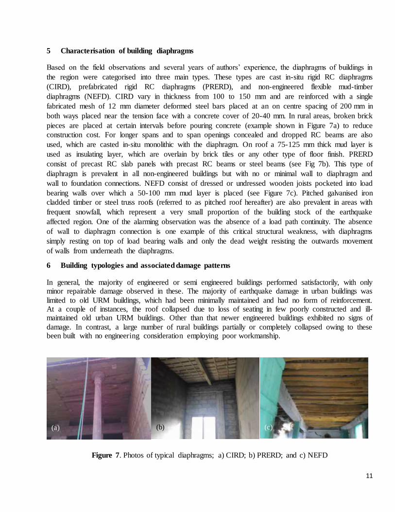
both ways placed near the tension face with a concrete cover of 20-40 mm. In rural areas, broken brick
pieces are placed at certain intervals before pouring concrete (example shown in Figure 7a) to reduce
construction cost. For longer spans and to span openings concealed and dropped RC beams are also
used, which are casted in-situ monolithic with the diaphragm. On roof a 75-125 mm thick mud layer is
used as insulating layer, which are overlain by brick tiles or any other type of floor finish. PRERD
consist of precast RC slab panels with precast RC beams or steel beams (see Fig 7b). This type of
diaphragm is prevalent in all non-engineered buildings but with no or minimal wall to diaphragm and
wall to foundation connections. NEFD consist of dressed or undressed wooden joists pocketed into load
bearing walls over which a 50-100 mm mud layer is placed (see Figure 7c). Pitched galvanised iron
cladded timber or steel truss roofs (referred to as pitched roof hereafter) are also prevalent in areas with
frequent snowfall, which represent a very small proportion of the building stock of the earthquake
affected region. One of the alarming observation was the absence of a load path continuity. The absence
of wall to diaphragm connection is one example of this critical structural weakness, with diaphragms
simply resting on top of load bearing walls and only the dead weight resisting the outwards movement
of walls from underneath the diaphragms.
6 Building typologies and associated damage patterns
In general, the majority of engineered or semi engineered buildings performed satisfactorily, with only minor repairable damage observed in these. The majority of earthquake damage in urban buildings was
limited to old URM buildings, which had been minimally maintained and had no form of reinforcement. At a couple of instances, the roof collapsed due to loss of seating in few poorly constructed and ill-maintained old urban URM buildings. Other than that newer engineered buildings exhibited no signs of
damage. In contrast, a large number of rural buildings partially or completely collapsed owing to these been built with no engineering consideration employing poor workmanship.
Figure 7. Photos of typical diaphragms; a) CIRD; b) PRERD; and c) NEFD
(a) (b) (c)

12
Figure 8. Typical observed failure modes in adobe buildings; a). reconstructed OOP collapsed boundary
wall; b). corner damage; c). evidence of pier rocking; d). vertical spandrel flexural cracking; e). vertical
crack in OOP wall; and f). OOP wall separation.
The majority of fatalities and injuries resulted due to collapse of unreinforced rural buildings and in
particular due to damaged Adobe and USM buildings. Typical characteristics of each building typology
and associated damage patterns observed during the building performance inspections undertaken
following the earthquake are discussed in the following sections. The building typologies are discussed
in ascending order of their observed seismic resistance i.e., the worst discussed first and the best
discussed last.
6.1 Adobe buildings
Adobe is arguably the oldest and the most widely used natural building material, especially in developing countries [15]. It has been a material of choice for low income rural population of Pakistan
due to its low cost, and better thermal performance but it is also extremely earthquake prone and vulnerable to collapse during an earthquake. Typical construction starts by making adobe bricks by sun
drying moulded wet mix of farm soil and straw bale, which are then laid in mud mortar to create load bearing walls. NEFD are commonly used in adobe buildings, which rest on load bearing adobe walls without any positive load path continuity or anchorage. These single storey adobe houses usually have
an isolated block of two square rooms (roughly 3 m × 3m in size), about 5 m × 5 m open yard, and a kitchen and toilet at the corner opposite to the rooms. Typical adobe wall thickness range from 200 to
600 mm, with these sitting in a very shallow trench without any foundation detail. Typical damage patterns observed in adobe buildings are shown in Figure 8 and discussed in the order
of their occurrence. Out-of-plane (OOP) collapse of boundary walls (see Figure 8a) and load bearing
(a) (b) (c)
(d) (e) (f)

13
walls was amongst the most frequent damages observed in the surveyed buildings, with the latter often resulting in partial of complete collapse of diaphragm/roof. A NEFD is used in this building typology,
which is supported by only a small bearing on the load bearing Adobe walls. At several instances, it was evident that the diaphragm collapsed due to outward movement of the supporting wall. Observed also
was extensive damage at buildings corners, which was attributed to lack of confinement at building corners. Spandrel damage in perforated in-plane loaded Adobe walls was observed at several instances, with vertical cracks initiating from opening corners and/or horizontal crack at the top end of piers (see
Figures 8c and 8d). Other less frequent observed damage patterns include vertical cracks in walls (see Figure 8e), and separation of OOP walls from perpend in-plane walls (see Figure 8f).
6.2 USM buildings
A large population of single story high USM dwellings prevails in the northern region of Pakistan,
where stone is readily available in abundance. A typical USM dwelling consists of two rooms at the rear
end of the building and a 1.5 m wide veranda, kitchen, and bath room located at the front of the house. A
flat NEFD and pitched roof are both used in USM buildings, where the latter is mainly used in areas
located up on hills expecting frequent snowfalls. The load bearing USM walls of these buildings are
constructed using mostly undressed stones irregularly laid in a cement-sand or mud mortar, with mud
mortar being more common. Sometimes, horizontal wooden planks spaced at equal vertical intervals
were also observed. The thickness of USM walls vary depending upon building location but generally
range between 300mm to 600mm. USM walls are plastered with a 30-60mm thick mud plaster on both
faces.
At numerous instances, examples of poor workmanship was also evident. In general, government USM
buildings were built to much higher quality standards using cement-sand mortar when compared to
private dwellings, which performed satisfactorily with minor damages observed. USM buildings are
extremely vulnerable to collapse during an earthquake, which has previously been witnessed during the
2005 Kashmir earthquake when numerous USM buildings collapsed and resulted in thousands of
fatalities [16].
Typical damage patterns observed in USM buildings (see Figure 9) included, OOP collapse of load
bearing walls, OOP failure of gable ends, partial OOP collapse of rock fragments, cracks near and
around openings in in-plane loaded walls and separation of OOP walls. The majority of rural USM
buildings had suffered some form of structural damage, with the majority partially or completely
collapsed. It was observed during building performance inspection surveys that poor workmanship,
absence of load path continuity i.e., absence of wall to diaphragm anchorage, and extremely low
strength of mortar used during construction had largely contributed to the large damage observed for this
type of construction. USM buildings constructed of dressed stones and cement-based binder performed
better than undressed USM, with these undergoing only localised minor OOP damage in gable ends and
cracking in narrow piers.

14
Figure 9. Typical observed failure modes in USM buildings; a) roof collapse due to OOP wall failure ;
b) diagonally cracked USM wall at the verge of OOP collapse, which was possibly due to combined in-
plane and out of plane loading; c) partially collapsed OOP wall still supporting roof ; d) OOP failure of
USM wall with intact pitched roof; e) localised OOP collapse of rock fragments; f) extensive in-plane
diagonal shear cracks in squat USM wall; g) diagonal shear cracking in perforated USM wall; g) gable
end damage in good quality USM buildings; and f) vertical crack due to differential ground settlement.
6.3 URM buildings
URM buildings are by far the most common typology in both urban and rural areas of Pakistan, which
are typically one to three story high. Burnt clay bricks, being 75 × 115 × 225 mm with a compressive
strength of about 5-10 MPa, are laid following an English bond pattern using a cement-sand mortar with
a volumetric mix ratio of 1:3. Thickness of load bearing URM walls is typically a multiple of one brick
width (also referred to as wythe). Two wythe (220 mm) thick and three wythe (330 mm) thick URM
walls are typically used for load bearing walls and one wythe thick URM walls are used as non-
(a) (b) (c)
(d) (e) (f)
(g) (h) (i)

15
structural partition walls. Typically, a 12-25 mm thick cement-sand (1:6) plaster is also applied over
both faces of URM walls to create smooth surface for consecutive painting. The thickness of URM walls
is doubled at its base in steps, with each step being one course high and half brick length wider than the
step above. URM walls with this stepped detail are founded on a 50 mm thick layer of levelling concrete
strip overlying compacted earth at a depth of 1-2 m below natural surface level. Urban and rural URM
buildings were distinctly different in their structural form. As a general trend, CIRD was used in urban
URM buildings and NEFD was the mostly adopted roof in rural URM buildings. As discussed earlier,
damage in URM buildings was mainly observed in old URM buildings of significant age.
Figure 10. Performance of URM buildings; a). OOP collapsed URM boundary wall; b). extensive
diagonal cracks through bricks in old URM college building located in Swat; c). spandrel shear cracking
and pounding damage in old URM building with lime based mortar; d-f). spandrel damage and cracking
around window openings in old URM buildings; g). OOP deflected wall in a rural URM building; h).
veneer collapsed out of plane; and i). undamaged URM building with severely damaged USM part.
(a) (b) (c)
(d) (e) (f)
(g) (h) (i)
16
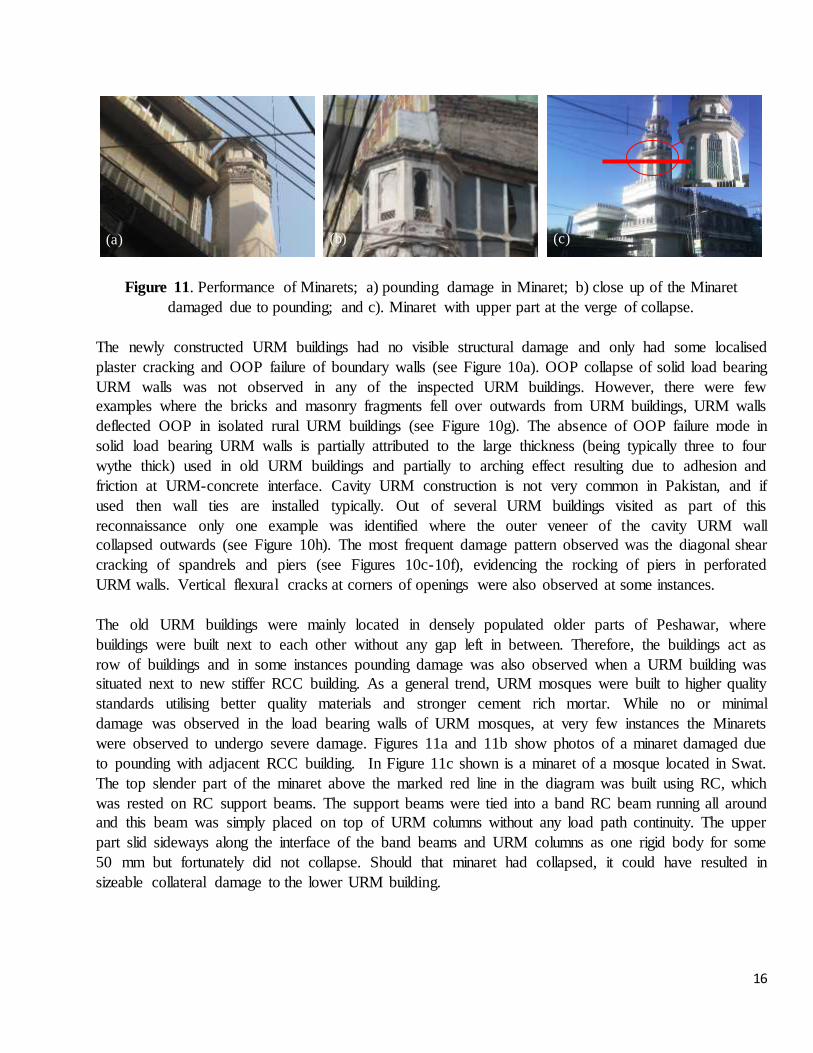
Figure 11. Performance of Minarets; a) pounding damage in Minaret; b) close up of the Minaret
damaged due to pounding; and c). Minaret with upper part at the verge of collapse.
The newly constructed URM buildings had no visible structural damage and only had some localised
plaster cracking and OOP failure of boundary walls (see Figure 10a). OOP collapse of solid load bearing
URM walls was not observed in any of the inspected URM buildings. However, there were few
examples where the bricks and masonry fragments fell over outwards from URM buildings, URM walls
deflected OOP in isolated rural URM buildings (see Figure 10g). The absence of OOP failure mode in
solid load bearing URM walls is partially attributed to the large thickness (being typically three to four
wythe thick) used in old URM buildings and partially to arching effect resulting due to adhesion and
friction at URM-concrete interface. Cavity URM construction is not very common in Pakistan, and if
used then wall ties are installed typically. Out of several URM buildings visited as part of this
reconnaissance only one example was identified where the outer veneer of the cavity URM wall
collapsed outwards (see Figure 10h). The most frequent damage pattern observed was the diagonal shear
cracking of spandrels and piers (see Figures 10c-10f), evidencing the rocking of piers in perforated
URM walls. Vertical flexural cracks at corners of openings were also observed at some instances.
The old URM buildings were mainly located in densely populated older parts of Peshawar, where
buildings were built next to each other without any gap left in between. Therefore, the buildings act as
row of buildings and in some instances pounding damage was also observed when a URM building was
situated next to new stiffer RCC building. As a general trend, URM mosques were built to higher quality
standards utilising better quality materials and stronger cement rich mortar. While no or minimal
damage was observed in the load bearing walls of URM mosques, at very few instances the Minarets
were observed to undergo severe damage. Figures 11a and 11b show photos of a minaret damaged due
to pounding with adjacent RCC building. In Figure 11c shown is a minaret of a mosque located in Swat.
The top slender part of the minaret above the marked red line in the diagram was built using RC, which
was rested on RC support beams. The support beams were tied into a band RC beam running all around
and this beam was simply placed on top of URM columns without any load path continuity. The upper
part slid sideways along the interface of the band beams and URM columns as one rigid body for some
50 mm but fortunately did not collapse. Should that minaret had collapsed, it could have resulted in
sizeable collateral damage to the lower URM building.
(a) (b) (c)

17
6.4 UCM buildings
UCM building construction is a relatively new in Pakistan compared to URM and USM but is gaining
wider acceptance in both urban and rural areas of Pakistan. UCM construction is perceived as more
economical and faster than URM due to its bigger size and more uniform strength characteristics. In
rural areas, low strength locally made solid concrete blocks are used, having a size of 150 × 200 × 300
mm and a compressive strength of 5-8 MPa. UCM buildings are typically single story high in rural areas
and up to two story and rarely three story high in urban areas. The concrete blocks are laid in staggered
stack bond pattern using a cement-sand mortar, with typical volumetric mix ratio of 1:3 or 1:6 in urban
areas and 1:8 in rural areas. The UCM walls were mostly not plastered, with fewer exceptions where a
mud or cement-sand plaster was used to render both faces of the wall. UCM walls usually rest on
roughly 600 mm wide RC strip foundation constructed using concrete with volumetric mix ratio of 1:2:4
(cement:sand:aggregate), with a layer of underlying lean concrete laid over compacted earth.
Typical damage patterns observed in rural UCM buildings built using mud were out of plane failure of
walls, collapse of roof due to loss of seating, diagonal shear cracking, cracks near openings, corners
failures, and vertical cracks in walls. UCM built using mud was quite common in Federally
Administered Tribal Areas (FATA) however rural buildings built with a cement mortar performed better
with no to minimal damage.
Figure 12. Some examples of damaged rural UCM buildings: a). photo of a rural UCM house; b).
example of out-of-plane failure; c). example of diagonal cracking; d). example of vertical cracking in
piers, where blocks were not staggered; e). extensive in-plane damage to UCM wall; and f). example of
vertical crack where blocks were not staggered.
(a) (b) (c)
(d) (e) (f)

18
Figure 13. Photo of TLM building located in Peshawar
6.5 TLM buildings
TLM is similar to a local traditional timber construction type called Daji Diwari (DD). TLM has been
rarely used in side walls of old buildings located in the older parts of Peshawar city, which consisted of
vertical timber studs roughly spaced every 900 mm and equally spaced horizontal timber blockings
creating box like openings that had been in-filled with URM (see Figure 13a). Whilst DD has mostly
been used in northern hilly areas of Pakistan (i.e., Chitral and Kashmir) where stone and timber both are
locally available in abundance. The use of DD is not common in earthquake affected region of KPK,
with Chitral being the only KPK district where this building typology prevail. A typical DD wall is
constructed by first constructing diagonally braced timber frames on top of USM foundation, which are
then in-filled with undressed stones laid in mud or cement-sand mortar as a binding material for acoustic
and thermal insulation. Timber frames of DD are connected to the USM foundation using nuts and
mechanical anchor bolts. The constructed DD walls are then plastered on both faces using mud mortar.
Hand sawn timber floor boards resting over timber joists are used as floors and a pitched roof. Many DD
buildings also have a flat NEFD. A recent experimental study [17] investigated seismic performance of
DD buildings, which suggested that DD buildings are capable of sustaining substantially large
earthquake forces. USM infill was observed to increase the energy dissipation capacity of the system but
had minimal contribution towards the lateral load capacity of the structure. Authors did not visit the
areas with DD building population but news reports and residents of that area suggest that DD buildings
had generally performed well during the earthquake.
6.6 CON-URM Buildings
This building typology was prevalent in both urban and rural areas of Pakistan in relatively new one to
three storey high buildings. Typically, a continuous minimally RC strip foundations running under all
masonry walls are used in CON-URM buildings. Minimal reinforcement for confining vertical members
stems from the same foundation strip and is left until the masonry walls are constructed around these.
Masonry units (either concrete blocks or clay bricks) create teething at locations where confining
vertical RC members would be built at a later stage. The left space is then minimally reinforced with
deformed steels bars and concrete is casted in-situ using a concrete mix with volumetric ratio of 1:2:4
(cement:sand:aggregate) with no fixed w/c ratio that yield in a concrete compressive strength of 15-30
MPa. Afterwards RC horizontal confining elements (often referred to as band beams) and a CIRD are
concurrently constructed. The same procedure is repeated for constructing upper storeys.

19
Figure 14. Photos of un-damaged CON-URM buildings: a). rural single storey CON-URM building;
b). rural CON-URM mosque; and c). under construction CON-URM house.
CON-URM buildings generally performed better than URM buildings, with no or minimal damage
observed in any of these buildings. The damage was limited to few cracks at several instances. Photos of
typical CON-URM buildings are shown in Figure 14.
6.7 RCC buildings
RCC construction has been used in buildings with four or more storeys for last few decades, with pre-
1970 RCC buildings mainly relying on a RCC frame structure designed to take gravity loading only.
The majority of these RCC buildings lack seismic detailing and can be categorised as earthquake-prone.
The design and construction practices evolved over time and most of the recently constructed structures
have been built with some form of earthquake resisting lateral load resisting system. The majority of
RCC buildings in earthquake affected areas have been constructed after 1990, with these being mostly
used to construct four and more story buildings in urban areas. Provision of shear walls is not common
in buildings built prior to 2005, when the 2005 Kashmir earthquake resulted in damage to a large
number of RCC frame buildings and major changes were adopted in response to lessons learnt in
Pakistan Building Code [18] and overall in civil engineering practice . This can be marked as a major
shift in RCC design and construction practices.
RCC building stock in earthquake affected areas can be categorised into three main types, being non-
engineered, semi-engineered, and engineered. Non-engineered RCC buildings are mainly low-rise up to
three story height and are typically construed relying on experience of non-qualified building
practitioners. These buildings often contain design defects, and low quality of construction. Semi-
engineered RCC buildings have some form of design calculations and minimal quality control, typically
design drawings and specifications are developed but employing minimal engineering consideration.
The buildings, often lack in seismic detailing and may contain some design/construction defects. The
majority of pre-2005 RCC buildings also lies in this category because many high seismic risk regions
were given a relatively lower seismic rating in Pakistan building code of that time [19]. The concrete
compressive strength ranges from 20-35 MPa in non-engineered or semi engineered RCC buildings,
with no or minimal quality control. Whilst engineered RCC construction is typically designed and
supervised by qualified engineering professionals and mostly comply with international standards.
(a) (b) (c)

20
A typical under construction engineered RCC building with dual load resisting system is shown in
Figure 15a, whereas a semi-engineered RCC frame building is shown in Figure 15b. In this section, the
discussion is limited to non-engineered and semi-engineered RCC construction because engineered RCC
construction does not follow specific trends and most of the times are unique in terms structural
characteristics. Lateral load resisting system of these RCC buildings mainly consisted of RCC moment
frames with non-structural brick masonry or concrete block masonry infill panels. In almost all RCC
buildings, a CIRD has been used. Partition walls are one wythe (115 mm) thick URM or UCM walls
with a thickness of 150-200 mm, without any anchorage with the diaphragms. The infill masonry panels
in modern engineered RCC buildings are constructed by leaving a gap around the panel, with panel tied
to column using mild steel plates bent casted with one end embedded in concrete column and
straightened afterwards to align with bend joints in infill masonry panels. Deformed reinforcement steel
bars are locally available in two main grades, being Grade 40 (with a nominally specified yield strength,
fy = 275 MPa) and Grade 60 (with fy = 415 MPa). The Grade 40 steel bars are used in the construction of
CIRD, whereas the Grade 60 steel bars are used to construct foundations and frame members. Typical
story height in RCC buildings is 3.0 - 3.7 m. The foundation are designed to carry the anticipated
loading and the use of isolated column footing with tie beams or a mat foundation both are common.
Figure 15. Photos of RCC buildings after the earthquake: a). under construction engineered RCC
building; b). semi-engineered RCC frame building; c). infill-frame interface damage in non-engineered
RCC building; d). infill- frame interface damage in semi-engineered RCC building; e). diagonal crack in
perforated infill masonry wall; and f). damage at seismic joint location.
(a) (b) (c)
(d) (e) (f)

21
Figure 16. Interior of an industrial steel building located in Hattar industrial zone
In low-rise RCC buildings, columns are often constructed to flush with infill masonry wall and therefore
column width is often equal to the thickness of infill masonry panel, being 200 mm for UCM and 220
mm for URM. This result in a rectangular column, with typical column length of 400-600 mm.
However, the majority of newly constructed buildings had square columns having a width of 375-600
mm. RCC beams are mostly rectangular in shape having a width of 200-400 mm and depth ranging from
300 to 600 mm.
The new RCC buildings with four and more storeys are mostly engineered and often consist of a dual
lateral load resisting system, being seismically detailed RCC frame supplemented by RCC shear walls
(dual). Amongst typical damage patterns were damage at infill masonry panel-column interface (Figure
15c and 15d) diagonal shear cracking in infilled masonry panels, diagonal cracks near opening corners
when a perforated infill masonry panel was used (Figure 15e), minor diagonal shear cracks in the
masonry infill panels, and with very few column failure examples. By far cracking at the interface of
panel and surrounding frame was the most commonly observed damage pattern. At some instances,
damage at seismic joint location was also observe din modern row type RCC buildings (se Figure 15f).
6.8 SF buildings
Steel construction is not very common in Pakistan and only few shed type industrial buildings were
observed in mainly the industrial zones like Hattar. These buildings can be classed semi-engineered and
typically have a galvanised iron sheet cladded roof, with sheets resting over purlins connected to hot
rolled steel trusses or portal frames. Welded connections are common. These buildings are mostly single
storey, with large spans and storey height. Typically, 1-1.5 m high reinforced concrete masonry walls
resting on RCC foundation strip are built on exterior periphery with GI cladding in upper part of exterior
walls. An interior view of a typical industrial steel building is shown in Figure 16. No damage has been
reported or observed in steel buildings.
7 Concluding remarks
An overview of observations made on the 2015 Hindu Kush Earthquake and the subsequent aftershock
series was presented, which includes an account of seismotectonics, strong motion characteristics, and
the seismicity of the region. The resulting damaging effects on human life and building infrastructure

22
was quantitatively commented on by interrogating the statistical data collected as part of disaster
management activities. To assess the performance of different types of buildings a reconnaissance was
undertaken soon after the main earthquake. The survey was carried out in the majority of affected
regions of KPK. It was observed that the majority of fatalities and injuries occurred primarily due to
collapsed rural unreinforced single storey houses, constructed by local un-experienced masons using
locally available materials such as stone, adobe, clay bricks and low strength concrete blocks. The large
portion of the damaged houses, mostly constructed using rubble masonry laid in mud mortar, were
situated on the slopes of mountains/hills at high altitude of the northern region of Pakistan accessible
only by walk. It was observed during building performance inspections that despite of loss of lives and
massive destruction of houses, the same material and construction techniques were being used by locals
for reconstruction of houses because of winter arrival and economic condition of the locals. While the
provincial and national disaster management authorities of Pakistan are very active in response and
recovery efforts, there still are challenges to overcome resource challenges. A large campaign (door to
door) needs to be initiated by local authorities to assess the houses of low income families, specially
living in the hilly areas. A program to educate local building owners and non-qualified builders about
low cost techniques for repairing/seismic improvement of existing vulnerable houses, and about basic
seismic safety provisions for simple local type structures would also help reduce future risk of
experiencing similar or perhaps more severe consequences that could result from a shallow earthquake
in the region. The following are some key findings of the study.
The perceived shaking intensity in Pakistan was reported to be moderate-strong based but the
damage level observed was between strong to very strong, being much larger than expected for
such instrumented shake intensity.
Partial or complete collapse of buildings was mostly observed for non-engineered rural building
stock and in some cases in old urban URM buildings.
The findings from interrogation of damage statistics, damage assessment surveys, and interviews
with building practitioners and occupants of earthquake damaged houses suggested that the
majority of the detrimental effects on human life and building infrastructure were associated to
partial or complete collapse of vulnerable buildings.
At several instances, building components were at the verge of collapse or were extensively
damaged suggesting substantially reduced residual strength thus posing significant seismic
hazard to their occupants and/or users. The local building control authorities may consider
earthquake had no tagging restriction on use by as earthquake/aftershock of same magnitude is
expected to occur in the nearby future and may collapse these buildings.
The semi-engineered (confined masonry) performed satisfactorily compared to completely
unreinforced building stock. Authors believe that more research is warranted to develop seismic
resistant details suitable for local use, considering the socio-economic situation of the areas.
One of the key observations on masonry infilled RCC framed buildings was the frequently
noticed damage at the interface of infills and surrounding frame. At several other instances shear
damage in non-structural masonry infills was also observed. A substantial amount of research

23
has be undertaken on minimising such damage and inclusion of such literature in civil
engineering curricula would be advantageous.
The damage statistics shows that a large number of remotely located schools have also been
damaged, with extent of damage not known to authors. If the damage is of structural nature and
then the residual strength of these buildings may have been compromised. These school
buildings should be assessed as priority by competent engineers and should the need arise
restriction on their use be enforced. Attempts should be made at government level to evaluate
these buildings in detail to identify risk of future collapse.
Finally, Authors believe that there is a need of more collaboration between local and as well as
international stake holders i.e. practicing engineers, academics, and other involved in studying
and reporting earthquakes. Even though a large number of seismometers have been installed as
part of Pakistan, yet recorded data is not made available to wider community of engineers and
academic for further analysis and research.
8 References
1. USGS. Event page: M7.5 - 45km E of Farkhar, Afghanistan. 2015 [cited; Available from: http://earthquake.usgs.gov/earthquakes/eventpage/us10003re5#general_summary.
2. PMD. Latest earthquake reports. 2015 [cited 2015 19 Dec.]; Available from:
http://www.pmdnmcc.net/seismic/latestearthquakes.asp.
3. ARG. 115 killed, 538 injured; 7,630 homes, 12 schools, 17 mosques, 20 office buildings have been damaged in 9 provinces. 2015 [cited 2015 27 October]; Available from:
www.president.gov.af.
4. Worden, C. B., Gerstenberger, M. C., Rhoades, D. A., and Wald, D. J., Probabilistic relationships between ground-motion parameters and Modified Mercalli intensity in California. Bulletin of the Seismological Society of America, 2012. 102(1): p. 204-221.
5. PBS. Population census data, Khyber Pakhtunkhwa district at a glance. 1998 [cited 2015 12 Dec. 2015]; Available from: http://www.pbs.gov.pk/pco-kpk-tables.
6. PMDA, Report of damages due to 26th October, 2015 Earthquake. 2015, Provincial Disaster Management Authority, Government of Khyber Pakhtunkhwa: Peshawar, Pakistan.
7. USGS. Event page: magnitude 7.6 - Pakistan. 2005 [cited; Available from:
http://earthquake.usgs.gov/earthquakes/eqinthenews/2005/usdyae/.
8. Chmyriov, V.M. and S.H. Mirzad, Geologic map of Afghanistan. 1972, Department of Geology and Mines, Ministry of Mines and Industries of Royal Afghanistan: Kabul, Afghanistan.
9. Wheeler, R. L., Bufe, C. G., Johnson, M. L., and Dart, R. L., Seismotectonic map of Afghanistan
with anotated bibliography 2005, US Geological Survey: Reston, USA.
10. USGS. Event page: M7.7 - 61km NNE of Awaran, Pakistan. 2013 [cited 2015 22 Dec.]; Available from:
http://earthquake.usgs.gov/earthquakes/eventpage/usb000jyiv#general_summary.

24
11. USGS. ANSS Comprehensive Catalog and Important Caveats. 2015 [cited 2015 22 Dec.]; Available from: http://earthquake.usgs.gov/earthquakes/map/doc_aboutdata.php.
12. Bothara, J.K. and K.M.O. Hiçyılmaz, General observations of building behaviour during the 8th
October 2005 Pakistan earthquake. Bulletin of the New Zealand Society for Earthquake Engineering, 2008. 41(4): p. 209-233.
13. ERRA, Strategy document rural housing construction, building back better: rural housing
reconstruction strategy of Earthquake hit districts in NWFP and AJK. 2006, Earthquake Reconstruction and Rehabilitation Authority: Islamabad, Pakistan.
14. DAWN. 1945: Tsunami strikes Karachi coast, killing 4,000. 2014 [cited 2015 22 Dec.];
Available from: http://www.dawn.com/news/1131310.
15. Houben, H., Guillard, H, Earth Construction: a Comprehensive Guide. Practical Action, London (1994). 1994, London: Practical Action.
16. Naseer A., N.A., Hussain Z., and Ali Q, Observed Seismic Behavior of Buildings in Northern
Pakistan during the 2005 Kashmir Earthquake. Earthquake Spectra, 2010: p. 425-449.
17. Ali, Q., Schacher, T., Ashraf, M., Alam, B., Naeem, A., Ahmad, N., and Umar, M., In-plane behavior of the Dhajji-Dewari structural system (wooden braced frame with masonry infill). Earthquake Spectra, 2012. 28(3): p. 835-858.
18. MOHW, Building code of Pakistan 1986. 1986, Ministry of Housing and Works, Government of
Pakistan: Islamabad, Pakistan.
19. MOHW, Building code of Pakistan (seismic provisions - 2007). 2007, Ministry of Housing and Works, Government of Pakistan: Islamabad, Pakistan.