reconfigurable systems for cryptography and...
TRANSCRIPT

Chapter 1
© 2012 Majzoub and Diab, licensee InTech. This is an open access chapter distributed under the terms of the Creative Commons Attribution License (http://creativecommons.org/licenses/by/3.0), which permits unrestricted use, distribution, and reproduction in any medium, provided the original work is properly cited.
Reconfigurable Systems for Cryptography and Multimedia Applications
Sohaib Majzoub and Hassan Diab
Additional information is available at the end of the chapter
http://dx.doi.org/10.5772/10.5772/30186
1. Introduction The area of reconfigurable computing has received considerable interest in both its forms: fine-grained (represented in FPGA) and coarse-grained architectures. Both architecture styles attempt to combine two of the important traits of General Purpose Processors (GPPs) and Application-Specific Integrated Circuits (ASICs): flexibility and speed (Hartenstein, 2001). It provides performance close to application-specific hardware and yet preserves, to a certain degree, the flexibility of general-purpose processors. In this chapter, we explore, evaluate, and analyze the performance of a reconfigurable hardware, namely MorphoSys, considering certain key applications targeted for such hardware (Hauck, 1998).
MorphoSys is a reconfigurable architecture designed for multimedia applications, digital signal and image processing, cryptographic algorithms, and networking protocols (Singh et al., 1998). In this chapter, we discuss application mapping, identify potential limitations and key improvements and compare the results with other reconfigurable, GPP, and ASIC architectures. In cryptography, we present the mapping and performance analysis of the Advanced Encryption Standard, namely Rijndael, (Daemen & Rijmen, 2002), along with another cryptography algorithm, namely Twofish, (Schneier et al., 1998). In image processing, we present linear filtering, and 2D and 3D computer graphics algorithms, (Diab & Majzoub, 2003), (Damaj et al, 2002). We present the mapping with detailed analysis, highlighting bottlenecks, proposing possible improvements, and comparing the results to other types of multimedia processing architectures (Maestre et al., 1999), (Mei et al, 2003), (Tessier & Burleson, 2001).
2. Reconfigurable computing
General-purpose processor (GPP) is a confined hardware system that computes any task using existing instructions and registers. Thus, GPP is used to compute diverse range of

Data Acquisition Applications 4
applications. Application-Specific Integrated Circuits (ASIC), on the other hand, are used to implement a single fixed function. Therefore, ASICs have no flexibility and they can only execute a very limited type of the targeted applications known beforehand (Singh et al., 1998), (Kozyrakis, 1998), (Möller et al., 2006).
Combining the two main traits of the two design styles, namely GPPs and ASICs, reconfigurable systems stand halfway between traditional computing systems and application specific hardware (Kozyrakis & Patterson, 1998). Thus, reconfigurable hardware is a name referred to a system that can be reconfigured and customized in post-fabrication to execute a specific algorithm. MorphoSys, with its customizable logic and routing resources, can be configured, and customized during runtime. This feature provides the ability to compute a wide variety of applications. It shares characteristics of microprocessors, it can be programmed in post-fabrication, and of specific hardware, it can employ a specific algorithm or function to gain the speed (Hartenstein, 2001), (Ferrandi et al, 2005).
Reconfigurable computing is the hardware capability to adapt, configure, and customize itself to provide the best performance for a specific application. It is shifting some of the software complexity to the hardware itself. Fine-grain reconfigurable platforms have bitwise reconfigurable logic, for instance FPGAs. Coarse-grain reconfigurable platforms have more than one bit granularity. Coarse-grain reconfigurable platforms have the advantage of less power consumption and area over the fine-grain at expense of lower flexibility (Galanis et al, 2004), (Eguro & Hauck, 2003). For the multimedia applications, the foreseen potential of the reconfigurable computing in general and coarse-grain reconfigurable platforms in particular is well recognized. The goal of reconfigurable platforms, whether fine-grain or coarse-grain, is to provide high performance, close to ASIC and high flexibility close to general-purpose processors. As such, reconfigurable computing is seen as a major shift in the processor design and research (Hartenstein, 2001).
The parallelism feature of most of the coarse-grain platforms adds a distinctive yet essential advantage to such hardware. Recent work in mesh-based coarse-grain reconfigurable architectures includes GARP (UC Berkeley) (Hauser & Wawrzynek, 1997), MATRIX (CalTech) (Mirsky & DeHon, 1996), REMARC (Stanford) (Miyamori & Olukotun, 1998), and MorphoSys (UC Irvine) (Singh et al., 1998).
In view of all that, performance and hardware analysis should be investigated to identify all the bottlenecks and provide a realistic feedback in order to propose future improvements. Targeted applications, such as multimedia, cryptographic, and communication, should be mapped to determine the hardware behaviour. The analysis is intended to provide feedback on the hardware capability and highlight potential modifications and enhancements (Bosi, Bois, & Savaria, 1999). Unfortunately, most of the coarse-grain reconfigurable platforms, except the FPGA based platforms, lack-easy-to-use compiler and mapping tools to map such applications on the hardware under examination. Therefore, the mapping of the targeted applications for such hardware evaluation must be carried out manually. This hand-mapping process can provide valuable information to prospective compilers that eventually

Reconfigurable Systems for Cryptography and Multimedia Applications 5
will emerge out of the implementation of wide range of applications (Majzoub & Diab, 2003), (Majzoub & Diab, 2006), (Majzoub et al, 2006), (Itani & Diab, 2004),(Bagherzadeh, Kamalizad & Koohi, 2003).
3. MorphoSys design
MorphoSys is one of the few coarse-grain reconfigurable platforms. Fig. 1 shows the block diagram and internal structure of MorphoSys M1 chip and the logic block for each reconfigurable cell. MorphoSys consists of two main blocks: a RISC processor, TinyRISC, and the Reconfigurable Cell (RC) Array. The other supporting blocks are: the RC context memory, the frame buffer, and the DMA controller. The frame buffer as well as the context memory provides the data and instructions, respectively, in parallel fashion to the RC Array (Lee et al., 2000).
The computing power of the MorphoSys hardware lies in the reconfigurable device. It is divided into four quadrants. Fig. 2 shows the internal interconnectivity of the RC system (Lee et al., 2000). As shown, three hierarchical levels define the interconnection meshwork. The first is a layer that connects each cell to its adjacent cell, i.e. upper, lower, and left cells. The second is an intra-quadrant connection that connects the RCs in the same row or column within the same quadrant. The third level of connectivity is an inter-quadrant connection that links any two cells in different quadrant but in the same column or in the same row. Fig. 1 also shows the RC block diagram. It consists of multiplexers, ALU, four registers, variable shifter, and output register. The inputs for every RC are from the frame buffer, other RCs, and internal Registers (Singh et al., 1998).
Figure 1. MorphoSys Block Diagram and RC Logic Digaram

Data Acquisition Applications 6
Figure 2. RC Array Communication Buses
4. Cryptographic algorithms mapping onto MorphoSys
Cryptography has grown to be a fundamental element to handle authenticity, integrity, confidentiality and non-reputability of private data flows through public networks. With the increasing demand for high performance hardware, and high level of security, better ciphers are making their way to replace aging algorithms that have proven to be too weak or too slow for the current applications (Schneier, 1996). In this section, we discuss the mapping of the Rijndeal and Twofish encryption algorithms.
4.1. Rijndael encryption algorithm
The Advanced Encryption Standard, AES, is a block cipher adopted as an encryption standard by the National Institute of Standards and Technology, NIST, in November 2001 after a five-year standardization process. The block diagram of the Rijndael algorithm is shown in Fig. 3. The figure shows the steps for both encryption and decryption cases (Daemen & Rijmen, 2002).
4.1.1. Rijndael rounds
First, the input bits are arranged according to the length of the plain text to be encrypted. In the case of 128 bit length, the bits are arranged as 44 matrix of bytes; for 192, it will be 46 matrix of bytes; and for 256, it will be 48 matrix of bytes. The numbers 4, 6, and 8 are called the block width, Nb. The keys of the cipher are also arranged in the same fashion (Daemen & Rijmen, 2002).
Rijndael has three different types of Rounds; as shown in Fig. 3:
i. The first is the Initial Round. It is, as shown in equation (1), performed by XORing the input Plain Text matrix with a predefined Key. This process called Add-Round-Key.

Reconfigurable Systems for Cryptography and Multimedia Applications 7
B A K (1)
where B (size 4 by Nb) is the output byte matrix, A (size 4 by Nb) is the input byte matrix and K (size 4 by Nb) is the Key byte matrix.
Figure 3. The Rijndael Algorithm (Daemen & Rijmen, 2002).
ii. The second is the Standard Round. In the Standard Round four different steps are performed:
a. Sub-Bytes: this is a simple byte substitution using a predefined lookup table. Two tables are used, one for encryption and another for decryption.
b. Shift-Row: this step is performed through shifting and rotating the bytes in each row of the input matrix in a predefined manner. The shifting offset is defined according to the block width Nb. The bytes will be shifted, then, rotated repeatedly.
c. Mix-Column: the columns are mixed through a matrix multiplication of the plain text by a predefined matrix, given by the authors of the Rijndael algorithm (Daemen & Rijmen, 2002), over Galois Field with an irreducible polynomial 100011011. In the decryption case, this step is referred to as Inverse Mix-Column or InvMix-Column.
Some mathematical simplification is carried out in order to reduce the multiplication computation. In the encryption case the multiplication is performed as shown in equation (2). Note that the multiplication operator is shown as to indicate that the multiplication is over Galois Field (Daemen & Rijmen, 2002).

Data Acquisition Applications 8
00 07 00 07
10 17 10 17
20 27 20 27
30 37 30 37
02 03 01 0101 02 03 0101 01 02 0303 01 01 02
B B A AB B A AB B A AB B A A
(2)
The matrix used in the multiplication during the Inverse Mix-Column (InvMix-Column) step is shown in equation (3). This multiplication is also carried over Galois Field with the irreducible polynomial 100011011 (Daemen & Rijmen, 2002).
00 07 00 07
10 17 10 17
20 27 20 27
30 37 30 37
0 0 0 0909 0 0 00 09 0 00 0 09 0
B B A AE B DB B A AE B DB B A AD E BB B A AB D E
(3)
a. Add-Round-key: is XORing each byte with a predefined key.
Rijndael has a variable number of iterations, Ni, for the Standard Round:
Ni = 9, where Nr = Number of rounds = 10, if both the block and the key are 128 bits long. Ni = 11, where Nr = 12, if either the block or the key is 192 bits long, and neither of them
is longer than that. Ni = 13, where Nr = 14, if either the block or the key is 256 bits long.
Table 1. shows the key size, block width Nb and the corresponding Nr.
Key Size 128 192 256
Nb 4 6 8 Nr 9 11 13
Table 1. Key Size, Block Width Nb and Round Number Nr, (Daemen & Rijmen, 2002)
i. The third type of round is called the Final Round. In the Final Round only three of the four steps, mentioned in the Standard Round, are performed excluding the Mix-Column step.
During decryption, all the steps are preformed in reversed order (Daemen & Rijmen, 2002).
4.1.2. The key schedule for Rijndael
The Round-Keys are derived from the original Cipher Key by means of the Key Schedule. The algorithm to generate the key is shown in Fig. 4. The original key provided is 128, 192 or 256 bits. The key should be arranged in a 4Nb Matrix. As discussed in the previous section, the Add-Round-Key step is performed once in the First Round, Nr-1 times in the Standard Round, and once again in the Final Round. In total, Nr+1 Round-Key matrices are needed to cover all the rounds.

Reconfigurable Systems for Cryptography and Multimedia Applications 9
The first Round-Key is given, as shown in equation (4), however, the remaining, Nr, Round-Key matrices are generated (Daemen & Rijmen, 2002). For example, for a block length of 128 bits, 10 Round-Keys matrices are needed: 9 for the Standard Rounds and 1 for the Final Round. For block length of 192 bits, 12 Round-Keys are needed and for 256 bits length 14 are needed.
0 1 0 100 00
1 1 1 110 100 1
20 202 1 2 1
30 303 1 3 1
;
b b
b b
bb b
b b
N N
N NN
N N
N N
k kk kk kk k
K K Kk kk kk kk k
(4)
Figure 4. Generating key schedule for Rijndael (Daemen & Rijmen, 2002).
Then the remaining keys are generated (Daemen & Rijmen, 2002). Fig. 4 shows the key schedule algorithm, where i denotes the column number, iterating from 0 to Nb-1. The function S1(Ki-1) is a cyclic shift of the elements in Ki-1. For example, if Ki-1 column is [k0x, k1x, k2x, k3x], then S1(Ki-1) is [k1x, k2x, k3x, k0x].
The rcon function is a round-dependent constant XORed to the first byte of each column (Daemen & Rijmen, 2002). These round constants are calculated offline. It is the successive powers of 2 in the representation of GF(2^8) (Daemen & Rijmen, 2002). The Key is saved in the memory to be XORed during the encryption or decryption.
4.1.3. Rijndeal performance analysis
In this section, the performance results are presented. Some of the bottleneck problems are discussed, and possible solutions are proposed (Majzoub et al., 2006). Fig. 5(a) shows the time cost of the four steps done in one iteration of the Standard Round. The figure shows the

Data Acquisition Applications 10
encryption and the decryption costs for all the key length cases. Clearly, the Sub-Bytes step, or the lookup table step, is dominating the computation time. The Sub-Bytes step is taking 83% of the total Round cost in the best case and 97% in the worst case. The next bottleneck is the Mix-Column and InvMix-Column step. Both InvMix-Column and Mix-Column steps are taking 2% in the best case and 16% in the worst case.
(a) (b)
Figure 5. Time cost breakdown, (a) Encryption and Decryption, and (b) Inverse-Key (Inv-Key) Schedule.
Fig. 5(b) shows the time cost of the Inverse Key Schedule performance results. Again, the Sub-Bytes and the InvMix-Column are the major bottlenecks. The Sub-Bytes is taking 60% in the best case and 74% in the worst case. The InvMix-Column is taking 22% in the best case and 35% in the worst case.
Fig. 6 shows the RC Utilization during the encryption and decryption respectively. The figure shows the RC utilization for one iteration of the Standard Round. It is clear the 8×8 RC Array is fully utilized during the lookup table and partially utilized, but with high rate, during the Mix-Column and InvMix-Column.
As shown in Fig. 6, there are 4 lookups in case of 256 covering the 4 rows. In the 192 case, there are 3 lookups to cover the 3 rows and in the case of 128 there are 2. During every lookup there is a full utilization and then a small stall when switching from one row to another. At the end of lookup step, the Mix-Column step starts. The Mix-Column utilizes half the RC Array in the 192 and 256 cases and quarter of the RC Array in the 128 case. The InvMix-Column almost utilizes the whole RC. In the utilization image, seem the lookup table and the InvMix-Column still dominates the major bottlenecks.

Reconfigurable Systems for Cryptography and Multimedia Applications 11
Figure 6. RC Utilization, Encryption and Decryption (Standard Round)
Figure 7. RC Utilization, Key and Inverse Key Schedule (One Round-Key)
Fig. 7 shows the RC Utilization during the Key Schedule. The lookup table steps are utilizing half of the RC Array in the 256 and 192 cases. However, it utilizes the whole RC Array in the case of 128, this is because it is doing a redundant lookup on the other half to save few cycles. This can be changed to be like the 192 and 256 cases, especially if two keys need to be processed at a time. This way we can double the throughput in the cost of few cycles, which is better implementation anyway. The Inverse key shows the same results the key with the addition of the InvMix-Column. In the InvMix-Column case the utilization is a bit high. This is because the column mixing should be done for all the columns not for one like the case of the lookup.
As all the figures and analysis showed, the lookup table is the major bottleneck in terms of both RC utilization and time consuming. In order to improve the Rijndael on MorphoSys, the first idea to think of is implanting a lookup table. A good implementation of a lookup table in the system can improve the Rijndael performance tremendously. Although the InvMix-Column is of specific nature, there are still some improvements that can be proposed. Further work could be by implementing new bit wise instructions. Moreover, better results can be achieved also by implementing a second level of RC-Instruction level parallelism.
Fig. 8 shows the RC instruction utilization. These results are for one iteration of the Standard Round for the three cases: 128, 192 and 256. The CMULBADD instruction is basically

Data Acquisition Applications 12
multiplying MUX_A input by the constant C and adding the result to MUX_B. The SR and SL are shifting to the right and left respectively. The analysis in these figures can clarify the importance of some of the instructions. The XOR, BTM, ADD, and SR are the most instructions utilized during the process (Singh et al., 1998). Note that the BTM instruction is a bit-wise instruction that counts the number of ones in a byte.
Figure 8. RC-Instruction Utilization, 128 and 192, and 256 cases (One Round)
It should be mentioned here that if the lookup table, the most extensive operation, is replaced by other means then this figure might change dramatically. One improvement could be by adding a parallelism at the RC instruction level. For instance, The XORing will have three operands instead of two. This reduces the XORing utilization by one third. Similar improvements can be done in the same fashion for the other instructions.
The fourth plot in Fig. 8 shows the RC instruction utilization in the major steps. This figure clearly shows that if there is any further investigation, it should be in the lookup table and the InvMix-Column. Better implementation of the BTM instruction improves the results (Singh et al., 1998). For instance, implementing a similar BTM instruction but with XORing all the output instead of counting all the ones eliminates 8 cycles of the computation of every byte. We will elaborate on this issue later.
Fig. 9 shows the final performance results for both the encryption and the decryption for the three plain text length cases. It shows also the performance results of the Key Schedule for the three plain text length cases.

Reconfigurable Systems for Cryptography and Multimedia Applications 13
Tables 2 and 3 show the performance results of the MorphoSys compared to the platforms submitted with the Rijndael proposal to the NIST (Daemen & Rijmen, 2002).
Figure 9. Rijndeal Performance Results
Key Size
AES CD (ANSI C)
Brain Gladman
(VC++) MorphoSys
Key InvKey Key InvKey Key InvKey128 2100 2900 305 1389 1040 1223 192 2600 3600 277 1595 1224 1829 256 2800 3800 374 1960 2758 3473
Table 2. Key Schedule compared to other platforms showing number of cycles, (Daemen & Rijmen, 2002).
Key Size
Intel 8051
Motorola 68HC08
AES CD (ANSI C)
Brain Gladman
(VC++) Java MorphoSys
En/Dc
128 4065 8390 950 363 23000 2021/2236 192 4512 10780 1125 432 27600 3546/4041 256 5221 12490 1295 500 32300 5426/6010
Table 3. Performance results for Encryption/Decryption compared to other platforms, showing number of cycles, (Daemen & Rijmen, 2002).
The MorphoSys shows acceptable results compared these platforms. However, and since the proposal submission, there were many implementations on FPGAs and ASIC platforms (Sklaos & Koufopavlou, 2002). These implementations showed a throughput that MorphoSys cannot compete with. For instance, the throughput ranged from 248 up to 3650 MBps which is very high throughput compared to our results. In contrast, the MorphoSys platform is much more flexible than the ASIC or FPGA. A wide range of applications can be implemented on MorphoSys, taking advantage of the fact that MorphoSys is a low power consumption platform (Majzoub & Diab, 2006). Saying all this, still the MorphoSys can and should be improved in order to compete with other platforms.

Data Acquisition Applications 14
4.2. Twofish encryption algorithm
In this section, the Twofish cipher, one of the five finalists considered in the advanced encryption standard (AES) competition is implemented on MorphoSys. Twofish is a 128-bit cipher that supports keys with length of 128-, 192- or 256-bits. It is the successor of Blowfish, a well-established cipher without any known flaws (Schneier et al., 1998). The Twofish cipher has many qualities that make it interesting for a research. It has been designed to offer different possibilities of trade-offs between space and speed, thus it can be mapped efficiently to hardware devices such as FPGAs, SmartCards and RCs (Majzoub & Diab, 2003), (Schneier 1996).
Fig. 10 shows the overall structure of the Twofish algorithm. As shown, the input is first latched into a register. It is then separated into four words and XORed with four subkeys K0,K1,K2 and K3. This step is referred to as the input whitening. The data then goes through a F-function module where various rotations, transformations and permutations are applied. The F-function is made of two g-functions containing key-dependant S-boxes, a Maximum Distance Separable (MDS), (Schneier et al., 1998), matrices and a Pseudo-Hadamard Transform (PHT), (Schneier et al., 1998); all of which will be described later. After performing 16 rounds of the F-function, the four data words are once again XORed with another four subkeys K4, K5, K6 and K7 to produce the cipher text. This step is called the output whitening (Schneier et al., 1998).
4.2.1. Twofish phases
In this section, we explain the mapping details of the Twofish algorithm on MorphoSys platform. The computationally expensive operations, such as the S-box, MDS and PHT, are performed in the reconfigurable part of the MorphoSys. While the other operations, for instance data loading and saving operations are executed in the TinyRISC processor. Fig. 10 shows the overall steps of the Twofish algorithm.
The Twofish steps are as following:
a. Input Whitening: the plain text input, P0,P1,P2, and P3, are XORed with the whitening keys i.e.: P0 K0; P1 K1; P2 K2; and P3 K3.
b. S-Box Computations: The S-box is a phase in which a lookup table is used. The inputs are substituted by data with the same number of bits from a predefined lookup table.
c. MDS Matrix Multiplication: the input data is multiplied by a predefined matrix over Galois field with irreducible polynomial 101101001.
d. PHT Computations: The PHT, (Pseudo-Hadamard Transforms), as stated before, is the calculation of the following equations:
32 32
0 0 1 1 0 1mod2 ; 2 mod2P P P P P P (5)
where P0 and P1 are 32 bit each, the first one in the first four columns and the second is in the second four columns of the RC Array.
0P and 1P are the expected results of these two
equations.

Reconfigurable Systems for Cryptography and Multimedia Applications 15
Figure 10. Overall Structure of Twofish Algorithm
a. XOR with k-Subkeys: This operation can be done either by adding or XORing. In our implementation, we used XORing as it is faster.
b. XORing with P2 and P3: the result should be XORed with P2 and P3. Then, a rotation to the left or to the right by one bit is performed after or before the XORing. The first block, i.e. P0, is XORed with P2 and then rotated by one bit to the right. The next one, i.e. P1, is XORed with P3, and then rotated by one bit to the left.
c. Output Whitening: This phase is exactly the same as the input-whitening step, which is basically XORing with output subkeys.
4.2.2. The key schedule for Twofish
The key schedule has to provide 40 words of expanded key K0 ,…, K39. Twofish is defined for keys of length N = 128, N = 192, and N = 256. A constant k is defined as k = N/64. Key generation begins by deriving three key vectors each half the length of the original key (Schneier et al., 1998). The first two are formed by splitting the key into 32-bit parts. These parts are numbered starting from zero, the even-numbered are Me, and the odd-numbered are Mo. This can be expressed by equation (6).
38
(4 )0
.2 0,...,2 1ji i j
jM m i k
(6)
The first two vectors are Me=(M0,M2,…,M2k-2) and Mo=(M1,M3,…,M2k-1). The calculation of the vectors Mo and Me are straightforward. We just have to separate the odd bytes from the even ones. Afterwards the expanded key words should be derived from Me and Mo and stored in
F
P (128 bits)
C (128 bits)
Input Whitening
Output Whitening
15 more rounds
S-box 0
S-box 1
S-box 2
S-box 3
MDS
g
S-box 0
S-box 1
S-box 2
S-box 3
MDS
g
<<<8
PHT
<<<1
One round operation
k
k >>>1

Data Acquisition Applications 16
the memory to be used later. The key computations are performed offline and then stored in main memory to be used later in the encryption.
The key scheduling operation is shown in Fig. 11. Initially, 2i and 2i+1 words are passed to the S-Boxes so that the M vector is initially XORed with values represent S(2i) or S(2i+1). This is because the 2i and 2i+1 values are predefined and do not change with different key values. For each expanded key word the vector Me or Mo is XORed with a number taken from the frame buffer represents S(2i) or S(2i+1). The RC instructions used to calculate the h-function in the context memory are the same ones used to calculate F function with some modifications. Some additional planes in context memory are used to resolve the difference in the h- and g-functions. Before the PHT step, the word k2i+1 is rotated 8 bits to the left.
Figure 11. Key Schedule for Twofish
Afterwards, the PHT is performed. Then, the last four bytes are rotated by nine bits. The final result is transferred to the cell in the first row. The content is then loaded from this cell to the registers in the TinyRISC using RCRISC instruction.
In the case of 256 bits, there are eight bytes. In the case of the 192 bits, there are three bytes in each vector. Finally, in the case of the 128, there are 2 bytes in each vector. As stated before, the odd bytes should be separated from the even ones. Each vector has four bytes. On the other hand, the S vector is derived through multiplying the Key K (256, 192, or 128 bits) by the RS matrix. The key K is divided into 8 bytes groups and multiplied by the RS matrix as shown in equation (7).
8
8 1
,0 8 2
,1 8 3
8 4,2
8 5,3
8 6
8 7
01 4 55 87 5 58 94 56 82 3 1 6 68 5
.02 1 1 47 3 19
4 55 87 5 58 9 03
i
i
i i
i i
ii
ii
i
i
mm
s mA A DB Es mA F E C E
ms A FC C AE DmA A DB Esmm
(7)
K2i
K2i+1
MD
S
M2 M0
h
2i 2i2i
2i
MD
S
M3 M1
h
2i+1 2i+1 2i+1
2i+1
<<8 <<9
PHT

Reconfigurable Systems for Cryptography and Multimedia Applications 17
Similar to the MDS matrix the multiplication should take place over Galois field with irreducible polynomial, 101101001.
4.2.3. Twofish performance analysis
The performance analysis of the Twofish algorithm is shown in Table 4. . Fig. 12 shows the performance results with key lengths of 128, 192 and 256 respectively compared to other platforms. Twofish has been tested in different architectures, for instance Pentium Pro, Pentium II, UltraSPARC, PowerPC 750, and 68040 smart card (Majzoub & Diab, 2003), (Majzoub & Diab, 2010).
Table 5. shows the speedup achieved by the MorphoSys system. As shown, as far as encryption, MorphoSys shows better results than 68040 processor only. However, in terms of the key-schedule the MorphoSys architecture provides a minimum of 3.8 speedup ratio compared to Pentium Pro. The overall speed up shows that MorphoSys is 1.86 times faster than Pentium Pro.
Architecture Cycles to Encrypt Cycles to Key (256) Overall Cycles
MorphoSys 3541 3557 7098 Pentium Pro 315 13500 13815 Pentium II 315 16000 16315
UltraSPARC 750 24900 25650 PowerPC 750 590 22200 22790
68040 3500 96700 100200
Architecture Cycles to EncryptCycles to Key
(192) Overall Cycles
MorphoSys 2884 2797 5681 Pentium Pro 315 10700 11015 Pentium II 315 14100 14415
UltraSPARC 750 21600 22350 PowerPC 750 590 17100 17690
68040 3500 63500 67000
Architecture Cycles to Encrypt Cycles to Key (128) Overall Cycles
MorphoSys 2324 2037 4361 Pentium Pro 315 7800 8115 Pentium II 315 8200 8515
UltraSPARC 750 16600 17350 PowerPC 750 590 12200 12790
68040 3500 53000 56500
Table 4. Performance Analysis compared to other architectures (128 key)

Data Acquisition Applications 18
Architecture Encrypt Key (128) Overall MorphoSys 1 1 1 Pentium Pro 0.13 3.8 1.86 Pentium II 0.13 4 1.95
UltraSPARC 0.32 8.14 3.97 PowerPC 750 0.25 6 2.93
68040 1.5 26 13
Table 5. Speedup normalized to MorphoSys
Figure 12. Twofish Performance Results
The implementation of the Twofish on MorphoSys clarifies some of the pros and cons of the system. The encryption process takes more time than the keying process. This is due to the fact that the encryption process involves more sequential operations. There are 16 repeated rounds that should finish considering 128 bits input and output each round. This can be done using an 8-bit bus only, that is available at the RC level. Accordingly, the 16 rounds cannot be parallelized further. On the other hand, there are a lot more that can be parallelized in key scheduling. The expensive matrix multiplication and the hash tables are converted and mapped into parallel and simpler mathematical operations that can benefit from the MorphoSys architectural attributes.

Reconfigurable Systems for Cryptography and Multimedia Applications 19
5. Image processing algorithms on MorphoSys
In this section, we discuss two image manipulation algorithms, namely linear filtering and computer graphics transformation.
5.1. Linear filtering algorithm
Filtering is a technique for amending or enhancing an image. Images can be of low quality due to a poor image contrast or, more usually, from an improper usage of the available range of possible brightness and darkness levels. In performing image enhancement, we compute an enhanced version of the original image. The most basic methods of image enhancement involve point operations, in which the value of any given pixel in the output image is determined by applying an algorithm to the values of the pixels in the neighborhood of the corresponding input pixel. A pixel’s neighborhood is some set of pixels, defined by their locations relative to that pixel. The most common point operation is the linear contrast stretching operation, which seeks to maximally utilize the available gray-scale range. In other words, in linear filtering, the value of an output pixel is a linear combination of the values of the pixels in the input pixel’s neighborhood (Diab & Majzoub, 2003). Linear filters are useful for image enhancement, which includes noise-smoothing, sharpening or simply emphasizing certain features and removing others. Usually, an image is dimmed because of improper exposure setting. Images are also blurred by motion in the scene or by inherent optical problems. The benefactor of image enhancement either may be a human observer or a computer vision program performing some kind of higher-level image analysis, such as target detection or scene understanding.
5.1.1. Two-dimensional convolution
Multi-dimensional convolution is a common operation in signal and image processing with applications to digital filtering and video processing (Diab & Majzoub, 2003). Thus, many approaches have been suggested to achieve high-speed processing for linear convolution, and to design efficient convolution architectures.
Linear filtering can be implemented through the two-dimensional convolution. In 2D convolution, the value of the output pixel is computed by multiplying elements of two matrices and summing the results. One of these matrices represents the image itself, while the other matrix is the filter kernel or the computational molecule (Diab & Majzoub, 2003).
The sliding window, filter kernel, centers on each pixel in an input image and generates new output pixels. The new pixel value is computed by multiplying each pixel value in the neighborhood with the corresponding weight in the convolution kernel and summing these products. This is placed step by step over the image, at each step creating a new window in the image the same size of kernel, and then associating with each element in the kernel a corresponding pixel in the image.
This operation is shown in Fig. 13, which is the general case of the convolution operation. The image size is MN pixels and the kernel is RS elements.

Data Acquisition Applications 20
Figure 13. An MN image processed using an RS convolution kernel
This "shift, add, multiply" operation is termed the "convolution" of the kernel with the image. If the kernel is an odd-sized (2rx + 1)(2ry + 1) RS kernel and I1(x,y) is the image, then the convolution of K with I1 is written as:
2 1( , ) ( 1 , 1 ) ( , )yx
x y
rr
x ym r n r
I x y K r m r n I x m y n
(8)
5.1.2. Algorithm steps
The 2D convolution operation can be summarized by the following steps:
a. Rotate the convolution kernel 180 degrees to produce a computational molecule. b. Determine the centre pixel of the computational molecule. c. Apply the computational molecule to each pixel in the input image.
This can be expressed by equation (9). If the kernel size is 33 and I1(x,y) is an 88 pixel image, then:
11 181 2 3
4 5 6 1
7 8 981 88
. .. .
;. .
. .
a ak k k
k k k k Ik k k
a a
(9)
The value of any given pixel in I2 is determined by applying the computational molecule k to the corresponding pixel in I1. This can be visualized by overlying k on I1, with the center pixel of k over the pixel of interest in I2. Then each element of k must be multiplied by the corresponding pixel in I1, and sum the results. For example, to determine the value of the pixel (4,5) in I2, overlay k on I1, with the center pixel of k covering the pixel (4,5) in I1 as shown in Fig. 14.

Reconfigurable Systems for Cryptography and Multimedia Applications 21
Figure 14. The 88 pixels image and the computational molecule at pixel (4,5)
2 1 43 2 44 3 45 4 53
5 54 6 55 7 63 8 64 9 65
(4,5)I k a k a k a k a
k a k a k a k a k a
(10)
Perform this procedure for each pixel in I1 to determine the value of each corresponding pixel in I2.
STAGE PROCESS No OF CYCLES
1 MM to FB 28 cycles (4 insts + 25 NOPs) MM to CM 74 cycles (1 inst + 73 NOPs)
2 2D convolution
operation 24 cycles
RC to FB 8 cycles
3 F to MM 28 cycles (2 insts and 26
NOPs)
Table 6. Performance results of the three stages of overall operation on MorphoSys.
Total number of cycles Cycles per Pixel
Case (1) 162 2.5 Case (2) 32 0.5
Table 7. Performance results on MorphoSys.
Number of cycles per pixel MorphoSys 0.5
C40 coprocessor 2
Table 8. MorphoSys Case(2) compared to C40.
Some of the elements of the computational molecule may not overlap actual image pixels at the borders of an image. In order to compute output values for the border pixels, a special technique should be used in this algorithm. This technique pads the image matrix with zeroes. In other words, the output values are computed by assuming that the input image is padded on the edges with additional rows and columns of zeros.

Data Acquisition Applications 22
5.1.3. Performance analysis of linear filtering
The execution speed of the algorithm is used to evaluate the performance of the MorphoSys system with an operational frequency of 100 MHz, as a platform to demonstrate the implementation of 2D convolution on RC systems. For this mapping of the 2D convolution operation, the time of the whole operation can be divided into three categories as shown in Table 6: the loading from main memory to the context memory (CM) and frame buffer, the 2D convolution operation then RC Array to Frame Buffer, and the loading from the Frame Buffer (FB) to the Main Memory. As a result of this, the performance can be calculated with (Case (1)) or without (Case (2)) the loading from and saving to memory. For each case, the corresponding performance results are shown in Table 7. The performance results compared to an FPGA-based 2D convolution coprocessor for the TMS320C40 DSP microprocessor (C40) from Texas Instruments (TI). The comparison is shown in Table 8 (Diab & Majzoub, 2003).
5.2. Geometrical transformations in computer graphics
Transformations are a fundamental part of computer graphics. Transformations are used to position, shape, and change viewing positions of objects, as well as change how they are viewed (e.g. the type of perspective that is used) (Damaj et al, 2002).
There are many types of transformations used in computer graphics, such as translation, scaling, rotation, shear, and composite transformations. These transformations can also be combined to obtain more complex transformations. The purpose of composing transformations is to increase the efficiency by applying a single composed transformation, rather than applying a series of transformations, one after the other.
Transformation can be as simple as a matrix multiplication operation. Multiplying a matrix A with matrix B would mean multiplying one row of A with one column of B and then adding their results yielding (c11) of the result matrix C. Matrices A, B, and C are considered to be dense matrices. The matrix-matrix multiplication involves O(n3) operations on a single processing plat form, since for each element Cij of C, we must compute
10
Nkij ik kjC A B (11)
Considering translation, scaling, and rotation, the following matrices are used to perform the overall operation:
- Translation:
1 0 00 1 0
0 0 10 0 0 1
x
y
z
dd
Td
(12)
Reconfigurable Systems for Cryptography and Multimedia Applications 23
- Scaling:
0 0 00 0 0
0 0 00 0 0 1
x
y
z
SS
SS
(13)
- Rotation, in our case we took the rotation angle to be 90 around the z-axis:
cos sin 0 0sin cos 0 0
( )0 0 1 00 0 0 1
zR
(14)
The resultant transformation will be:
W T S R (15)
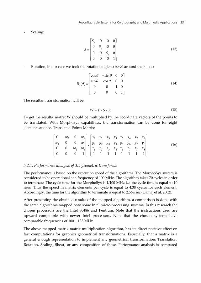
To get the results: matrix W should be multiplied by the coordinate vectors of the points to be translated. With MorphoSys capabilities, the transformation can be done for eight elements at once. Translated Points Matrix:
2 4 1 2 3 4 5 6 7 8
1 5 1 2 3 4 5 6 7 8
3 6 1 2 3 4 5 7 7 8
0 00 0
0 00 0 0 1 1 1 1 1 1 1 1 1
w w x x x x x x x xw w y y y y y y y y
w w z z z z z z z z
(16)
5.2.1. Performance analysis of 3D geometric transforms
The performance is based on the execution speed of the algorithms. The MorphoSys system is considered to be operational at a frequency of 100 MHz. The algorithm takes 70 cycles in order to terminate. The cycle time for the MorphoSys is 1/100 MHz i.e. the cycle time is equal to 10 nsec. Thus the speed in matrix elements per cycle is equal to 4.38 cycles for each element. Accordingly, the time for the algorithm to terminate is equal to 2.56 sec (Damaj et al, 2002).
After presenting the obtained results of the mapped algorithm, a comparison is done with the same algorithms mapped onto some Intel micro-processing systems. In this research the chosen processors are the Intel 80486 and Pentium. Note that the instructions used are upward compatible with newer Intel processors. Note that the chosen systems have comparable frequencies of 100 ~ 133 MHz.
The above mapped matrix-matrix multiplication algorithm, has its direct positive effect on fast computations for graphics geometrical transformations. Especially, that a matrix is a general enough representation to implement any geometrical transformation: Translation, Rotation, Scaling, Shear, or any composition of these. Performance analysis is compared
Data Acquisition Applications 24
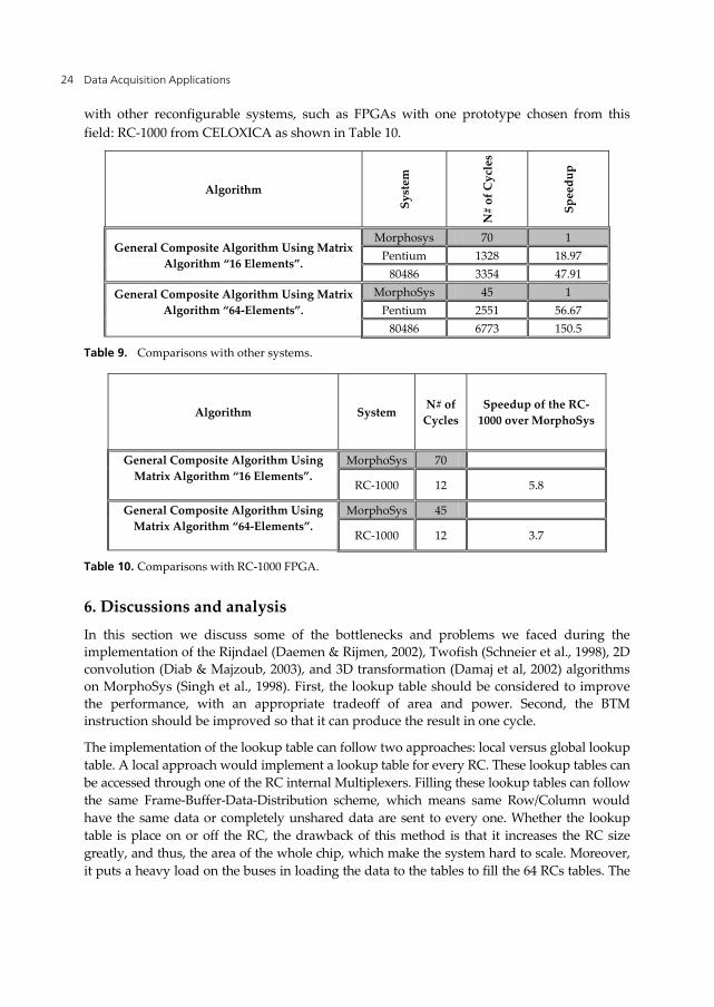
with other reconfigurable systems, such as FPGAs with one prototype chosen from this field: RC-1000 from CELOXICA as shown in Table 10.
Algorithm
Syst
em
N#
of C
ycle
s
Spee
dup
General Composite Algorithm Using Matrix Algorithm “16 Elements”.
Morphosys 70 1 Pentium 1328 18.97
80486 3354 47.91
General Composite Algorithm Using Matrix Algorithm “64-Elements”.
MorphoSys 45 1 Pentium 2551 56.67
80486 6773 150.5
Table 9. Comparisons with other systems.
Algorithm System N# of Cycles
Speedup of the RC-1000 over MorphoSys
General Composite Algorithm Using Matrix Algorithm “16 Elements”.
MorphoSys 70
RC-1000 12 5.8
General Composite Algorithm Using Matrix Algorithm “64-Elements”.
MorphoSys 45
RC-1000 12 3.7
Table 10. Comparisons with RC-1000 FPGA.
6. Discussions and analysis In this section we discuss some of the bottlenecks and problems we faced during the implementation of the Rijndael (Daemen & Rijmen, 2002), Twofish (Schneier et al., 1998), 2D convolution (Diab & Majzoub, 2003), and 3D transformation (Damaj et al, 2002) algorithms on MorphoSys (Singh et al., 1998). First, the lookup table should be considered to improve the performance, with an appropriate tradeoff of area and power. Second, the BTM instruction should be improved so that it can produce the result in one cycle.
The implementation of the lookup table can follow two approaches: local versus global lookup table. A local approach would implement a lookup table for every RC. These lookup tables can be accessed through one of the RC internal Multiplexers. Filling these lookup tables can follow the same Frame-Buffer-Data-Distribution scheme, which means same Row/Column would have the same data or completely unshared data are sent to every one. Whether the lookup table is place on or off the RC, the drawback of this method is that it increases the RC size greatly, and thus, the area of the whole chip, which make the system hard to scale. Moreover, it puts a heavy load on the buses in loading the data to the tables to fill the 64 RCs tables. The

Reconfigurable Systems for Cryptography and Multimedia Applications 25
advantage of this method is that it speeds the lookup access. So this method is the optimal in terms of speed but it is the worst in terms of area. In this option the size of the lookup table should be small and scaling up the RC Array size to more than 8×8 would be difficult.
A more global approach is to put one lookup table outside the RC Array that all the RCs can access. This option requires less area. It is feasible to increase the size of the lookup table here into the size of the frame buffer itself. The cost of loading data into the lookup table is then the same as the Frame Buffer. This global lookup table could be placed between the Frame Buffer and the RC Array. The data coming from the Frame Buffer to RC Array is multiplexed to the address bus of this lookup table and the needed data are passed to the RCs from this table. The distribution of the data on the RCs follows the same Frame-Buffer-Data-Distribution scheme. The disadvantage of this method is that all the RCs have the same lookup table. If another lookup table is needed then it should be reloaded. Another disadvantage is that it takes more time to access it by the RCs. The time is at least double the time accessing the Frame Buffer. This method will have lower performance.
A middle solution between the two methods is to have 8 lookup tables, where each one would cover one Row/Column. This way the access time is fast, because every lookup table is covering only one Row or Column. More over it will be reasonable in terms of area, because instead of 64 lookup tables only 8 are needed in this approach. Ideally, the speed up in case of lookup hardware implementation will be 96% in the best case and 82% in the worst per one round in the case of the Rijndeal algorithm. This improvement puts the MorphoSys into high competitive level with other platforms.
On the other hand, to improve the fine-grain capabilities in MorphoSys, the BTM instruction should be changed. For instance, it should be ANDing MUX_A and MUX_B and then XORing the bits of the output result instead of counting the 1’s. For instance, this implementation will save several cycles in the Mix and InvMix- Column. Other schemes could be implemented as well, so that the MorphoSys can handle fine-grain operations with a very good performance.
Instruction Mnemonic
Description
BWAX ANDing MUX_A and MUX_B, then XORing
all the output bits in the result
BWRA ORing MUX_A with MUX_B, then ANDing all
the bits in the output result
BWRP XORing MUX_A with MUX_C, then ORing the result with MUX B, then ANDing all the bits in
the output result
CNCT Concatenate the lower 8 bits from both
MUX_A and MUX_B. ORALL ORing MUX_A, MUX_B, and MUX_C
ANDALL ANDing MUX_A, MUX_B, and MUX_C XORALL XORing MUX_A, MUX_B, and MUX_C
Table 11. The proposed new RC-Instructions

Data Acquisition Applications 26
In order to improve the bit wise operations some new instructions should be implemented. Table 7 shows the proposed RC-instructions. Also, it is very useful to introduce another MUX_C to the RC. MUX_C can be identical to MUX_A. As the bus overhead to the RC itself already paid, it is useful to increase the use of these buses.
The first instruction, BWAX, is a bit wise XOR of input coming from MUX_A. The second instruction is calculating terms in Modulo-2 algebra. This instruction can help implementing new Modulo-2 compiler. The third instruction is to calculate Boolean terms. This instruction will help implementing a Boolean algebra compiler. These instructions are very useful in the Mix-Column and its inverse (InvMix-Column) in Rijndael as well as the MDS in Twofish.
The concatenate instruction is necessary to exploit the 16 bus width. Since the frame buffer bus is only 8 bits, the other 8 bits of the RC Array are useless most of the time, the RC bus width is 16 bits. So it is better either to reduce the RC bus width to 12, or may be 8, or to implement new instructions that can make use of the 16 bits. The other three instructions are to implement another level of parallelism on the RC level. These logical instructions are very easy to implement and can greatly help the performance. Since most of the cryptographic applications, as well as multimedia type of applications requires iterative and repetitive operations on different data.
7. Conclusion
In this chapter we implemented a number of multimedia applications, namely Rijndael, Twofish, image filtering and computer graphics algorithms. This implementation was carried out on a coarse grained reconfigurable architecture, MorphoSys, designed and implemented at UC Irvine. Furthermore, we presented the results of such implementations along with analyses and highlights of the current bottlenecks and problems. Solutions and possible workarounds are suggested to improve the performance results and further improve the MorphoSys hardware as a viable solution for multimedia applications.
Author details
Sohaib Majzoub American University in Dubai, Dubai, UAE
Hassan Diab American University of Beirut, Beirut, Lebanon
8. References Bagherzadeh, N., Kamalizad, A. H., & Koohi, A. (n.d.). Design and analysis of a programmable
single-chip architecture for DVB-T base-band receiver. 2003 Design, Automation and Test in Europe Conference and Exhibition (pp. 468-473). IEEE Comput. Soc. doi:10.1109/ DATE.2003.1253653

Reconfigurable Systems for Cryptography and Multimedia Applications 27
Bosi, B., Bois, G., & Savaria, Y. (1999). Reconfigurable Pipelined 2D Convolvers for Fast Digital Signal Processing. IEEE Trans. On Very Large Scale Integration (VLSI) Systems. Retrieved from http://citeseerx.ist.psu.edu/viewdoc/summary?doi=10.1.1.42.124
Christoforos E. Kozyrakis, D. A. P. (n.d.). A New Direction for Computer Architecture Research. Retrieved from http://citeseer.ist.psu.edu/viewdoc/summary?doi=10.1.1.146.743
Daemen, J., & Rijmen, V. (2002). The Design of RijndaeL: AES - The Advanced Encryption Standard (Information Security and Cryptography) (p. 255). Springer. Retrieved from http://www.amazon.com/Design-RijndaeL-Encryption-Information-Cryptography/dp/3540425802
Damaj, I., Majzoub, Sohaib, & Diab, Hassan. (2002). 2D and 3D Computer Graphics Algorithms under MORPHOSYS, 1076-1079. Retrieved from
http://portal.acm.org/citation.cfm?id=647929.740227 Diab, H., & Majzoub, S. (n.d.). Linear filtering using reconfigurable computing. ACS/IEEE
International Conference on Computer Systems and Applications, 2003. Book of Abstracts. (p. 15). IEEE. doi:10.1109/AICCSA.2003.1227452
Eguro, K., & Hauck, S. (n.d.). Issues and Approaches to Coarse-Grain Reconfigurable Architecture Development. Retrieved from
http://citeseerx.ist.psu.edu/viewdoc/summary?doi=10.1.1.15.3501 Ferrandi, F., Santambrogio, M. D., & Sciuto, D. (n.d.). A Design Methodology for Dynamic
Reconfiguration: The Caronte Architecture. 19th IEEE International Parallel and Distributed Processing Symposium (p. 163b-163b). IEEE. doi:10.1109/IPDPS.2005.17
Galanis, M. D., Theodoridis, G., Tragoudas, S., Soudris, D., & Goutis, C. E. (2004). A novel coarse-grain reconfigurable data-path for accelerating DSP kernels. Proceeding of the 2004 ACM/SIGDA 12th international symposium on Field programmable gate arrays - FPGA ’04 (p. 252). New York, New York, USA: ACM Press. doi:10.1145/968280.968337
Hartenstein, R. (2001, March 13). A Decade of Reconfigurable Computing: A Visionary Retrospective. Published by the IEEE Computer Society. Retrieved from: www.computer.org/portal/web/csdl/doi/10.1109/DATE.2001.915091
Hauck, S. (1998). The Future of Reconfigurable Systems. in 5th Canadian Conference on Field Programmable Devices. Retrieved from
http://citeseerx.ist.psu.edu/viewdoc/summary?doi=10.1.1.37.5820 Hauser, J. R., & Wawrzynek, J. (n.d.). Garp: a MIPS processor with a reconfigurable coprocessor.
Proceedings. The 5th Annual IEEE Symposium on Field-Programmable Custom Computing Machines Cat. No.97TB100186) (pp. 12-21). IEEE Comput. Soc. doi:10.1109/ FPGA.1997.624600
Itani, M., & Diab, Hassan. (2004). Reconfigurable Computing for RC6 Cryptography. Proceedings of the The IEEE/ACS International Conference on Pervasive Services (pp. 121–127). Washington: IEEE Computer Society. doi:10.1109/ICPS.2004.25
Lee, M.-hau, Singh, Hartej, Lu, G., Bagherzadeh, Nader, Kurdahi, Fadi J., Fadi, & Kurdahi, J. (2000). Design and Implementation of the MorphoSys Reconfigurable Computing Processor. Journal of VLSI and Signal Processing-Systems for Signal, Image and Video Technology. Retrieved from
http://citeseerx.ist.psu.edu/viewdoc/summary?doi=10.1.1.37.3761 Maestre, R., Kurdahi, F.J., Bagherzadeh, N., Singh, H., Hermida, R., & Fernandez, M. (n.d.).
Kernel scheduling in reconfigurable computing. Design, Automation and Test in Europe

Data Acquisition Applications 28
Conference and Exhibition, 1999. Proceedings (Cat. No. PR00078) (pp. 90-96). IEEE Comput. Soc. doi:10.1109/DATE.1999.761102
Majzoub, S., & Diab, H. (n.d.). Mapping and performance analysis of the Twofish algorithm on MorphoSys. ACS/IEEE International Conference on Computer Systems and Applications, 2003. Book of Abstracts. (p. 9). IEEE. doi:10.1109/AICCSA.2003.1227446
Majzoub, Sohaib, & Diab, Hassan. (2006). Instruction-Set Extension for Cryptographic Applications on Reconfigurable Platform. 2006 6th International Workshop on System on Chip for Real Time Applications (pp. 173-178). IEEE. doi:10.1109/IWSOC.2006.348231
Majzoub, Sohaib, & Diab, Hassan. (2010). MorphoSys reconfigurable hardware for cryptography: the twofish case. The Journal of Supercomputing, 1-20-20. Springer Netherlands. doi:10.1007/s11227-010-0413-3
Majzoub, Sohaib, Saleh, R., & Diab, Hassan. (2006). Reconfigurable Platform Evaluation Through Application Mapping And Performance Analysis. 2006 IEEE International Symposium on Signal Processing and Information Technology (pp. 496-501). IEEE. doi:10.1109/ISSPIT.2006.270852
Mei, B., Vernalde, S., Verkest, D., De Man, H., & Lauwereins, R. (2003). Field Programmable Logic and Application. (P. Cheung & G. A. Constantinides, Eds.)Lecture Notes in Computer Science (Vol. 2778, pp. 61-70). Berlin, Heidelberg: Springer Berlin Heidelberg. doi:10.1007/b12007
Mirsky, E., & DeHon, A. (1996). MATRIX: a reconfigurable computing architecture with configurable instruction distribution and deployable resources. Proceedings IEEE Symposium on FPGAs for Custom Computing Machines FPGA-96 (pp. 157-166). IEEE. doi:10.1109/FPGA.1996.564808
Miyamori, T., & Olukotun, K. (1998). REMARC: Reconfigurable Multimedia Array Coprocessor. IEICE Transactions on Information and Systems E82-D. Retrieved from http://citeseerx.ist.psu.edu/viewdoc/summary?doi=10.1.1.56.607
Möller, L., Soares, R., Carvalho, E., Grehs, I., Calazans, N., & Moraes, F. (2006). Infrastructure for dynamic reconfigurable systems. Proceedings of the 19th annual symposium on Integrated circuits and systems design - SBCCI ’06 (p. 44). New York, New York, USA: ACM Press. doi:10.1145/1150343.1150360
Schneier, B. (1996). Applied Cryptography: Protocols, Algorithms, and Source Code in C, Second Edition (p. 758). Wiley. Retrieved from http://www.amazon.com/Applied-Cryptography-Protocols-Algorithms-Source/dp/0471117099
Schneier, B., Kelsey, J., Whiting, D., Wagner, D., Hall, C., & Ferguson, N. (1998). Twofish: A 128-Bit Block Cipher. in First Advanced Encryption Standard (AES) Conference. Retrieved from http://citeseerx.ist.psu.edu/viewdoc/summary?doi=10.1.1.35.1273
Singh, H., Kurdahi, F.J., Bagherzadeh, N., & Filho, E. M. C. (n.d.). MorphoSys: a reconfigurable architecture for multimedia applications. Proceedings. XI Brazilian Symposium on Integrated Circuit Design (Cat. No.98EX216) (pp. 134-139). IEEE Comput. Soc. doi:10.1109/ SBCCI.1998.715427
Sklaos, N., & Koufopavlou, O. (2002). Architectures and VLSI implementations of the AES-Proposal Rijndael. IEEE Transactions on Computers, 51(12), 1454-1459. doi:10.1109/ TC.2002.1146712
Tessier, R., & Burleson, W. (2001). Reconfigurable Computing for Digital Signal Processing: A Survey. Journal of VLSI Signal Processing Systems, 28(1/2), 7-27. doi:10.1023/A:1008155020711