recommended standards and guidance for performance, application, design, and operation ... · ·...
TRANSCRIPT

Recommended Standards and Guidance forPerformance, Application, Design, and Operation &
Maintenance
Proprietary Distribution Technologies For Trenches, Seepage Beds, At-grades and Mounds
January 22, 2008 Technical Advisory Panel Meeting
Dick Bachelder, ADS/HancorBen Berteau, Ring Industrial GroupPeder Larson, Larkin Hoffman Daly & Lindgren Ltd.Carl Thompson, P.E., Infiltrator Systems, Inc.

Agenda
•
Brief Recap of December Meeting•
Review of Summarized Data on Warranty Systems
•
Applications of products in trenches (pressure and gravity), beds (pressure and gravity), at-grades (pressure) and mounds (pressure)
•
TAP Recommendations
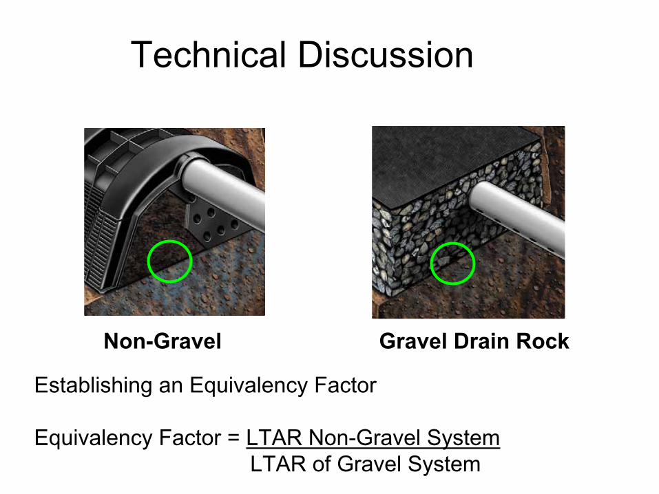
Gravel Drain Rock Non-Gravel
Technical Discussion
Establishing an Equivalency Factor
Equivalency Factor = LTAR Non-Gravel SystemLTAR of Gravel System

Technical DiscussionResearch Study Description of Study Equivalency Factor
(Septic Tank Effluent)
Sweeny, Robert. 2008. Field Inspection and Evaluation of the Hydraulic Performance of EZflow 1201P Gravel
Substitute Drainfield Systems in Clackamas, Marion, Multnomah and Deschutes Counties, Oregon. Presented
at 2008 OR DEQ Technical Advisory Committee meeting
436 field evaluations of 103 EZflow systems over a five year period for determining product failure rate
2.0
Christopherson et al. 2008. Field Comparison of Rock-Filled and Chambered Trench Systems in Journal of
Hydrologic Engineering, Vol. 13, No. 8,
Field evaluation of over 100 gravel and chamber systems 5 to 10
years old
No failures detected for either system type
Lowe et al. 2008. Controlled Field Experiment for Performance Evaluation of Septic Tank Effluent Treatment during Soil Evaluation, , Journal of
Environmental Engineering,
Two-year field study of 30 pilot-
scale test cells.
1.4 –
1.8
Walsh, R. 2006. Infiltrative Capacity of Receiving Media as Affected by Effluent Quality, Infiltrative Surface Architecture, and Hydraulic Loading Rate, Master
Thesis at Colorado School of Mines
One dimensional column study 3.2
Uebler et al. 2006. Performance of Chamber and EZ1203H Systems Compared to Conventional Gravel Septic Tank Systems in North Carolina, , Proceedings of NOWRA
Field evaluation of failure rates of approximately 300 of each
type system (gravel, chamber, EPS) 2-12 years old
1.4
Radcliffe et al. 2005. Gravel and Sidewall Flow Effects in On-Site System Trenches, , Soil Science Society of
America Journal
Two dimensional computer model (HYDRUS-2D)
1.5 –
1.93

Technical DiscussionResearch Study Description of Study Equivalency Factor
(Septic Tank Effluent)
Siegrist et al.2004. Wastewater Infiltration into Soil and the Effects of Infiltrative Surface Architecture, , Small
Flows Quarterly
Two one dimensional column studies and pilot-scale field
study
1.5 –
2.0
White and West. 2003. In-Ground Dispersal of Wastewater Effluent: The Science of Getting Water into the Ground.
Small Flows Quarterly, 2003
Literature Review and One dimensional column study
measuring the impact of gravel and fines (clean water)
2.5
King et al. 2002. Surface Failure Rates of Chamber and Traditional Aggregate-Laden Trenches in Oregon,
Small Flows Quarterly
Field evaluation of failure rates of 198 chamber systems and 191 gravel systems 2-5 years old
1.6
Burcham, T. 2001. A Review of Literature and Computations for Chamber-Style Onsite Wastewater Distribution Systems, , Report commissioned by the Mississippi
Department of Health
Literature review and computer model
1.43–
2.0
Joy, Douglas. 2001. Review of Chamber Systems and Their Sizing for Wastewater Treatment Systems, Ontario
Rural Wastewater Centre Report, University of Guelph
Literature Review 1.67
Van Cuyk et al, 2001. Hydraulic and Purification Behaviors and their Interactions During Wastewater Treatment in Soil Infiltration Systems”, Journal of Water Resources
Three-dimensional lysimeter study of treatment performance
1.67
Casper, Jay. 1997. Final Report: Infiltrator Side-by-Side Test Site, Killarney Elementary School, Winter Park,
Florida. Report to State of Florida, Department of HRS.
Pilot-scale side-by-side study of 15 trenches (gravel and chamber).
1.6 –
2.3

Technical DiscussionResearch Study Description of Study Equivalency Factor
(Septic Tank Effluent)
Keys, JR. 1996. Septic Tank Effluent Infiltration and Loading Rates for Gravel and Chamber Absorption
Systems. MS Thesis. University of Wisconsin-Madison
Triplicate comparison of 8 year old gravel and chamber systems i. No difference in performance
of silt loam systems even though chambers loaded 1.65 x higher. No comparison made
in sand.
1.65
Amerson, RS, Tyler, EJ, Converse, JC. 1991. Infiltration as Affected by Compaction, Fines and Contact Area of
Gravel,
in
On-Site Wastewater Treatment: Proceedings of 6th
National Symposium On Individual and Small Community Sewage Systems, American Society of
Agricultural Engineers, St. Joseph, MI, December 1991
Evaluation of 30 soil cells to assess impact of gravel compaction, contact area and fines. Ratios are the clean water infiltration
rate ratios of an open soil surface (control) compared to one with gravel compaction,
embedment, and fines.
2.1 –
2.6
Other References2006. Uniform Plumbing Code. International Standard 1.43
Siegrist, Robert. 2006. Evolving a Rational Design Approach for Sizing Soil Treatment Units, Small
Flows Quarterly. Summer 2006
Proposed design methodology that takes into account BOD
loading, soil type and infiltrative surface
architecture.
1.33 –
2.0
2001. U.S. EPA Decentralized Systems Technology Fact Sheet –
Septic Tank Leaching Chambers.Literature Review and
Recommended Usage1.4

Product Rating (sf/lf) = Trench Width x Equivalency Factor
Equivalency Factor = LTAR Non-Gravel SystemLTAR of Gravel System
Examples:
•
3’ wide trench x 2.00
equivalency factor = 6 sf/lf (50% Gross area reduction)
•
3’ wide trench x 1.67
equivalency factor = 5 sf/lf (40% Gross area reduction)
•
3’ wide trench x 1.33
equivalency factor = 4 sf/lf (25% gross area reduction)
How Our Products Are Used
Research indicates multiplier in the 1.4 –
3.2 range

Warranty ExperienceInfiltrator Systems
–
Approximately 17,000 systems installed over the last 13 years (1996 –
2008)
–
23 Malfunctioning systems reported and investigated (0.1%) –
Includes all systems 1:1 and warranty
Failure Observed FrequencyInstaller error (installation did not match design) –
includes chambers crushed during installation 8
Gopher damage to chambers or supply Lines 5Homeowner Abuse/Excessive Flows 4
Soil Intrusion 3High Groundwater table 1
System design doesn't match soil type 1Unknown 1
23

Warranty ExperienceAdvanced Drainage Systems (ADS) Chambers
–
Approximately 4,500 systems installed –
4 Malfunctioning systems reported (0.1%)
Ring Industrial Group –
EZFlow –
Approximately 800 systems installed
–
No malfunctioning systems reported
Combined: 1 Malfunctioning system for every 825 systems installed

Draft DocumentCovers Chambers and Expanded Polystyrene Aggregate Bundles For
Trenches, Seepage Beds, At-grades and Mounds

Conclusion: Draft DocumentDesign and Installation Considerations using Proprietary
Distribution Technologies (trenches or beds)
•
The infiltrative surface area of proprietary distribution technologies shall be determined by dividing the design flow (Gallons Per Day) by the appropriate soil loading rate (Gallons per Day per Square Foot) and multiplying that area by an efficiency factor of 0.75.
0.75 multiplier represents a 1.33 equivalency factor
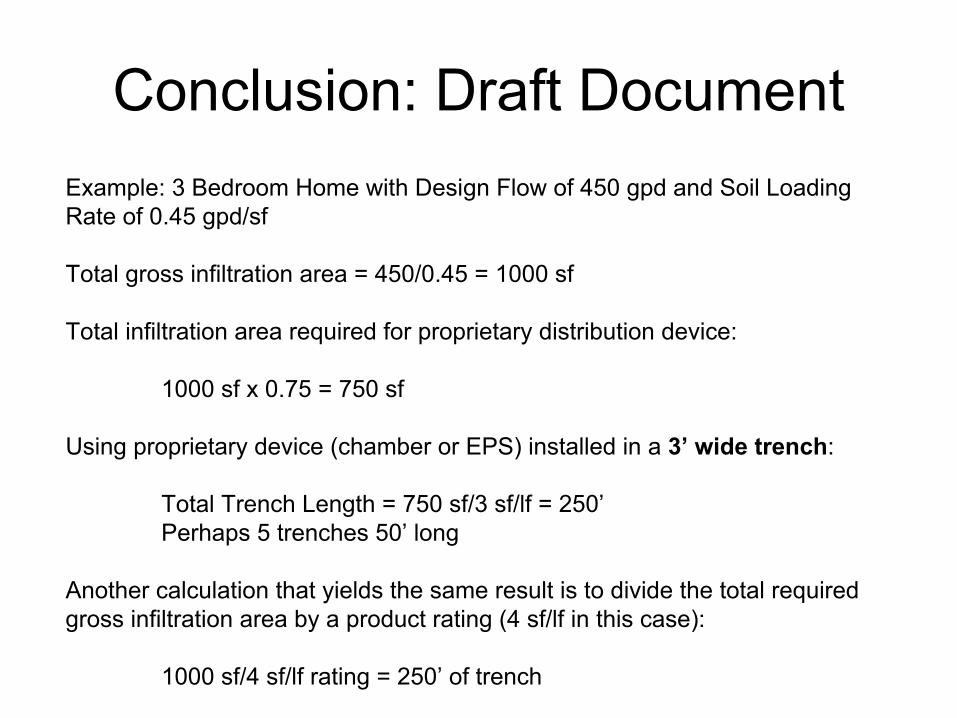
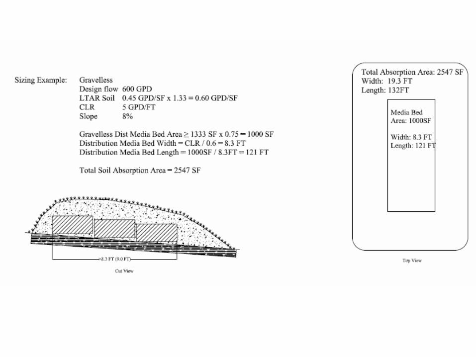
Conclusion: Draft DocumentExample: 3 Bedroom Home with Design Flow of 450 gpd and Soil Loading Rate of 0.45 gpd/sf
Total gross infiltration area = 450/0.45 = 1000 sf
Total infiltration area required for proprietary distribution device:
1000 sf x 0.75 = 750 sf
Using proprietary device (chamber or EPS) installed in a 3’ wide trench:
Total Trench Length = 750 sf/3 sf/lf = 250’Perhaps 5 trenches 50’ long
Another calculation that yields the same result is to divide the
total required gross infiltration area by a product rating (4 sf/lf in this case):
1000 sf/4 sf/lf rating = 250’ of trench

Conclusion: Draft DocumentMound design standards for proprietary distribution technologies
•
The original soil mound absorption area shall not be reduced. The original soil mound absorption area is determined by multiplying the original soil mound absorption length by the original soil mound absorption width. The original soil mound absorption width is calculated by multiplying the predetermined mound distribution media bed width by the mound absorption ratio found
in Table IX or IXa in part 7080.2150, subpart 2, item E.
•
Mound distribution media bed area for proprietary systems may vary by 10% in width and length from the required area for bed using gravel media.
•
All other mound system requirements found in 7080.2200 shall be adhered to.

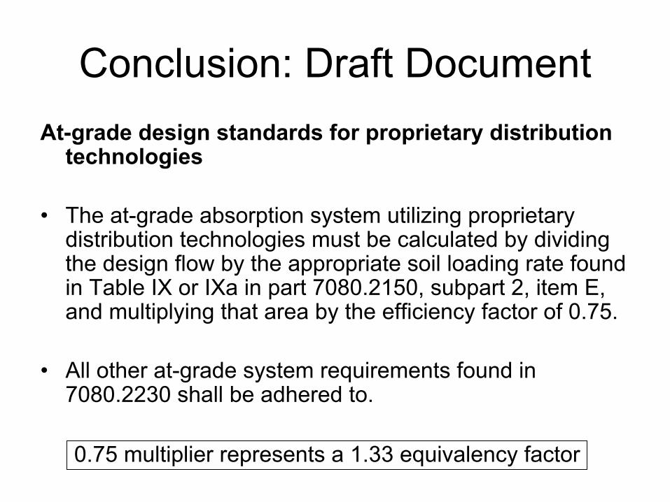
Conclusion: Draft DocumentAt-grade design standards for proprietary distribution
technologies
•
The at-grade absorption system utilizing proprietary distribution technologies must be calculated by dividing the design flow by the appropriate soil loading rate found in Table IX or IXa in part 7080.2150, subpart 2, item E, and multiplying that area by the efficiency factor of 0.75.
•
All other at-grade system requirements found in 7080.2230 shall be adhered to.
0.75 multiplier represents a 1.33 equivalency factor

Going Forward
•
Develop guidance document to cover these proprietary distribution devices–
once adopted we see no need for the for the “warranty” system sizing –
1.67 multiplier (40%
reduction)•
With a general guidance document in place, individual submittals are relatively simple–
Dimensions of products
–
Installation instructions

SummaryDemonstrated Equivalency Factor Range:
1.4 –
3.2
Manufacturer’s Recommendation for MN1.33 (25% gross area reduction)
Dick Bachelder, ADS/HancorBen Berteau, Ring Industrial GroupPeder Larson, Larkin Hoffman Daly & Lindgren Ltd.Carl Thompson, P.E., Infiltrator Systems, Inc.
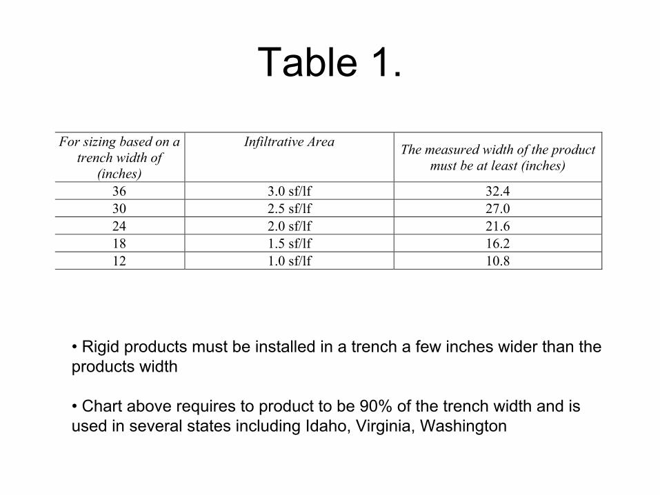
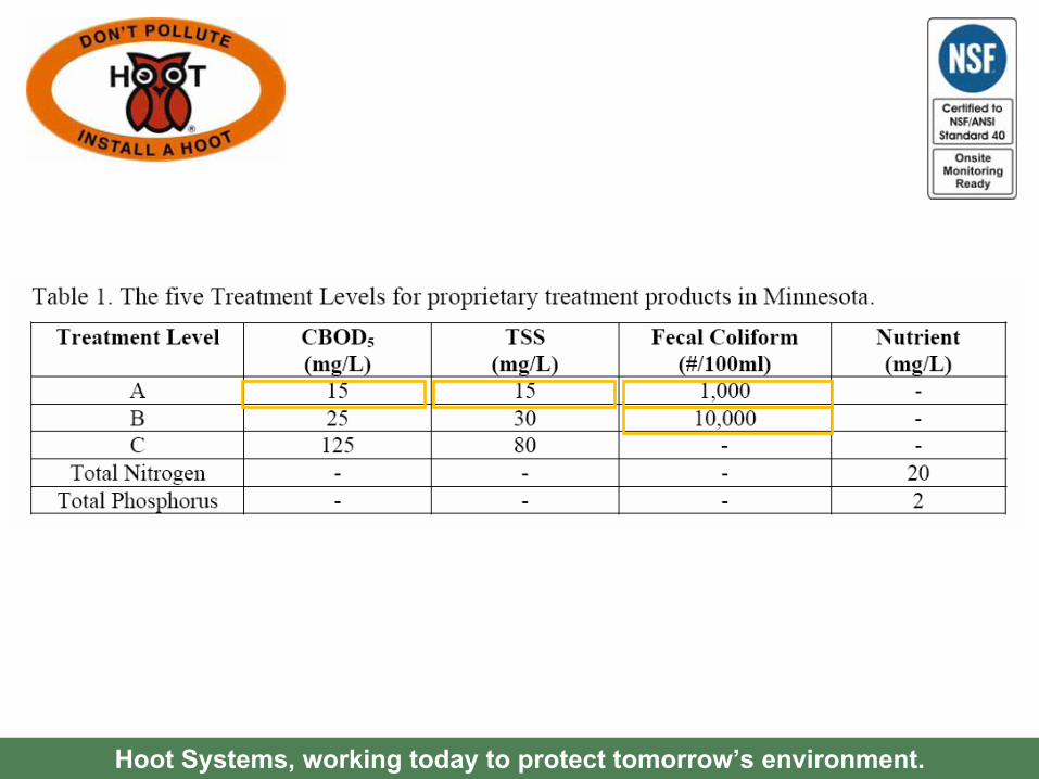
Table 1.
For sizing based on a trench width of
(inches)
Infiltrative Area The measured width of the product must be at least (inches)
36 3.0 sf/lf 32.4 30 2.5 sf/lf 27.0 24 2.0 sf/lf 21.6 18 1.5 sf/lf 16.2 12 1.0 sf/lf 10.8
•
Rigid products must be installed in a trench a few inches wider
than the products width
•
Chart above requires to product to be 90% of the trench width and is used in several states including Idaho, Virginia, Washington

Trench Width Measurement
Keys, 1996
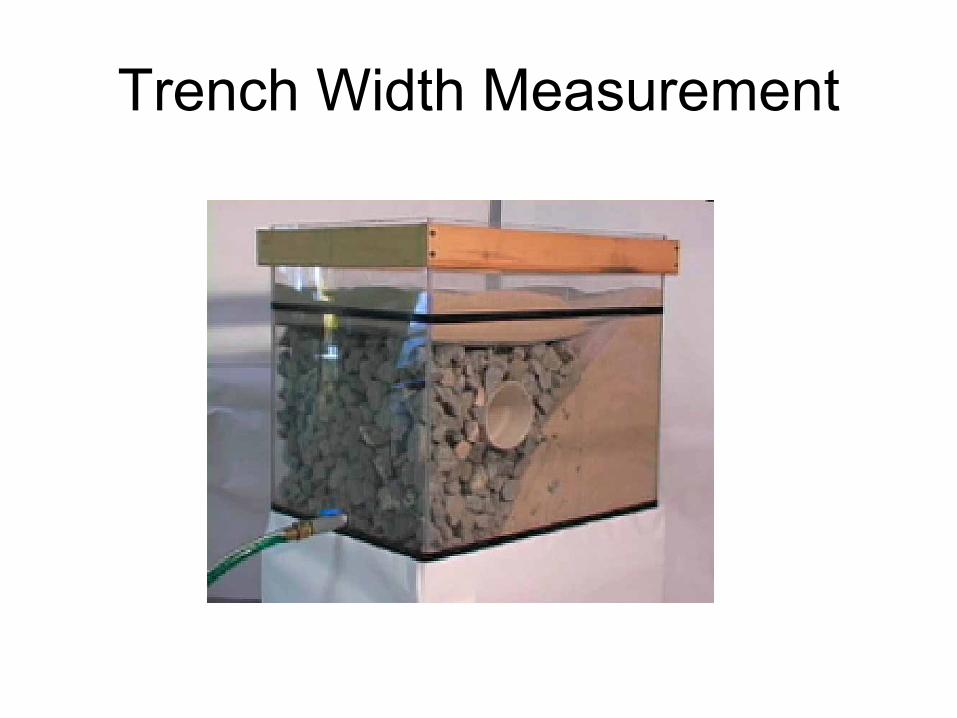
Trench Width Measurement

Multi-Flo and Nayadic Wastewater Treatment Systems
Minnesota TAC PresentationJanuary 22, 2009

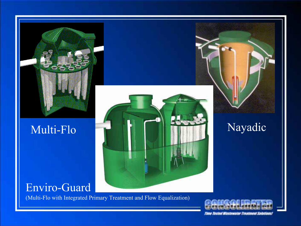
Multi-Flo Nayadic
Enviro-Guard(Multi-Flo with Integrated Primary Treatment and Flow Equalization)

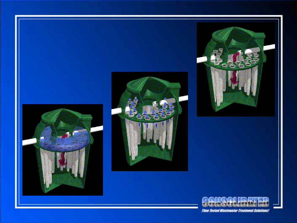
Multi-Flo

•
Developed in the 1970’s•
Among First Products Tested at NSF–
C-9
–
Standard 40
•
Continuous Production Over 35 Years•
50,000+ Units in Operation
•
Conforms to Standard Wastewater Processes–
Combined Process Operation
•
Capacities Range from 500 GPD to 1,500 GPD
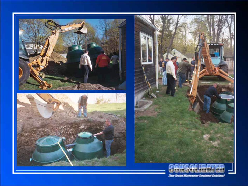
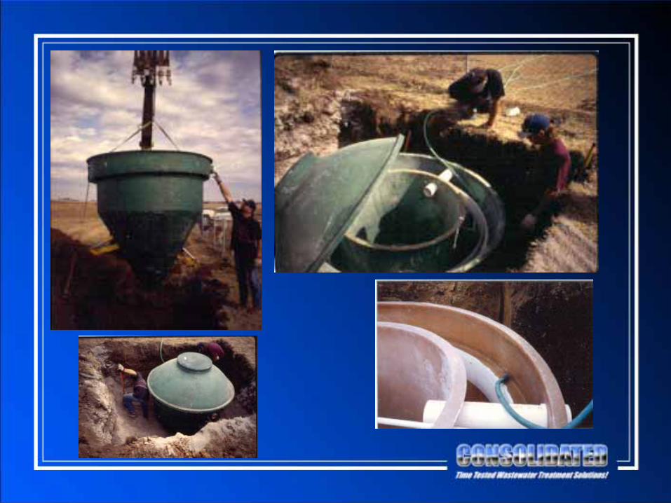
Multi-Flo
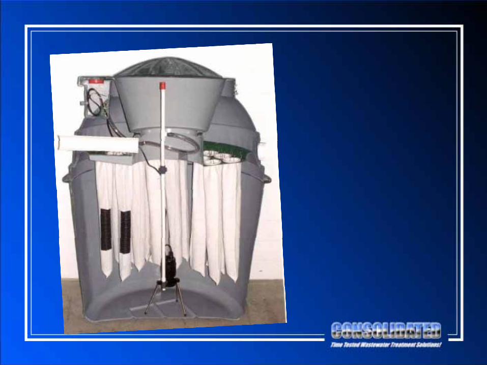
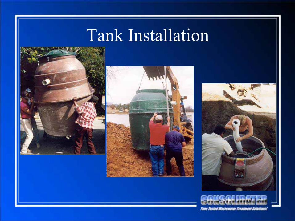
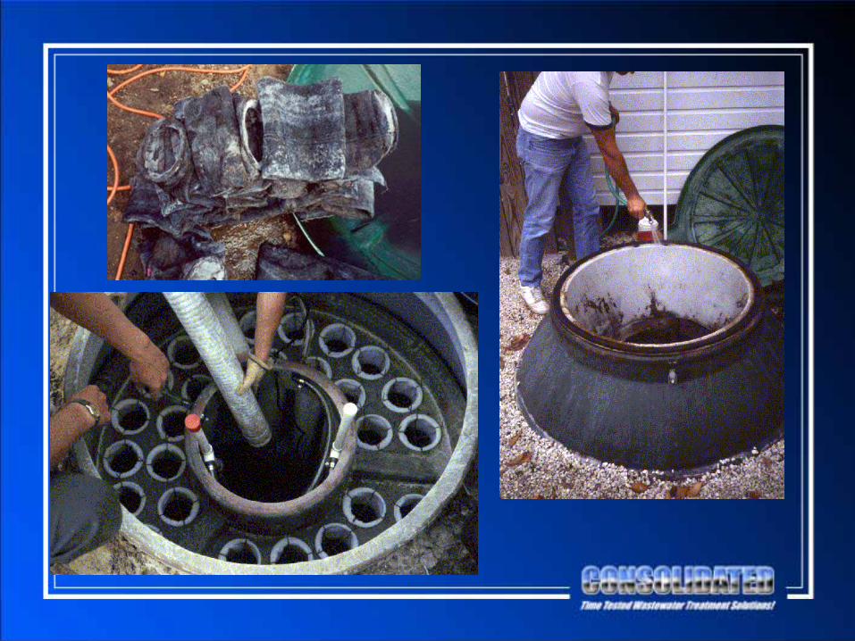
Tank Installation
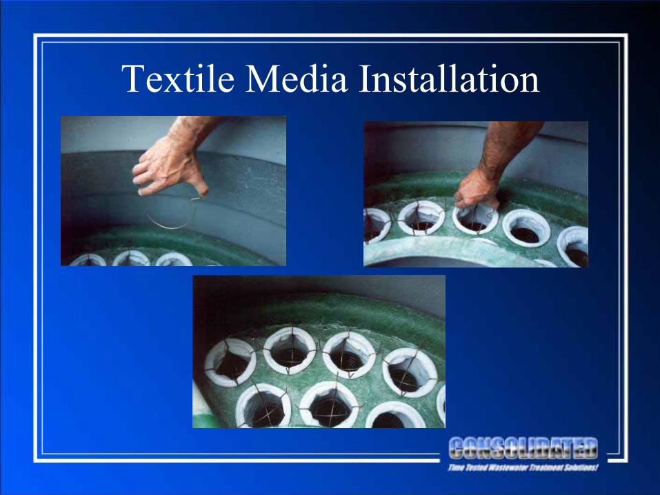
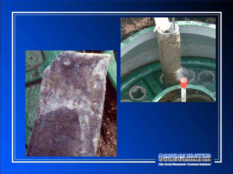
Textile Media Installation
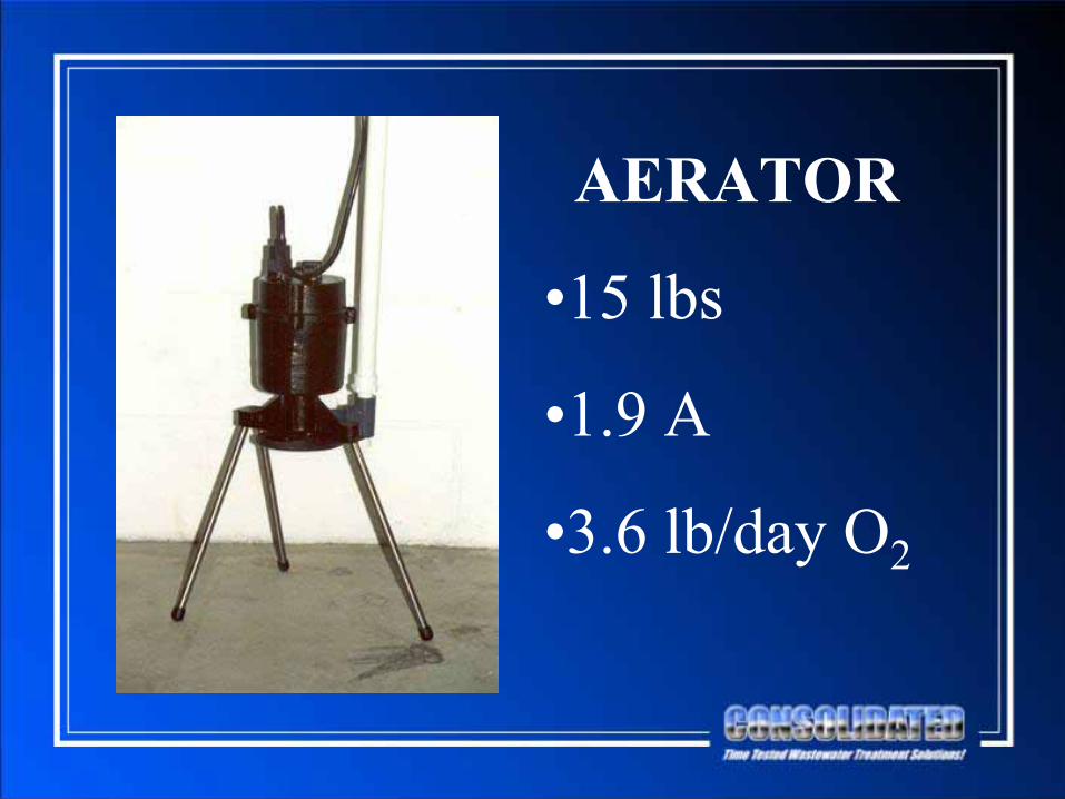
AERATOR
•15 lbs
•1.9 A
•3.6 lb/day O2
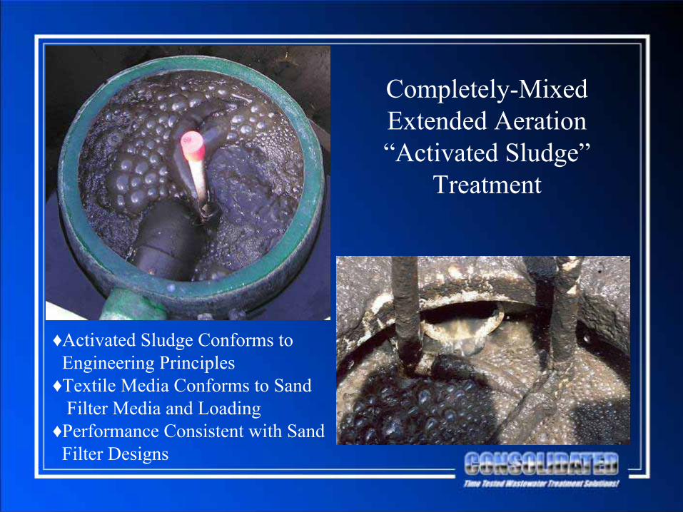
Completely-MixedExtended Aeration“Activated Sludge”
Treatment
♦Activated Sludge Conforms to
Engineering Principles♦Textile Media Conforms to Sand
Filter Media and Loading♦Performance Consistent with Sand
Filter Designs
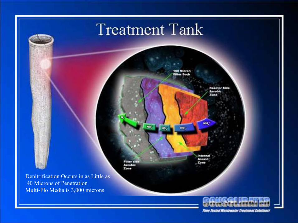
Denitrification Occurs in as Little as
40 Microns of Penetration
Multi-Flo Media is 3,000 microns

CBOD = 5 mg/L
TSS = 5 mg/L
TN = 14 mg/L
Coliform = 540 cfu/100 mL

Operation and Maintenance
•
Clean Weir Plate•
Conduct Settleability Test
•
Confirm Proper Operation of Components•
Perform “Sight and Smell” Observations
•
Pump Solids as Required (3-to-5 Years)

Independent Studies Document and Confirm Performance from 1970’s to
Present•
NSF Certification Tests, 1970-2008
•
University of Wisconsin SSWMP Studies, 1990’s
•
University of Dayton Studies, 2001-2003
•
NovaTec Studies, 2006-2008
•
Other Monitoring, 1980’s-Present
Enviro-Guard
•
Special Case of Multi-Flo–
Integrated Primary Treatment
–
Flow Equalization–
Separate Certification for ANSI/NSF Standard 40
•
Specific Uses–
“Tight” Locations
–
Unique Regulatory Requirements

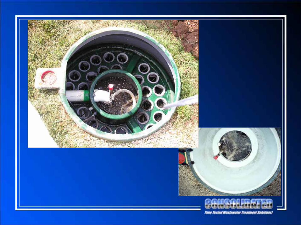
Enviro-Guard
Enviro-Guard
•
525-Gal Primary Treatment Tank•
600-Gal Dose Tank with Pump
•
Controlled Dosing–
30-Minute Intervals
48 Doses/Day
–
15.625-Gal Doses
5-GPM Dose Flow
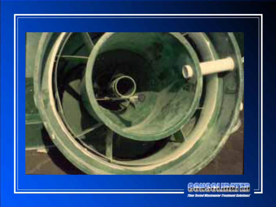
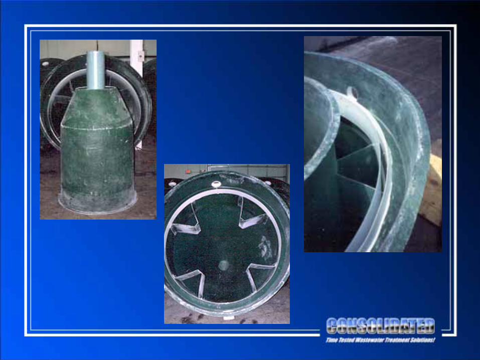
Nayadic Systems

Nayadic Systems•
Developed in 1960’s by Nayadic Sciences
•
Purchased by CTS in 1992•
Origins in the Imhoff Cone from late 1800’s
•
Design Conforms to Classic Wastewater Theory–
Aeration
–
Clarification
•
In Continuous Production Over 40 Years•
100,000+ Installations Worldwide
•
Certified Under ANSI/NSF Standard 40
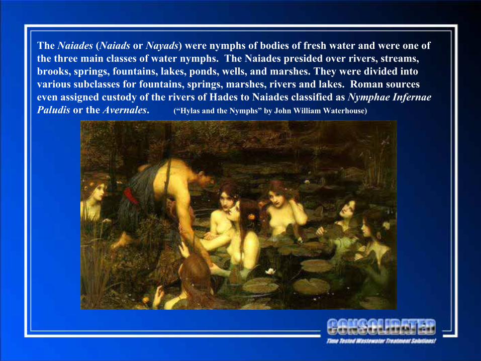
The Naiades
(Naiads
or Nayads) were nymphs of bodies of fresh water and were one of the three main classes of water nymphs. The Naiades
presided over rivers, streams, brooks, springs, fountains, lakes, ponds, wells, and marshes. They were divided into various subclasses for fountains, springs, marshes, rivers and lakes. Roman sources even assigned custody of the rivers of Hades to Naiades
classified as Nymphae
Infernae
Paludis
or the Avernales. (“Hylas
and the Nymphs” by John William Waterhouse)

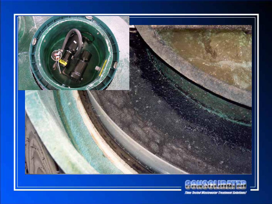
Nayadic SystemsAeration/Mixing
Clarification
360o Weir
Venturi Action
Aeration
Solids ConcentrationAnd Recycling
Nayadic Performance
•
As Low as 6 mg/L CBOD5
and TSS•
Typical: 10 mg/L CBOD5
and 15 mg/L TSS

Operation and Maintenance
•
Clean Behind Scum Baffle•
Clean/Replace Air Filter
•
Conduct Settleability Test•
Confirm Proper Operation of Components
•
Perform “Sight and Smell” Observations•
Pump Solids as Required (2-to-4 Years)


Disinfection
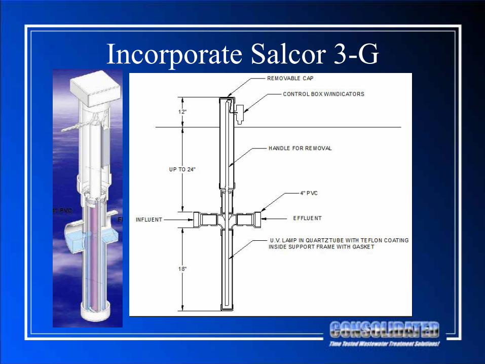
Incorporate Salcor 3-G

Salcor 3-G
•
Typical Performance is <2 cfu/100 mL•
Much Performance Data but None Conforming to MPCA Rules
•
Data Forthcoming

Flow Distribution

Flow Distribution•
Generally the Purview of the Designer, Dealer, or Installer—Based on Local Requirements and Conditions
•
General Guidelines:–
Divide Flow Equally Among Units
–
Adjustable Device•
CTS Has Not Mandated Specific Flow Splitting Devices or Designs as Flow Splitting Has Not Been an Issue
•
CTS will Cooperate with MPCA as Necessary to Provide Guidance to Dealers/Distributors/Installers
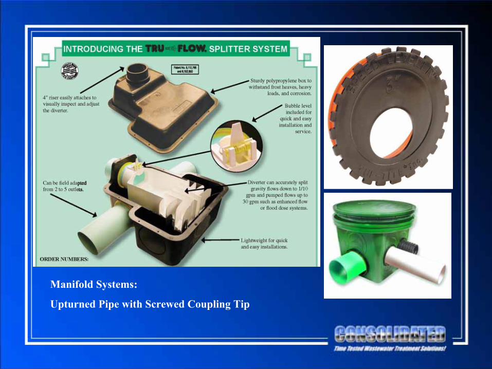
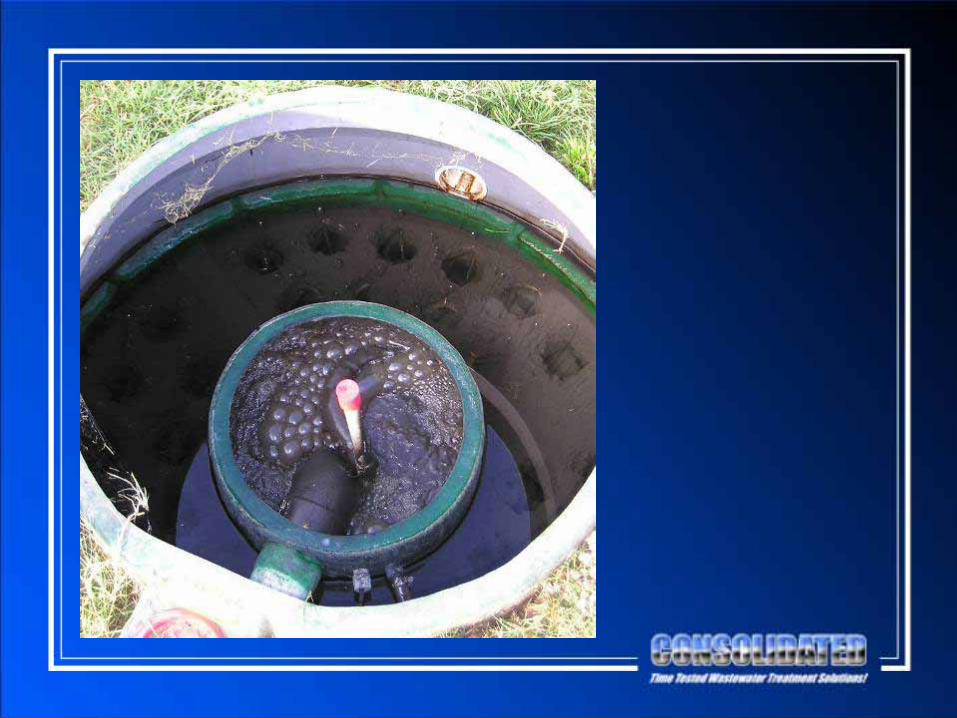
Manifold Systems:
Upturned Pipe with Screwed Coupling Tip

Multi-Flo and Nayadic
•
Continuous, Successful Operation for Over 35 Years
•
Continuous Certification Through NSF•
Satisfied Dealers and Homeowners
•
Questions??

Hoot Systems, working today to protect tomorrow’s environment.
Minnesota Pollution Control AgencySubsurface Sewage Treatment Systems (SSTS)
Technical Advisory Panel (TAP) for Product Registration
January 22, 2009
Presentation to the:

Hoot Systems, working today to protect tomorrow’s environment.
H-Series Hoot(Category B)

Hoot Systems, working today to protect tomorrow’s environment.
H-Series Hoot + Salcor UV
(Category A)

Ammonia Data
Hoot Systems, working today to protect tomorrow’s environment.
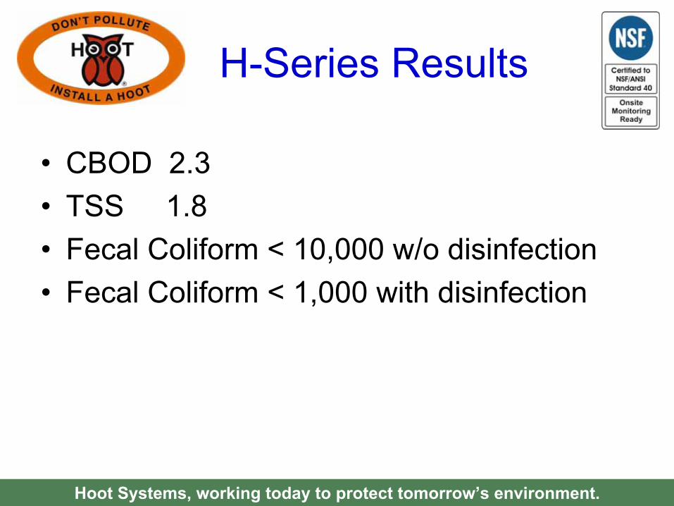
•
CBOD 2.3•
TSS 1.8
•
Fecal Coliform < 10,000 w/o disinfection•
Fecal Coliform < 1,000 with disinfection
Hoot Systems, working today to protect tomorrow’s environment.
H-Series Results
CBOD5
& TSS
Hoot Systems, working today to protect tomorrow’s environment.


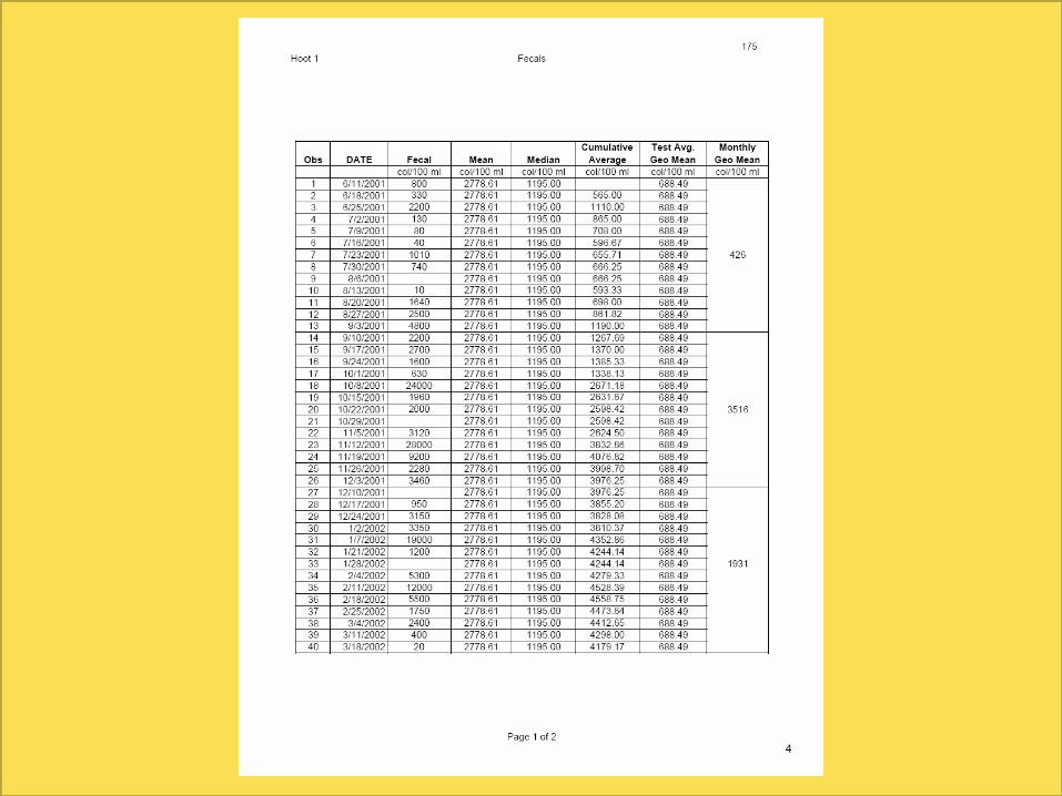
Fecal Results
Hoot Systems, working today to protect tomorrow’s environment.
Fecal Data<10,000
Hoot Systems, working today to protect tomorrow’s environment.


Hoot Systems, working today to protect tomorrow’s environment.
H-Series Hoot(Category B)


173

Fecal <1,000
Hoot Systems, working today to protect tomorrow’s environment.


Hoot Systems, working today to protect tomorrow’s environment.
H-Series Hoot + Salcor UV
(Category A)


Any Questions?
Hoot Systems, working today to protect tomorrow’s environment.


Hoot Systems, working today to protect tomorrow’s environment.
H-Series Hoot(Baseline)

Hoot Systems, working today to protect tomorrow’s environment.
Hoot BNR(Test Under Way)
Hoot Systems, working today to protect tomorrow’s environment.
Hoot ANR(Carbon Loaded)
Standard 40 & 245 Certified